23231085 - bureau of indian standards5349-5351)_24062016.pdf · iso 6508-3:2015 metallic doc:mtd...
TRANSCRIPT
टलीफकस : 23231085 Please Contact at Telefax 23231085 E-mail: [email protected]. in
यापकपरिचालनममस दा DRAFT IN WIDE CIRCULATION
रलखरषणसचना/DOCUMENT DESPATCH ADVICE
एमटीडी 3/टी-124, 125, 126, MTD 3/T-124, 125, 126, date 24 06 2016
धातओ क यारिकीय पिीषण सबधत विषय सलमनत एमटीडी03
MECHANICAL TESTING OF METALS SECTIONAL COMMITTEE, MTD 03
क)धातकममइजीननयरिगविभागपरिषद(एमटीडीसी), कचचिखनिालसदय
1) Interested Members of Metallurgical Engineering Division Council, MTDC
1)धातओ क यारिकीय पिीषण सबधत विषय सलमनत एमटीडी03कसदय 2)All Members of Mechanical Testing of Metals Sectional Committee, MTD 03
ग)अयसभीचचिखनिालननकाय
3) All Others Interested
मह दय/मह दया, Dear Sir/ Madam,
नननललखखतरलखसलनह:
Please find enclosed the following draft standards:
रलख स या /Document No. विषय/ Title
1. रलख: एमटीडी 03 (5349)धाविकसामरी-ि किलकठ ितापिीषणभाग 1 परीषण पधति ( कल A, B, C,
D, E, F, G, H, K, N, T ) (आइएस1586(Pt 1)का पाचि पनिीषण )(आइएसओ 6508-
1:2015 पिआधरित) MTD 3(5349)W Metallic materials – Rockwell hardness test Part 1 Test Method (Scales A, B, C,
D, E, F, G, H, K, N, T) (fifth revision of IS 1586(Pt 1) (Based on ISO 6508-1:2015)
2. रलख: एमटीडी 03 (5350)धाविकसामरी-ि किलकठ ितापिीषणभाग 2 परीषण मशीन का स यापन एि अशशोधन ( कल A, B, C, D, E, F, G, H, K, N, T ) (आइएस1586(Pt 2का पाचि पनिीषण) (आइएसओ 6508-2:2015 पिआधरित) MTD 3 (5350)W Metallic materials – Rockwell hardness test Part 2 Verification and Calibration
of Testing Machines (Scales A, B, C, D, E, F, G, H, K, N, T) (fifth revision of IS
1586(Pt 2) (Based on ISO 6508-2:2015)
3. रलख: एमटीडी 03 (5351)धाविकसामरी-ि किलकठ ितापिीषणभाग 3 सदभभ लाक का अशशोधन
( कल A, B, C, D, E, F, G, H, K, N, T ) (आइएस1586(Pt 3)का पाचि पनिीषण )
(आइएसओ 6508-3:2015पिआधरित) MTD 3(5351)W Metallic materials – Rockwell hardness test Part 3 Calibration of Reference
Blocks (Scales A, B, C, D, E, F, G, H, K, N, T) (fifth revision of IS 1586(Pt 3)
(Based on ISO 6508-3)
कयाउपि तरलख काअिल कनकि अपनीसमनतयायहबतातहएभज, ककयददअतत:यहरलखिाटरीयमानककपमिीकतह जाए, त इसपिअमलकिनमआपकयिसायअथिाकाि बािमयाकठनाईया आसकतीह।
Kindly examine this draft amendments and forward your views stating any difficulty which you are likely
to experience in your business or profession, if this is finally adopted as National Standard.
समनतकीअतमनतचथ/ Last date for comments: 24 08 2016
समनतयददक ईह त पीछददएगएरापमललखकि, ऊपिललखखतपतपिअध हताषिीक भज। Comments, if any, may please be made in the format given overleaf and mailed to the undersigned at the
above address.
धयिाद, Thanking you, भिदीय, yours faithfully,
(ज.क. बाख) (J.K. Bakhroo)
िञाननक‘एफ’ रमख(एमटीडी.)Scientist ‘F’ & Head (MTD)
सलन:ऊपिललखखत /Encl: As above
For Comments Only Doc:MTD 3(5349)W ISO 6508-1:2015
BUREAU OF INDIAN STANDARDS Draft Indian Standard
METALLIC MATEIALS – ROCKWELL HARDNESS TEST PART 1 TEST METHOD (SCALES A, B, C, D, E, F, G, H, K, N, T)
(Fifth Revision of IS 1586(Pt 1) ICS 77.040.10
Not to be reproduced without the permission of Last date for receipt of BIS or used as STANDARD comments is 24 08 2016
NATIONAL FOREWORD
This draft standard which is identical to ISO 6508-1:2015 Metallic materials –Rockwell hardness test Part 1 Test Method (Scales A, B, C, D, E, F, G, H, K, N, T) issued by the International Organization for Standardization (ISO), and subject to its finalization, is to be adopted by the Bureau of Indian Standards on the recommendation of the Mechanical Testing of Metals Sectional Committee, MTD 3 and approval of the Metallurgical Engineering Division Council.
This standard was originally published in 1960 and subsequently revised in 1968, 1988, 2000 and 2012. This revision is being undertaken as the corresponding ISO 6508-1:2005 has been revised as ISO 6508-1:2015. Similarly, this standard is also published in three parts: The other parts in this series are: Part 2 Verification and calibration of testing machines (scales A, B, C, D, E, F, G, H, K, N, T)
Part 3 Calibration of reference blocks (scales A, B, C, D, E, F, G, H, K, N, T) In this adopted draft standard, certain terminology and conventions are, however, not identical with those used in Indian Standard. Attention is especially drawn to the following:
a) Wherever the words `International Standard’ appear, referring to this standard, it should be as read as `Indian Standard’
b) Comma (,) has been used as a decimal marker while in Indian Standards the current practice is to use a point (.) as the decimal marker.
In this adopted draft standard, reference appears to certain International Standards for which Indian Standards also exists. The corresponding Indian Standards which are to be substituted in their place are listed below along with their degree equivalence for the editions indicated:
International Standard Corresponding Indian Standard Degree of Equivalence
ISO 6508-2:2015 Metallic Doc:MTD 3(5350) Metallic materials - Identical with materials – Rockwell Rockwell hardness test Part 2 Verification ISO 6508-2:2015 hardness test − Part 2: and calibration of testing machines Verification and calibration (Scales A, B, C, D, E, F, G, H, K, N, T of testing machines (First revision of IS 1586(Pt 2)
ISO 6508-3:2015 Metallic Doc:MTD 3(5351) Metallic materials - Identical with Materials − Rockwell hardness Rockwell hardness test Part 3 Calibration ISO 6508-3:2015 test − Part 3 Calibration of of reference blocks (Scales A, B, C, D, E, reference blocks F, G, H, K, N, T) (Fifth revision of IS 1586(Pt 3) In reporting the results of a test or analysis made in accordance with this standard, if the final value, observed or calculated, is to be rounded off, it shall be done in accordance with IS 2:1960 `Rules for rounding off numerical values (revised)’.
For Comments Only Doc:MTD 3(5350)W ISO 6508-2:2015
BUREAU OF INDIAN STANDARDS Draft Indian Standard
METALLIC MATEIALS – ROCKWELL HARDNESS TEST PART 3 VERIFICATION AND CALIBARATION OF TESTING MACHINES
(SCALES A, B, C, D, E, F, G, H, K, N, T) (Fifth Revision of IS 1586(Pt 2)
ICS 77.040.10
Not to be reproduced without the permission of Last date for receipt of BIS or used as STANDARD comments is 2408 2016
NATIONAL FOREWORD This draft standard which is identical to ISO 6508-2:2015 Metallic materials –Rockwell hardness test Part 3 Calibration of reference blocks (Scales A, B, C, D, E, F, G, H, K, N, T) issued by the International Organization for Standardization (ISO), and subject to its finalization, is to be adopted by the Bureau of Indian Standards on the recommendation of the Mechanical Testing of Metals Sectional Committee, MTD 3 and approval of the Metallurgical Engineering Division Council.
This standard was originally published in 1960 and subsequently revised in 1968, 1988, 2000 and 2012. This revision is being undertaken as the corresponding ISO 6508-2:2005 has been revised as ISO 6508-2:2015.
Similarly, this standard is also published in three parts: The other parts in this series are: Part 1 Test Method (Scales A, B, C, D, E, F, G, H, K, N, T)
Part 3 Calibration of reference blocks (Scales A, B, C, D, E, F, G, H, K, N, T) In this adopted draft standard, certain terminology and conventions are, however, not identical with those used in Indian Standard. Attention is especially drawn to the following:
a) Wherever the words `International Standard’ appear, referring to this standard, it should be as read as `Indian Standard’
b) Comma (,) has been used as a decimal marker while in Indian Standards the current practice is to use a point (.) as the decimal marker.
In this adopted draft standard, reference appears to certain International Standards for which Indian Standards also exists. The corresponding Indian Standards which are to be substituted in their place are listed below along with their degree equivalence for the editions indicated:
International Standard Corresponding Indian Standard Degree of Equivalence
ISO 376:2011 Metallic materials – IS 4169:2014/ISO 376:2011 Metallic Identical with Calibration of force proving materials – Calibration of force proving ISO 376:2011 instruments used for the instruments used for the verification verification of uniaxial testing of uniaxial testing machines (second machinesrevision) ISO 6507-1:2005 Metallic IS 1501:2013/ISO 6507-1:2005 Identical with Materials – Vickers hardness Metallic materials – Vickers hardness ISO 6507-1:2005 Test – Part 1 Test method test – Part 1 Test method ISO 6508-1:2015 Metallic Doc:MTD 3(5349)Metallic materials - Identical with materials – Rockwell hardness Rockwell hardness test – Part 1 Test ISO 6508-1:2015 Test – Part 1 Test Method Method (Scales A, B, C, D, E, F, G, H, K, N, T) (fourth revision of IS 1586(Pt 1)

ISO 6508-3:2015 Metallic Doc:MTD 3(5351)Metallic materials - Identical with Materials − Rockwell hardness Rockwell hardness test – Part 2 ISO 6508-3:2015 test − Part 3 Calibration of Verification and calibration of testing reference blocks machines (Scales A, B, C, D, E, F, G, H, K, N, T) (fourth revision of IS 1586 (Pt 2) In reporting the results of a test or analysis made in accordance with this standard, if the final value, observed or calculated, is to be rounded off, it shall be done in accordance with IS 2:1960 `Rules for rounding off numerical values (revised)’.
For Comments Only Doc:MTD 3(5351)W ISO 6508-3:2015
BUREAU OF INDIAN STANDARDS Draft Indian Standard
METALLIC MATEIALS – ROCKWELL HARDNESS TEST PART 3 CALIBARATION OF REFERENCE BLOCKS (SCALES A, B, C, D, E, F, G, H, K, N, T)
(Fifth Revision of IS 1586(Pt 3) ICS 77.040.10
Not to be reproduced without the permission of Last date for receipt of BIS or used as STANDARD comments is 24 08 2016
NATIONAL FOREWORD
This draft standard which is identical to ISO 6508-3:2015 Metallic materials –Rockwell hardness test Part 3 Calibration of reference blocks (Scales A, B, C, D, E, F, G, H, K, N, T) issued by the International Organization for Standardization (ISO), and subject to its finalization, is to be adopted by the Bureau of Indian Standards on the recommendation of the Mechanical Testing of Metals Sectional Committee, MTD 3 and approval of the Metallurgical Engineering Division Council.
This standard was originally published in 1960 and subsequently revised in 1968, 1988, 2000 and
2012.This revision is being undertaken as the corresponding ISO 6508-3:2005 has been revised as ISO 6508-
3:2015.Similarly, this standard is also published in three parts: The other parts in this series are:
Part 1 Test Method (Scales A, B, C, D, E, F, G, H, K, N, T)
Part 2 Verification and calibration of testing machines (scales A, B, C, D, E, F, G, H, K, N, T) In this adopted draft standard, certain terminology and conventions are, however, not identical with those used in Indian Standard. Attention is especially drawn to the following:
a) Wherever the words `International Standard’ appear, referring to this standard, it should be as read as `Indian Standard’
b) Comma (,) has been used as a decimal marker while in Indian Standards the current practice is to use a point (.) as the decimal marker.
In this adopted draft standard, reference appears to certain International Standards for which Indian Standards also exists. The corresponding Indian Standards which are to be substituted in their place are listed below along with their degree equivalence for the editions indicated:
International Standard Corresponding Indian Standard Degree of Equivalence
ISO 376 Metallic materials – IS 4169:2014/ISO 376:2011 Metallic Identical with Calibration of force proving materials – Calibration of force proving ISO 376:2011 instruments used for the instruments used for the verification verification of uniaxial testing of uniaxial testing machines (second machinesrevision) ISO 6508-1:2015 Metallic Doc:MTD 3(5349)Metallic materials - Identical with materials – Rockwell hardness Rockwell hardness test – Part 1 Test ISO 6508-1:2015 Test – Part 1 Test Method Method (Scales A, B, C, D, E, F, G, H, K, N, T) (fouth revision of IS 1585(Pt 1)
ISO 6508-2:2015 Metallic Doc:MTD 3(5350)Metallic materials Identical with materials – Rockwell Rockwell hardness test – Part 2 ISO 6508-2:2015 hardness test − Part 2: Verification and calibration of testing Verification and calibration machines (Scales A, B, C, D, E, F, G, of testing machines H, K, N, T) (fourth revision of IS 1586(Pt 2)
In reporting the results of a test or analysis made in accordance with this standard, if the final value, observed or calculated, is to be rounded off, it shall be done in accordance with IS 2:1960 `Rules for rounding off numerical values (revised)’.
© ISO 2015
Metallic materials — Rockwell hardness test —
Part 1: Test method
Matériaux métalliques — Essai de dureté Rockwell —
Partie 1: Méthode d’essai
INTERNATIONAL STANDARD
ISO6508-1
Third edition2015-03-01
Reference numberISO 6508-1:2015(E)
ISO 6508-1:2015(E)
ii © ISO 2015 – All rights reserved
COPYRIGHT PROTECTED DOCUMENT
© ISO 2015All rights reserved. Unless otherwise specified, no part of this publication may be reproduced or utilized otherwise in any form or by any means, electronic or mechanical, including photocopying, or posting on the internet or an intranet, without prior written permission. Permission can be requested from either ISO at the address below or ISO’s member body in the country of the requester.ISO copyright office
Case postale 56 • CH-1211 Geneva 20Tel. + 41 22 749 01 11Fax + 41 22 749 09 47E-mail [email protected] www.iso.orgPublished in Switzerland
ISO 6508-1:2015(E)
Foreword ........................................................................................................................................................................................................................................iv
1 Scope ................................................................................................................................................................................................................................. 1
2 Normative references ...................................................................................................................................................................................... 1
3 Principle ........................................................................................................................................................................................................................ 1
4 Symbols, abbreviated terms and designations ..................................................................................................................... 1
5 Testing machine .................................................................................................................................................................................................... 4
6 Test piece ...................................................................................................................................................................................................................... 5
7 Procedure..................................................................................................................................................................................................................... 5
8 Uncertainty of the results ............................................................................................................................................................................ 7
9 Test report ................................................................................................................................................................................................................... 7
10 Conversions to other hardness scales or tensile strength values ...................................................................... 7
Annex A (normative) Special HR30TSm and HR15TSm test for thin products ........................................................ 8
Annex B (normative) Minimum thickness of the test piece in relation to the Rockwell hardness ...... 9
Annex C (normative) Corrections to be added to Rockwell hardness values obtained on convex cylindrical surfaces .....................................................................................................................................................................12
Annex D (normative) Corrections to be added to Rockwell hardness C scale values obtained on spherical test surfaces of various diameters ...............................................................................................................15
Annex E (normative) Daily Verification Procedure ............................................................................................................................16
Annex F (normative) Inspection of diamond indenters ...............................................................................................................19
Annex G (informative) Uncertainty of the measured hardness values ..........................................................................20
Annex H (informative) CCM - Working Group on Hardness .......................................................................................................29
Annex I (informative) Rockwell Hardness Measurement Traceability ..........................................................................30
Bibliography .............................................................................................................................................................................................................................33
© ISO 2015 – All rights reserved iii
Contents Page

ISO 6508-1:2015(E)
ForewordISO (the International Organization for Standardization) is a worldwide federation of national standards bodies (ISO member bodies). The work of preparing International Standards is normally carried out through ISO technical committees. Each member body interested in a subject for which a technical committee has been established has the right to be represented on that committee. International organizations, governmental and non-governmental, in liaison with ISO, also take part in the work. ISO collaborates closely with the International Electrotechnical Commission (IEC) on all matters of electrotechnical standardization.The procedures used to develop this document and those intended for its further maintenance are described in the ISO/IEC Directives, Part 1. In particular the different approval criteria needed for the different types of ISO documents should be noted. This document was drafted in accordance with the editorial rules of the ISO/IEC Directives, Part 2 (see www.iso.org/directives).Attention is drawn to the possibility that some of the elements of this document may be the subject of patent rights. ISO shall not be held responsible for identifying any or all such patent rights. Details of any patent rights identified during the development of the document will be in the Introduction and/or on the ISO list of patent declarations received (see www.iso.org/patents).Any trade name used in this document is information given for the convenience of users and does not constitute an endorsement.For an explanation on the meaning of ISO specific terms and expressions related to conformity assessment, as well as information about ISO’s adherence to the WTO principles in the Technical Barriers to Trade (TBT) see the following URL: Foreword - Supplementary informationThe committee responsible for this document is ISO/TC 164, Mechanical testing of metals, Subcommittee SC 3, Hardness testing.
This third edition cancels and replaces the second edition (ISO 6508-1:2005), which has been technically revised.ISO 6508 consists of the following parts, under the general title Metallic materials — Rockwell hardness test:
— Part 1: Test method
— Part 2: Verification and calibration of testing machines and indenters
— Part 3: Calibration of reference blocks
iv © ISO 2015 – All rights reserved
Metallic materials — Rockwell hardness test —
Part 1: Test method
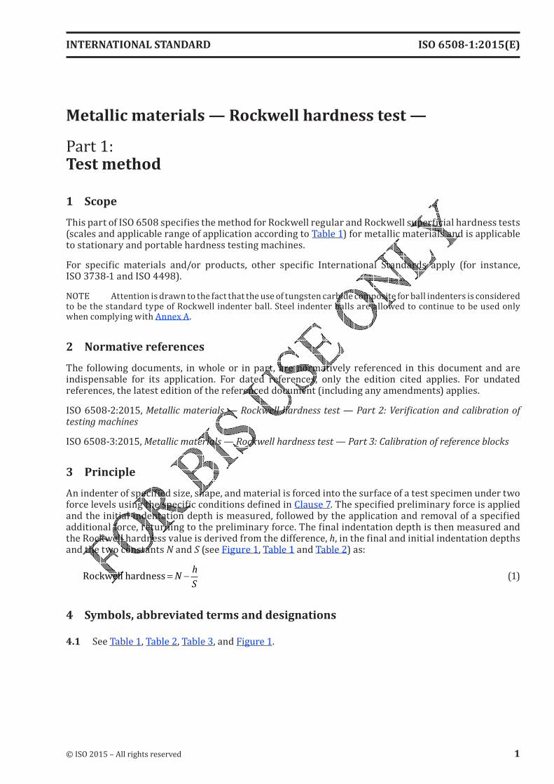
1 ScopeThis part of ISO 6508 specifies the method for Rockwell regular and Rockwell superficial hardness tests (scales and applicable range of application according to Table 1) for metallic materials and is applicable to stationary and portable hardness testing machines.For specific materials and/or products, other specific International Standards apply (for instance, ISO 3738-1 and ISO 4498).
NOTE Attention is drawn to the fact that the use of tungsten carbide composite for ball indenters is considered to be the standard type of Rockwell indenter ball. Steel indenter balls are allowed to continue to be used only when complying with Annex A.
2 Normative referencesThe following documents, in whole or in part, are normatively referenced in this document and are indispensable for its application. For dated references, only the edition cited applies. For undated references, the latest edition of the referenced document (including any amendments) applies.ISO 6508-2:2015, Metallic materials — Rockwell hardness test — Part 2: Verification and calibration of testing machinesISO 6508-3:2015, Metallic materials — Rockwell hardness test — Part 3: Calibration of reference blocks
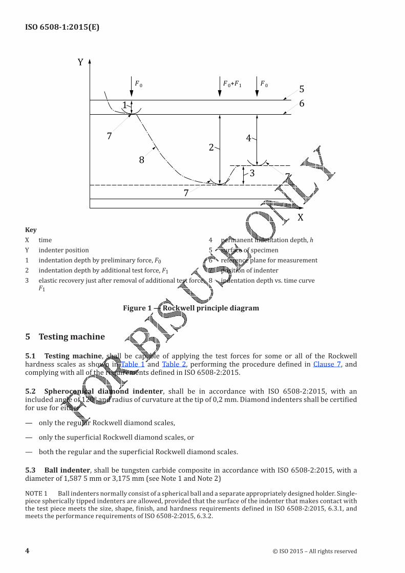
3 PrincipleAn indenter of specified size, shape, and material is forced into the surface of a test specimen under two force levels using the specific conditions defined in Clause 7. The specified preliminary force is applied and the initial indentation depth is measured, followed by the application and removal of a specified additional force, returning to the preliminary force. The final indentation depth is then measured and the Rockwell hardness value is derived from the difference, h, in the final and initial indentation depths and the two constants N and S (see Figure 1, Table 1 and Table 2) as:
Rockwell hardness = −Nh
S (1)
4 Symbols, abbreviated terms and designations
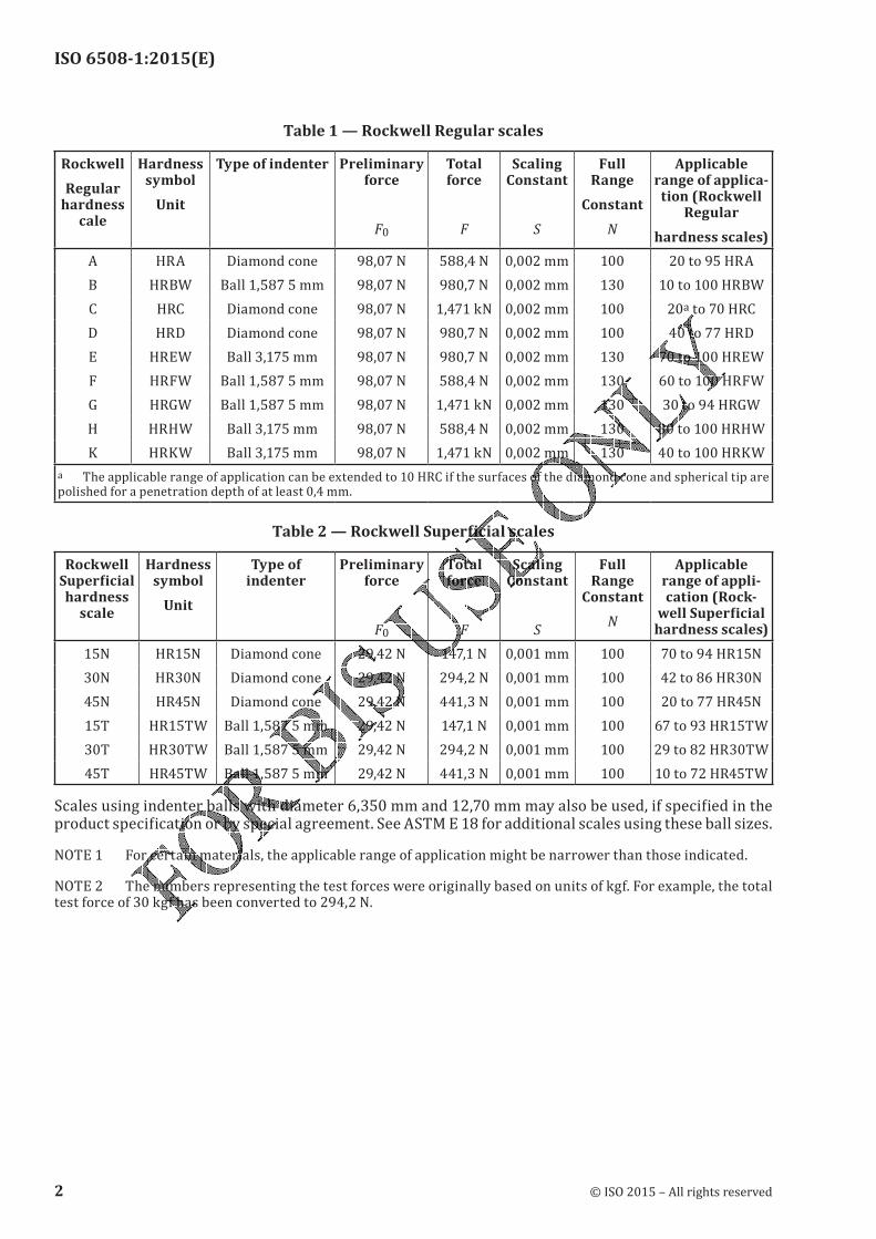
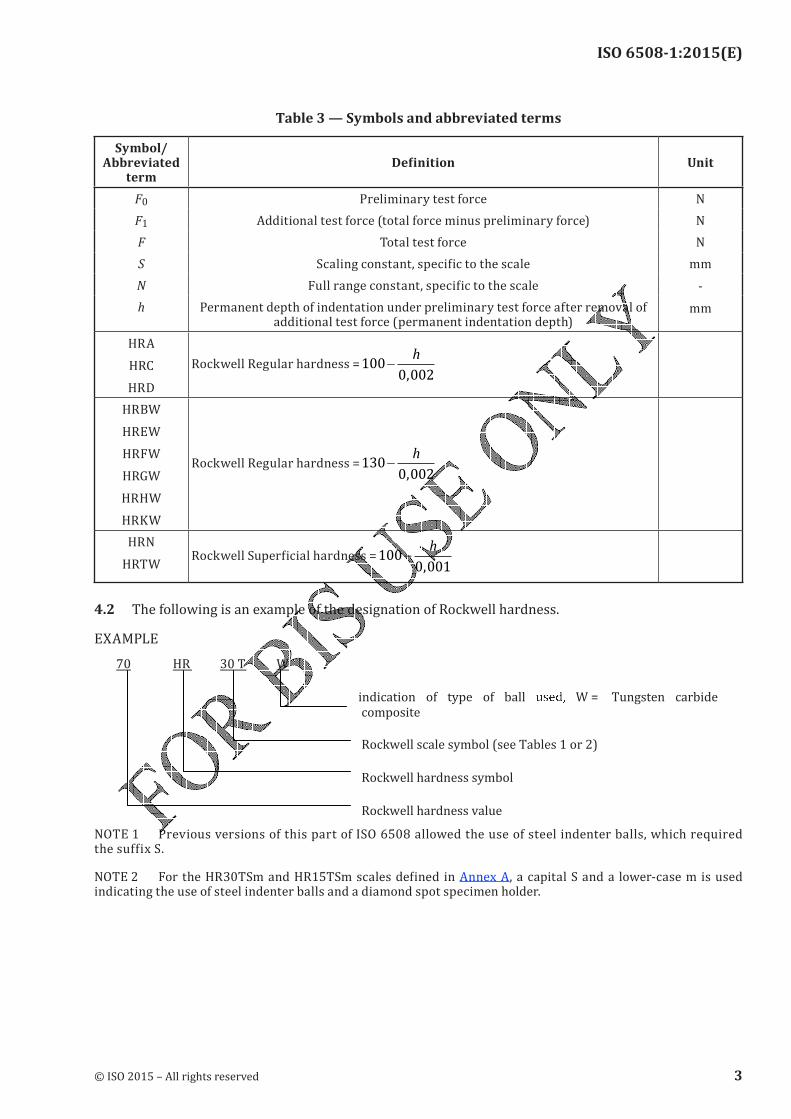
4.1 See Table 1, Table 2, Table 3, and Figure 1.
INTERNATIONAL STANDARD ISO 6508-1:2015(E)
© ISO 2015 – All rights reserved 1
ISO 6508-1:2015(E)
Table 1 — Rockwell Regular scales
Rockwell
Regular hardness
cale
Hardness symbol
Unit
Type of indenter Preliminary force
F0
Total force
F
Scaling Constant
S
Full Range
Constant
N
Applicable range of applica-
tion (Rockwell Regular
hardness scales)
A HRA Diamond cone 98,07 N 588,4 N 0,002 mm 100 20 to 95 HRAB HRBW Ball 1,587 5 mm 98,07 N 980,7 N 0,002 mm 130 10 to 100 HRBWC HRC Diamond cone 98,07 N 1,471 kN 0,002 mm 100 20a to 70 HRC
D HRD Diamond cone 98,07 N 980,7 N 0,002 mm 100 40 to 77 HRD
E HREW Ball 3,175 mm 98,07 N 980,7 N 0,002 mm 130 70 to 100 HREW
F HRFW Ball 1,587 5 mm 98,07 N 588,4 N 0,002 mm 130 60 to 100 HRFW
G HRGW Ball 1,587 5 mm 98,07 N 1,471 kN 0,002 mm 130 30 to 94 HRGW
H HRHW Ball 3,175 mm 98,07 N 588,4 N 0,002 mm 130 80 to 100 HRHW
K HRKW Ball 3,175 mm 98,07 N 1,471 kN 0,002 mm 130 40 to 100 HRKW
a The applicable range of application can be extended to 10 HRC if the surfaces of the diamond cone and spherical tip are polished for a penetration depth of at least 0,4 mm.Table 2 — Rockwell Superficial scales
Rockwell Superficial hardness
scale
Hardness symbol
Unit
Type of indenter
Preliminary force
F0
Total force
F
Scaling Constant
S
Full Range
Constant
N
Applicable range of appli-cation (Rock-
well Superficial hardness scales)
15N HR15N Diamond cone 29,42 N 147,1 N 0,001 mm 100 70 to 94 HR15N
30N HR30N Diamond cone 29,42 N 294,2 N 0,001 mm 100 42 to 86 HR30N
45N HR45N Diamond cone 29,42 N 441,3 N 0,001 mm 100 20 to 77 HR45N
15T HR15TW Ball 1,587 5 mm 29,42 N 147,1 N 0,001 mm 100 67 to 93 HR15TW
30T HR30TW Ball 1,587 5 mm 29,42 N 294,2 N 0,001 mm 100 29 to 82 HR30TW
45T HR45TW Ball 1,587 5 mm 29,42 N 441,3 N 0,001 mm 100 10 to 72 HR45TWScales using indenter balls with diameter 6,350 mm and 12,70 mm may also be used, if specified in the product specification or by special agreement. See ASTM E 18 for additional scales using these ball sizes.NOTE 1 For certain materials, the applicable range of application might be narrower than those indicated.NOTE 2 The numbers representing the test forces were originally based on units of kgf. For example, the total test force of 30 kgf has been converted to 294,2 N.
2 © ISO 2015 – All rights reserved
ISO 6508-1:2015(E)
Table 3 — Symbols and abbreviated terms
Symbol/ Abbreviated
termDefinition Unit
F0 Preliminary test force N
F1 Additional test force (total force minus preliminary force) N
F Total test force N
S Scaling constant, specific to the scale mm
-
mm
N Full range constant, specific to the scaleh Permanent depth of indentation under preliminary test force after removal of
additional test force (permanent indentation depth)
HRA
HRC
HRD
Rockwell Regular hardness =1000 002
−h
,HRBWHREW
HRFW
HRGW
HRHW
HRKW
Rockwell Regular hardness =1300 002
−h
,
HRN
HRTWRockwell Superficial hardness =100
0 001−
h
,
4.2 The following is an example of the designation of Rockwell hardness.EXAMPLE7 0 HR 30 T W
indication of type of ball u���� W = Tungsten carbide
composite
Rockwell scale symbol (see Tables 1 or 2)
Rockwell hardness symbol
NOTE 1 Previous versions of this part of ISO 6508 allowed the use of steel indenter balls, which required the suffix S.NOTE 2 For the HR30TSm and HR15TSm scales defined in Annex A, a capital S and a lower-case m is used indicating the use of steel indenter balls and a diamond spot specimen holder.
© ISO 2015 – All rights reserved 3
ISO 6508-1:2015(E)
Y
F0 F0+F1 F05
6
42
3 7
8
1
7
7
Key
X time 4 permanent indentation depth, hY indenter position 5 surface of specimen
1 indentation depth by preliminary force, F0 6 reference plane for measurement
2 indentation depth by additional test force, F1 7 position of indenter
3 elastic recovery just after removal of additional test force, F1
8 indentation depth vs. time curve
Figure 1 — Rockwell principle diagram
5 Testing machine
5.1 Testing machine, shall be capable of applying the test forces for some or all of the Rockwell hardness scales as shown in Table 1 and Table 2, performing the procedure defined in Clause 7, and complying with all of the requirements defined in ISO 6508-2:2015.5.2 Spheroconical diamond indenter, shall be in accordance with ISO 6508-2:2015, with an included angle of 120° and radius of curvature at the tip of 0,2 mm. Diamond indenters shall be certified for use for either— only the regular Rockwell diamond scales,— only the superficial Rockwell diamond scales, or— both the regular and the superficial Rockwell diamond scales.5.3 Ball indenter, shall be tungsten carbide composite in accordance with ISO 6508-2:2015, with a diameter of 1,587 5 mm or 3,175 mm (see Note 1 and Note 2)NOTE 1 Ball indenters normally consist of a spherical ball and a separate appropriately designed holder. Single-piece spherically tipped indenters are allowed, provided that the surface of the indenter that makes contact with the test piece meets the size, shape, finish, and hardness requirements defined in ISO 6508-2:2015, 6.3.1, and meets the performance requirements of ISO 6508-2:2015, 6.3.2.
4 © ISO 2015 – All rights reserved
ISO 6508-1:2015(E)
NOTE 2 Attention is drawn to the fact that the use of tungsten carbide composite for ball indenters is the standard type of Rockwell indenter ball. Steel indenter balls can only be used when performing Rockwell HR30TSm and HR15TSm tests according to Annex A.
6 Test piece
6.1 The test shall be carried out on a surface which is smooth and even, free from oxide scale, foreign matter and, in particular, completely free from lubricants, unless specified otherwise in product or materials standards. An exception is made for reactive metals, such as titanium, which might adhere to the indenter. In such situations, a suitable lubricant such as kerosene may be used. The use of a lubricant shall be reported on the test report.
6.2 Preparation shall be carried out in such a way that any alteration of the surface hardness due to excessive heating or cold-working for example, is minimized. This shall be taken into account, particularly in the case of low-depth indentations.
6.3 The thickness of the test piece, or of the layer under test (minimum values are given in Annex B), shall be at least 10 times the permanent indentation depth for diamond indenters and 15 times the permanent indentation depth for ball indenters, unless it can be demonstrated that the use of a thinner test piece does not affect the measured hardness value. In general, no deformation should be visible on the back of the test piece after the test, although not all such marking is indicative of a bad test.See Annex A for special requirements for testing very thin sheet metal using the HR30TSm and HR15TSm scales.
6.4 For tests on convex cylindrical surfaces and spherical surfaces, see 7.11.
7 Procedure
7.1 This part of ISO 6508 has been developed with a laboratory temperature requirement of 10°C to 35°C. For environments outside the stated requirement, it is the responsibility of the testing laboratory to assess the impact on testing data produced with testing machines operated in such environments. When testing is performed outside the recommended temperature limits of 10 °C to 35 °C, the temperature shall be recorded and reported.NOTE If significant temperature gradients are present during testing and/or calibration, measurement uncertainty can increase and out of tolerance conditions can occur.7.2 The daily verification defined in Annex E shall be performed before the first test of each day for each scale to be used. The condition of diamond indenters should be checked according to Annex F.
7.3 After each change, or removal and replacement, of the indenter, indenter ball, or test piece support, perform at least two tests and discard the results, then determine that the indenter and the test piece support are correctly mounted in the machine by performing the daily verification process defined in Annex E.
7.4 The diamond or ball indenter shall have been the indenter used during the last indirect verification. If the indenter was not used during the indirect verification and is being used for the first time, it shall be verified in accordance with the daily verification given in Annex E using at least two test blocks (one from the low and high ranges as defined in ISO 6508-2:2015, Table 1) for each Rockwell scale that is normally used. This does not apply to replacing a ball.
© ISO 2015 – All rights reserved 5
ISO 6508-1:2015(E)
7.5 The test piece shall be placed on a rigid support and supported in such a manner that the surface to be indented is in a plane normal to the axis of the indenter and the line of the indenting force, as well as to avoid a displacement of the test piece.Products of cylindrical shape shall be suitably supported, for example, on centering V-block or double cylinders made of material with a Rockwell hardness of at least 60 HRC. Special attention shall be given to the correct seating, bearing, and alignment of the indenters, the test piece, the centering V-blocks, and the specimen holder of the testing machine, since any perpendicular misalignment might result in incorrect results.
7.6 Bring the indenter into contact with the test surface and apply the preliminary test force, F0, without shock, vibration, oscillation, or overload. The preliminary force application time should not exceed 2 s. The duration of the preliminary test force, F0, shall be 3 +−
12
s.NOTE The requirements for the time durations are given with asymmetric limits.EXAMPLE 3 +−
12
s indicates that 3 s is the ideal time duration, with an acceptable range of not less than 1 s (3 s - 2 s) to not more than 4 s (3 s + 1 s).
7.7 Measure the initial indentation depth. For many manual (dial-indicator) machines, this is done by setting the indicating dial to its set-point or zero position. For many automatic (digital) machines, the depth measurement is made automatically without the user’s input and might not be displayed.7.8 Apply the additional force F1 without shock, vibration, oscillation, or overload to increase the force from F0 to the total force, F. For the regular Rockwell scale tests, apply the additional test force, F1, in not less than 1 s and not more than 8 s. For all HRN and HRTW Rockwell superficial test scales, apply the additional test force, F1, in less than or equal to 4 s. It is recommended to perform the same test cycle used during indirect verification.NOTE There is evidence that some materials might be sensitive to the rate of straining which causes small changes in the value of the yield stress. The corresponding effect on the termination of the formation of an indentation can make an alteration in the hardness value.
7.9 The total test force, F, shall be maintained for a duration of 5 +−
13
s. Remove the additional test force, F1, and, while the preliminary test force, F0, is maintained, after 4 +
−
13
s, the final reading shall be made.As an exception for test materials exhibiting excessive plastic flow (indentation creep) during the application of the total test force, special considerations might be necessary since the indenter will continue to penetrate. When materials require the use of a total force duration that exceeds the 6 s allowed by the tolerances, the actual extended total force duration used shall be reported following the test results (for example, 65 HRF/10 s).7.10 Measure the final indentation depth while the preliminary test force is applied. The Rockwell hardness number is calculated from the permanent indentation depth, h, using the formula given in Formula (1) and the information given in Table 1, Table 2, and Table 3. For most Rockwell hardness machines, the depth measurement is made in a manner that automatically calculates and displays the Rockwell hardness number.
The derivation of the Rockwell hardness number is illustrated in Figure 1.
7.11 For tests on convex cylindrical surfaces and spherical surfaces, the corrections given in Annex C (Table C.1, Table C.2, Table C.3 or Table C.4) and in Annex D (Table D.1) shall be applied. The correction values shall be reported on the test report.In the absence of corrections for tests on concave surfaces, tests on such surfaces should be the subject of special agreement.
6 © ISO 2015 – All rights reserved
ISO 6508-1:2015(E)
7.12 Throughout the test, the apparatus shall be protected from shock or vibration.7.13 The distance between the centres of two adjacent indentations shall be at least three times the diameter of the indentation. The distance from the centre of any indentation to an edge of the test piece shall be at least two and a half times the diameter of the indentation.
8 Uncertainty of the resultsA complete evaluation of the uncertainty should be done according to ISO/IEC Guide 98-3.[3]Independent of the type of sources, for hardness, there are two possibilities for the determination of the uncertainty.— One possibility is based on the evaluation of all relevant sources appearing during a direct calibration. As a reference, an EURAMET Guide CG-16[4] is available.— The other possibility is based on indirect calibration using a hardness reference block (abbreviated as CRM certified reference material).[2][3][4][5] A guideline for the determination is given in Annex G.
9 Test reportThe laboratory shall record at least the following information and that information shall be included in the test report, unless agreed by the parties concerned:a) a reference to this part of ISO 6508 (i.e. ISO 6508-1);b) all details necessary for the complete identification of the test piece, including the curvature of the
test surface;c) the test temperature, if it is not within the limits of 10 °C to 35 °C;d) the hardness result in the format defined in 4.2;e) all operations not specified in this part of ISO 6508, or regarded as optional;f) details of any occurrence which might have affected the result;g) the actual extended total force duration time used, if greater than the 6 s allowed by the tolerances;h) the date the test was performed;i) if conversion to another hardness scale is also performed, the basis and method of this conversion shall be specified (see ISO 18265).10 Conversions to other hardness scales or tensile strength valuesThere is no general process for accurately converting Rockwell hardness into other scales, or hardness into tensile strength. Such conversions, therefore, should be avoided, unless a reliable basis for conversion can be obtained by comparison tests (see also ISO 18265).
© ISO 2015 – All rights reserved 7
ISO 6508-1:2015(E)
Annex A (normative)
Special HR30TSm and HR15TSm test for thin products
A.1 GeneralThis test is applicable to thin sheet metal products having a maximum thickness of 0,6 mm to the minimum thickness indicated in the product standards, and of a maximum hardness of 82 HR30TSm or 93 HR15TSm. The product standard shall specify when the Special HR30TSm or HR15TSm hardness test is to be applied.This test is carried out under conditions similar to those in the HR30TW or HR15TW test defined in this part of ISO 6508. The appearance of deformation on the bottom of the test pieces below the indent is permitted.
NOTE 1 The Sm in the scale designations indicates that a steel ball indenter and a diamond spot specimen holder are used for this testing.NOTE 2 Prior to testing, hardness tests should be made on thin sheet samples of a known hardness to verify that the specimen holder surface does not affect the measurement results.The following requirements shall be met, in addition to those specified in this part of ISO 6508.A.2 Ball indenterA hardened steel ball indenter, that meets the requirements of ISO 6508-2:2015, with a diameter of 1,587 5 mm shall be used for this testing.A.3 Test piece supportThe test piece support shall comprise a polished and smooth flat diamond surface approximately 4,5 mm in diameter. This support surface shall be approximately centred on the axis of the indenter and shall be perpendicular to it. Care shall be taken to ensure that it is seated correctly on the machine table.A.4 Test piece preparationIf it is necessary to remove material from the test piece, this should be done on both sides of the test piece. Care shall be taken to ensure that this process does not change the condition of the base metal, for example, by heating or work hardening. The base metal shall not be made thinner than the minimum allowable thickness.
A.5 Position of the test pieceThe distance between the centres of two adjacent indentations or between the centre of one of the indentations and the edge of the test piece shall be at least 5 mm, unless otherwise specified.
8 © ISO 2015 – All rights reserved
ISO 6508-1:2015(E)
Annex B (normative)
Minimum thickness of the test piece in relation to the Rockwell
hardness
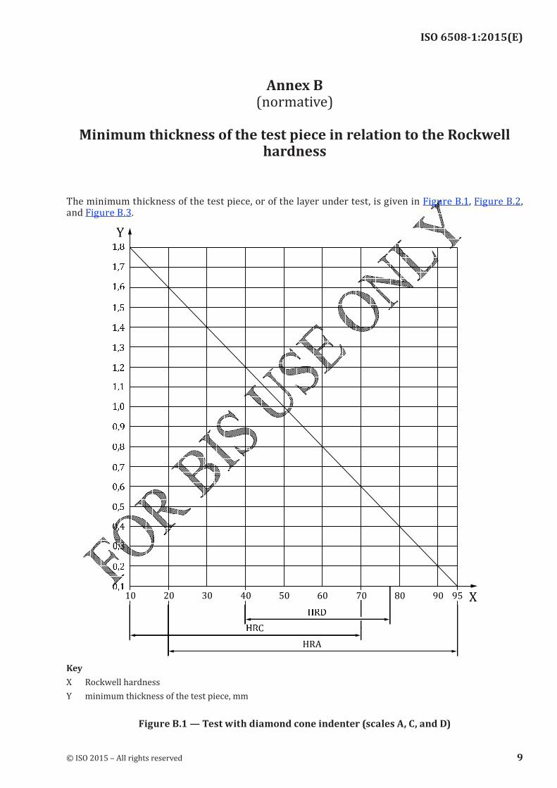
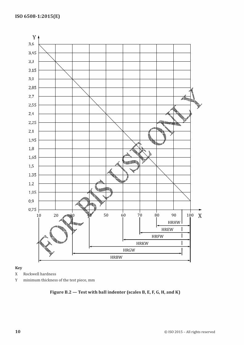
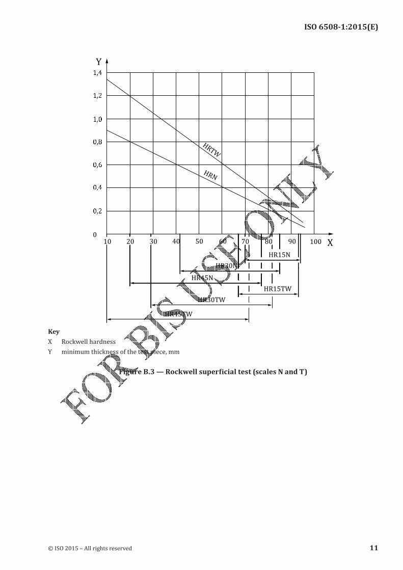
The minimum thickness of the test piece, or of the layer under test, is given in Figure B.1, Figure B.2, and Figure B.3.
H��
H�C
908070605030
1��
1��
1�
1�
1��
1�1
1��
��0
��
���
���
���
��
��
���
4020
Y
X9510
1��
��1
1�
Key
X Rockwell hardness
Y minimum thickness of the test piece, mmFigure B.1 — Test with diamond cone indenter (scales A, C, and D)
© ISO 2015 – All rights reserved 9
ISO 6508-1:2015(E)
X
Y
100
����
���
����
���
����
���
����
���
����
���
����
��2
����
���
����
���
����
���
20 30 40 50 60 70 80 9010
��2�
���
HRHW
HREW
HRFW
HRKW
HRGW
Key
X Rockwell hardness
Y minimum thickness of the test piece, mmFigure B.2 — Test with ball indenter (scales B, E, F, G, H, and K)
10 © ISO 2015 – All rights reserved
ISO 6508-1:2015(E)
X
Y
HRN
HRTW
10 20 30 40 50 60 70 80 90 100
���
���
���
���
���
���
���
0
HR30TW
HR15TW
HR45N
HR30N
HR15N
Key
X Rockwell hardness
Y minimum thickness of the test piece, mmFigure B.3 — Rockwell superficial test (scales N and T)
© ISO 2015 – All rights reserved 11
ISO 6508-1:2015(E)
Annex C (normative)
Corrections to be added to Rockwell hardness values obtained on
convex cylindrical surfaces
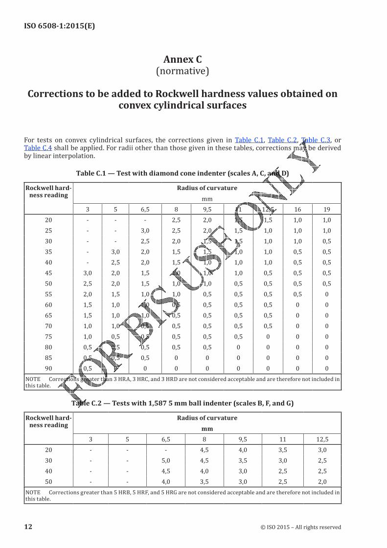
For tests on convex cylindrical surfaces, the corrections given in Table C.1, Table C.2, Table C.3, or Table C.4 shall be applied. For radii other than those given in these tables, corrections may be derived by linear interpolation.
Table C.1 — Test with diamond cone indenter (scales A, C, and D)
Rockwell hard-ness reading
Radius of curvature
mm
3 5 6,5 8 9,5 11 12,5 16 19
20 - - - 2,5 2,0 1,5 1,5 1,0 1,025 - - 3,0 2,5 2,0 1,5 1,0 1,0 1,030 - - 2,5 2,0 1,5 1,5 1,0 1,0 0,535 - 3,0 2,0 1,5 1,5 1,0 1,0 0,5 0,540 - 2,5 2,0 1,5 1,0 1,0 1,0 0,5 0,545 3,0 2,0 1,5 1,0 1,0 1,0 0,5 0,5 0,550 2,5 2,0 1,5 1,0 1,0 0,5 0,5 0,5 0,555 2,0 1,5 1,0 1,0 0,5 0,5 0,5 0,5 0
60 1,5 1,0 1,0 0,5 0,5 0,5 0,5 0 0
65 1,5 1,0 1,0 0,5 0,5 0,5 0,5 0 0
70 1,0 1,0 0,5 0,5 0,5 0,5 0,5 0 0
75 1,0 0,5 0,5 0,5 0,5 0,5 0 0 0
80 0,5 0,5 0,5 0,5 0,5 0 0 0 0
85 0,5 0,5 0,5 0 0 0 0 0 0
90 0,5 0 0 0 0 0 0 0 0NOTE Corrections greater than 3 HRA, 3 HRC, and 3 HRD are not considered acceptable and are therefore not included in this table.
Table C.2 — Tests with 1,587 5 mm ball indenter (scales B, F, and G)
Rockwell hard-ness reading
Radius of curvature
mm
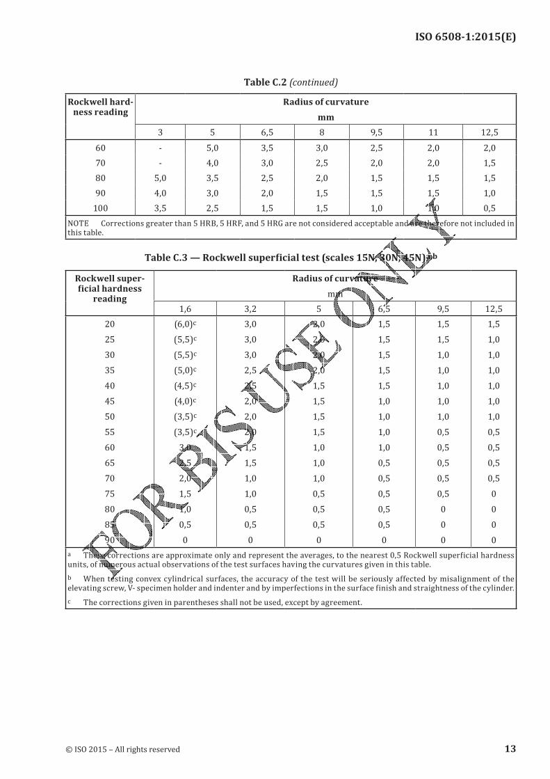
3 5 6,5 8 9,5 11 12,520 - - - 4,5 4,0 3,5 3,030 - - 5,0 4,5 3,5 3,0 2,540 - - 4,5 4,0 3,0 2,5 2,550 - - 4,0 3,5 3,0 2,5 2,0NOTE Corrections greater than 5 HRB, 5 HRF, and 5 HRG are not considered acceptable and are therefore not included in
this table.
12 © ISO 2015 – All rights reserved
ISO 6508-1:2015(E)
Rockwell hard-ness reading
Radius of curvature
mm
3 5 6,5 8 9,5 11 12,560 - 5,0 3,5 3,0 2,5 2,0 2,070 - 4,0 3,0 2,5 2,0 2,0 1,580 5,0 3,5 2,5 2,0 1,5 1,5 1,590 4,0 3,0 2,0 1,5 1,5 1,5 1,0
100 3,5 2,5 1,5 1,5 1,0 1,0 0,5NOTE Corrections greater than 5 HRB, 5 HRF, and 5 HRG are not considered acceptable and are therefore not included in this table.
Table C.3 — Rockwell superficial test (scales 15N, 30N, 45N)a,b
Rockwell super-ficial hardness
reading
Radius of curvature
mm1,6 3,2 5 6,5 9,5 12,520
25
30
35
40
45
50
55
60
65
70
75
80
85
90
(6,0)c(5,5)c(5,5)c(5,0)c(4,5)c(4,0)c(3,5)c(3,5)c3,02,52,01,51,00,50
3,03,03,02,52,52,02,02,01,51,51,01,00,50,50
2,02,02,02,01,51,51,51,51,01,01,00,50,50,50
1,51,51,51,51,51,01,01,01,00,50,50,50,50,50
1,51,51,01,01,01,01,00,50,50,50,50,50
0
0
1,51,01,01,01,01,01,00,50,50,50,50
0
0
0
a These corrections are approximate only and represent the averages, to the nearest 0,5 Rockwell superficial hardness units, of numerous actual observations of the test surfaces having the curvatures given in this table.b When testing convex cylindrical surfaces, the accuracy of the test will be seriously affected by misalignment of the elevating screw, V- specimen holder and indenter and by imperfections in the surface finish and straightness of the cylinder.c The corrections given in parentheses shall not be used, except by agreement.
Table C.2 (continued)
© ISO 2015 – All rights reserved 13
ISO 6508-1:2015(E)
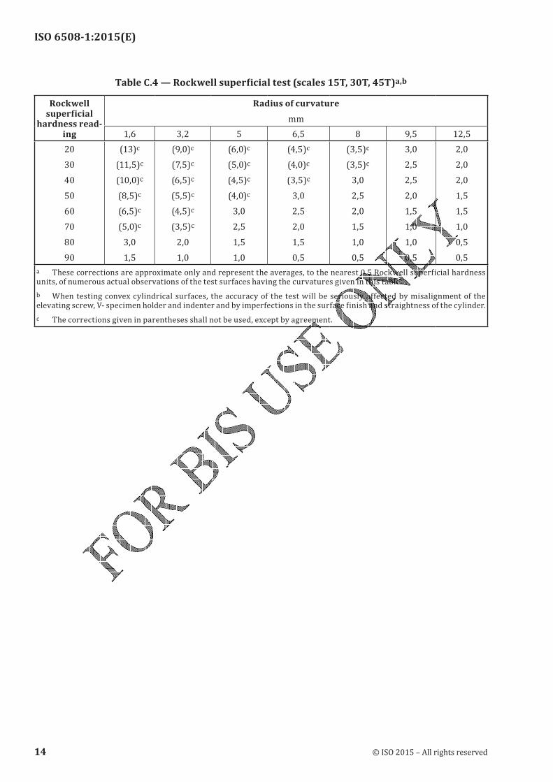
Table C.4 — Rockwell superficial test (scales 15T, 30T, 45T)a,b
Rockwell superficial
hardness read-ing
Radius of curvature
mm1,6 3,2 5 6,5 8 9,5 12,520
30
40
50
60
70
80
90
(13)c(11,5)c(10,0)c(8,5)c(6,5)c(5,0)c3,01,5
(9,0)c(7,5)c(6,5)c(5,5)c(4,5)c(3,5)c2,01,0
(6,0)c(5,0)c(4,5)c(4,0)c3,02,51,51,0
(4,5)c(4,0)c(3,5)c3,02,52,01,50,5
(3,5)c(3,5)c3,02,52,01,51,00,5
3,02,52,52,01,51,01,00,5
2,02,02,01,51,51,00,50,5a These corrections are approximate only and represent the averages, to the nearest 0,5 Rockwell superficial hardness units, of numerous actual observations of the test surfaces having the curvatures given in this table.b When testing convex cylindrical surfaces, the accuracy of the test will be seriously affected by misalignment of the elevating screw, V- specimen holder and indenter and by imperfections in the surface finish and straightness of the cylinder.c The corrections given in parentheses shall not be used, except by agreement.
14 © ISO 2015 – All rights reserved
ISO 6508-1:2015(E)
Annex D (normative)
Corrections to be added to Rockwell hardness C scale values
obtained on spherical test surfaces of various diameters
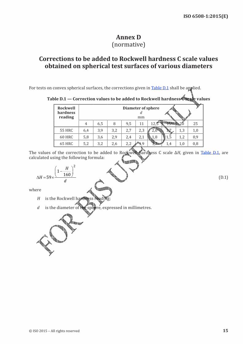
For tests on convex spherical surfaces, the corrections given in Table D.1 shall be applied.
Table D.1 — Correction values to be added to Rockwell hardness C scale values
Rockwell hardness reading
Diameter of sphere d
mm
4 6,5 8 9,5 11 12,5 15 20 25
55 HRC 6,4 3,9 3,2 2,7 2,3 2,0 1,7 1,3 1,060 HRC 5,8 3,6 2,9 2,4 2,1 1,8 1,5 1,2 0,965 HRC 5,2 3,2 2,6 2,2 1,9 1,7 1,4 1,0 0,8The values of the correction to be added to Rockwell hardness C scale ΔH, given in Table D.1, are
calculated using the following formula:
∆ = ×
−
H
H
d59
1160
2
(D.1)
where
H is the Rockwell hardness reading;
d is the diameter of the sphere, expressed in millimetres.
© ISO 2015 – All rights reserved 15
ISO 6508-1:2015(E)
Annex E (normative)
Daily Verification Procedure
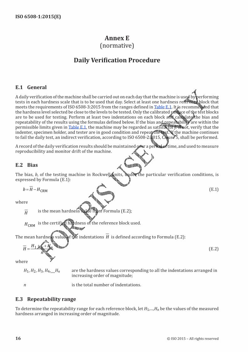
E.1 GeneralA daily verification of the machine shall be carried out on each day that the machine is used by performing tests in each hardness scale that is to be used that day. Select at least one hardness reference block that meets the requirements of ISO 6508-3:2015 from the ranges defined in Table E.1. It is recommended that the hardness level selected be close to the levels to be tested. Only the calibrated surface of the test blocks are to be used for testing. Perform at least two indentations on each block and calculate the bias and repeatability of the results using the formulas defined below. If the bias and repeatability are within the permissible limits given in Table E.1, the machine may be regarded as satisfactory. If not, verify that the indenter, specimen holder, and tester are in good condition and repeat the test. If the machine continues to fail the daily test, an indirect verification, according to ISO 6508-2:2015, Clause 5, shall be performed.A record of the daily verification results should be maintained over a period of time, and used to measure reproducibility and monitor drift of the machine.E.2 BiasThe bias, b, of the testing machine in Rockwell units, under the particular verification conditions, is expressed by Formula (E.1):
b H H= − CRM (E.1)
where
H is the mean hardness value from Formula (E.2);
HCRM is the certified hardness of the reference block used.The mean hardness value of the indentations H is defined according to Formula (E.2):
HH H
n
n=+ +1 ...
(E.2)
where
H1, H2, H3, H4,,,,,,Hn are the hardness values corresponding to all the indentations arranged in increasing order of magnitude;
n is the total number of indentations.
E.3 Repeatability rangeTo determine the repeatability range for each reference block, let H1,…,Hn be the values of the measured hardness arranged in increasing order of magnitude.
16 © ISO 2015 – All rights reserved
ISO 6508-1:2015(E)
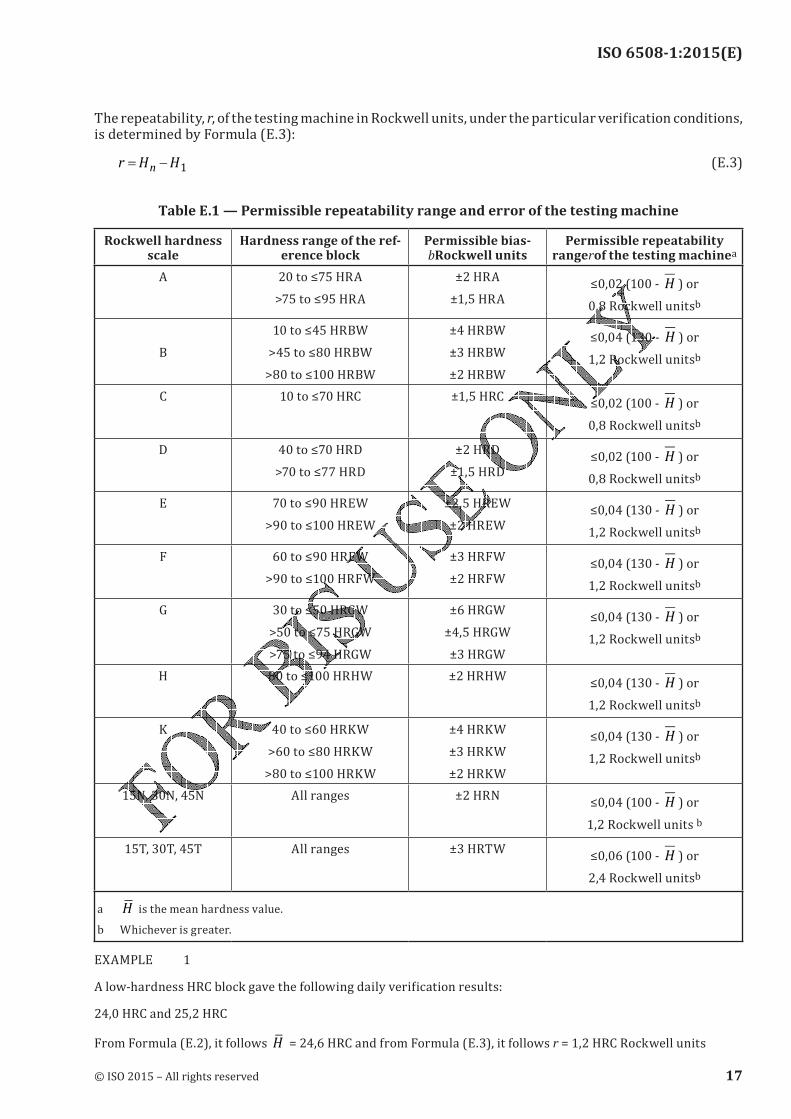
The repeatability, r, of the testing machine in Rockwell units, under the particular verification conditions, is determined by Formula (E.3):r H H
n= − 1 (E.3)
Table E.1 — Permissible repeatability range and error of the testing machine
Rockwell hardness scale
Hardness range of the ref-erence block
Permissible bias-bRockwell units
Permissible repeatability rangerof the testing machinea
A 20 to ≤75 HRA>75 to ≤95 HRA ±2 HRA±1,5 HRA ≤0,02 (100 - H ) or0,8 Rockwell unitsb
B 10 to ≤45 HRBW>45 to ≤80 HRBW>80 to ≤100 HRBW±4 HRBW±3 HRBW±2 HRBW
≤0,04 (130 - H ) or1,2 Rockwell unitsb
C 10 to ≤70 HRC ±1,5 HRC ≤0,02 (100 - H ) or0,8 Rockwell unitsb
D 40 to ≤70 HRD>70 to ≤77 HRD ±2 HRD±1,5 HRD ≤0,02 (100 - H ) or0,8 Rockwell unitsb
E 70 to ≤90 HREW>90 to ≤100 HREW ±2,5 HREW±2 HREW
≤0,04 (130 - H ) or1,2 Rockwell unitsb
F 60 to ≤90 HRFW>90 to ≤100 HRFW ±3 HRFW
±2 HRFW≤0,04 (130 - H ) or1,2 Rockwell unitsb
G 30 to ≤50 HRGW>50 to ≤75 HRGW>75 to ≤94 HRGW±6 HRGW±4,5 HRGW±3 HRGW
≤0,04 (130 - H ) or1,2 Rockwell unitsb
H 80 to ≤100 HRHW ±2 HRHW ≤0,04 (130 - H ) or1,2 Rockwell unitsb
K 40 to ≤60 HRKW>60 to ≤80 HRKW>80 to ≤100 HRKW±4 HRKW
±3 HRKW
±2 HRKW
≤0,04 (130 - H ) or1,2 Rockwell unitsb
15N, 30N, 45N All ranges ±2 HRN ≤0,04 (100 - H ) or1,2 Rockwell units b15T, 30T, 45T All ranges ±3 HRTW ≤0,06 (100 - H ) or2,4 Rockwell unitsb
a H is the mean hardness value.
b Whichever is greater.EXAMPLE 1A low-hardness HRC block gave the following daily verification results:24,0 HRC and 25,2 HRCFrom Formula (E.2), it follows H = 24,6 HRC and from Formula (E.3), it follows r = 1,2 HRC Rockwell units
© ISO 2015 – All rights reserved 17
ISO 6508-1:2015(E)
From Table E.1, for the HRC scale, the permissible repeatability range at HRC 24,6 = 0,02 (100 − 24,6) = 1,51 HRC Rockwell units. This is greater than 0,8 HRC Rockwell units, therefore, the permissible repeatability range of the testing machine for this reference block is 1,51 HRC Rockwell units.Since r = 1,2 HRC Rockwell units, the repeatability of the testing machine is acceptable.EXAMPLE 2A high-hardness HRC block gave the following daily verification results:63,1 HRC and 63,9 HRCFrom Formula (E.2), it follows H = 63,5 HRC and from Formula (E.3), it follows r = 0,8 HRC Rockwell units.From Table E.1, for the HRC scale, the permissible repeatability range at HRC 63,5 = 0,02 (100 – 63,5) = 0,73 HRC Rockwell units. This is less than 0,8 HRC Rockwell units, therefore, the permissible repeatability range of the testing machine for this reference block is 0,8 HRC Rockwell units.Since r = 0,8 HRC Rockwell units, the repeatability of the testing machine is acceptable.
18 © ISO 2015 – All rights reserved
ISO 6508-1:2015(E)
Annex F (normative)
Inspection of diamond indenters
Experience has shown that a number of initially satisfactory indenters can become defective after use for a comparatively short time. This is due to small cracks, pits, or other flaws in the surface. If such faults are detected in time, many indenters can be reclaimed by regrinding. If not, any small defects on the surface rapidly worsen and make the indenter useless. Therefore, the condition of indenters should be checked initially and at frequent intervals using appropriate optical devices (microscope, magnifying glass, etc.)— the verification of the indenter is no longer valid when the indenter shows defects;— Reground or otherwise repaired indenters shall be verified in accordance with the requirements of ISO 6508-2:2015.
© ISO 2015 – All rights reserved 19

ISO 6508-1:2015(E)
Annex G (informative)
Uncertainty of the measured hardness values
G.1 General requirementsMeasurement uncertainty analysis is a useful tool to help determine sources of error and to understand differences in test results. This Annex gives guidance on uncertainty estimation but the methods contained are for information only, unless specifically instructed otherwise by the customer. Most product specifications have tolerances that have been developed over the past years based mainly on the requirements of the product but also, in part, on the performance of the machine used to make the hardness measurement. These tolerances therefore incorporate a contribution due to the uncertainty of the hardness measurement and it would be inappropriate to make any further allowance for this uncertainty by, for example, reducing the specified tolerance by the estimated uncertainty of the hardness measurement. In other words, where a product specification states that the hardness of an item shall be higher or lower than a certain value, this should be interpreted as simply specifying that the calculated hardness value(s) shall meet this requirement, unless specifically stated otherwise in the product standard. However, there might be special circumstances where reducing the tolerance by the measurement uncertainty is appropriate. This should only be done by agreement of the parties involved.The approach for determining uncertainty presented in this Annex considers only those uncertainties associated with the overall measurement performance of the hardness testing machine with respect to the hardness reference blocks (abbreviated as CRM below). These performance uncertainties reflect the combined effect to all the separate uncertainties. Because of this approach, it is important that the individual machine components are operating within the tolerances. It is strongly recommended that this procedure should be applied for a maximum of one year after the successful passing of a verification and calibration.
Annex I shows the four-level structure of the metrological chain necessary to define and disseminate hardness scales. The chain starts at the international level using international definitions of the various hardness scales to carry out international intercomparisons. A number of primary hardness standard machines at the national level “produce” primary hardness reference blocks for the calibration laboratory level. Naturally, direct calibration and the verification of these machines should be at the highest possible accuracyG.2 General procedureThis procedure calculates an expanded uncertainty, U, associated with the measured hardness value. Two different approaches to this calculation are given in Table G.1 and Table G.2, together with details of the symbols used. In both cases, a number of uncorrelated standard uncertainty sources are combined by the Root-Sum-Square (RSS) method and then multiplied by the coverage factor k = 2. In one approach, the uncertainty contribution from a systematic source is then added arithmetically to this value – in the other approach, a correction is made to the measurement resulting to compensating for this systematic component.NOTE This uncertainty approach makes no allowance for any possible drift in the machine performance subsequent to its last calibration, as it assumes that any such changes will be insignificant in magnitude. As such, most of this analysis could be performed immediately after the machine’s calibration and the results included in the machine’s calibration certificate.
20 © ISO 2015 – All rights reserved
ISO 6508-1:2015(E)
G.3 Bias of the machineThe bias, b, of a hardness testing machine (also termed ‘error’) is derived from the difference between— the certified calibration value of the hardness reference block, and— the mean hardness value of the five indentations made in the hardness reference block during calibration of the hardness testing machine,and can be implemented in different ways into the determination of uncertainty.G.4 Procedures for calculating uncertainty: Hardness measurement values
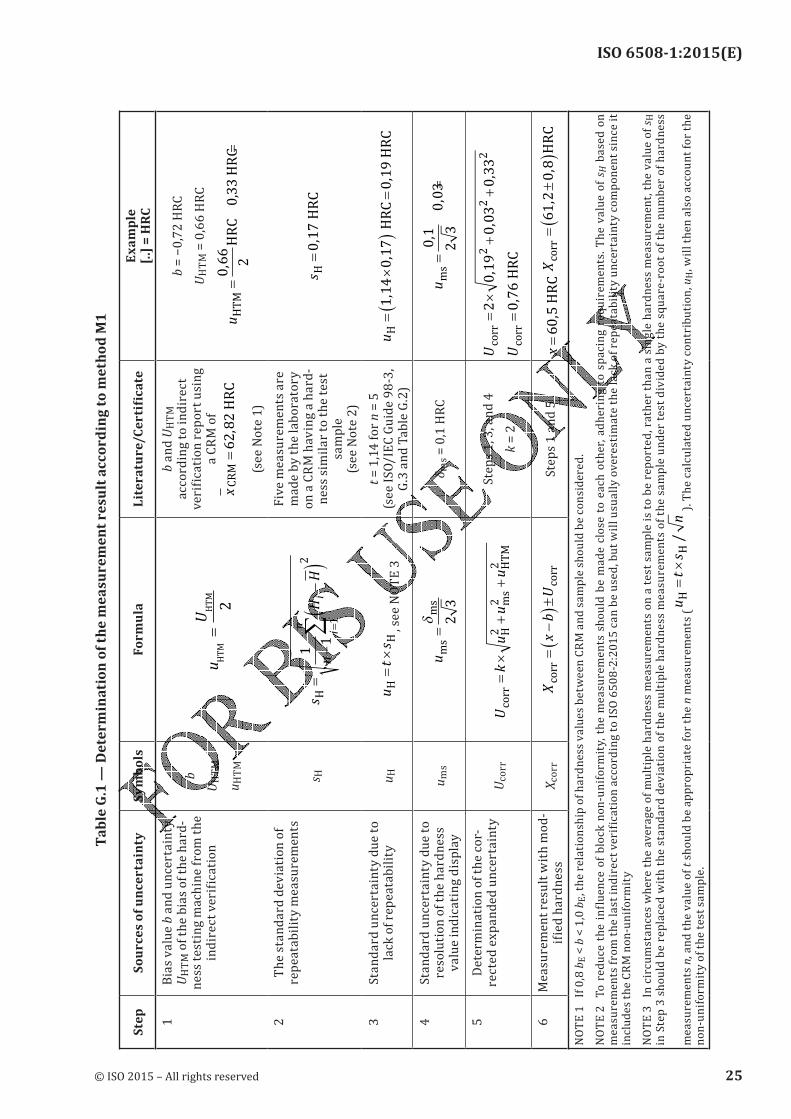
G.4.1 GeneralTwo methods are given for determining the uncertainty of hardness measurements:— Method M1: accounts for the systematic bias of the hardness machine in two different ways;— Method M2: allows the determination of uncertainty without having to consider the magnitude of the systematic bias.Additional information on calculating hardness uncertainties can be found in the literature.[3][4]NOTE In this Annex, the abbreviation “CRM” stands for “Certified Reference Material”. In hardness testing standards, certified reference material is equivalent to the hardness reference block, i.e. a piece of material with a certified value and associated uncertainty.G.4.2 Procedure with bias (method M1)The method M1 procedure for the determination of measurement uncertainty is explained in Table G.1.The measurement bias, b, of the hardness testing machine can be expected to be a systematic effect. In ISO/IEC Guide 98-3,[3] it is recommended that a correction be used to compensate for systematic effects, and this is the basis of M1. The result of using this method is either all determined hardness values have to be reduced by b or the uncertainty Ucorr has to be increased by b. The procedure for the determination of Ucorr is explained in Table G.1.[6][7]The combined expanded measurement uncertainty for a single hardness measurement is calculated as:
U k u u u= × + +H ms HTM
2 2 2 (G.1)
where
uH is a contribution to the measurement uncertainty due to the lack of measurement repeata-bility of the hardness testing machine;ums is a contribution to the measurement uncertainty due to the resolution of the hardness test-
ing machine;
uHTM is a contribution to the measurement uncertainty due to the standard uncertainty of the bias, b, measurement generated by the hardness testing machine (this value is reported as a result of the indirect verification defined in ISO 6508-2:2015 and is defined according to Formula (G.2):
© ISO 2015 – All rights reserved 21
ISO 6508-1:2015(E)
u u u uHTM CRM HCRM ms
= + +2 2 2 (G.2)
where
uCRM is the contribution to the measurement uncertainty due to the calibration uncertainty of the certified value of the CRM according to the calibration certificate for k = 1;
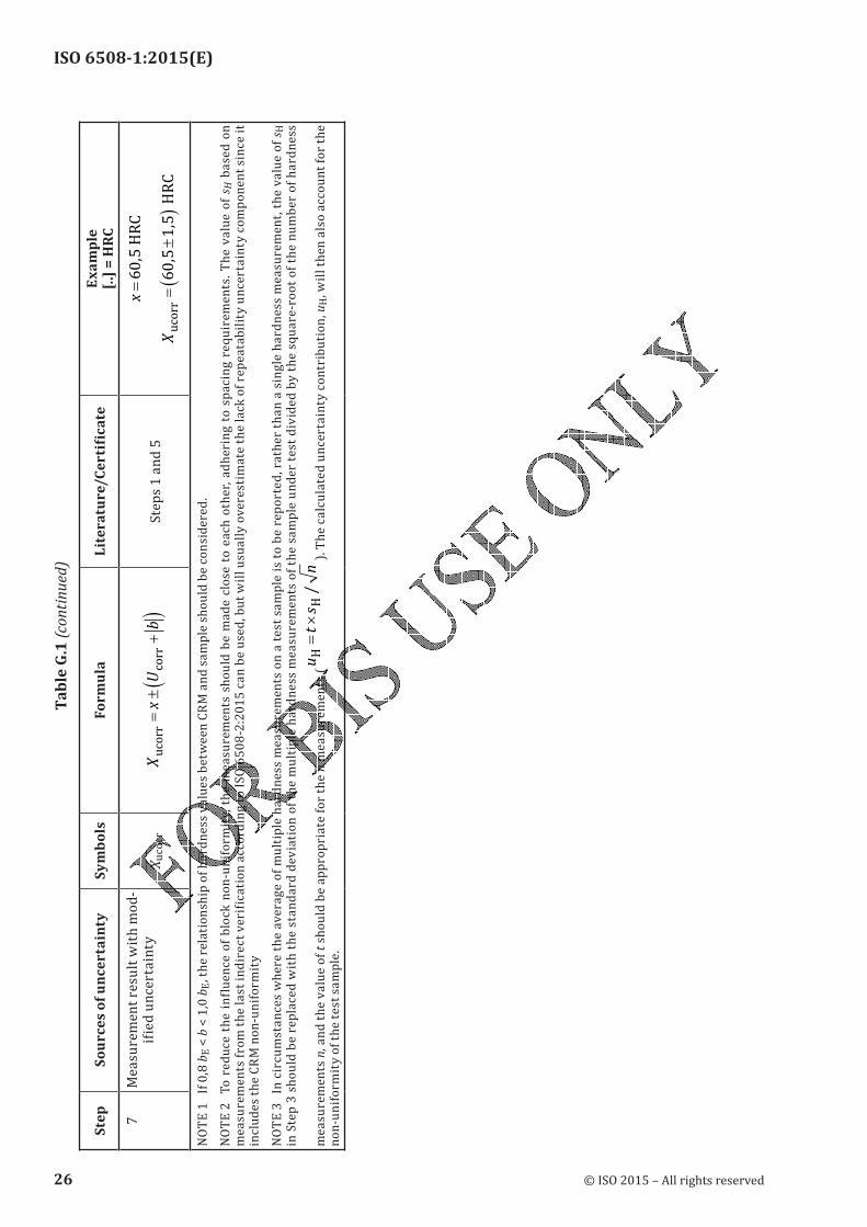
uHCRM is the contribution to the measurement uncertainty due to the combination of the lack of measurement repeatability of the hardness testing machine and the hardness non-uni-formity of the CRM, calculated as the standard deviation of the mean of the hardness measurements when measuring the CRM;ums is the contribution to the measurement uncertainty due to the resolution of the hardness testing machine when measuring the CRM.The result of the measurement is given by Formula (G.3) and Formula (G.4), respectively:X x b Ucorr corr= −( )± (G.3)or byX x U bucorr corr= ± +( ) (G.4)depending on whether the bias (error), b, is considered to be part of the mean value or of the uncertainty.When method M1 is used, it can also be appropriate to include additional uncertainty contributions
within the RSS term relating to the value of b employed. This will particularly be the case when— the measured hardness is significantly different from the hardness levels of the blocks used during the machine’s calibration,— the machine’s bias value varies significantly throughout its calibrated range,— the material being measured is different from the material of the hardness reference blocks used during the machine’s calibration, or— the day-to-day performance (reproducibility) of the hardness testing machine varies significantly.The calculations of these additional contributions to the measurement uncertainty are not discussed here. In all circumstances, a robust method for estimating the uncertainty associated with b is required.
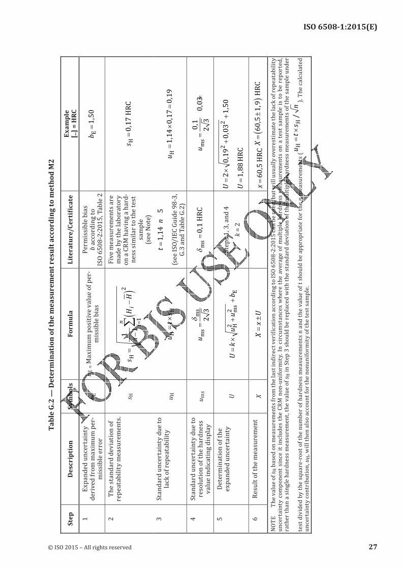
G.4.3 Procedure without bias (method M2)As an alternative to method M1, method M2 can be used in some circumstances. Method M2 is a simplified method which can be used without needing to consider the magnitude of any systematic error of the hardness testing machine; however, Method M2 usually over-estimates the real measurement uncertainty.The procedure for the determination of U is explained in Table G.2.Method M2 is only valid for hardness testing machines that have passed an indirect verification in accordance with ISO 6508-2:2015 using the value ∆ = +H b U
HTMmax HTM, rather than only the bias value, b, when determining compliance with the maximum permissible deviation of the bias (see
ISO 6508-2:2015).In method M2, the bias (error) limit (the positive amount by which the machine’s reading is allowed to differ from the reference block’s value, as specified in ISO 6508-2:2015 is used to define one component bE of the uncertainty. There is no correction of the hardness values with respect to the bias limit.
22 © ISO 2015 – All rights reserved
ISO 6508-1:2015(E)
The combined expanded measurement uncertainty for a single future hardness measurement is calculated as:
U k u u b= × + +H ms E
2 2 (G.5)
where
uH is a contribution to the measurement uncertainty due to the lack of measurement repeatabil-ity of the hardness testing machine;ums is a contribution to the measurement uncertainty due to the resolution of the hardness testing
machine;
bE is the maximum permissible deviation of the bias as specified in ISO 6508-2:2015, and the result of the measurement is given byX x U= ± . (G.6)
G.5 Expression of the result of measurementWhen reporting the measurement result, the method (M1 or M2) used to estimate the uncertainty should also be specified.EXAMPLE A hardness testing machine makes a single Rockwell C hardness measurement, x, on a test sample. Single hardness measurement value, x: x = 60,5 HRC Resolution of the hardness testing machine, δms : δms = 0,1 HRCThe last indirect verification of the testing machine determined a measurement bias, b, with an uncertainty of the bias UHTM using a CRM of x CRM HRC= 62 82, . The hardness of this CRM was the closest to the test sample hardness of those CRMs used for the indirect verification. Testing machine measurement bias, b: b = −0,72 HRC Uncertainty of the testing machine measurement bias, UHTM: UHTM = 0,66 HRCTo determine the lack of repeatability of the testing machine, the laboratory made five HRC measurements Hi on a CRM having a similar hardness to the test sample. The five measurements were made adjacent to each other adhering to spacing requirements in order to reduce the influence of block non-uniformity. Five measurement values, Hi: 61,7 HRC; 61,9 HRC; 62,0 HRC; 62,1 HRC; 62,1 HRC Mean measurement value, H : H =61 69, HRC Standard deviation of the measurement values, sH : s
H HRC=0 17,
where
H
H
n
ii
n
= =∑ 1 (G.7)
and
sn
H Hi
i
n
H=
−
−( )=
∑1
1
2
1
(G.8)
© ISO 2015 – All rights reserved 23
ISO 6508-1:2015(E)
where n = 5.
The value of sH based on measurements from the last indirect verification according to ISO 6508-2:2015 may be used instead of conducting the above repeatability tests; however, this standard deviation value will usually overestimate the lack of repeatability uncertainty component since it also includes the CRM non-uniformity.
24 © ISO 2015 – All rights reserved
ISO 6508-1:2015(E)
Ta
ble
G.1
— D
ete
rm
ina
tio
n o
f th
e m
ea
su
re
me
nt
re
su
lt a
cc
or
din
g t
o m
eth
od
M1
Ste
pS
ou
rc
es
of
un
ce
rta
inty
Sy
mb
ols
Fo
rm
ula
Lite
ratu
re/C
erti
fica
teE
xa
mp
le
[..]
= H
RC
1Bias va
lue b and unce
rtainty
UHTM o
f th
e b
ias
of
the
ha
rd-
ne
ss t
est
ing
ma
chin
e f
rom
th
e
indirect verifi
cationb
UHTM
uHTM
uU
HTM
HTM
=2
b a
nd
UHTM
acc
ord
ing
to
in
dir
ec
t verific
ation report u
sing a CRM
of xCRM
HRC
=6282
,
(se
e N
ote
1)
b = −0,72 HRC
UHTM = 0
,66 HRC
uHTM
HRC
0,33 HRC
==
066
2,
2T
he
sta
nd
ard
de
via
tio
n o
f repeat
ability measu
rements
s Hs
nH
Hi
i
n
H=
−
−(
)=∑
1
1
2
1
Fiv
e m
ea
sure
me
nts
are
made b
y the laborato
ry on a CR
M having a ha
rd-n
ess
sim
ila
r to
th
e t
est
sa
mp
le
(se
e N
ote
2)
s H HRC
=017
,
3Standa
rd uncertainty
due to
lack of repeat
abilityu
Hu
ts
HH
=×
, see NOTE 3
t = 1,14 for n =
5
(see ISO/IEC
Guide 98-3,
G.3
an
d T
ab
le G
.2)
uH
HRC
HRC
=×
()
=114017
019
,,
,
4Standa
rd uncertainty
due to
reso
luti
on
of
the
ha
rdn
ess
value i
ndicating disp
layu
ms
ums
ms
=δ 23
δ ms = 0,1
HRCums=
=01
23
003
,,
5D
ete
rmin
ati
on
of
the
co
r-rected
expanded un
certainty
Uco
rrU
ku
uu
corr
Hms
HTM
=×
++
22
2Steps 1
, 3, and 4
k =
2
Ucorr=
×+
+2
019
003
033
22
2,
,,
Ucorr
HRC
=076
,
6Measu
rement result
with mod-
ified hardness
Xco
rrX
xb
Ucorr
corr
=−
()±
Ste
ps
1 a
nd
5x=605, HRC
Xcorr
HRC
=±
()
612
08
,,
NOTE 1 If 0,8
b E < b < 1,0 b
E, the re
lationship of h
ardness value
s between CR
M and sample
should be con
sidered.
NOTE 2 To re
duce the influ
ence of block
non-uniform
ity, the measu
rements shou
ld be made clo
se to each oth
er, adhering t
o spacing req
uirements. Th
e value of s H b
ase
d o
n
measuremen
ts from the las
t indirect veri
fication accord
ing to ISO 650
8-2:2015 can b
e used, but w
ill usually ove
restimate the
lack of repeat
ability uncert
ainty compon
ent since it
includes the C
RM non-unifor
mityNOTE 3
In circumsta
nces where th
e average of m
ultiple hardn
ess measurem
ents on a test
sample is to b
e reported, ra
ther than a si
ngle hardness
measuremen
t, the value of
s H in Step
3 should be r
eplaced with
the standard
deviation of t
he multiple h
ardness meas
urements of t
he sample und
er test divide
d by the squa
re-root of the
number of h
ardness
me
asu
rem
en
ts n
, an
d t
he
va
lue
of
t sh
ou
ld b
e a
pp
rop
ria
te f
or
the
n m
ea
sure
me
nts
(u
ts
nH
H=
×/
). The calculat
ed uncertaint
y contribution
, u H, will then
also account f
or the non-un
iformity of the
test sample.
© ISO 2015 – All rights reserved 25
ISO 6508-1:2015(E)
Ste
pS
ou
rc
es
of
un
ce
rta
inty
Sy
mb
ols
Fo
rm
ula
Lite
ratu
re/C
erti
fica
teE
xa
mp
le
[..]
= H
RC
7Measu
rement result
with mod-
ified uncertain
tyX
uco
rrX
xU
bucorr
corr
=±
+(
)S
tep
s 1
an
d 5
x=605, HRC
Xucorr
HRC
=±
()
605
15
,,
NOTE 1 If 0,8
b E < b < 1,0 b
E, the re
lationship of h
ardness value
s between CR
M and sample
should be con
sidered.
NOTE 2 To re
duce the influ
ence of block
non-uniform
ity, the measu
rements shou
ld be made clo
se to each oth
er, adhering t
o spacing req
uirements. Th
e value of s H b
ase
d o
n
measuremen
ts from the las
t indirect veri
fication accord
ing to ISO 650
8-2:2015 can b
e used, but w
ill usually ove
restimate the
lack of repeat
ability uncert
ainty compon
ent since it
includes the C
RM non-unifor
mityNOTE 3
In circumsta
nces where th
e average of m
ultiple hardn
ess measurem
ents on a test
sample is to b
e reported, ra
ther than a si
ngle hardness
measuremen
t, the value of
s H in Step
3 should be r
eplaced with
the standard
deviation of t
he multiple h
ardness meas
urements of t
he sample und
er test divide
d by the squa
re-root of the
number of h
ardness
me
asu
rem
en
ts n
, an
d t
he
va
lue
of
t sh
ou
ld b
e a
pp
rop
ria
te f
or
the
n m
ea
sure
me
nts
(u
ts
nH
H=
×/
). The calculat
ed uncertaint
y contribution
, u H, will then
also account f
or the non-un
iformity of the
test sample.
Ta
ble
G.1
(co
nti
nu
ed)
26 © ISO 2015 – All rights reserved
ISO 6508-1:2015(E)
Ta
ble
G.2
— D
ete
rm
ina
tio
n o
f th
e m
ea
su
re
me
nt
re
su
lt a
cc
or
din
g t
o m
eth
od
M2
Ste
pD
es
cr
ipti
on
Sy
mb
ols
Fo
rm
ula
Lite
ratu
re/C
erti
fica
teE
xa
mp
le
[..]
= H
RC
1Expand
ed uncertaint
y d
eri
ve
d f
rom
ma
xim
um
pe
r-m
issi
ble
err
or
b Eb E
= Maxim
um positive va
lue of per-
mis
sib
le b
ias
Pe
rmis
sib
le b
ias
b a
cco
rdin
g t
o
ISO 6508-2:20
15, Table 2
b E=150
,
2T
he
sta
nd
ard
de
via
tio
n o
f repeat
ability measu
rements.
s Hs
nH
Hi
i
n
H=
−
−(
)=∑
1
1
2
1
Fiv
e m
ea
sure
me
nts
are
made b
y the laborato
ry on a CR
M having a ha
rd-n
ess
sim
ila
r to
th
e t
est
sa
mp
le
(se
e N
ote
)
s H HRC
=017
,
3Standa
rd uncertainty
due to
lack of repeat
abilityu
Hu
ts
HH
=×
tn
==
114
5,
(see ISO/IEC
Guide 98-3,
G.3
an
d T
ab
le G
.2)
uH=
×=
114017
019
,,
,
4Standa
rd uncertainty
due to
reso
luti
on
of
the
ha
rdn
ess
value i
ndicating disp
layu
ms
ums
ms
=δ 23
δms
HRC
=01,
ums=
=01
23
003
,,
5D
ete
rmin
ati
on
of
the
expand
ed uncertaint
yU
Uk
uu
b=
×+
+H
ms
E
22
Steps 1, 3, and
4k
= 2
U=
×+
+2
019
003
150
22
,,
,
U=188
, HRC
6R
esu
lt o
f th
e m
ea
sure
me
nt
XX
xU
=±
x=605, HRC
X=
±(
)605
19
,, HRC
NO
TE
T
he
va
lue
of
s H based
on measureme
nts from the l
ast indirect ve
rification acco
rding to ISO 6
508-2:2015 c
an be used, bu
t will usually
overestimate
the lack of rep
eatability
uncertainty c
omponent sin
ce it includes
the CRM non-
uniformity. In
circumstance
s where the a
verage of mu
ltiple hardnes
s measureme
nts on a test
sample is to b
e reported,
rather than a
single hardne
ss measureme
nt, the value
of s H in S
tep
3 s
ho
uld
be
re
pla
ced
wit
h t
he
sta
nd
ard
de
via
tio
n o
f th
e m
ult
iple
ha
rdn
ess
me
asu
rem
en
ts o
f th
e s
am
ple
un
de
r
test divided by
the square-r
oot of the num
ber of hardne
ss measureme
nts n and the
value of t sho
uld be approp
riate for the n
me
asu
rem
en
ts (u
ts
nH
H=
×/
). T
he
ca
lcu
late
d
uncertainty c
ontribution, u H
, will then also
account for th
e nonuniform
ity of the test
sample.
© ISO 2015 – All rights reserved 27
ISO 6508-1:2015(E)
28 © ISO 2015 – All rights reserved
ISO 6508-1:2015(E)
Annex H (informative)
CCM - Working Group on Hardness
In 1999, at the 88th Session of the International Committee of Weights and Measures (CIPM), Dr Kozo Iizuka, President of the Consultative Committee for Mass and Related Quantities (CCM), stated “Although the definition of hardness scales is certainly conventional in the sense of the use of arbitrarily chosen formula, the testing method is defined by a combination of physical quantities expressed by SI units; the standard of hardness is established and maintained in most of NMIs and the traceability to the standard of NMIs is demanded in industry and elsewhere.” The subsequent discussions led to the realization that hardness standards should be included in the key comparison database (KCDB) for the Mutual Recognition Arrangement (MRA), and thus, a full Working Group on Hardness (CCM-WGH) was established in the framework of the CCM.[8]The establishment of the CCM-WGH provided a technical-diplomatic framework in which hardness influenced parameters can be examined, and improved international definitions of the hardness tests can be proposed and approved for NMI use to reduce the measurement differences at the highest national level. Due to the necessity of international agreement, the CCM-WGH has a close liaison with ISO/TC 164/SC 3 in order to ensure proper dissemination of the hardness scales. The most significant improvement of the CCM-WGH definitions is that the parameters of the hardness test are defined with specific values, rather than ranges of acceptable limits as specified by this test method. As applicable, this test method has adopted the defined values of the CCM–WGH definitions as the values to use.The CCM-WGH definitions are published at http://www.bipm.org/
© ISO 2015 – All rights reserved 29
ISO 6508-1:2015(E)
Annex I (informative)
Rockwell Hardness Measurement Traceability
I.1 Traceability definitionThe path to traceability for a Rockwell hardness measurement is different compared to many other measurement quantities, such as length or temperature. This is primarily because hardness measurement, including Rockwell, is made following a defined test procedure using a testing machine that makes multiple measurements of different parameters (e.g. force, depth, time) during the test. Each of these measurements, as well as other test parameters, influences the hardness result.The International Vocabulary of Metrology (VIM3)[10] defines metrological traceability as the property of a measurement result whereby the result can be related to a reference through a documented unbroken chain of calibrations, each contributing to the measurement uncertainty.From this definition, two things are necessary for a measurement result to have traceability:a) an unbroken chain of calibrations, each contributing to the measurement uncertainty;b) a reference to which traceability is claimed.These will define the metrological traceability chain.I.2 Chains of calibrationsISO 6508-2:2015 specifies a set of calibration and verification procedures required to demonstrate that the testing machine is suitable for use in accordance with this part of ISO 6508. The calibration procedures include direct measurements of various components affecting the machine’s performance, such as the test forces, indenter shape, and depth measuring equipment, as well as hardness measurements of a range of reference blocks. Each of these calibration measurements has specified limits within which the result should lie in order for the machine to pass its verification. Historically, the calibration and verification of the machine components has been termed the machine’s Direct Verification and the calibration and verification of the testing machine by reference block measurements is Indirect Verification.ISO 6508-3:2015 specifies both the procedure required to calibrate the reference blocks used in the Indirect Verification of the testing machine and also the required calibration and verification procedures of the machine used to calibrate these blocks.When considering an “unbroken chain of calibrations” to provide measurement traceability to the testing machine, it is apparent that this could come via either the Direct Verification or Indirect Verification path.
Direct Verification requirements specify measurements of individual components of the testing machine, with traceability of each of these measurements being achieved through calibration chains to the International System of units (SI), usually as realized by a National Metrology Institute (NMI). These calibration chains are illustrated on the right-hand side of Figure I.1. Together, these calibration chains form a traceability path for a testing machine.
30 © ISO 2015 – All rights reserved
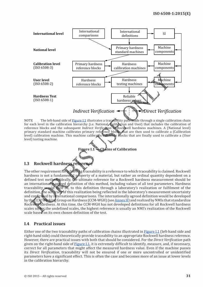
ISO 6508-1:2015(E)
User level
(ISO 6508-2)
Calibration level
(ISO 6508-3)
National level
International level
Reliablehardness values
Machinecomponents
Hardnessreference blocks
Hardnesstesting machines
Primary hardnessreference blocks
Machinecomponents
Hardnesscalibration machines
Machinecomponents
Primary hardnessstandard machines
Internationaldeinitions
Internationalcomparisons
SI
Hardness Test
(ISO 6508-1)
NOTE The left-hand side of Figure I.1 illustrates a traceability path made through a single calibration chain for each level in the calibration hierarchy (i.e. National, Calibration and User) that includes the calibration of reference blocks and the subsequent Indirect Verification of Rockwell hardness machines. A (National level) primary standard machine calibrates primary reference blocks that are then used to calibrate a (Calibration level) calibration machine. This machine calibrates reference blocks that are finally used to calibrate a (User level) testing machine.
Figure I.1 — Chains of Calibration
I.3 Rockwell hardness referenceThe other requirement for achieving traceability is a reference to which traceability is claimed. Rockwell hardness is not a fundamental property of a material, but rather an ordinal quantity dependent on a defined test method. Ideally, the ultimate reference for a Rockwell hardness measurement should be an internationally agreed definition of this method, including values of all test parameters. Hardness traceability would then be, to this definition through a laboratory’s realization or fulfilment of the definition, the accuracy of this realization being reflected in the laboratory’s measurement uncertainty and confirmed by international comparisons. The internationally agreed definition would be developed by the CCM Working Group on Hardness (CCM-WGH) (see Annex H) and realized by NMIs that standardize Rockwell hardness. At this time, the CCM-WGH has not developed definitions for all Rockwell hardness scales so, for the undefined scales, the highest reference is usually an NMI’s realization of the Rockwell scale based on its own chosen definition of the test.I.4 Practical issuesEither one of the two traceability paths of calibration chains illustrated in Figure I.1 (left-hand side and right-hand side) could theoretically provide traceability to an appropriate Rockwell hardness reference. However, there are practical issues with both that should be considered. For the Direct Verification path given on the right-hand side of Figure I.1, it is extremely difficult to identify, measure, and, if necessary, correct for all parameters that might affect the measured hardness value. Even if the machine passes its Direct Verification, traceability will not be ensured if one or more uncontrolled or unidentified parameters have a significant effect. This is often the case and becomes more of an issue at lower levels in the calibration hierarchy.
© ISO 2015 – All rights reserved 31

ISO 6508-1:2015(E)
The Indirect Verification calibration chain shown on the left-hand side of Figure I.1 also has practical issues to be considered. One consequence of using a testing machine having multiple components, each making measurements during the hardness test, is that an error in one component’s measurement can be compensated or offset by an error in a different component’s measurement. This can result in accurate hardness measurements for the specific hardness levels and block materials tested during the indirect verification; however, measurement error can increase when testing other hardness levels or materials. If the errors in the individual machine components are significant, then traceability may not be ensured again.
I.5 Rockwell hardness measurement traceability
I.5.1 GeneralThe above issues indicate that both types of traceability path usually need to be in place for achieving Rockwell hardness measurement traceability. This does not mean that traceability cannot be achieved based on only one of the two paths, if careful examination and evaluation of the measurement process is made. For example, at the National Level, the traceability of an NMI’s primary Rockwell hardness standard machine is achieved through a Direct Verification calibration chain since there is no recognized higher-level hardness reference artefact. Traceability through this path is possible since NMIs typically have the capability to thoroughly evaluate their measurement systems, and their uncertainty levels are confirmed through international comparisons with other NMIs. In contrast, decades of Rockwell hardness measurement experience has shown that, for the lower levels in the calibration hierarchy, it is most practical to obtain traceability and determine measurement uncertainty based primarily on the Indirect Verification calibration chain; however, proper traceability of the individual machine component quantity values is also important. This traceability scheme has proven to be suitable for industrial Rockwell hardness measurements.
I.5.2 Calibration level traceabilityMeasurement traceability is best obtained through the Indirect Verification calibration chain using primary reference blocks that have been calibrated at the National level (NMI). This is also the path that should be used for the determination of measurement uncertainty. At the same time, however, the specified components of the calibration machine should be calibrated on a frequent basis to ensure that offsetting errors are not significant. Hardness traceability should be to the NMI’s realization of the CCM-WGH definition of the Rockwell scale or, when there is an absence of a CCM-WGH definition; traceability should be to the NMI’s realization of its own chosen definition. If the NMI does not provide calibrated reference blocks or conduct comparison measurements with a Calibration laboratory and it is not practical to use reference blocks of another NMI, then the reference to which traceability is claimed might need to be to the Calibration laboratory’s realization of the Rockwell scale definition based on an international test method, such as that defined by the ISO 6508- series. In this case, the Calibration laboratory’s measurement traceability can be achieved through the Indirect Verification path using consensus reference block standards, or through the Direct Verification path confirmed by intercomparisons.
I.5.3 User level traceabilityMeasurement traceability is best obtained through the Indirect Verification calibration chain using reference blocks that have been calibrated at the Calibration level or National level. As with Calibration level traceability, this is the most practical path and should also be used for the determination of measurement uncertainty. It is also desirable that the components of the hardness machine periodically undergo Direct Verification to ensure that offsetting errors are not significant. However, typical industrial practice is for these measurements to be made only when the hardness machine is manufactured or repaired, which is the minimum requirement of the ISO 6508- series.NOTE The following terms used in this Annex are in accordance with the VIM3[10]: calibration, calibration hierarchy, metrological traceability, metrological traceability chain, ordinal quantity and verification.
32 © ISO 2015 – All rights reserved
ISO 6508-1:2015(E)
Bibliography
[1] ISO 3738-1, Hardmetals — Rockwell hardness test (scale A) — Part 1: Test method[2] ISO 4498, Sintered metal materials, excluding hardmetals — Determination of apparent hardness and microhardness[3] ISO/IEC Guide 98-3, Uncertainty of measurement — Part 3: Guide to the expression of uncertainty in measurement (GUM:1995)
[4] Guide Euromet CG-16, Guidelines on the Estimation of Uncertainty in Hardness Measurements, 2007 [http://www.euramet.org]
[5] Gabauer W. Manual of Codes of Practice for the Determination of Uncertainties in Mechanical Tests on Metallic Materials, The Estimation of Uncertainties in Hardness Measurements, Project, No. SMT4-CT97-2165, UNCERT COP 14: 2000[6] Gabauer W., & Binder O. Abschätzung der Messunsicherheit in der Härteprüfung unter Verwendung der indirekten Kalibriermethode, DVM Werkstoffprüfung. Tagungsband, 2000, pp. 255–61.
[7] Polzin T., & Schwenk D. Method for uncertainty determination of hardness testing; PC file for the determination, Materialprüfung, 44 (2002) 3, pp. 64–71[8] Iizuka K. Worldwide Activities Around Hardness Measurement - Activities in CCM/CIPM, IMEKO/TC5, OIML/TC10 and ISO/TC164 in Proceedings HARDMEKO 2007, Tsukuba, Japan, 2007, 1-4[9] Seton Bennett and Joaquin Valdés, 2010 Metrologia 47, number 2, Materials metrology, doi:[10] VIM. International vocabulary of metrology — Basic and general concepts and associated terms, VIM, 3rd edition, JCGM 200: 2008 available via http://www.bipm.org/en/
publications/guides/vim.html
© ISO 2015 – All rights reserved 33
ISO 6508-1:2015(E)
© ISO 2015 – All rights reserved
ICS 77.040.10Price based on 33 pages
© ISO 2015
Metallic materials — Rockwell hardness test —
Part 2: Verification and calibration of testing machines and indenters
Matériaux métalliques — Essai de dureté Rockwell —
Partie 2: Vérification et étalonnage des machines d’essai et des pénétrateurs
INTERNATIONAL STANDARD
ISO6508-2
Third edition2015-03-01
Reference numberISO 6508-2:2015(E)

ISO 6508-2:2015(E)
ii © ISO 2015 – All rights reserved
COPYRIGHT PROTECTED DOCUMENT
© ISO 2015All rights reserved. Unless otherwise specified, no part of this publication may be reproduced or utilized otherwise in any form or by any means, electronic or mechanical, including photocopying, or posting on the internet or an intranet, without prior written permission. Permission can be requested from either ISO at the address below or ISO’s member body in the country of the requester.ISO copyright office
Case postale 56 • CH-1211 Geneva 20Tel. + 41 22 749 01 11Fax + 41 22 749 09 47E-mail [email protected] www.iso.orgPublished in Switzerland
ISO 6508-2:2015(E)
Foreword ........................................................................................................................................................................................................................................iv
1 Scope ................................................................................................................................................................................................................................. 1
2 Normative references ...................................................................................................................................................................................... 1
3 General conditions ............................................................................................................................................................................................. 1
4 Direct verification of the testing machine .................................................................................................................................. 24.1 General ........................................................................................................................................................................................................... 24.2 Calibration and verification of the test force................................................................................................................. 24.3 Calibration and verification of the depth-measuring system ......................................................................... 24.4 Calibration and verification of the testing cycle ......................................................................................................... 34.5 Calibration and verification of the machine hysteresis........................................................................................ 3
5 Indirect verification of the testing machine ............................................................................................................................. 45.1 General ........................................................................................................................................................................................................... 45.2 Procedure .................................................................................................................................................................................................... 45.3 Repeatability ............................................................................................................................................................................................. 55.4 Bias .................................................................................................................................................................................................................... 65.5 Uncertainty of measurement ...................................................................................................................................................... 7
6 Calibration and verification of Rockwell hardness indenters ............................................................................... 76.1 General ........................................................................................................................................................................................................... 76.2 Diamond indenter ................................................................................................................................................................................ 7
6.2.1 General...................................................................................................................................................................................... 76.2.2 Direct calibration and verification of the diamond indenter ..................................................... 76.2.3 Indirect verification of diamond indenters ............................................................................................... 86.3 Ball indenter .............................................................................................................................................................................................. 96.3.1 Direct calibration and verification of the ball indenter .................................................................. 96.3.2 Indirect verification of the ball holder assembly ..............................................................................116.4 Marking ...................................................................................................................................................................................................... 11
7 Intervals between direct and indirect calibrations and verifications .......................................................11
8 Verification report ...........................................................................................................................................................................................12
Annex A (normative) Repeatability of testing machines ..............................................................................................................13
Annex B (informative) Uncertainty of measurement of the calibration results of the hardness testing machine ........................................................................................................................................................................15
Bibliography .............................................................................................................................................................................................................................24
© ISO 2015 – All rights reserved iii
Contents Page
ISO 6508-2:2015(E)
ForewordISO (the International Organization for Standardization) is a worldwide federation of national standards bodies (ISO member bodies). The work of preparing International Standards is normally carried out through ISO technical committees. Each member body interested in a subject for which a technical committee has been established has the right to be represented on that committee. International organizations, governmental and non-governmental, in liaison with ISO, also take part in the work. ISO collaborates closely with the International Electrotechnical Commission (IEC) on all matters of electrotechnical standardization.The procedures used to develop this document and those intended for its further maintenance are described in the ISO/IEC Directives, Part 1. In particular the different approval criteria needed for the different types of ISO documents should be noted. This document was drafted in accordance with the editorial rules of the ISO/IEC Directives, Part 2 (see www.iso.org/directives).Attention is drawn to the possibility that some of the elements of this document may be the subject of patent rights. ISO shall not be held responsible for identifying any or all such patent rights. Details of any patent rights identified during the development of the document will be in the Introduction and/or on the ISO list of patent declarations received (see www.iso.org/patents).Any trade name used in this document is information given for the convenience of users and does not constitute an endorsement.For an explanation on the meaning of ISO specific terms and expressions related to conformity assessment, as well as information about ISO’s adherence to the WTO principles in the Technical Barriers to Trade (TBT) see the following URL: Foreword - Supplementary informationThe committee responsible for this document is ISO ISO/TC 164, Mechanical testing of metals, Subcommittee SC 3, Hardness testing.This third edition cancels and replaces the first edition (ISO 6508-2:2005), which has been technically revised.ISO 6508 consists of the following parts, under the general title Metallic materials — Rockwell hardness test:
— Part 1: Test method
— Part 2: Verification and calibration of testing machines and Indenters
— Part 3: Calibration of reference blocks
iv © ISO 2015 – All rights reserved
Metallic materials — Rockwell hardness test —
Part 2: Verification and calibration of testing machines and indenters
1 ScopeThis part of ISO 6508 specifies two separate methods of verification of testing machines (direct and indirect) for determining Rockwell hardness in accordance with ISO 6508-1:2015, together with a method for verifying Rockwell hardness indenters.The direct verification method is used to determine whether the main parameters associated with the machine function, such as applied force, depth measurement, and testing cycle timing, fall within specified tolerances. The indirect verification method uses a number of calibrated reference hardness blocks to determine how well the machine can measure a material of known hardness.The indirect method may be used on its own for periodic routine checking of the machine in service.If a testing machine is also to be used for other methods of hardness testing, it shall be verified independently for each method.This part of ISO 6508 is applicable to stationary and portable hardness testing machines.Attention is drawn to the fact that the use of tungsten carbide composite for ball indenters is considered to be the standard type of Rockwell indenter ball. Steel indenter balls may continue to be used only when complying with ISO 6508-1:2015, Annex A.2 Normative referencesThe following documents, in whole or in part, are normatively referenced in this document and are indispensable for its application. For dated references, only the edition cited applies. For undated references, the latest edition of the referenced document (including any amendments) applies.ISO 376, Metallic materials — Calibration of force-proving instruments used for the verification of uniaxial testing machinesISO 6507-1, Metallic materials — Vickers hardness test — Part 1: Test methodISO 6508-1:2015, Metallic materials — Rockwell hardness test — Part 1: Test methodISO 6508-3:2015, Metallic materials — Rockwell hardness test — Part 3: Calibration of reference blocks
3 General conditionsBefore a Rockwell hardness testing machine is verified, the machine shall be checked to ensure that it is properly set up and operating in accordance with the manufacturer’s instructions.Especially, it should be checked that the test force can be applied and removed without shock, vibration, or overload and in such a manner that the readings are not influenced.
INTERNATIONAL STANDARD ISO 6508-2:2015(E)
© ISO 2015 – All rights reserved 1
ISO 6508-2:2015(E)
4 Direct verification of the testing machine
4.1 General
4.1.1 Direct verification involves calibration and verification of the following:a) test forces;b) depth-measuring system;c) testing cycle;d) machine hysteresis test.4.1.2 Direct verification should be carried out at a temperature of (23 ± 5) °C. If the verification is made outside of this temperature range, this shall be reported in the verification report.4.1.3 The instruments used for calibration shall be traceable to national standards.
4.1.4 An indirect verification according to Clause 5 shall be performed following a successful direct verification.4.2 Calibration and verification of the test force
4.2.1 Each preliminary test force, F0, (see 4.2.4) and each total test force, F, used (see 4.2.5) shall be measured, and, whenever applicable, this shall be done at not less than three positions of the plunger spaced throughout its range of movement during testing. The preliminary test force shall be held for at least 2 s.
4.2.2 Three readings shall be taken for each force at each position of the plunger. Immediately before each reading is taken, the plunger shall be moved in the same direction as during testing.4.2.3 The forces shall be measured by one of the following two methods:— by means of a force-proving device according to ISO 376 class 1 or better and calibrated for reversibility;— by balancing against a force, accurate to ±0,2 %, applied by means of calibrated masses or by another method having the same accuracy.Evidence should be available to demonstrate that the output of the force-proving device does not vary by more than 0,2 % in the period 1 s to 30 s following a stepped change in force.4.2.4 The tolerance on each measurement of the preliminary test force, F0, (before application and after removal of the additional test force, F1) shall be ±2,0 %, see Formula (B.2) The range of all force measurements (highest value minus lowest value) shall be ≤ 1,5 % of F0.
4.2.5 The tolerance on each measurement of the total test force, F, shall be ±1,0 %. The range of the force measurements (highest value minus lowest value) shall be ≤ 0,75 % of F.
4.3 Calibration and verification of the depth-measuring system
4.3.1 The depth-measuring system shall be calibrated by making known incremental movements of the indenter or the indenter holder.
2 © ISO 2015 – All rights reserved
ISO 6508-2:2015(E)
4.3.2 The instrument or gauge blocks used to verify the depth-measuring system shall have a maximum expanded uncertainty of 0,000 3 mm when calculated with a 95 % confidence level.4.3.3 Calibrate the testing machine’s depth measurement system at not less than four evenly spaced increments covering the full range of the normal working depth measured by the testing machine. For this purpose, the working depth is 0,25 mm for regular Rockwell scales (A, C, D, B, E, F, G, H, K), and 0,1 mm for superficial Rockwell scales (N, T).4.3.4 Some testing machines have a long-stroke depth measuring system where the location of the working range of the depth measuring system varies to suit the sample. This type of testing machine shall be able to electronically verify that the depth measuring device is continuous over the full range. These types of testers shall be verified using the following steps:a) At the approximate top, midpoint, and bottom of the total stroke of the measuring device, verify the depth measurement system at no less than four evenly spaced increments of approximately 0,05 mm at each of the three locations.b) Operate the actuator over its full range of travel to monitor whether the displacement measurement is continuous. The displacement indication shall be continuously indicated over the full range.4.3.5 The depth-measuring system shall correctly indicate within ±0,001 mm for the scales A to K and within ±0,000 5 mm for scales N and T, i.e. within ±0,5 of a scale unit, over each range.4.4 Calibration and verification of the testing cycle
4.4.1 The testing cycle is to be calibrated by the testing machine manufacturer at the time of manufacture and when the testing machine undergoes repair which may have affected the testing cycle. Calibration of the complete testing cycle is not required as part of the direct verification at other times, see Table 10.
4.4.2 The testing cycle shall conform to the testing cycle defined in ISO 6508-1:2015.4.4.3 For testing machines that automatically control the testing cycle, the measurement uncertainty (k = 2) of the timing instrument used to verify the testing cycle shall not exceed 0,2 s. It is recommended that the measured times for the testing cycle, plus or minus the measurement uncertainty (k = 2) of the calibration measurements, not exceed the timing limits specified in ISO 6508-1:2015.4.4.4 For testing machines that require the user to manually control the testing cycle, the testing machine shall be verified to be capable of achieving the defined testing cycle.4.5 Calibration and verification of the machine hysteresis
4.5.1 The machine shall be checked to ensure that the readings are not affected by a hysteresial flexure of testing machine components (e.g. frame, specimen holder, etc.) during a test. The influence of any hysteresis behaviour shall be checked by making repeated hardness tests using a spherical indenter of at least 10 mm diameter, bearing directly against the specimen holder or through a spacer such that no permanent deformation occurs. A parallel block placed between the indenter holder and the specimen holder may be used instead of a blunt indenter. The material of the blunt indenter and of the spacer or parallel block shall have a hardness of at least 60 HRC.
4.5.2 Perform repeated Rockwell tests using the setup defined in 4.5.1. The tests shall be conducted using the Rockwell scale with the highest test force that is used during normal testing. Repeat the hysteresis verification procedure for a maximum of 10 measurements and average the last three tests.
© ISO 2015 – All rights reserved 3
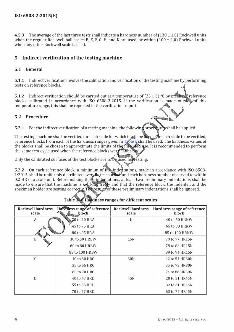
ISO 6508-2:2015(E)
4.5.3 The average of the last three tests shall indicate a hardness number of (130 ± 1,0) Rockwell units when the regular Rockwell ball scales B, E, F, G, H, and K are used, or within (100 ± 1,0) Rockwell units when any other Rockwell scale is used.5 Indirect verification of the testing machine
5.1 General
5.1.1 Indirect verification involves the calibration and verification of the testing machine by performing tests on reference blocks.
5.1.2 Indirect verification should be carried out at a temperature of (23 ± 5) °C by means of reference blocks calibrated in accordance with ISO 6508-3:2015. If the verification is made outside of this temperature range, this shall be reported in the verification report.5.2 Procedure
5.2.1 For the indirect verification of a testing machine, the following procedures shall be applied.The testing machine shall be verified for each scale for which it will be used. For each scale to be verified, reference blocks from each of the hardness ranges given in Table 1 shall be used. The hardness values of the blocks shall be chosen to approximate the limits of the intended use. It is recommended to perform the same test cycle used when the reference blocks were calibrated.Only the calibrated surfaces of the test blocks are to be used for testing.5.2.2 On each reference block, a minimum of five indentations, made in accordance with ISO 6508-1:2015, shall be uniformly distributed over the test surface and each hardness number observed to within 0,2 HR of a scale unit. Before making these indentations, at least two preliminary indentations shall be made to ensure that the machine is working freely and that the reference block, the indenter, and the specimen holder are seating correctly. The results of these preliminary indentations shall be ignored.
Table 1 — Hardness ranges for different scales
Rockwell hardness scale
Hardness range of reference block
Rockwell hardness scale
Hardness range of reference block
A 20 to 40 HRA
45 to 75 HRA
80 to 95 HRA
K 40 to 60 HRKW65 to 80 HRKW85 to 100 HRKWB 10 to 50 HRBW
60 to 80 HRBW
85 to 100 HRBW
15N 70 to 77 HR15N
78 to 88 HR15N
89 to 94 HR15N
C 10 to 30 HRC
35 to 55 HRC
60 to 70 HRC
30N 42 to 54 HR30N
55 to 73 HR30N
74 to 86 HR30N
D 40 to 47 HRD
55 to 63 HRD
70 to 77 HRD
45N 20 to 31 HR45N
32 to 61 HR45N
63 to 77 HR45N
4 © ISO 2015 – All rights reserved
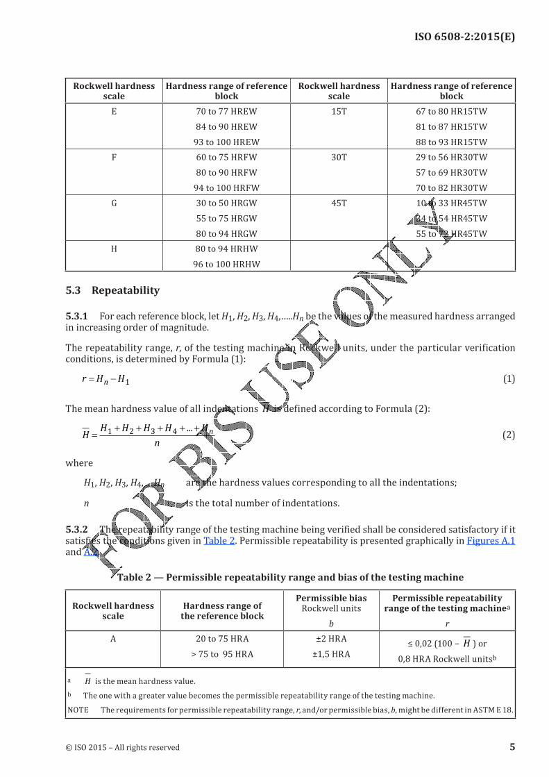
ISO 6508-2:2015(E)
Rockwell hardness scale
Hardness range of reference block
Rockwell hardness scale
Hardness range of reference block
E 70 to 77 HREW
84 to 90 HREW
93 to 100 HREW
15T 67 to 80 HR15TW
81 to 87 HR15TW
88 to 93 HR15TW
F 60 to 75 HRFW
80 to 90 HRFW
94 to 100 HRFW
30T 29 to 56 HR30TW
57 to 69 HR30TW
70 to 82 HR30TW
G 30 to 50 HRGW
55 to 75 HRGW
80 to 94 HRGW
45T 10 to 33 HR45TW
34 to 54 HR45TW
55 to 72 HR45TW
H 80 to 94 HRHW
96 to 100 HRHW
5.3 Repeatability
5.3.1 For each reference block, let H1, H2, H3, H4,…..Hn be the values of the measured hardness arranged in increasing order of magnitude.The repeatability range, r, of the testing machine in Rockwell units, under the particular verification conditions, is determined by Formula (1):
r H Hn
= − 1 (1)
The mean hardness value of all indentations H is defined according to Formula (2):H
H H H H H
n
n=
+ + + + +1 2 3 4 ... (2)
where
H1, H2, H3, H4,…..Hn are the hardness values corresponding to all the indentations;
n is the total number of indentations.
5.3.2 The repeatability range of the testing machine being verified shall be considered satisfactory if it satisfies the conditions given in Table 2. Permissible repeatability is presented graphically in Figures A.1 and A.2.
Table 2 — Permissible repeatability range and bias of the testing machine
Rockwell hardness scale
Hardness range of the reference block
Permissible bias Rockwell units
b
Permissible repeatability range of the testing machinea
r
A 20 to 75 HRA
> 75 to 95 HRA
±2 HRA±1,5 HRA ≤ 0,02 (100 − H ) or0,8 HRA Rockwell unitsb
a H is the mean hardness value.
b The one with a greater value becomes the permissible repeatability range of the testing machine.NOTE The requirements for permissible repeatability range, r, and/or permissible bias, b, might be different in ASTM E 18.
© ISO 2015 – All rights reserved 5
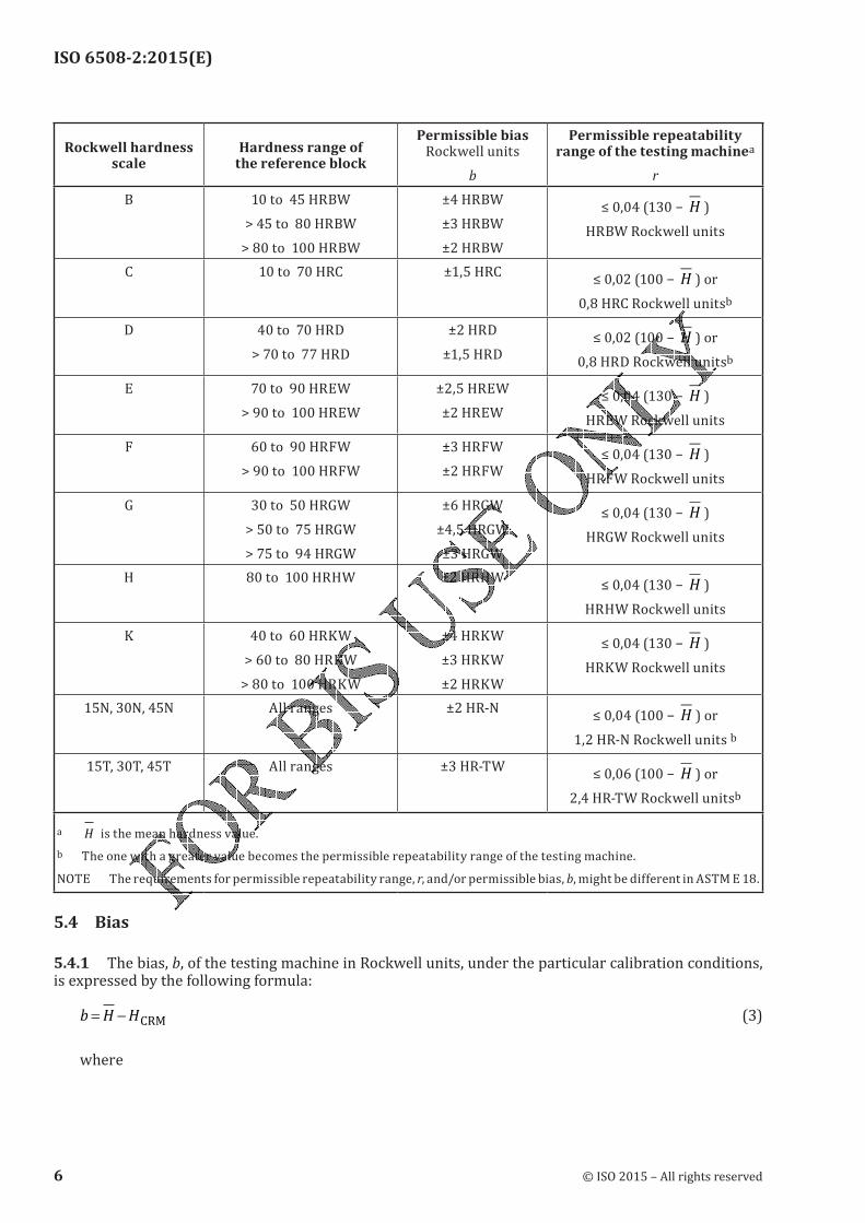
ISO 6508-2:2015(E)
Rockwell hardness scale
Hardness range of the reference block
Permissible bias Rockwell units
b
Permissible repeatability range of the testing machinea
r
B 10 to 45 HRBW
> 45 to 80 HRBW
> 80 to 100 HRBW
±4 HRBW±3 HRBW±2 HRBW≤ 0,04 (130 − H )
HRBW Rockwell units
C 10 to 70 HRC ±1,5 HRC ≤ 0,02 (100 − H ) or0,8 HRC Rockwell unitsb
D 40 to 70 HRD
> 70 to 77 HRD
±2 HRD±1,5 HRD ≤ 0,02 (100 − H ) or0,8 HRD Rockwell unitsb
E 70 to 90 HREW
> 90 to 100 HREW
±2,5 HREW±2 HREW ≤ 0,04 (130 − H )
HREW Rockwell units
F 60 to 90 HRFW
> 90 to 100 HRFW
±3 HRFW±2 HRFW ≤ 0,04 (130 − H )
HRFW Rockwell units
G 30 to 50 HRGW
> 50 to 75 HRGW
> 75 to 94 HRGW
±6 HRGW±4,5 HRGW±3 HRGW≤ 0,04 (130 − H )
HRGW Rockwell units
H 80 to 100 HRHW ±2 HRHW ≤ 0,04 (130 − H )
HRHW Rockwell unitsK 40 to 60 HRKW> 60 to 80 HRKW> 80 to 100 HRKW±4 HRKW±3 HRKW±2 HRKW
≤ 0,04 (130 − H )HRKW Rockwell units15N, 30N, 45N All ranges ±2 HR-N ≤ 0,04 (100 − H ) or1,2 HR-N Rockwell units b15T, 30T, 45T All ranges ±3 HR-TW ≤ 0,06 (100 − H ) or2,4 HR-TW Rockwell unitsb
a H is the mean hardness value.
b The one with a greater value becomes the permissible repeatability range of the testing machine.NOTE The requirements for permissible repeatability range, r, and/or permissible bias, b, might be different in ASTM E 18.5.4 Bias
5.4.1 The bias, b, of the testing machine in Rockwell units, under the particular calibration conditions, is expressed by the following formula:b H H= − CRM (3)
where
6 © ISO 2015 – All rights reserved
ISO 6508-2:2015(E)
H is the mean hardness value, from Formula (2);HCRM is the certified hardness of the reference block used.
5.4.2 The bias of the testing machine shall not exceed the values given in Table 2.
5.5 Uncertainty of measurementA method to determine the uncertainty of measurement of the calibration results of the hardness testing machines is given in Annex B.
6 Calibration and verification of Rockwell hardness indenters
6.1 General
6.1.1 Indenter calibrations and verifications should be carried out at a temperature of (23 ± 5) °C. If the verification is made outside of this temperature range, this shall be reported in the verification report.6.1.2 The instruments used for calibration and verifications shall be traceable to national standards.6.2 Diamond indenter
6.2.1 GeneralTo verify the reliable performance of the spheroconical diamond indenter in conformance with this part of ISO 6508, a direct and an indirect calibration and verification shall be carried out on each indenter.6.2.2 Direct calibration and verification of the diamond indenter
6.2.2.1 The surfaces of the diamond cone and spherical tip shall be polished for a penetration depth of 0,3 mm and shall blend in a smooth tangential manner. Both surfaces shall be free from surface defects.6.2.2.2 The verification of the shape of the indenter can be made by direct measurement or optically. The verification shall be made at not less than four unique equally spaced axial planes (for example, at 0°, 45°, 90°, 135°). Measurement with a collimator device is also acceptable. In this case, the measurements should be carried out at least in four central angles and the central angle of 120° shall be included.The location where the spherical tip and the cone of the diamond blend together will vary depending on the values of the tip radius and cone angle. Ideally for a perfect indenter geometry, the blend point is located at 100 µm from the indenter axis measured along a line normal to the indenter axis. To avoid including the blend area in the measurement of the tip radius and cone angle, the portion of the diamond surface between 80 µm and 120 µm may be ignored.6.2.2.3 The instruments used to verify the shape of the diamond indenter shall have the following maximum expanded uncertainty when calculated with a 95 % confidence level:— angle: 0,1°;— radius: 0,005 mm.6.2.2.4 The diamond cone shall have an included angle of (120 ± 0,35)°.6.2.2.5 The tip of the indenter shall be spherical. Its mean radius shall be determined from at least four single values, measured in the axial section planes defined in 6.2.2.2. Each single value shall be within
© ISO 2015 – All rights reserved 7
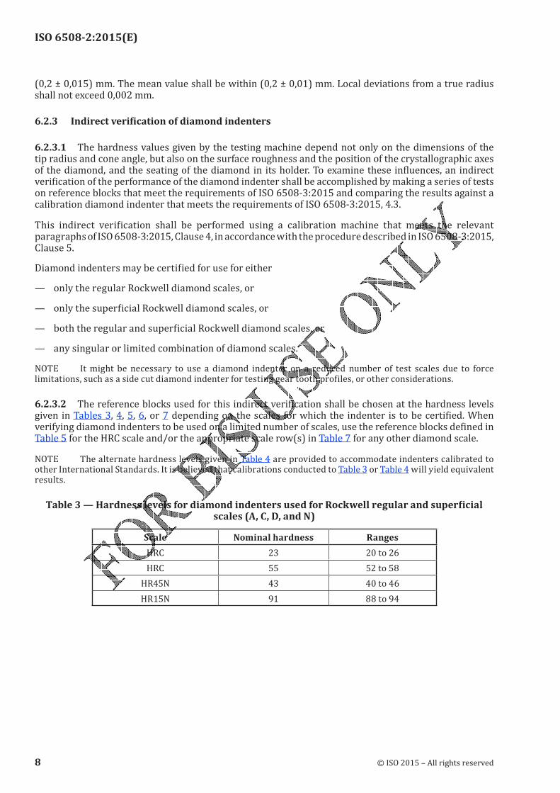
ISO 6508-2:2015(E)
(0,2 ± 0,015) mm. The mean value shall be within (0,2 ± 0,01) mm. Local deviations from a true radius shall not exceed 0,002 mm.6.2.3 Indirect verification of diamond indenters
6.2.3.1 The hardness values given by the testing machine depend not only on the dimensions of the tip radius and cone angle, but also on the surface roughness and the position of the crystallographic axes of the diamond, and the seating of the diamond in its holder. To examine these influences, an indirect verification of the performance of the diamond indenter shall be accomplished by making a series of tests on reference blocks that meet the requirements of ISO 6508-3:2015 and comparing the results against a calibration diamond indenter that meets the requirements of ISO 6508-3:2015, 4.3.This indirect verification shall be performed using a calibration machine that meets the relevant paragraphs of ISO 6508-3:2015, Clause 4, in accordance with the procedure described in ISO 6508-3:2015, Clause 5.Diamond indenters may be certified for use for either— only the regular Rockwell diamond scales, or— only the superficial Rockwell diamond scales, or— both the regular and superficial Rockwell diamond scales, or— any singular or limited combination of diamond scales.NOTE It might be necessary to use a diamond indenter on a reduced number of test scales due to force limitations, such as a side cut diamond indenter for testing gear tooth profiles, or other considerations.6.2.3.2 The reference blocks used for this indirect verification shall be chosen at the hardness levels given in Tables 3, 4, 5, 6, or 7 depending on the scales for which the indenter is to be certified. When verifying diamond indenters to be used on a limited number of scales, use the reference blocks defined in Table 5 for the HRC scale and/or the appropriate scale row(s) in Table 7 for any other diamond scale.NOTE The alternate hardness levels given in Table 4 are provided to accommodate indenters calibrated to other International Standards. It is believed that calibrations conducted to Table 3 or Table 4 will yield equivalent results.
Table 3 — Hardness levels for diamond indenters used for Rockwell regular and superficial scales (A, C, D, and N)
Scale Nominal hardness RangesHRC 23 20 to 26
HRC 55 52 to 58
HR45N 43 40 to 46
HR15N 91 88 to 94
8 © ISO 2015 – All rights reserved
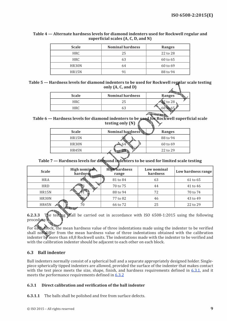
ISO 6508-2:2015(E)
Table 4 — Alternate hardness levels for diamond indenters used for Rockwell regular and superficial scales (A, C, D, and N)
Scale Nominal hardness RangesHRC 25 22 to 28
HRC 63 60 to 65
HR30N 64 60 to 69
HR15N 91 88 to 94
Table 5 — Hardness levels for diamond indenters to be used for Rockwell regular scale testing only (A, C, and D)
Scale Nominal hardness RangesHRC 25 22 to 28
HRC 63 60 to 65
Table 6 — Hardness levels for diamond indenters to be used for Rockwell superficial scale testing only (N)
Scale Nominal hardness RangesHR15N 91 88 to 94
HR30N 64 60 to 69
HR45N 25 22 to 29
Table 7 — Hardness levels for diamond indenters to be used for limited scale testing
ScaleHigh nominal
hardnessHigh hardness
rangeLow nominal
hardnessLow hardness range
HRA 83 81 to 84 63 61 to 65
HRD 73 70 to 75 44 41 to 46
HR15N 91 88 to 94 72 70 to 74
HR30N 80 77 to 82 46 43 to 49
HR45N 70 66 to 72 25 22 to 29
6.2.3.3 The testing shall be carried out in accordance with ISO 6508-1:2015 using the following procedure.For each block, the mean hardness value of three indentations made using the indenter to be verified shall not differ from the mean hardness value of three indentations obtained with the calibration indenter by more than ±0,8 Rockwell units. The indentations made with the indenter to be verified and with the calibration indenter should be adjacent to each other on each block.6.3 Ball indenterBall indenters normally consist of a spherical ball and a separate appropriately designed holder. Single-piece spherically tipped indenters are allowed, provided the surface of the indenter that makes contact with the test piece meets the size, shape, finish, and hardness requirements defined in 6.3.1, and it meets the performance requirements defined in 6.3.2
6.3.1 Direct calibration and verification of the ball indenter
6.3.1.1 The balls shall be polished and free from surface defects.
© ISO 2015 – All rights reserved 9
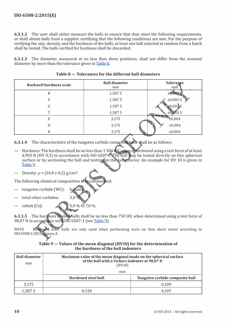
ISO 6508-2:2015(E)
6.3.1.2 The user shall either measure the balls to ensure that they meet the following requirements, or shall obtain balls from a supplier certifying that the following conditions are met. For the purpose of verifying the size, density, and the hardness of the balls, at least one ball selected at random from a batch shall be tested. The balls verified for hardness shall be discarded.6.3.1.3 The diameter, measured at no less than three positions, shall not differ from the nominal diameter by more than the tolerance given in Table 8.
Table 8 — Tolerances for the different ball diameters
Rockwell hardness scaleBall diameter
mmTolerance
mm
B
F
G
T
1,587 51,587 51,587 51,587 5±0,003 5±0,003 5±0,003 5±0,003 5
E
HK3,1753,1753,175
±0,004±0,004±0,0046.3.1.4 The characteristics of the tungsten carbide composite balls shall be as follows:— Hardness: The hardness shall be no less than 1 500 HV, when determined using a test force of at least 4,903 N (HV 0,5) in accordance with ISO 6507-1. The ball may be tested directly on this spherical surface or by sectioning the ball and testing on the ball interior. An example for HV 10 is given in
Table 9.— Density: ρ = (14,8 ± 0,2) g/cm3.
The following chemical composition is recommended:
— tungsten carbide (WC): balance;— total other carbides: 2,0 %;— cobalt (Co): 5,0 % to 7,0 %.6.3.1.5 The hardness of steel balls shall be no less than 750 HV, when determined using a test force of 98,07 N in accordance with ISO 6507-1 (see Table 9).NOTE Hardened steel balls are only used when performing tests on thin sheet metal according to ISO 6508-1:2015, Annex A.
Table 9 — Values of the mean diagonal (HV10) for the determination of the hardness of the ball indenters
Ball diameter
mm
Maximum value of the mean diagonal made on the spherical surface of the ball with a Vickers indenter at 98,07 N
(HV10)
mm
Hardened steel ball Tungsten carbide composite ball3,175 0,1091,587 5 0,150 0,107
10 © ISO 2015 – All rights reserved
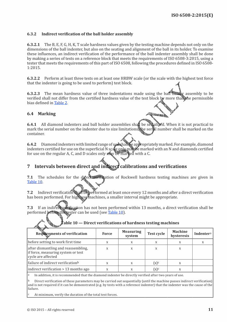
ISO 6508-2:2015(E)
6.3.2 Indirect verification of the ball holder assembly
6.3.2.1 The B, E, F, G, H, K, T scale hardness values given by the testing machine depends not only on the dimensions of the ball indenter, but also on the seating and alignment of the ball in its holder. To examine these influences, an indirect verification of the performance of the ball indenter assembly shall be done by making a series of tests on a reference block that meets the requirements of ISO 6508-3:2015, using a tester that meets the requirements of this part of ISO 6508, following the procedures defined in ISO 6508-1:2015.
6.3.2.2 Perform at least three tests on at least one HRBW scale (or the scale with the highest test force that the indenter is going to be used to perform) test block.
6.3.2.3 The mean hardness value of three indentations made using the ball holder assembly to be verified shall not differ from the certified hardness value of the test block by more than the permissible bias defined in Table 2.
6.4 Marking
6.4.1 All diamond indenters and ball holder assemblies shall be serialized. When it is not practical to mark the serial number on the indenter due to size limitations, the serial number shall be marked on the container.
6.4.2 Diamond indenters with limited range of use shall be appropriately marked. For example, diamond indenters certified for use on the superficial N scale only may be marked with an N and diamonds certified for use on the regular A, C, and D scales only may be marked with a C.7 Intervals between direct and indirect calibrations and verifications
7.1 The schedules for the direct verification of Rockwell hardness testing machines are given in Table 10.
7.2 Indirect verification shall be performed at least once every 12 months and after a direct verification has been performed. For high-use machines, a smaller interval might be appropriate.7.3 If an indirect verification has not been performed within 13 months, a direct verification shall be performed before the tester can be used (see Table 10).
Table 10 — Direct verifications of hardness testing machines
Requirements of verification ForceMeasuring
system Test cycle Machine hysteresis Indenterabefore setting to work first time x x x x xafter dismantling and reassembling, if force, measuring system or test cycle are affected x x x x
failure of indirect verificationb x x (x)c xindirect verification > 13 months ago x x (x)c x
a In addition, it is recommended that the diamond indenter be directly verified after two years of use.b Direct verification of these parameters may be carried out sequentially (until the machine passes indirect verification) and is not required if it can be demonstrated (e.g. by tests with a reference indenter) that the indenter was the cause of the failure.
c At minimum, verify the duration of the total test forces.
© ISO 2015 – All rights reserved 11
ISO 6508-2:2015(E)
8 Verification reportA verification report is required for the direct and indirect verifications of testing machines and indenters. The verification report certificate shall at minimum include the following information:a) a reference to this part of ISO 6508, i.e. ISO 6508-2;b) method of verification (direct and/or indirect);c) identification data for the hardness testing machine, or indenter/ball holder;d) means of verification (reference blocks, elastic proving devices, etc.);e) Rockwell hardness scale(s) verified;f) diamond scale indenter reports shall indicate the scale(s) the indenter is certified to perform;g) verification temperature, if the verification was carried out outside of (23 ± 5) °C;h) result obtained;i) date of verification and reference to the verification institution;j) uncertainty of the verification result. Examples are indicated in Annex B.
12 © ISO 2015 – All rights reserved
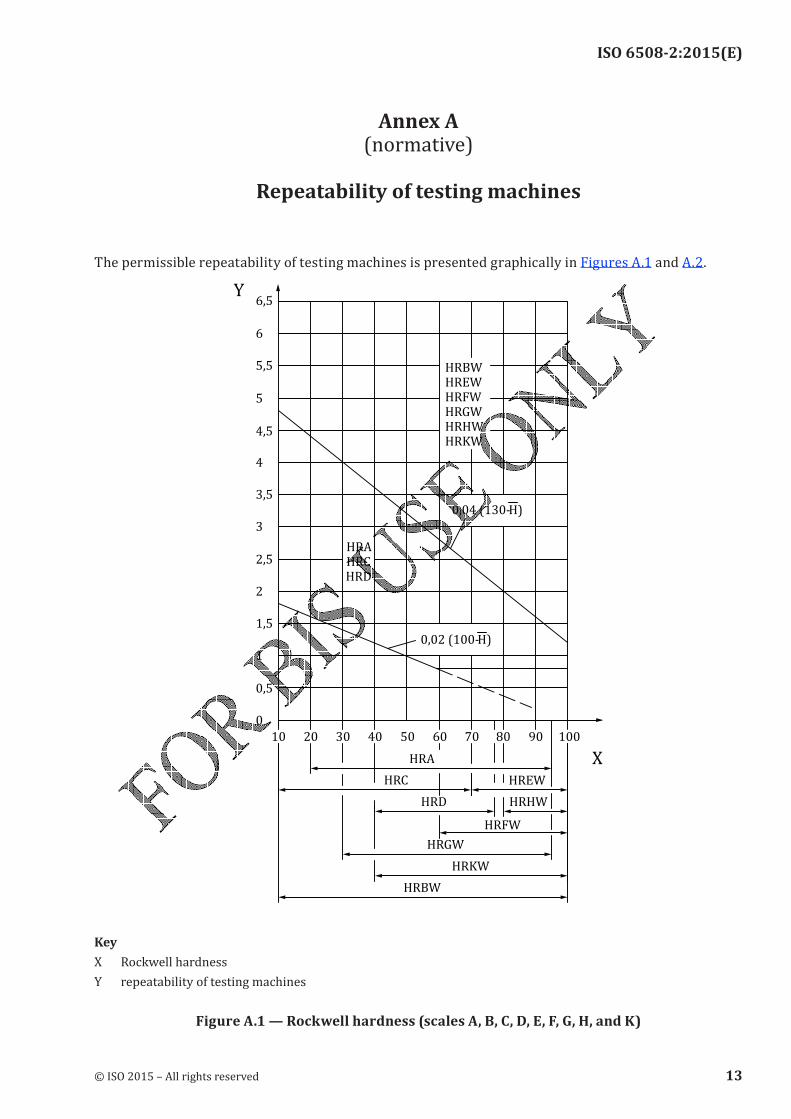
ISO 6508-2:2015(E)
Annex A (normative)
Repeatability of testing machines
The permissible repeatability of testing machines is presented graphically in Figures A.1 and A.2.
6, 5
6
4, 5
5, 5
5
4
3, 5
H R E WH R B W
H R H WH R G WH R F W
H R K W
40
2, 5
3
2
H R A
H R DH R C
1, 5
1
0
0, 5
20 30 50 60 70 80 90 100
Y
X
0, 04 ( 130-H )
0, 02 ( 100-H )
10
H R G W
H R K W
H R F W
H R D
H R E W
H R H W
H R B W
H R C
H R A
KeyX Rockwell hardness
Y repeatability of testing machinesFigure A.1 — Rockwell hardness (scales A, B, C, D, E, F, G, H, and K)
© ISO 2015 – All rights reserved 13
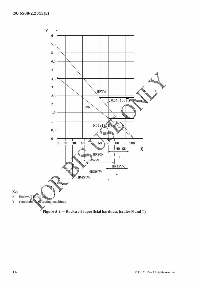
ISO 6508-2:2015(E)
3, 5
4, 5
5, 5
5
4
40
1, 5
2, 5
2
3
1
0, 5
0
2010 30
HRTW
HRN
50 60 70 80 90 100
Y
X
0,04 (100-H)
0,06 (100-H)
6
HR45TW
HR30TW
HR45N
HR15TW
HR30N
HR15N
KeyX Rockwell hardness
Y repeatability of testing machinesFigure A.2 — Rockwell superficial hardness (scales N and T)
14 © ISO 2015 – All rights reserved
ISO 6508-2:2015(E)
Annex B (informative)
Uncertainty of measurement of the calibration results of the
hardness testing machine
B.1 GeneralMeasurement uncertainty analysis is a useful tool to help determine sources of error and to understand differences between measured values. This annex gives guidance on uncertainty estimation, but the methods contained are for information only, unless specifically instructed otherwise by the customer. The criteria specified in this part of ISO 6508 for the performance of the testing machine have been developed and refined over a significant period of time. When determining a specific tolerance that the machine needs to meet, the uncertainty associated with the use of measuring equipment and/or reference standards has been incorporated within this tolerance and it would therefore be inappropriate to make any further allowance for this uncertainty by, for example, reducing the tolerance by the measurement uncertainty. This applies to all measurements made when performing a direct or indirect verification of the machine. In each case, it is simply the measured value resulting from the use of the specified measuring equipment and/or reference standards that is used to assess whether or not the machine complies with this part of ISO 6508. However, there can be special circumstances where reducing the tolerance by the measurement uncertainty is appropriate. This should only be done by agreement of the parties involved.
B.2 Direct verification — Uncertainty of calibration of machine components
B.2.1 Uncertainty of calibration of the test forceFor the direct calibration of force, the difference ΔF between each individual measurement of force applied by the hardness machine and the corresponding force value indicated by the reference instrument is calculated and reported. The direct verification verifies whether each ΔF is within the specified maximum permissible limits. Consequently, the following is a procedure to calculate the uncertainties of the ΔF values with respect to the true value of force specified by the test. The combined relative standard uncertainty of the test force calibration is calculated according to Formula (B.1):u u u uF FRS
2
FHTM ms
2= + +
2 (B.1)
where
uFRS is the relative uncertainty of measurement of the force transducer (from calibration cer-tificate);uFHTM is the relative standard uncertainty of the test force generated by the hardness testing
machine;
ums is the relative uncertainty of measurement due to the resolution of the measuring system.The uncertainty of measurement of the reference instrument, force transducer, is indicated in the corresponding calibration certificate. Influence quantities like the following should be considered for critical applications:
— temperature dependence;
© ISO 2015 – All rights reserved 15
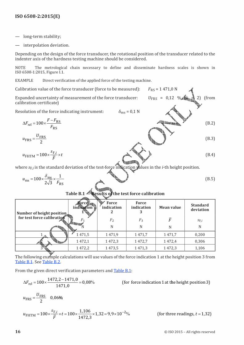
ISO 6508-2:2015(E)
— long-term stability;— interpolation deviation.Depending on the design of the force transducer, the rotational position of the transducer related to the indenter axis of the hardness testing machine should be considered.NOTE The metrological chain necessary to define and disseminate hardness scales is shown in ISO 6508-1:2015, Figure I.1.EXAMPLE Direct verification of the applied force of the testing machine.Calibration value of the force transducer (force to be measured): FRS = 1 471,0 NExpanded uncertainty of measurement of the force transducer: UFRS = 0,12 % (k = 2) (from calibration certificate)Resolution of the force indicating instrument: δms = 0,1 N
∆FF F
Frel
RS
RS
= ×−
100 (B.2)
uU
FRSFRS=2
(B.3)
us
Ft
i
FHTM
F= × ×100
, (B.4)
where sF,i is the standard deviation of the test-force indication values in the i-th height position.
uF
msms
RS
= × ×1002 3
1δ (B.5)
Table B.1 — Results of the test force calibration
Number of height position for test force calibration
Force indication
1
Force indication
2
Force indication
3Mean value Standard
deviation
F1
N
F2
N
F3
N
F
N
sF,i
N
1 1 471,5 1 471,9 1 471,7 1 471,7 0,2002 1 472,1 1 472,3 1 472,7 1 472,4 0,3063 1 472,2 1 473,5 1 471,3 1 472,3 1,106
The following example calculations will use values of the force indication 1 at the height position 3 from Table B.1. See Table B.2.From the given direct verification parameters and Table B.1:
∆ %Frel = ×−
=1001472 2 1471 0
1471 00 08 1
, ,
,, (for force indication at thheheight position3)
uU
FRSFRS= =2
0 06� �
us
Ft
i
FHTM
F= × × = × × = ×
−100 100
1 106
1472 31 32 9 9 10 2, ,
,, , (% for three readings, t =1 32, )
16 © ISO 2015 – All rights reserved
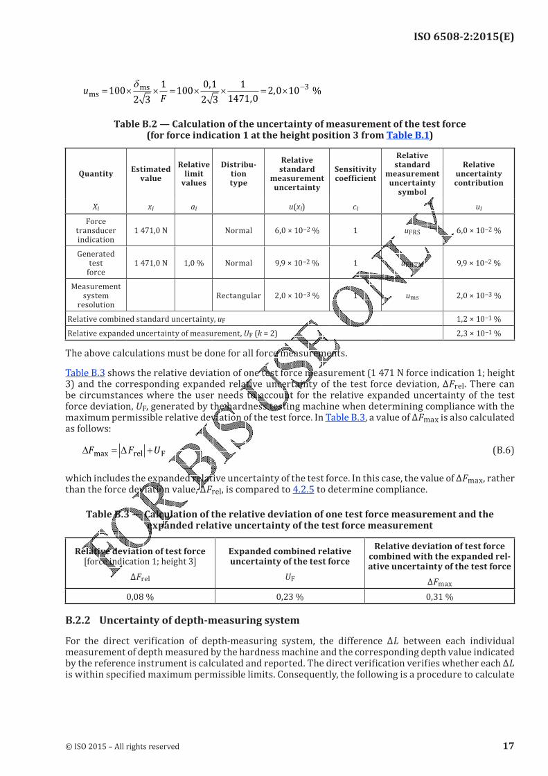
ISO 6508-2:2015(E)
uF
msms %= × × = × × = ×
−100
2 3
1100
0 1
2 3
1
1471 02 0 10
3δ ,
,,
Table B.2 — Calculation of the uncertainty of measurement of the test force (for force indication 1 at the height position 3 from Table B.1)
Quantity Estimated value
Relative limit
values
Distribu-tion type
Relative standard
measurement uncertainty
Sensitivity coefficient
Relative standard
measurement uncertainty
symbol
Relative uncertainty contribution
Xi xi ai u(xi) ci ui
Force transducer indication
1 471,0 N Normal 6,0 × 10⁻² % 1 uFRS 6,0 × 10⁻² %Generated
test force
1 471,0 N 1,0 % Normal 9,9 × 10⁻² % 1 uFHTM 9,9 × 10⁻² %Measurement system
resolutionRectangular 2,0 × 10⁻³ % 1 ums 2,0 × 10⁻³ %
Relative combined standard uncertainty, uF 1,2 × 10⁻¹ %Relative expanded uncertainty of measurement, UF (k = 2) 2,3 × 10⁻¹ %The above calculations must be done for all force measurements.
Table B.3 shows the relative deviation of one test force measurement (1 471 N force indication 1; height 3) and the corresponding expanded relative uncertainty of the test force deviation, ΔFrel. There can be circumstances where the user needs to account for the relative expanded uncertainty of the test force deviation, UF, generated by the hardness testing machine when determining compliance with the maximum permissible relative deviation of the test force. In Table B.3, a value of ΔFmax is also calculated as follows:
∆ ∆F F Umax = +rel F (B.6)which includes the expanded relative uncertainty of the test force. In this case, the value of ΔFmax, rather than the force deviation value, ΔFrel, is compared to 4.2.5 to determine compliance.
Table B.3 — Calculation of the relative deviation of one test force measurement and the expanded relative uncertainty of the test force measurement
Relative deviation of test force [force indication 1; height 3]ΔFrel
Expanded combined relative uncertainty of the test force
UF
Relative deviation of test force combined with the expanded rel-ative uncertainty of the test forceΔFmax0,08 % 0,23 % 0,31 %
B.2.2 Uncertainty of depth-measuring systemFor the direct verification of depth-measuring system, the difference ΔL between each individual measurement of depth measured by the hardness machine and the corresponding depth value indicated by the reference instrument is calculated and reported. The direct verification verifies whether each ΔL is within specified maximum permissible limits. Consequently, the following is a procedure to calculate
© ISO 2015 – All rights reserved 17
ISO 6508-2:2015(E)
the uncertainties of the ΔL values with respect to the true value of the depth. The combined standard uncertainty of the reference instrument for the depth-measuring system is calculated as follows:u u u uL LRS ms LHTM= + +
2 2 2 (B.7)
where
uLRS is the uncertainty of measurement of the depth calibration device (reference standard) from the calibration certificate for k = 1;
ums is the uncertainty of measurement due to the resolution of the measuring system;uLHTM is the standard uncertainty of measurement of the hardness testing machine.The uncertainty of measurement of the reference instrument for the depth-measuring system, the depth calibration device, is indicated in the corresponding calibration certificate. It is assumed that quantities, such as the following, do not exert an essential influence on the uncertainty of measurement of the
depth calibration device:
— temperature dependence;— long-term stability;— interpolation deviation.EXAMPLE Direct verification of the depth measuring system of the testing machine for the A to K scales.Expanded uncertainty of measurement of depth calibration system: ULRS = 0,000 2 mm (k = 2) (from calibration certificate)Resolution of the depth-measuring system: δms = 0,5 µmThree measurements of depth are made at each of five intervals of depth as shown in Table B.4.
∆L L LRS
= − (B.8)
uU
LRSLRS=2
(B.9)
u s tL iLHTM = ×, (B.10)
where sL,i is the standard deviation of the depth indication values for the i-th depth interval.
umsms
=δ
2 3 (B.11)
18 © ISO 2015 – All rights reserved
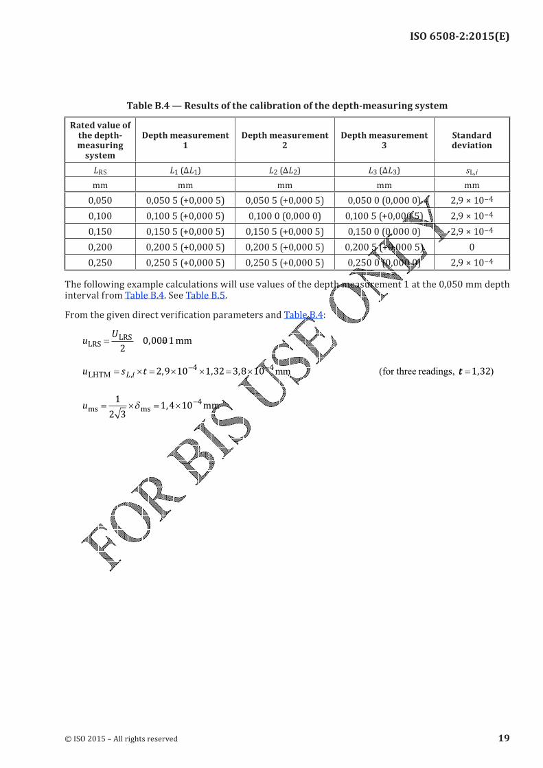
ISO 6508-2:2015(E)
Table B.4 — Results of the calibration of the depth-measuring system
Rated value of the depth- measuring
system
Depth measurement 1
Depth measurement 2
Depth measurement 3
Standard deviation
LRS L1 (ΔL1) L2 (ΔL2) L3 (ΔL3) sL ,i
mm mm mm mm mm0,050 0,050 5 (+0,000 5) 0,050 5 (+0,000 5) 0,050 0 (0,000 0) 2,9 × 10−40,100 0,100 5 (+0,000 5) 0,100 0 (0,000 0) 0,100 5 (+0,000 5) 2,9 × 10−40,150 0,150 5 (+0,000 5) 0,150 5 (+0,000 5) 0,150 0 (0,000 0) 2,9 × 10−40,200 0,200 5 (+0,000 5) 0,200 5 (+0,000 5) 0,200 5 (+0,000 5) 00,250 0,250 5 (+0,000 5) 0,250 5 (+0,000 5) 0,250 0 (0,000 0) 2,9 × 10⁻⁴The following example calculations will use values of the depth measurement 1 at the 0,050 mm depth interval from Table B.4. See Table B.5.From the given direct verification parameters and Table B.4:
uU
LRSLRS mm= =2
0 0001,
u s tL iLHTM mm (for three readings, = × = × × = ×
− −
, , , ,2 9 10 1 32 3 8 104 4
tt =1 32, )
ums ms mm= × = ×−1
2 31 4 10
4δ ,
© ISO 2015 – All rights reserved 19
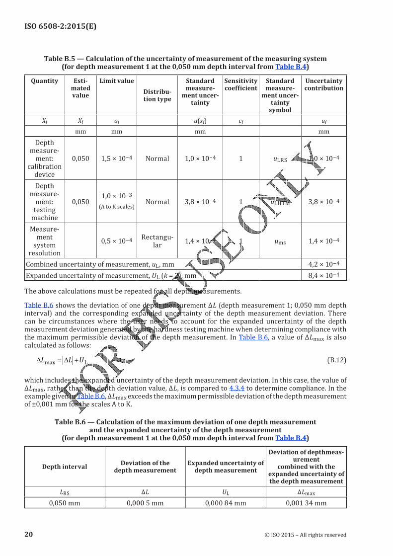
ISO 6508-2:2015(E)
Table B.5 — Calculation of the uncertainty of measurement of the measuring system (for depth measurement 1 at the 0,050 mm depth interval from Table B.4)
Quantity Esti-mated value
Limit valueDistribu-tion type
Standard measure-
ment uncer-tainty
Sensitivity coefficient
Standard measure-
ment uncer-tainty
symbol
Uncertainty contribution
Xi Xi ai u(xi) ci ui
mm mm mm mm
Depth measure-
ment: calibration
device
0,050 1,5 × 10⁻⁴ Normal 1,0 × 10⁻⁴ 1 uLRS 1,0 × 10⁻⁴Depth
measure-ment:
testing machine
0,050 1,0 × 10⁻³(A to K scales) Normal 3,8 × 10⁻⁴ 1 uLHTM 3,8 × 10⁻⁴Measure-
ment system resolution
0,5 × 10⁻⁴ Rectangu-lar
1,4 × 10⁻⁴ 1 ums 1,4 × 10⁻⁴Combined uncertainty of measurement, uL, mm 4,2 × 10⁻⁴Expanded uncertainty of measurement, UL (k = 2), mm 8,4 × 10⁻⁴The above calculations must be repeated for all depth measurements.
Table B.6 shows the deviation of one depth measurement ΔL (depth measurement 1; 0,050 mm depth interval) and the corresponding expanded uncertainty of the depth measurement deviation. There can be circumstances where the user needs to account for the expanded uncertainty of the depth measurement deviation generated by the hardness testing machine when determining compliance with the maximum permissible deviation of the depth measurement. In Table B.6, a value of ΔLmax is also calculated as follows:
∆ ∆L L Umax
= +L
(B.12)which includes the expanded uncertainty of the depth measurement deviation. In this case, the value of ΔLmax, rather than the depth deviation value, ΔL, is compared to 4.3.4 to determine compliance. In the example given in Table B.6, ΔLmax exceeds the maximum permissible deviation of the depth measurement of ±0,001 mm for the scales A to K.
Table B.6 — Calculation of the maximum deviation of one depth measurement and the expanded uncertainty of the depth measurement
(for depth measurement 1 at the 0,050 mm depth interval from Table B.4)
Depth intervalDeviation of the
depth measurementExpanded uncertainty of
depth measurement
Deviation of depthmeas-urement
combined with the expanded uncertainty of the depth measurement
LRS ΔL UL ΔLmax0,050 mm 0,000 5 mm 0,000 84 mm 0,001 34 mm
20 © ISO 2015 – All rights reserved
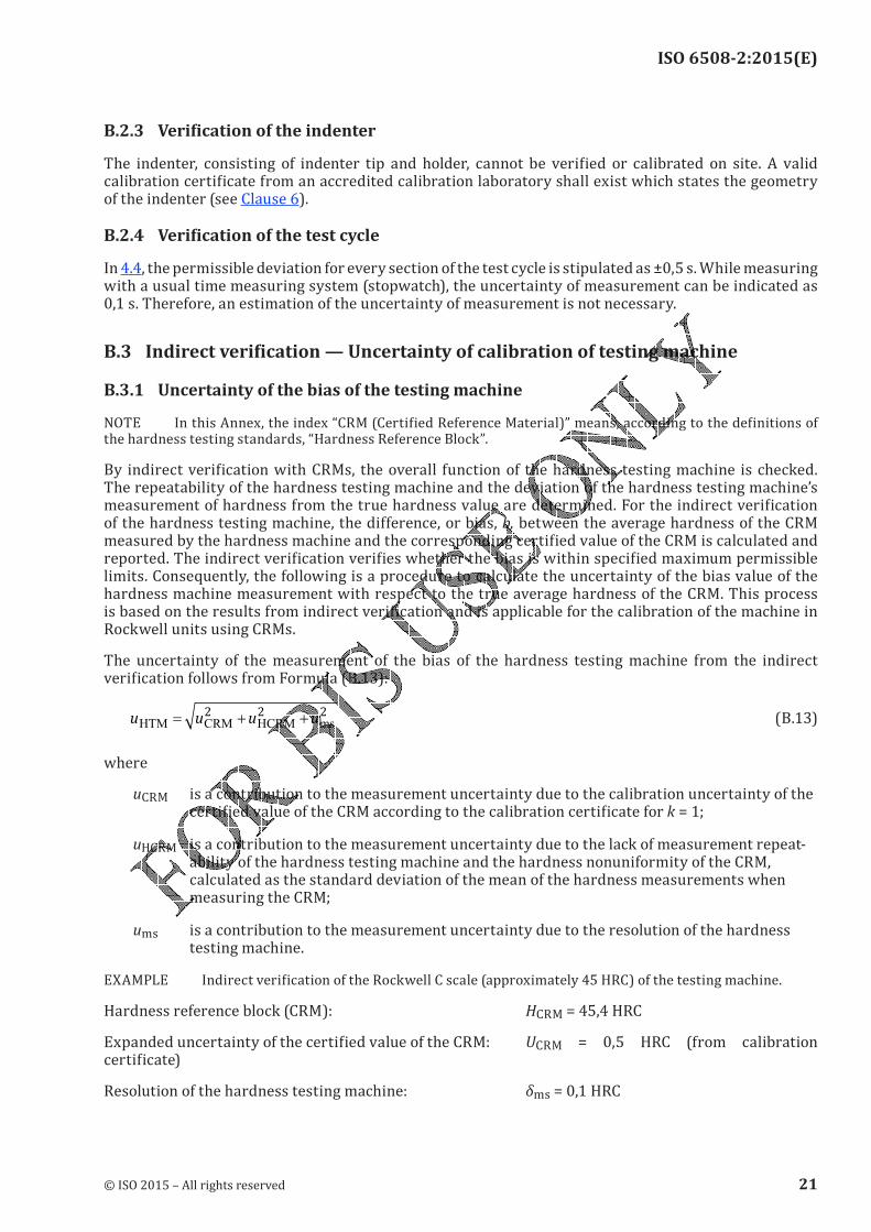
ISO 6508-2:2015(E)
B.2.3 Verification of the indenterThe indenter, consisting of indenter tip and holder, cannot be verified or calibrated on site. A valid calibration certificate from an accredited calibration laboratory shall exist which states the geometry of the indenter (see Clause 6).
B.2.4 Verification of the test cycle
In 4.4, the permissible deviation for every section of the test cycle is stipulated as ±0,5 s. While measuring with a usual time measuring system (stopwatch), the uncertainty of measurement can be indicated as 0,1 s. Therefore, an estimation of the uncertainty of measurement is not necessary.B.3 Indirect verification — Uncertainty of calibration of testing machine
B.3.1 Uncertainty of the bias of the testing machineNOTE In this Annex, the index “CRM (Certified Reference Material)” means, according to the definitions of the hardness testing standards, “Hardness Reference Block”.By indirect verification with CRMs, the overall function of the hardness testing machine is checked. The repeatability of the hardness testing machine and the deviation of the hardness testing machine’s measurement of hardness from the true hardness value are determined. For the indirect verification of the hardness testing machine, the difference, or bias, b, between the average hardness of the CRM measured by the hardness machine and the corresponding certified value of the CRM is calculated and reported. The indirect verification verifies whether the bias is within specified maximum permissible limits. Consequently, the following is a procedure to calculate the uncertainty of the bias value of the hardness machine measurement with respect to the true average hardness of the CRM. This process is based on the results from indirect verification and is applicable for the calibration of the machine in Rockwell units using CRMs.The uncertainty of the measurement of the bias of the hardness testing machine from the indirect verification follows from Formula (B.13):
u u u uHTM CRM HCRM ms= + +2 2 2 (B.13)
where
uCRM is a contribution to the measurement uncertainty due to the calibration uncertainty of the certified value of the CRM according to the calibration certificate for k = 1;
uHCRM is a contribution to the measurement uncertainty due to the lack of measurement repeat-ability of the hardness testing machine and the hardness nonuniformity of the CRM, calculated as the standard deviation of the mean of the hardness measurements when measuring the CRM;
ums is a contribution to the measurement uncertainty due to the resolution of the hardness testing machine.EXAMPLE Indirect verification of the Rockwell C scale (approximately 45 HRC) of the testing machine.
Hardness reference block (CRM): HCRM = 45,4 HRCExpanded uncertainty of the certified value of the CRM: UCRM = 0,5 HRC (from calibration certificate)Resolution of the hardness testing machine: δms = 0,1 HRC
© ISO 2015 – All rights reserved 21
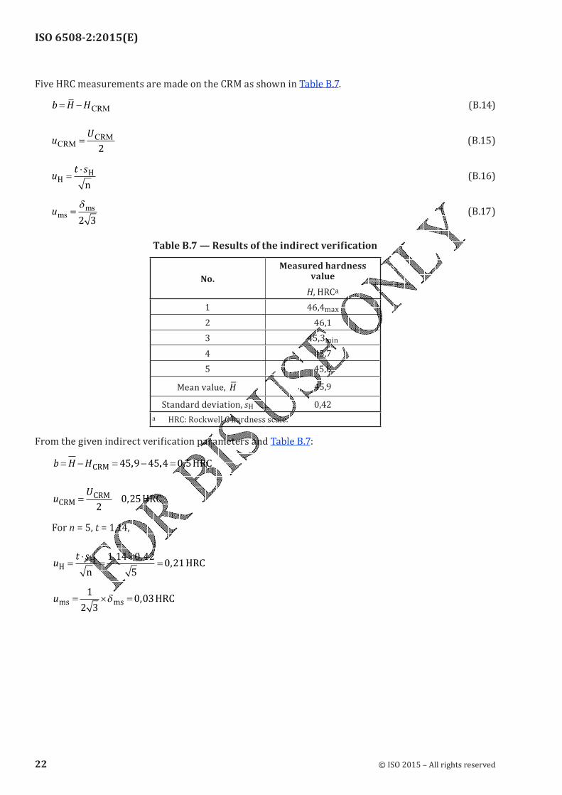
ISO 6508-2:2015(E)
Five HRC measurements are made on the CRM as shown in Table B.7.
b H H= − CRM (B.14)
uU
CRMCRM=2
(B.15)
ut s
HH
n=
⋅ (B.16)
umsms
=δ
2 3 (B.17)
Table B.7 — Results of the indirect verification
No.
Measured hardness value
H, HRCa
1 46,4max
2 46,13 45,3min
4 45,75 45,8Mean value, H 45,9Standard deviation, sH 0,42
a HRC: Rockwell C hardness scale.From the given indirect verification parameters and Table B.7:
b H H= − = − =CRM HRC45 9 45 4 0 5� � �
uU
CRMCRM
2HRC= =0 25,
For n = 5, t = 1,14,u
t s
HH
nHRC=
⋅=
×=
1 14 0 42
50 21
, ,,
ums ms HRC= × =1
2 30 03δ ,
22 © ISO 2015 – All rights reserved
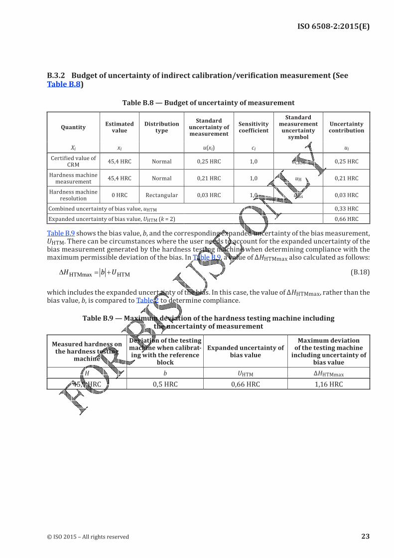
ISO 6508-2:2015(E)
B.3.2 Budget of uncertainty of indirect calibration/verification measurement (See Table B.8)
Table B.8 — Budget of uncertainty of measurement
Quantity Estimated value
Distribution type
Standard uncertainty of measurement
Sensitivity coefficient
Standard measurement
uncertainty symbol
Uncertainty contribution
Xi xi u(xi) ci uiCertified value of CRM
45,4 HRC Normal 0,25 HRC 1,0 uCRM 0,25 HRCHardness machine
measurement45,4 HRC Normal 0,21 HRC 1,0 uH 0,21 HRC
Hardness machine resolution
0 HRC Rectangular 0,03 HRC 1,0 ums 0,03 HRCCombined uncertainty of bias value, uHTM 0,33 HRCExpanded uncertainty of bias value, UHTM (k = 2) 0,66 HRCTable B.9 shows the bias value, b, and the corresponding expanded uncertainty of the bias measurement, UHTM. There can be circumstances where the user needs to account for the expanded uncertainty of the bias measurement generated by the hardness testing machine when determining compliance with the maximum permissible deviation of the bias. In Table B.9, a value of ΔHHTMmax also calculated as follows:
∆H b UHTMmax HTM= + (B.18)which includes the expanded uncertainty of the bias. In this case, the value of ΔHHTMmax, rather than the bias value, b, is compared to Table 2 to determine compliance.
Table B.9 — Maximum deviation of the hardness testing machine including the uncertainty of measurement
Measured hardness on the hardness testing
machine
Deviation of the testing machine when calibrat-ing with the reference
block
Expanded uncertainty of bias value
Maximum deviation of the testing machine
including uncertainty of bias value
H b UHTM ΔHHTMmax45,9 HRC 0,5 HRC 0,66 HRC 1,16 HRC
© ISO 2015 – All rights reserved 23
ISO 6508-2:2015(E)
Bibliography
[1] Sawla A. Uncertainty of measurement in the verification and calibration of the force measuring systems of testing machines. Proceedings of the Asia-Pacific symposium on measurement of force, mass and torque (APMF), Tsukuba, Japan, November 2000
[2] Wehrstedt A., & Patkovszky I. News in the field of standardization about verification and calibration of materials testing machines, May 2001. EMPA Academy, 2001[3] Gabauer W. Manual codes of practice for the determination of uncertainties in mechanical tests on
metallic materials, The estimation of uncertainties in hardness measurements, Project No. SMT4-CT97-2165, UNCERT COP 14:2000[4] Polzin T., & Schwenk D. Method for Uncertainty Determination of Hardness Testing; PC File for Determination, Materialprufung 44 (2002) 3, pp. 64-71.[5] ISO/IEC 17025, General requirements for the competence of testing and calibration laboratories[6] ISO/IEC 17011, Conformity assessment — General requirements for accreditation bodies accrediting
conformity assessment bodies
24 © ISO 2015 – All rights reserved


ISO 6508-2:2015(E)
ICS 77.040.10Price based on 24 pages
© ISO 2015 – All rights reserved
© ISO 2015
Metallic materials — Rockwell hardness test —
Part 3: Calibration of reference blocks
Matériaux métalliques — Essai de dureté Rockwell —
Partie 3: Étalonnage des blocs de référence
INTERNATIONAL STANDARD
ISO6508-3
Third edition2015-03-01
Reference numberISO 6508-3:2015(E)

ISO 6508-3:2015(E)
ii © ISO 2015 – All rights reserved
COPYRIGHT PROTECTED DOCUMENT
© ISO 2015All rights reserved. Unless otherwise specified, no part of this publication may be reproduced or utilized otherwise in any form or by any means, electronic or mechanical, including photocopying, or posting on the internet or an intranet, without prior written permission. Permission can be requested from either ISO at the address below or ISO’s member body in the country of the requester.ISO copyright office
Case postale 56 • CH-1211 Geneva 20Tel. + 41 22 749 01 11Fax + 41 22 749 09 47E-mail [email protected] www.iso.orgPublished in Switzerland
ISO 6508-3:2015(E)
Foreword ........................................................................................................................................................................................................................................iv
1 Scope ................................................................................................................................................................................................................................. 1
2 Normative references ...................................................................................................................................................................................... 1
3 Manufacture of reference blocks ......................................................................................................................................................... 1
4 Calibration machine and calibration indenter ..................................................................................................................... 24.1 General ........................................................................................................................................................................................................... 24.2 Calibration machine ........................................................................................................................................................................... 24.3 Calibration diamond indenter ................................................................................................................................................... 24.4 Calibration ball indenter ................................................................................................................................................................. 4
5 Calibration procedure ..................................................................................................................................................................................... 4
6 Number of indentations ................................................................................................................................................................................ 5
7 Uniformity of hardness .................................................................................................................................................................................. 5
8 Marking .......................................................................................................................................................................................................................... 6
9 Calibrationcertificate ..................................................................................................................................................................................... 7
10 Validity ............................................................................................................................................................................................................................ 7
Annex A (normative) Uniformity of reference blocks ........................................................................................................................ 8
Annex B (informative) Uncertainty of the mean hardness value of hardness-reference blocks ........10
Annex C (normative) Requirements for reference diamond indenters ........................................................................16
Bibliography .............................................................................................................................................................................................................................17
© ISO 2015 – All rights reserved iii
Contents Page

ISO 6508-3:2015(E)
ForewordISO (the International Organization for Standardization) is a worldwide federation of national standards bodies (ISO member bodies). The work of preparing International Standards is normally carried out through ISO technical committees. Each member body interested in a subject for which a technical committee has been established has the right to be represented on that committee. International organizations, governmental and non-governmental, in liaison with ISO, also take part in the work. ISO collaborates closely with the International Electrotechnical Commission (IEC) on all matters of electrotechnical standardization.The procedures used to develop this document and those intended for its further maintenance are described in the ISO/IEC Directives, Part 1. In particular the different approval criteria needed for the different types of ISO documents should be noted. This document was drafted in accordance with the editorial rules of the ISO/IEC Directives, Part 2 (see www.iso.org/directives).Attention is drawn to the possibility that some of the elements of this document may be the subject of patent rights. ISO shall not be held responsible for identifying any or all such patent rights. Details of any patent rights identified during the development of the document will be in the Introduction and/or on the ISO list of patent declarations received (see www.iso.org/patents).Any trade name used in this document is information given for the convenience of users and does not constitute an endorsement.For an explanation on the meaning of ISO specific terms and expressions related to conformity assessment, as well as information about ISO’s adherence to the WTO principles in the Technical Barriers to Trade (TBT) see the following URL: Foreword - Supplementary informationThe committee responsible for this document is ISO/TC 164, Mechanical testing of metals, Subcommittee SC 3, Hardness testing.
This third edition cancels and replaces the second edition (ISO 6508-3:2005), which has been technically revised.ISO 6508 consists of the following parts, under the general title Metallic materials — Rockwell hardness test:
— Part 1: Test method
— Part 2: Verification and calibration of testing machines and indenters
— Part 3: Calibration of reference blocks
iv © ISO 2015 – All rights reserved
Metallic materials — Rockwell hardness test —
Part 3: Calibration of reference blocks
1 ScopeThis part of ISO 6508 specifies a method for the calibration of reference blocks to be used for the indirect and daily verification of Rockwell hardness testing machines, as specified in ISO 6508-2:2015.Attention is drawn to the fact that the use of hard metal for ball indenters is considered to be the standard type of Rockwell indenter ball. Steel indenter balls can be used only when complying with ISO 6508-1:2015, Annex A.2 Normative referencesThe following documents, in whole or in part, are normatively referenced in this document and are indispensable for its application. For dated references, only the edition cited applies. For undated references, the latest edition of the referenced document (including any amendments) applies.ISO 376, Metallic materials — Calibration of force-proving instruments used for the verification of uniaxial testing machinesISO 6508-1:2015, Metallic materials — Rockwell hardness test — Part 1: Test methodISO 6508-2:2015, Metallic materials — Rockwell hardness test — Part 2: Verification and calibration of testing machines and indenters
3 Manufacture of reference blocks
3.1 The block shall be specially manufactured for use as a hardness-reference block.NOTE Attention is drawn to the need to use a manufacturing process, which will give the necessary homogeneity, stability of structure, and uniformity of surface hardness.3.2 Each hardness reference block shall be of a thickness not less than 6 mm. To minimize the effect of hardness change with increasing number of indents, thicker blocks should be used.3.3 The reference blocks shall be free of magnetism. It is recommended that the manufacturer ensure that the blocks, if made of steel, have been demagnetized at the end of the manufacturing process (before calibration).
3.4 The deviation from surface flatness of the top and bottom surfaces shall be ≤0,01 mm. The bottom of the blocks shall not be convex. The deviation from parallelism of the top and bottom surfaces shall be ≤0,02 mm per 50 mm.3.5 The test surface and lower surface shall be free from damage, such as notches, scratches, oxide layers, etc., which can interfere with the measurement of the indentations. The surface roughness, Ra, shall not exceed 0,000 3 mm for the test surface and 0,000 8 mm for the bottom surface. Sampling length is l = 0,8 mm (see ISO 4287:1997, 3.1.9).
INTERNATIONAL STANDARD ISO 6508-3:2015(E)
© ISO 2015 – All rights reserved 1
ISO 6508-3:2015(E)
3.6 To verify that no material is subsequently removed from the reference block, the thickness at the time of calibration shall be marked on it, to the nearest 0,1 mm, or an identifying mark shall be made on the test surface [see 8.1 e)].
4 Calibration machine and calibration indenter
4.1 General
4.1.1 Calibrations and verifications of Rockwell calibration machines and calibration indenters shall be carried out at a temperature of (23 ± 5) °C.
4.1.2 The instruments used for calibration shall be traceable to national standards.
4.2 Calibration machine
4.2.1 In addition to fulfilling the general conditions specified in ISO 6508-2:2015, Clause 3, the calibration machine shall also meet the requirements given in 4.2.2, 4.2.3, 4.2.4, 4.2.5, and 4.2.6.
4.2.2 The machine shall be directly verified in intervals not exceeding 12 months. Direct verification involves calibration and verification of the following:a) test force;b) measuring system;c) testing cycle; if this is not possible, at least the force versus time behaviour.4.2.3 The test force shall be measured by means of an elastic proving device (according to ISO 376) class 0,5 or better and calibrated for reversibility, or by another method having the same or better accuracy.Evidence should be available to demonstrate that the output of the force-proving device does not vary by more than 0,1 % in a period of 1 s to 30 s, following a stepped change in force.4.2.4 Each test force shall be measured and shall agree with the nominal preliminary test force, F0, to within ±0,2 % and the nominal total test force, F, to within ±0,1 %.4.2.5 The measuring system shall have a resolution of ±0,000 1 mm and a maximum expanded uncertainty of 0,000 2 mm, when calculated with a confidence level of 95 % over its working range.4.2.6 The testing cycle shall be timed with an uncertainty less than ±0,5 s and shall conform to the testing cycle of Clause 5.
4.3 Calibration diamond indenter
4.3.1 The geometric shape and performance of calibration diamond indenters shall be calibrated as defined below. Direct verification of the geometric shape shall be made before first use and at a frequency of no greater than five years. Verification of the indenter performance, as specified in 4.3.3, shall be made before first use and at a frequency of no greater than 12 months.4.3.2 The diamond indenter shall be measured on at least eight unique axial section planes equidistant from each other (e.g. the eight cross-sections will be spaced approximately 22,5° apart at 0°, 22,5°, 45°, 67,5°, 90°, 112,5°, 135°, 157,5°), and shall meet the following requirements:
2 © ISO 2015 – All rights reserved
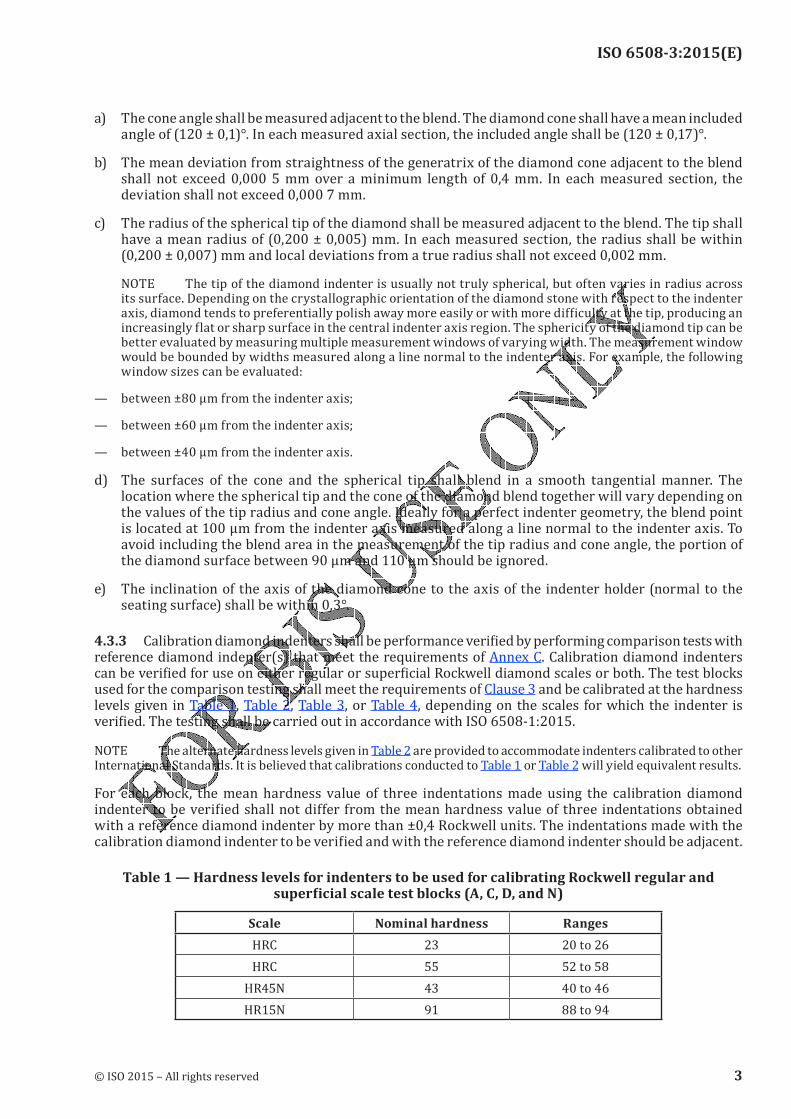
ISO 6508-3:2015(E)
a) The cone angle shall be measured adjacent to the blend. The diamond cone shall have a mean included angle of (120 ± 0,1)°. In each measured axial section, the included angle shall be (120 ± 0,17)°.b) The mean deviation from straightness of the generatrix of the diamond cone adjacent to the blend shall not exceed 0,000 5 mm over a minimum length of 0,4 mm. In each measured section, the deviation shall not exceed 0,000 7 mm.c) The radius of the spherical tip of the diamond shall be measured adjacent to the blend. The tip shall have a mean radius of (0,200 ± 0,005) mm. In each measured section, the radius shall be within (0,200 ± 0,007) mm and local deviations from a true radius shall not exceed 0,002 mm.NOTE The tip of the diamond indenter is usually not truly spherical, but often varies in radius across its surface. Depending on the crystallographic orientation of the diamond stone with respect to the indenter axis, diamond tends to preferentially polish away more easily or with more difficulty at the tip, producing an increasingly flat or sharp surface in the central indenter axis region. The sphericity of the diamond tip can be better evaluated by measuring multiple measurement windows of varying width. The measurement window would be bounded by widths measured along a line normal to the indenter axis. For example, the following window sizes can be evaluated:— between ±80 µm from the indenter axis;
— between ±60 µm from the indenter axis;
— between ±40 µm from the indenter axis.
d) The surfaces of the cone and the spherical tip shall blend in a smooth tangential manner. The location where the spherical tip and the cone of the diamond blend together will vary depending on the values of the tip radius and cone angle. Ideally for a perfect indenter geometry, the blend point is located at 100 µm from the indenter axis measured along a line normal to the indenter axis. To avoid including the blend area in the measurement of the tip radius and cone angle, the portion of the diamond surface between 90 µm and 110 µm should be ignored.
e) The inclination of the axis of the diamond cone to the axis of the indenter holder (normal to the seating surface) shall be within 0,3°.4.3.3 Calibration diamond indenters shall be performance verified by performing comparison tests with reference diamond indenter(s) that meet the requirements of Annex C. Calibration diamond indenters can be verified for use on either regular or superficial Rockwell diamond scales or both. The test blocks used for the comparison testing shall meet the requirements of Clause 3 and be calibrated at the hardness levels given in Table 1, Table 2, Table 3, or Table 4, depending on the scales for which the indenter is verified. The testing shall be carried out in accordance with ISO 6508-1:2015.NOTE The alternate hardness levels given in Table 2 are provided to accommodate indenters calibrated to other International Standards. It is believed that calibrations conducted to Table 1 or Table 2 will yield equivalent results.For each block, the mean hardness value of three indentations made using the calibration diamond indenter to be verified shall not differ from the mean hardness value of three indentations obtained with a reference diamond indenter by more than ±0,4 Rockwell units. The indentations made with the calibration diamond indenter to be verified and with the reference diamond indenter should be adjacent.
Table 1 — Hardness levels for indenters to be used for calibrating Rockwell regular and superficialscaletestblocks(A,C,D,andN)
Scale Nominal hardness Ranges
HRC 23 20 to 26
HRC 55 52 to 58
HR45N 43 40 to 46
HR15N 91 88 to 94
© ISO 2015 – All rights reserved 3
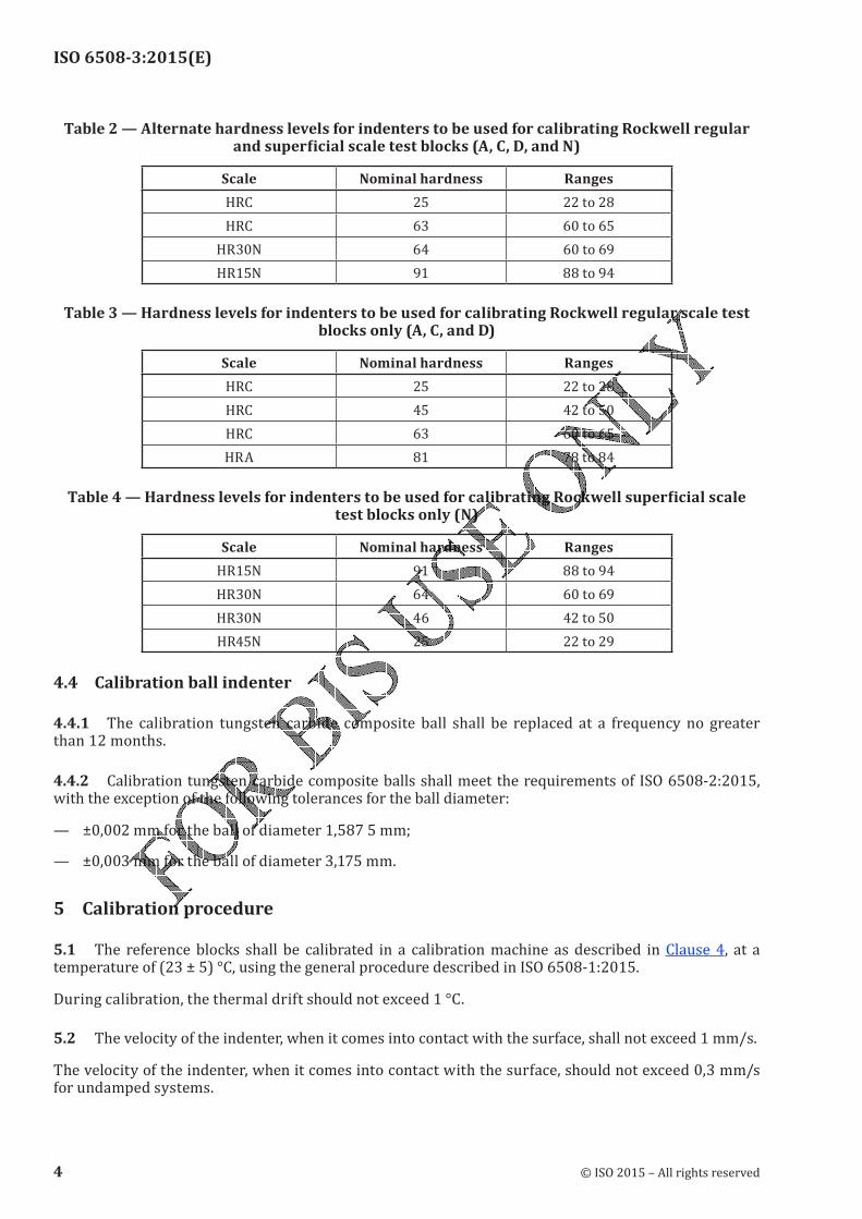
ISO 6508-3:2015(E)
Table 2 — Alternate hardness levels for indenters to be used for calibrating Rockwell regular andsuperficialscaletestblocks(A,C,D,andN)
Scale Nominal hardness Ranges
HRC 25 22 to 28
HRC 63 60 to 65
HR30N 64 60 to 69
HR15N 91 88 to 94
Table 3 — Hardness levels for indenters to be used for calibrating Rockwell regular scale test blocksonly(A,C,andD)
Scale Nominal hardness Ranges
HRC 25 22 to 28
HRC 45 42 to 50
HRC 63 60 to 65
HRA 81 78 to 84
Table4—HardnesslevelsforindenterstobeusedforcalibratingRockwellsuperficialscaletest blocks only (N)
Scale Nominal hardness Ranges
HR15N 91 88 to 94
HR30N 64 60 to 69
HR30N 46 42 to 50
HR45N 25 22 to 29
4.4 Calibration ball indenter
4.4.1 The calibration tungsten carbide composite ball shall be replaced at a frequency no greater than 12 months.
4.4.2 Calibration tungsten carbide composite balls shall meet the requirements of ISO 6508-2:2015, with the exception of the following tolerances for the ball diameter:— ±0,002 mm for the ball of diameter 1,587 5 mm;— ±0,003 mm for the ball of diameter 3,175 mm.5 Calibration procedure
5.1 The reference blocks shall be calibrated in a calibration machine as described in Clause 4, at a temperature of (23 ± 5) °C, using the general procedure described in ISO 6508-1:2015.During calibration, the thermal drift should not exceed 1 °C.5.2 The velocity of the indenter, when it comes into contact with the surface, shall not exceed 1 mm/s.The velocity of the indenter, when it comes into contact with the surface, should not exceed 0,3 mm/s for undamped systems.
4 © ISO 2015 – All rights reserved
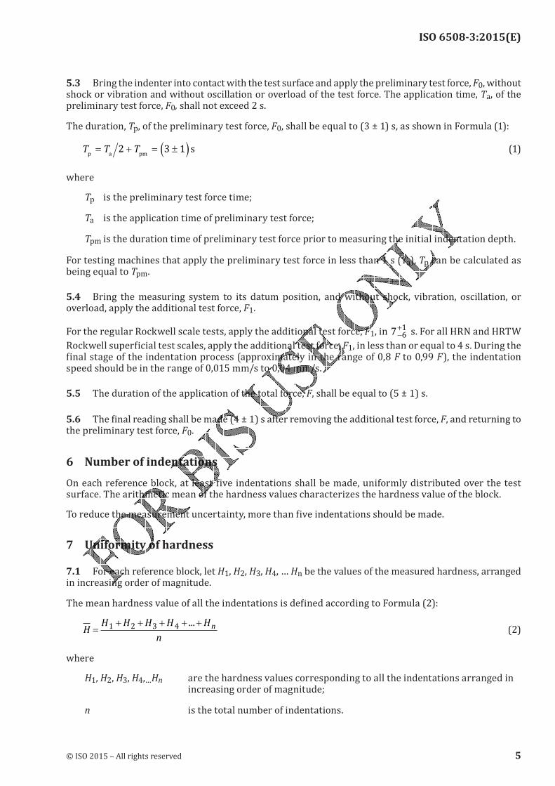
ISO 6508-3:2015(E)
5.3 Bring the indenter into contact with the test surface and apply the preliminary test force, F0, without shock or vibration and without oscillation or overload of the test force. The application time, Ta, of the preliminary test force, F0, shall not exceed 2 s.The duration, Tp, of the preliminary test force, F0, shall be equal to (3 ± 1) s, as shown in Formula (1):T T Tp a pm
s= + = ±( )2 3 1 (1)
where
Tp is the preliminary test force time;Ta is the application time of preliminary test force;Tpm is the duration time of preliminary test force prior to measuring the initial indentation depth.For testing machines that apply the preliminary test force in less than 1 s (Ta), Tp can be calculated as
being equal to Tpm.
5.4 Bring the measuring system to its datum position, and without shock, vibration, oscillation, or overload, apply the additional test force, F1.For the regular Rockwell scale tests, apply the additional test force, F1, in 7 61−
+ s. For all HRN and HRTW Rockwell superficial test scales, apply the additional test force, F1, in less than or equal to 4 s. During the final stage of the indentation process (approximately in the range of 0,8 F to 0,99 F), the indentation speed should be in the range of 0,015 mm/s to 0,04 mm/s.5.5 The duration of the application of the total force, F, shall be equal to (5 ± 1) s.5.6 The final reading shall be made (4 ± 1) s after removing the additional test force, F, and returning to the preliminary test force, F0.
6 Number of indentationsOn each reference block, at least five indentations shall be made, uniformly distributed over the test surface. The arithmetic mean of the hardness values characterizes the hardness value of the block.To reduce the measurement uncertainty, more than five indentations should be made.7 Uniformity of hardness
7.1 For each reference block, let H1, H2, H3, H4, … Hn be the values of the measured hardness, arranged in increasing order of magnitude.The mean hardness value of all the indentations is defined according to Formula (2):
HH H H H H
n
n=+ + + + +1 2 3 4 ...
(2)
where
H1, H2, H3, H4,…Hn are the hardness values corresponding to all the indentations arranged in increasing order of magnitude;
n is the total number of indentations.
© ISO 2015 – All rights reserved 5
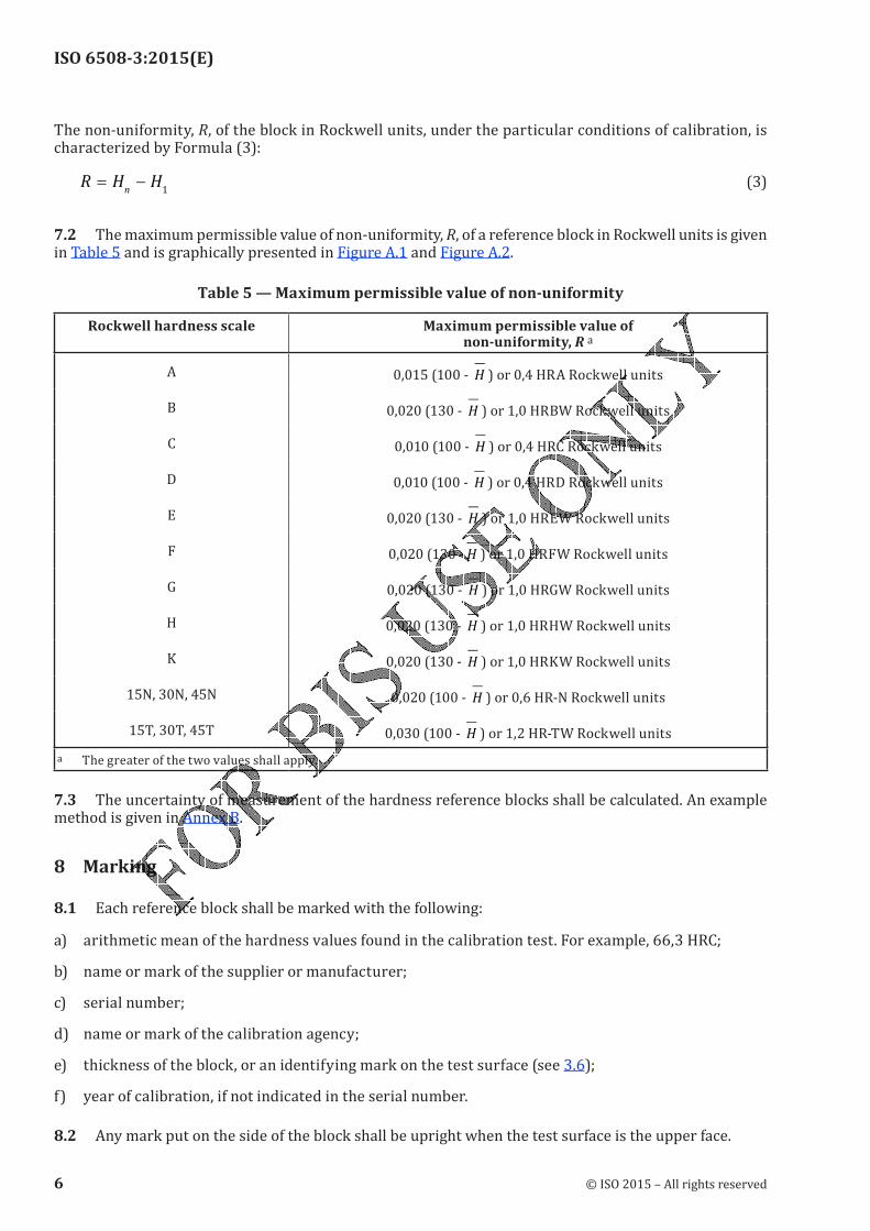
ISO 6508-3:2015(E)
The non-uniformity, R, of the block in Rockwell units, under the particular conditions of calibration, is characterized by Formula (3):R H H
n= −
1 (3)
7.2 The maximum permissible value of non-uniformity, R, of a reference block in Rockwell units is given in Table 5 and is graphically presented in Figure A.1 and Figure A.2.
Table 5 — Maximum permissible value of non-uniformity
Rockwell hardness scale Maximum permissible value of non-uniformity,R a
A 0,015 (100 - H ) or 0,4 HRA Rockwell unitsB 0,020 (130 - H ) or 1,0 HRBW Rockwell unitsC 0,010 (100 - H ) or 0,4 HRC Rockwell unitsD 0,010 (100 - H ) or 0,4 HRD Rockwell unitsE 0,020 (130 - H ) or 1,0 HREW Rockwell unitsF 0,020 (130 - H ) or 1,0 HRFW Rockwell unitsG 0,020 (130 - H ) or 1,0 HRGW Rockwell unitsH 0,020 (130 - H ) or 1,0 HRHW Rockwell unitsK 0,020 (130 - H ) or 1,0 HRKW Rockwell units15N, 30N, 45N 0,020 (100 - H ) or 0,6 HR-N Rockwell units15T, 30T, 45T 0,030 (100 - H ) or 1,2 HR-TW Rockwell units
a The greater of the two values shall apply.7.3 The uncertainty of measurement of the hardness reference blocks shall be calculated. An example method is given in Annex B.
8 Marking
8.1 Each reference block shall be marked with the following:a) arithmetic mean of the hardness values found in the calibration test. For example, 66,3 HRC;b) name or mark of the supplier or manufacturer;
c) serial number;d) name or mark of the calibration agency;e) thickness of the block, or an identifying mark on the test surface (see 3.6);f) year of calibration, if not indicated in the serial number.8.2 Any mark put on the side of the block shall be upright when the test surface is the upper face.
6 © ISO 2015 – All rights reserved
ISO 6508-3:2015(E)
9 Calibrationcertificate
9.1 Each delivered reference block shall be accompanied with a document giving at least the following information:
a) reference to this part of ISO 6508 (i.e. ISO 6508-3);b) identity of the block;c) date of calibration;
d) individual calibration results;
e) arithmetic mean of the hardness values;f) value characterizing the non-uniformity of the block (see 7.1);g) statement of uncertainty.10 ValidityThe hardness reference block is only valid for the scale for which it was calibrated.The calibration validity should be limited to a duration of five years. Attention is drawn to the fact that, for Al-alloys and Cu-alloys, the calibration validity could be reduced to two years to three years.The calibration result is only valid for the reference block at the time of calibration. The hardness of the block can be changed by repeated test on the block and attention must be drawn to the fact that it might not be negligible when the number of indentation is large.
© ISO 2015 – All rights reserved 7
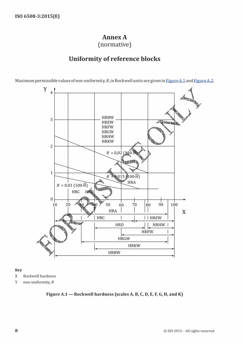
ISO 6508-3:2015(E)
Annex A (normative)
Uniformity of reference blocks
Maximum permissible values of non-uniformity, R, in Rockwell units are given in Figure A.1 and Figure A.2.
HRKWHRHWHRGWHRFWHREWHRBW
4
3
2
1
0
HRDHRC
20 30 40
HRA
50 60 70 9080 100
Y
X
R = 0,01 (100-H)
R = 0,015 (100-H)
R = 0,02 (130-H)
10
HRGW
HRD
HRKW
HRFW
HREW
HRHW
HRA
HRBW
HRC
Key
X Rockwell hardness
Y non-uniformity, RFigureA.1—Rockwellhardness(scalesA,B,C,D,E,F,G,H,andK)
8 © ISO 2015 – All rights reserved
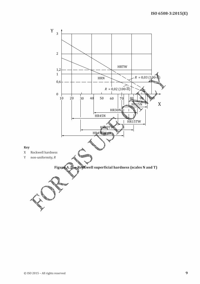
ISO 6508-3:2015(E)
3
2
0,6
1,2
1
10
0
20
HRN
4030 50
HRTW
60 70 80 90 100
Y
X
R = 0,03 (100-H)
R = 0,02 (100-H)
HR45N
HR45TW
HR15N
HR15TW
HR30N
HR30TW
Key
X Rockwell hardness
Y non-uniformity, RFigureA.2—Rockwellsuperficialhardness(scalesNandT)
© ISO 2015 – All rights reserved 9
ISO 6508-3:2015(E)
Annex B (informative)
Uncertainty of the mean hardness value of hardness-reference
blocks
B.1 GeneralMeasurement uncertainty analysis is a useful tool to help determine sources of error and to understand differences between measured values. This Annex gives guidance on uncertainty estimation, but the methods contained are for information only, unless specifically instructed otherwise by the customer. The criteria specified in this International Standard for the calibration requirements of the reference block have been developed and refined over a significant period of time. When determining a specific tolerance that the reference block needs to meet, the uncertainty associated with the use of measuring equipment has been incorporated within this tolerance and therefore, it would be inappropriate to make any further allowance for this uncertainty, for example, by reducing the tolerance by the measurement uncertainty. This applies to all measurements associated with the manufacture and calibration of the reference blocks and also to all measurements made when performing a verification of the calibration machine. In each case, it is simply the measured value resulting from the use of the specified measuring equipment that is used to assess compliance with this International Standard. However, there might be special circumstances where reducing the tolerance by the measurement uncertainty is appropriate. This should only be done by agreement of the parties involved.NOTE The metrological chain necessary to define and disseminate hardness scales is shown in ISO 6508-1:2015, Figure I.1.B.2 Directverification-uncertaintyofcalibrationofmachinecomponents
B.2.1 CalibrationandverificationofthetestforceSee ISO 6508-2:2015, Annex B.B.2.2 Calibrationandverificationofthedepth-measuringdeviceSee ISO 6508-2:2015, Annex B.B.2.3 VerificationoftheindenterSee ISO 6508-2:2015, Annex B.B.2.4 VerificationofthetestcycleSee ISO 6508-2:2105, Annex B.B.3 Indirectverification-uncertaintyofcalibrationofcalibrationmachineNOTE 1 In this Annex, the index “CRM-P (certified reference material-primary)” means “primary hardness reference block”.NOTE 2 The result of indirect verification is used for the evaluation of the uncertainty of calibration of the hardness calibration machine.
10 © ISO 2015 – All rights reserved
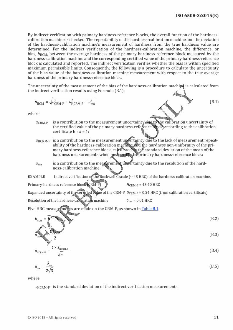
ISO 6508-3:2015(E)
By indirect verification with primary hardness-reference blocks, the overall function of the hardness-calibration machine is checked. The repeatability of the hardness-calibration machine and the deviation of the hardness-calibration machine’s measurement of hardness from the true hardness value are determined. For the indirect verification of the hardness-calibration machine, the difference, or bias, bHCM, between the average hardness of the primary hardness-reference block measured by the hardness-calibration machine and the corresponding certified value of the primary hardness-reference block is calculated and reported. The indirect verification verifies whether the bias is within specified maximum permissible limits. Consequently, the following is a procedure to calculate the uncertainty of the bias value of the hardness-calibration machine measurement with respect to the true average hardness of the primary hardness-reference block.The uncertainty of the measurement of the bias of the hardness-calibration machine is calculated from the indirect verification results using Formula (B.1):
u u u uHCM CRM-P HCRM-P ms
= + +2 2 2 (B.1)where
uCRM-P is a contribution to the measurement uncertainty due to the calibration uncertainty of the certified value of the primary hardness-reference block, according to the calibration certificate for k = 1;
uHCRM-P is a contribution to the measurement uncertainty due to the lack of measurement repeat-ability of the hardness-calibration machine and the hardness non-uniformity of the pri-mary hardness-reference block, calculated as the standard deviation of the mean of the hardness measurements when measuring the primary hardness-reference block;ums is a contribution to the measurement uncertainty due to the resolution of the hard-
ness-calibration machine.EXAMPLE Indirect verification of the Rockwell C scale (~ 45 HRC) of the hardness-calibration machine.Primary-hardness reference block (CRM-P) HCRM-P = 45,40 HRCExpanded uncertainty of the certified value of the CRM-P UCRM-P = 0,24 HRC (from calibration certificate)Resolution of the hardness-calibration machine δms = 0,01 HRCFive HRC measurements are made on the CRM-P, as shown in Table B.1.
b H HHCM CRM-P
= − (B.2)u
U
CRM-P
CRM-P=2
(B.3)u
t s
nHCRM-P
HCRM-P=
× (B.4)ums
ms=δ
2 3
(B.5)where
sHCRM-P is the standard deviation of the indirect verification measurements.
© ISO 2015 – All rights reserved 11
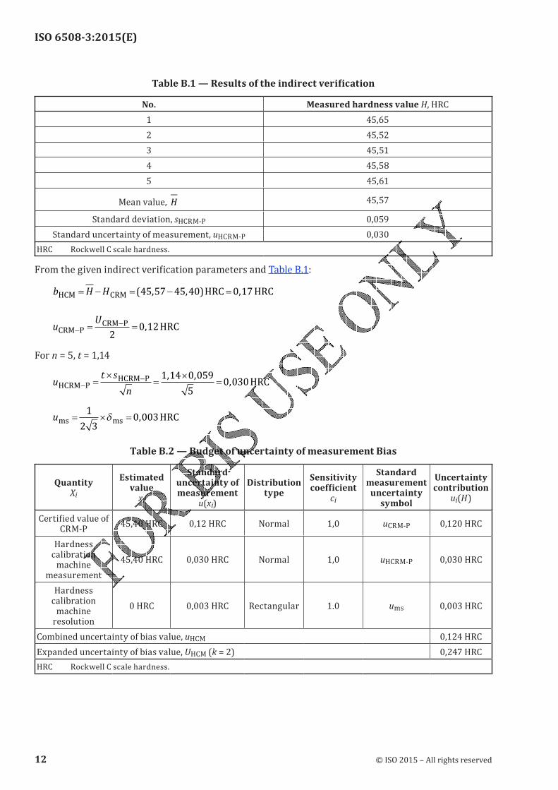
ISO 6508-3:2015(E)
TableB.1—Resultsoftheindirectverification
No. Measured hardness value H, HRC1 45,652 45,523 45,514 45,585 45,61Mean value, H 45,57Standard deviation, sHCRM-P 0,059Standard uncertainty of measurement, uHCRM-P 0,030
HRC Rockwell C scale hardness.From the given indirect verification parameters and Table B.1:
b H HHCM CRM
HRC HRC= − = − =( , , ) ,45 57 45 40 0 17
uU
CRM PCRM P HRC−
−= =
20 12,
For n = 5, t = 1,14u
t s
nHCRM P
HCRM PHRC−
−=
×=
×=
1 14 0 059
50 030
, ,,
ums ms
HRC= × =1
2 30 003δ ,
Table B.2 — Budget of uncertainty of measurement Bias
Quantity Xi
Estimated value
xi
Standard uncertainty of measurement
u(xi)
Distribution type
Sensitivity coefficient
ci
Standard measurement
uncertainty symbol
Uncertainty contribution
ui(H)Certified value of CRM-P
45,40 HRC 0,12 HRC Normal 1,0 uCRM-P 0,120 HRCHardness
calibration machine
measurement
45,40 HRC 0,030 HRC Normal 1,0 uHCRM-P 0,030 HRCHardness
calibration machine
resolution
0 HRC 0,003 HRC Rectangular 1.0 ums 0,003 HRCCombined uncertainty of bias value, uHCM 0,124 HRCExpanded uncertainty of bias value, UHCM (k = 2) 0,247 HRCHRC Rockwell C scale hardness.
12 © ISO 2015 – All rights reserved
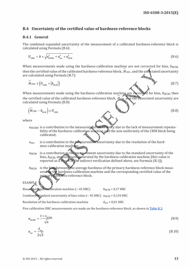
ISO 6508-3:2015(E)
B.4 Uncertaintyofthecertifiedvalueofhardness-referenceblocks
B.4.1 GeneralThe combined expanded uncertainty of the measurement of a calibrated hardness-reference block is calculated using Formula (B.6):U k u u uCRM HCRM ms HCM
= × + +2 2 2 (B.6)When measurements made using the hardness-calibration machine are not corrected for bias, bHCM, then the certified value of the calibrated hardness-reference block, HCRM , and the associated uncertainty are calculated using Formula (B.7):
H U bCRMCRM HCM
± +( ) (B.7)When measurements made using the hardness-calibration machine are corrected for bias, bHCM, then the certified value of the calibrated hardness-reference block, HCRM and the associated uncertainty are calculated using Formula (B.8):H b UCRM
HCM CRM−( ) ± (B.8)
where
uHCRM is a contribution to the measurement uncertainty due to the lack of measurement repeata-bility of the hardness-calibration machine and the non-uniformity of the CRM block being calibrated;
ums is a contribution to the measurement uncertainty due to the resolution of the hard-ness-calibration machine;
uHCM is a contribution to the measurement uncertainty due to the standard uncertainty of the bias, bHCM, measurement generated by the hardness-calibration machine [this value is reported as a result of the indirect verification defined above, see Formula (B.1)];bHCM is the bias between the average hardness of the primary hardness-reference block meas-ured by the hardness-calibration machine and the corresponding certified value of the primary hardness-reference block.
EXAMPLE Bias of hardness-calibration machine (~ 45 HRC) bHCM = 0,17 HRCCombined standard uncertainty of bias value (~ 45 HRC) uHCM = 0,124 HRCResolution of the hardness-calibration machine δms = 0,01 HRCFive calibration HRC measurements are made on the hardness-reference block, as shown in Table B.3.
ut s
nHCRM
HCRM=
× (B.9)ums
ms=δ
2 3
(B.10)
© ISO 2015 – All rights reserved 13
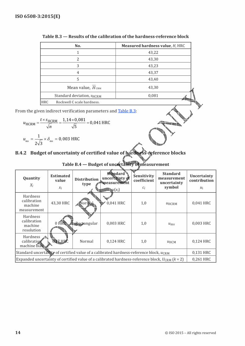
ISO 6508-3:2015(E)
Table B.3 — Results of the calibration of the hardness-reference block
No. Measured hardness value, H, HRC1 43,222 43,303 43,234 43,375 43,40 Mean value, H CRM 43,30Standard deviation, sHCRM 0,081
HRC Rockwell C scale hardness.From the given indirect verification parameters and Table B.3:
ut s
nHCRM
HCRMHRC=
×=
×=
1 14 0 081
50 041
, ,,
ums ms
HRC= × =1
2 3
0 003δ ,
B.4.2 Budgetofuncertaintyofcertifiedvalueofhardness-referenceblocks
Table B.4 — Budget of uncertainty of measurement
Quantity
Xi
Estimated value
xi
Distribution type
Standard uncertainty of measurement
u(xi)
Sensitivity coefficient
ci
Standard measurement
uncertainty symbol
Uncertainty contribution
ui
Hardness calibration
machine measurement
43,30 HRC Normal 0,041 HRC 1,0 uHCRM 0,041 HRCHardness
calibration machine
resolution
0 HRC Rectangular 0,003 HRC 1,0 ums 0,003 HRCHardness
calibration machine bias
0,17 HRC Normal 0,124 HRC 1,0 uHCM 0,124 HRCStandard uncertainty of certified value of a calibrated hardness-reference block, uCRM 0,131 HRCExpanded uncertainty of certified value of a calibrated hardness-reference block, UCRM (k = 2) 0,261 HRC
14 © ISO 2015 – All rights reserved
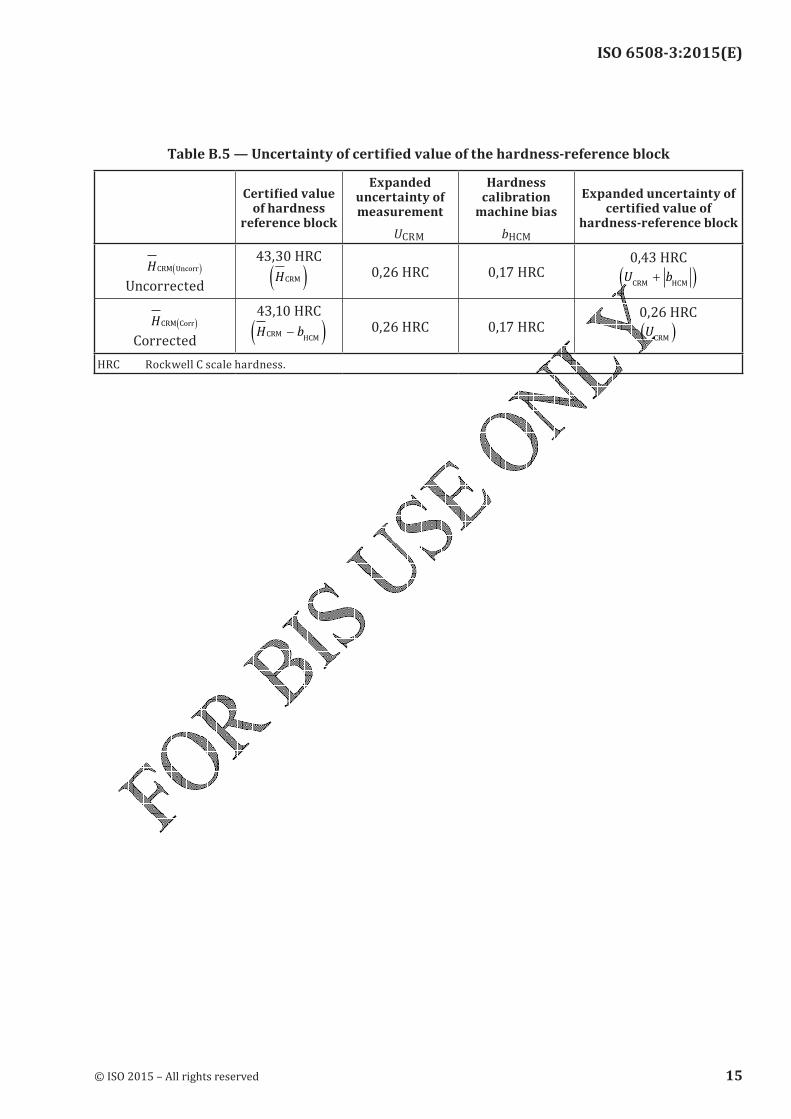
ISO 6508-3:2015(E)
TableB.5—Uncertaintyofcertifiedvalueofthehardness-referenceblock
Certifiedvalueof hardness
reference block
Expanded uncertainty of measurement
UCRM
Hardness calibration
machine bias
bHCM
Expanded uncertainty of certifiedvalueof
hardness-reference block
HCRM Uncorr( )
Uncorrected
43,30 HRC HCRM( ) 0,26 HRC 0,17 HRC 0,43 HRC
U bCRM HCM
+( )
HCRM Corr( )
Corrected
43,10 HRC
H bCRMHCM
−( ) 0,26 HRC 0,17 HRC 0,26 HRC
UCRM
( )
HRC Rockwell C scale hardness.
© ISO 2015 – All rights reserved 15
ISO 6508-3:2015(E)
Annex C (normative)
Requirements for reference diamond indenters
C.1 Reference diamond indenters shall comply with 4.3.2 and the following additional requirements.
C.2 Reference diamond indenters shall be performance verified by comparison tests with national reference diamond indenters. The national reference diamond indenter is the indenter or indenters being recognized as the national reference indenter(s) of the National Metrology Institute. Reference blocks shall be tested at the hardness levels given in Table 1, Table 2, Table 3, or Table 4, depending on the scales for which the reference diamond indenter is certified. The testing shall be carried out in accordance with ISO 6508-1:2015.
C.3 For each block, the mean hardness value of five indentations made using the reference diamond indenter to be verified shall not differ from the mean hardness value of five indentations obtained with a national reference diamond indenter by more than ±0,4 Rockwell units. The indentations made with the reference diamond indenter and with the national Reference diamond indenter should be adjacent.
16 © ISO 2015 – All rights reserved
ISO 6508-3:2015(E)
Bibliography
[1] ISO 4287:1997, Geometrical Product Specifications (GPS) — Surface texture: Profile method — Terms, definitions and surface texture parameters[2] ISO/IEC 17011, Conformity assessment — General requirements for accreditation bodies accrediting conformity assessment bodies[3] ISO/IEC 17025, General requirements for the competence of testing and calibration laboratories
[4] Polzin T., & Schwenk D. Method for Uncertainty Determination of Hardness Testing; PC File for Determination, Materialprüfung 44 (2002) 3, pp. 64-71[5] Sawla A. Uncertainty of measurement in the verification and calibration of the force measuring
systems of testing machines. Proceedings of the Asia-Pacific symposium on measurement of force, mass and torque (APMF), Tsukuba, Japan, November 2000[6] Wehrstedt A., & Patkovszky I. News in the field of standardization about verification and calibration of materials testing machines, May 2001. EMPA Academy, 2001[7] Gabauer W. Manual codes of practice for the determination of uncertainties in mechanical tests on
metallic materials, The estimation of uncertainties in hardness measurements, Project No. SMT4-CT97-2165, UNCERT COP 14:2000
© ISO 2015 – All rights reserved 17

ISO 6508-3:2015(E)
© ISO 2015 – All rights reserved
ICS 77.040.10Price based on 17 pages