avaya voice portal
TRANSCRIPT
WH; Reviewed: SPOC 9/20/2006
Solution & Interoperability Test Lab Application Notes ©2006 Avaya Inc. All Rights Reserved.
1 of 54 VoicePortal.doc
Avaya Solution & Interoperability Test Lab
Configuring Avaya Voice Portal with Avaya Communication Manager and Designing a Sample Speech Application using Avaya Dialog Designer – Issue 1.0
Abstract
These Application Notes describe how to configure the Avaya Voice Portal (VP) with Avaya Communication Manager. Avaya VP is a Web based and speech enabled interactive voice response system that can accept both traditional DTMF touch tone inputs and prerecorded audio files for output, and VoiceXML2.0 compliant speech applications to guide callers through call flows. In the configuration described in these Application Notes, the Avaya VP system is comprised of a Voice Portal Management System (VPMS) server, a Media Processing Platform (MPP) server and Avaya Dialog Designer. The reference network of the Voice Portal System described in these Application Notes consists of an Application server, IBM WebSphere Voice server, and Microsoft SQL server. These Application Notes also provides a guide for building a sample speech application using the Avaya Dialog Designer. This sample speech application was used to verify the Avaya VP integration of external servers and speech applications which includes an Application server, IBM Automated Speech Recognition and Text to Speech applications, and Microsoft SQL server.
WH; Reviewed: SPOC 9/20/2006
Solution & Interoperability Test Lab Application Notes ©2006 Avaya Inc. All Rights Reserved.
2 of 54 VoicePortal.doc
1. Introduction These Application Notes describe how to configure the Avaya Voice Portal with Avaya Communication Manager. Avaya VP is a Web based and speech enabled interactive voice response system that can accept both traditional user DTMF touch tone inputs and prerecorded audio files for output, and VoiceXML2.0 compliant speech applications to guide callers through call flows. The Avaya Voice Portal system is comprised of a Voice Portal Management System (VPMS) server, a Media Processing Platform (MPP) server and Avaya Dialog Designer (DD). The IBM Automated Speech Recognition (ASR) application and the IBM Text-to-Speech (TTS) application were installed on the IBM WebSphere Voice Server and used as the VoiceXML2.0 compliant speech applications for speech recognition and to convert ASCII text into synthesized speech. The Application server is a web based and J2EE compliant server. The Application server consists of an Apache Tomcat application and user created speech applications. The speech applications are deployed to the Application server and invoked by the MPP. In these Application Notes, the Application server is installed on a Windows based platform. Media Processing Platform (MPP) – The MPP communicates with Avaya Communication Manager to provide voice response media service. The function of the MPP is described as follows:
• Uses H.323, SIP, and RTP protocols to communicate with Avaya Communication Manager. In these Application Notes, the MPP uses the H.323 protocol to register IP Softphones to the C-LAN located in the G650 Media Gateway. The IP Softphones are mapped to the sample speech application.
• Runs the Avaya VoiceXML browser to interpret VoiceXML2.0 compliant speech
applications.
• Provides proxy interfaces to communicate with the TTS servers and ASR servers. The MPP uses Media Resource Control Protocol (MRCP) to control ASR and TTS servers. The MPP sends utterances to the IBM ASR application for speech recognition processing. To prompt text to a caller, the MPP sends the ASCII text to the IBM TTS application for converting text into synthesized speech.
Voice Portal Management System (VPMS) manages the MPPs and provides a web interface for administering Avaya Voice Portal (VP). The VPMS is the centralized management system for the Avaya VP. The Dialog Designer (DD) is used to develop a speech application. The speech application is a set of servlets, grammars and artifacts needed to generate VoiceXML at run-time. The sample speech application consists of a set of nodes which includes prompt and grammar files, and data nodes. The sample speech application call flow prompts the caller to enter a four digit account number. Built-in DTMF grammar accepts touch tone inputs while voice grammar is used to accept voice inputs. The data node, configured to run database query operations, then sends the
WH; Reviewed: SPOC 9/20/2006
Solution & Interoperability Test Lab Application Notes ©2006 Avaya Inc. All Rights Reserved.
3 of 54 VoicePortal.doc
account number to the Microsoft SQL database server to query the account balance. When the query is returned, the announce node plays to the caller the account number and account balance.
1.1. Avaya Voice Portal Call Flow After the sample speech application is deployed to the Apache Tomcat server, use the VPMS web configuration to administer the sample application with a hunt group number. When the number is called, Avaya Communication Manager directs the call to the MPP to start the call. The call flow is described as follows:
1. A customer originates a call to find the account balance. 2. The call is received at the Avaya Communication Manager. 3. Avaya Communication Manager directs the call to the MPP via the H.323 VoIP
connection. 4. The MPP maps the DNIS number to a speech application. 5. The MPP Voice Browser connects to the Application server where speech applications
reside. 6. The MPP receives the VoiceXML page from the Application server and interacts with the
caller. 7. The MPP sends the text prompt “Please enter your account number” to the TTS
application which converts the text into synthesized speech and sends the synthesized speech to the MPP.
8. The MPP prompts the caller with the synthesized speech. 9. The caller responds verbally with a 4-digit account number. 10. The MPP sends the caller’s verbal response to the ASR application. 11. The ASR application returns the account number to the MPP. 12. The MPP sends the account number to the Application server for database query. 13. The Application server connects to the SQL server and queries for the account balance. 14. The SQL server returns the account balance to the Application server. 15. The Application server returns the account balance to the MPP. 16. The MPP sends the account number and account balance to the TTS application. 17. The TTS application returns the synthesized speech to the MPP. 18. The MPP responds to the caller with the synthesized speech saying the account number
and account balance. 19. Call ends.
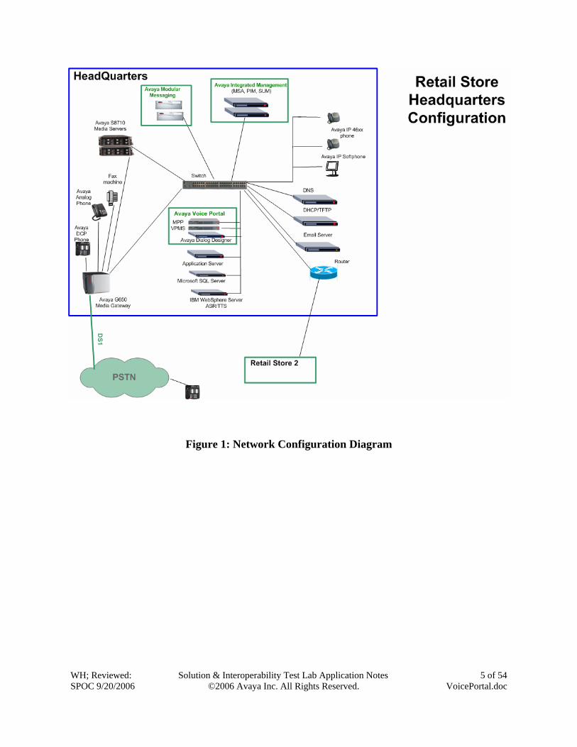
1.2. Test Configuration Figure 1 illustrates the Retail Store Headquarters configuration used to verify these Application Notes. The Headquarters consists of a pair of Avaya S8710 Media Servers with one Avaya G650 Media Gateway. All IP telephones register to Avaya Communication Manager running on the Avaya S8710 Media Servers at the Headquarters. Note: These Application Notes assume that the Retail Store Headquarters depicted in Figure 1 is already in place, as well as Avaya Communication Manager, Avaya Media Gateway, routers,
WH; Reviewed: SPOC 9/20/2006
Solution & Interoperability Test Lab Application Notes ©2006 Avaya Inc. All Rights Reserved.
4 of 54 VoicePortal.doc
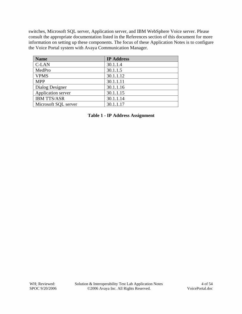
switches, Microsoft SQL server, Application server, and IBM WebSphere Voice server. Please consult the appropriate documentation listed in the References section of this document for more information on setting up these components. The focus of these Application Notes is to configure the Voice Portal system with Avaya Communication Manager.
Name IP Address C-LAN 30.1.1.4 MedPro 30.1.1.5 VPMS 30.1.1.12 MPP 30.1.1.11 Dialog Designer 30.1.1.16 Application server 30.1.1.15 IBM TTS/ASR 30.1.1.14 Microsoft SQL server 30.1.1.17
Table 1 - IP Address Assignment
WH; Reviewed: SPOC 9/20/2006
Solution & Interoperability Test Lab Application Notes ©2006 Avaya Inc. All Rights Reserved.
5 of 54 VoicePortal.doc
Figure 1: Network Configuration Diagram
WH; Reviewed: SPOC 9/20/2006
Solution & Interoperability Test Lab Application Notes ©2006 Avaya Inc. All Rights Reserved.
6 of 54 VoicePortal.doc
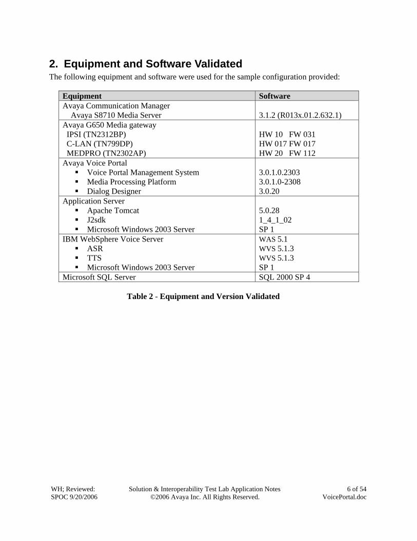
2. Equipment and Software Validated The following equipment and software were used for the sample configuration provided:
Equipment Software Avaya Communication Manager Avaya S8710 Media Server
3.1.2 (R013x.01.2.632.1)
Avaya G650 Media gateway IPSI (TN2312BP) C-LAN (TN799DP) MEDPRO (TN2302AP)
HW 10 FW 031 HW 017 FW 017 HW 20 FW 112
Avaya Voice Portal Voice Portal Management System Media Processing Platform Dialog Designer
3.0.1.0.2303 3.0.1.0-2308 3.0.20
Application Server Apache Tomcat J2sdk Microsoft Windows 2003 Server
5.0.28 1_4_1_02 SP 1
IBM WebSphere Voice Server ASR TTS Microsoft Windows 2003 Server
WAS 5.1 WVS 5.1.3 WVS 5.1.3 SP 1
Microsoft SQL Server SQL 2000 SP 4 Table 2 - Equipment and Version Validated
WH; Reviewed: SPOC 9/20/2006
Solution & Interoperability Test Lab Application Notes ©2006 Avaya Inc. All Rights Reserved.
7 of 54 VoicePortal.doc
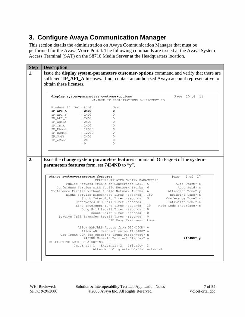
3. Configure Avaya Communication Manager This section details the administration on Avaya Communication Manager that must be performed for the Avaya Voice Portal. The following commands are issued at the Avaya System Access Terminal (SAT) on the S8710 Media Server at the Headquarters location. Step Description 1. Issue the display system-parameters customer-options command and verify that there are
sufficient IP_API_A licenses. If not contact an authorized Avaya account representative to obtain these licenses.
2. Issue the change system-parameters features command. On Page 6 of the system-parameters features form, set 7434ND to “y”.
display system-parameters customer-options Page 10 of 11 MAXIMUM IP REGISTRATIONS BY PRODUCT ID Product ID Rel. Limit Used IP_API_A : 2400 0 IP_API_B : 2400 0 IP_API_C : 2400 0 IP_Agent : 2400 0 IP_IR_A : 2400 0 IP_Phone : 12000 9 IP_ROMax : 12000 0 IP_Soft : 2400 0 IP_eCons : 20 0 : 0 0
change system-parameters features Page 6 of 17 FEATURE-RELATED SYSTEM PARAMETERS Public Network Trunks on Conference Call: 5 Auto Start? n Conference Parties with Public Network Trunks: 6 Auto Hold? n Conference Parties without Public Network Trunks: 6 Attendant Tone? y Night Service Disconnect Timer (seconds): 180 Bridging Tone? n Short Interdigit Timer (seconds): 3 Conference Tone? n Unanswered DID Call Timer (seconds): Intrusion Tone? n Line Intercept Tone Timer (seconds): 30 Mode Code Interface? n Long Hold Recall Timer (seconds): 0 Reset Shift Timer (seconds): 0 Station Call Transfer Recall Timer (seconds): 0 DID Busy Treatment: tone Allow AAR/ARS Access from DID/DIOD? y Allow ANI Restriction on AAR/ARS? n Use Trunk COR for Outgoing Trunk Disconnect? n 7405ND Numeric Terminal Display? n 7434ND? y DISTINCTIVE AUDIBLE ALERTING Internal: 1 External: 2 Priority: 3 Attendant Originated Calls: external
WH; Reviewed: SPOC 9/20/2006
Solution & Interoperability Test Lab Application Notes ©2006 Avaya Inc. All Rights Reserved.
8 of 54 VoicePortal.doc
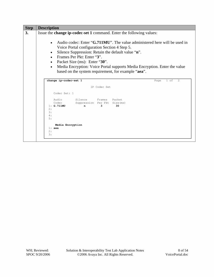
Step Description 3. Issue the change ip-codec-set 1 command. Enter the following values:
• Audio codec: Enter “G.711MU”. The value administered here will be used in
Voice Portal configuration Section 4 Step 5. • Silence Suppression: Retain the default value “n”. • Frames Per Pkt: Enter “3”. • Packet Size (ms): Enter “30”. • Media Encryption: Voice Portal supports Media Encryption. Enter the value
based on the system requirement, for example “aea”.
change ip-codec-set 1 Page 1 of 2 IP Codec Set Codec Set: 1 Audio Silence Frames Packet Codec Suppression Per Pkt Size(ms) 1: G.711MU n 3 30 2: 3: 4: 5: Media Encryption 1: aea 2: 3:
WH; Reviewed: SPOC 9/20/2006
Solution & Interoperability Test Lab Application Notes ©2006 Avaya Inc. All Rights Reserved.
9 of 54 VoicePortal.doc
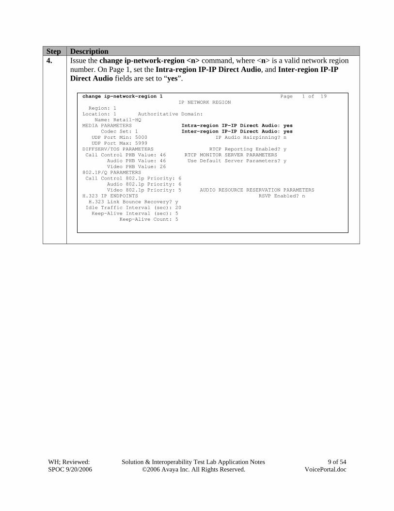
Step Description 4. Issue the change ip-network-region <n> command, where <n> is a valid network region
number. On Page 1, set the Intra-region IP-IP Direct Audio, and Inter-region IP-IP Direct Audio fields are set to “yes”.
change ip-network-region 1 Page 1 of 19 IP NETWORK REGION Region: 1 Location: 1 Authoritative Domain: Name: Retail-HQ MEDIA PARAMETERS Intra-region IP-IP Direct Audio: yes Codec Set: 1 Inter-region IP-IP Direct Audio: yes UDP Port Min: 5000 IP Audio Hairpinning? n UDP Port Max: 5999 DIFFSERV/TOS PARAMETERS RTCP Reporting Enabled? y Call Control PHB Value: 46 RTCP MONITOR SERVER PARAMETERS Audio PHB Value: 46 Use Default Server Parameters? y Video PHB Value: 26 802.1P/Q PARAMETERS Call Control 802.1p Priority: 6 Audio 802.1p Priority: 6 Video 802.1p Priority: 5 AUDIO RESOURCE RESERVATION PARAMETERS H.323 IP ENDPOINTS RSVP Enabled? n H.323 Link Bounce Recovery? y Idle Traffic Interval (sec): 20 Keep-Alive Interval (sec): 5 Keep-Alive Count: 5

WH; Reviewed: SPOC 9/20/2006
Solution & Interoperability Test Lab Application Notes ©2006 Avaya Inc. All Rights Reserved.
10 of 54 VoicePortal.doc
Step Description 5. Issue the add station <n> command, where <n> is a valid unused station number, for
example 2220011. The station numbers correspond to the stations assigned to the VP ports and will be used later in Section 4 Step 4. On Page 1, enter the following values:
• Type: Enter station type “7434ND”. • Port: Enter “IP”. • Name: Enter a descriptive name. • Security Code: Enter a valid station security code. • Display Module: Enter “y”. • Display Language: Enter “english”. • IP Softphone: Enter “y”.
add station 2220011 Page 1 of 5 STATION Extension: 2220011 Lock Messages? n BCC: 0 Type: 7434ND Security Code: * TN: 1 Port: IP Coverage Path 1: COR: 1 Name: Voice Portal 1 Coverage Path 2: COS: 1 Hunt-to Station: STATION OPTIONS Loss Group: 2 Personalized Ringing Pattern: 1 Data Module? n Message Lamp Ext: 2220011 Display Module? y Display Language: english Coverage Module? n Media Complex Ext: IP SoftPhone? y IP Video Softphone? n
WH; Reviewed: SPOC 9/20/2006
Solution & Interoperability Test Lab Application Notes ©2006 Avaya Inc. All Rights Reserved.
11 of 54 VoicePortal.doc
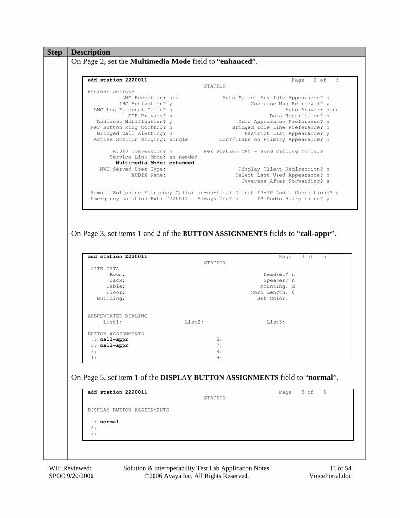
Step Description On Page 2, set the Multimedia Mode field to “enhanced”.
On Page 3, set items 1 and 2 of the BUTTON ASSIGNMENTS fields to “call-appr”.
On Page 5, set item 1 of the DISPLAY BUTTON ASSIGNMENTS field to “normal”.
add station 2220011 Page 3 of 5 STATION SITE DATA Room: Headset? n Jack: Speaker? n Cable: Mounting: d Floor: Cord Length: 0 Building: Set Color: ABBREVIATED DIALING List1: List2: List3: BUTTON ASSIGNMENTS 1: call-appr 6: 2: call-appr 7: 3: 8: 4: 9:
add station 2220011 Page 2 of 5 STATION FEATURE OPTIONS LWC Reception: spe Auto Select Any Idle Appearance? n LWC Activation? y Coverage Msg Retrieval? y LWC Log External Calls? n Auto Answer: none CDR Privacy? n Data Restriction? n Redirect Notification? y Idle Appearance Preference? n Per Button Ring Control? n Bridged Idle Line Preference? n Bridged Call Alerting? n Restrict Last Appearance? y Active Station Ringing: single Conf/Trans on Primary Appearance? n H.320 Conversion? n Per Station CPN - Send Calling Number? Service Link Mode: as-needed Multimedia Mode: enhanced MWI Served User Type: Display Client Redirection? n AUDIX Name: Select Last Used Appearance? n Coverage After Forwarding? s Remote Softphone Emergency Calls: as-on-local Direct IP-IP Audio Connections? y Emergency Location Ext: 2220011 Always Use? n IP Audio Hairpinning? y
add station 2220011 Page 5 of 5 STATION DISPLAY BUTTON ASSIGNMENTS 1: normal 2: 3:
WH; Reviewed: SPOC 9/20/2006
Solution & Interoperability Test Lab Application Notes ©2006 Avaya Inc. All Rights Reserved.
12 of 54 VoicePortal.doc
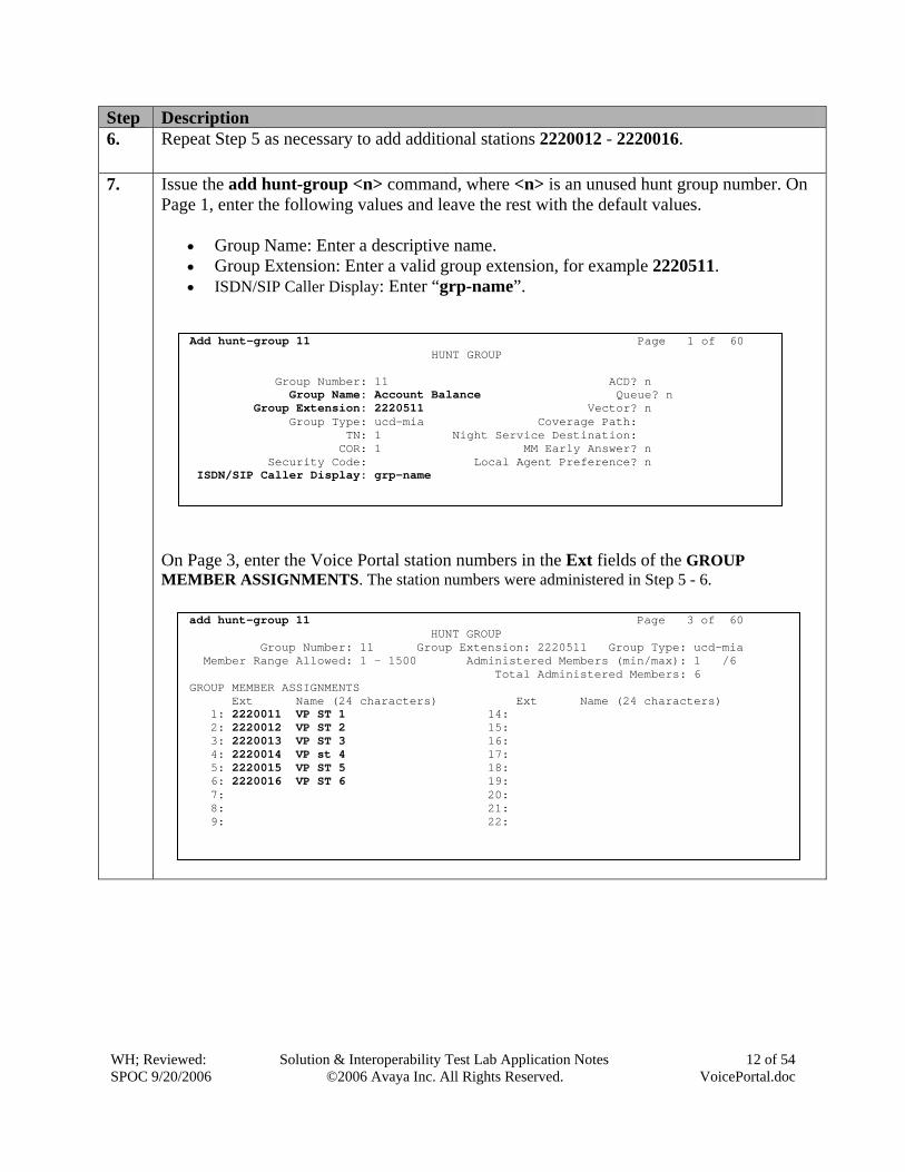
Step Description 6. Repeat Step 5 as necessary to add additional stations 2220012 - 2220016.
7. Issue the add hunt-group <n> command, where <n> is an unused hunt group number. On Page 1, enter the following values and leave the rest with the default values.
• Group Name: Enter a descriptive name. • Group Extension: Enter a valid group extension, for example 2220511. • ISDN/SIP Caller Display: Enter “grp-name”.
On Page 3, enter the Voice Portal station numbers in the Ext fields of the GROUP MEMBER ASSIGNMENTS. The station numbers were administered in Step 5 - 6.
Add hunt-group 11 Page 1 of 60 HUNT GROUP Group Number: 11 ACD? n Group Name: Account Balance Queue? n Group Extension: 2220511 Vector? n Group Type: ucd-mia Coverage Path: TN: 1 Night Service Destination: COR: 1 MM Early Answer? n Security Code: Local Agent Preference? n ISDN/SIP Caller Display: grp-name
add hunt-group 11 Page 3 of 60 HUNT GROUP Group Number: 11 Group Extension: 2220511 Group Type: ucd-mia Member Range Allowed: 1 - 1500 Administered Members (min/max): 1 /6 Total Administered Members: 6 GROUP MEMBER ASSIGNMENTS Ext Name (24 characters) Ext Name (24 characters) 1: 2220011 VP ST 1 14: 2: 2220012 VP ST 2 15: 3: 2220013 VP ST 3 16: 4: 2220014 VP st 4 17: 5: 2220015 VP ST 5 18: 6: 2220016 VP ST 6 19: 7: 20: 8: 21: 9: 22:
WH; Reviewed: SPOC 9/20/2006
Solution & Interoperability Test Lab Application Notes ©2006 Avaya Inc. All Rights Reserved.
13 of 54 VoicePortal.doc
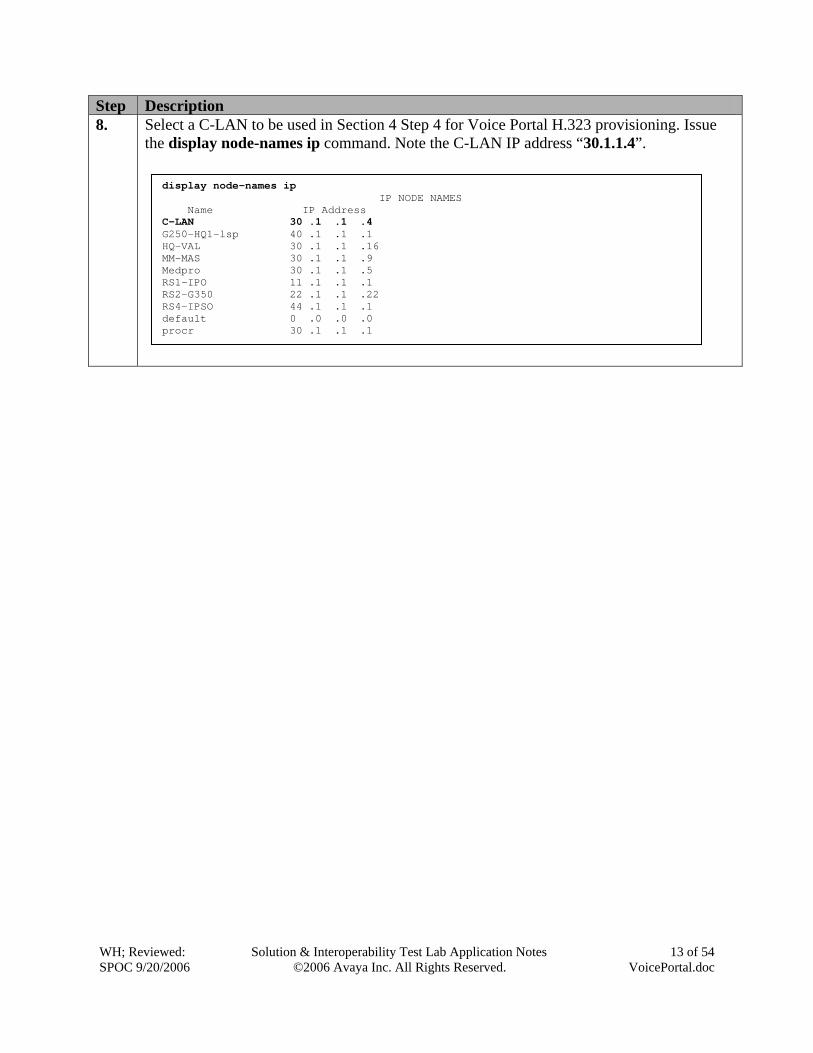
Step Description 8. Select a C-LAN to be used in Section 4 Step 4 for Voice Portal H.323 provisioning. Issue
the display node-names ip command. Note the C-LAN IP address “30.1.1.4”.
display node-names ip IP NODE NAMES Name IP Address C-LAN 30 .1 .1 .4 G250-HQ1-lsp 40 .1 .1 .1 HQ-VAL 30 .1 .1 .16 MM-MAS 30 .1 .1 .9 Medpro 30 .1 .1 .5 RS1-IPO 11 .1 .1 .1 RS2-G350 22 .1 .1 .22 RS4-IPSO 44 .1 .1 .1 default 0 .0 .0 .0 procr 30 .1 .1 .1
WH; Reviewed: SPOC 9/20/2006
Solution & Interoperability Test Lab Application Notes ©2006 Avaya Inc. All Rights Reserved.
14 of 54 VoicePortal.doc
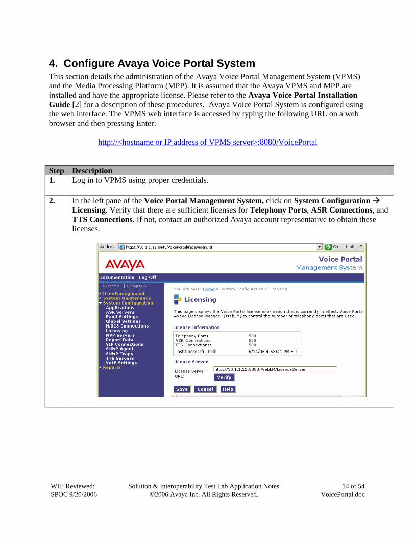
4. Configure Avaya Voice Portal System This section details the administration of the Avaya Voice Portal Management System (VPMS) and the Media Processing Platform (MPP). It is assumed that the Avaya VPMS and MPP are installed and have the appropriate license. Please refer to the Avaya Voice Portal Installation Guide [2] for a description of these procedures. Avaya Voice Portal System is configured using the web interface. The VPMS web interface is accessed by typing the following URL on a web browser and then pressing Enter:
http://<hostname or IP address of VPMS server>:8080/VoicePortal Step Description 1. Log in to VPMS using proper credentials.
2. In the left pane of the Voice Portal Management System, click on System Configuration
Licensing. Verify that there are sufficient licenses for Telephony Ports, ASR Connections, and TTS Connections. If not, contact an authorized Avaya account representative to obtain these licenses.
WH; Reviewed: SPOC 9/20/2006
Solution & Interoperability Test Lab Application Notes ©2006 Avaya Inc. All Rights Reserved.
15 of 54 VoicePortal.doc
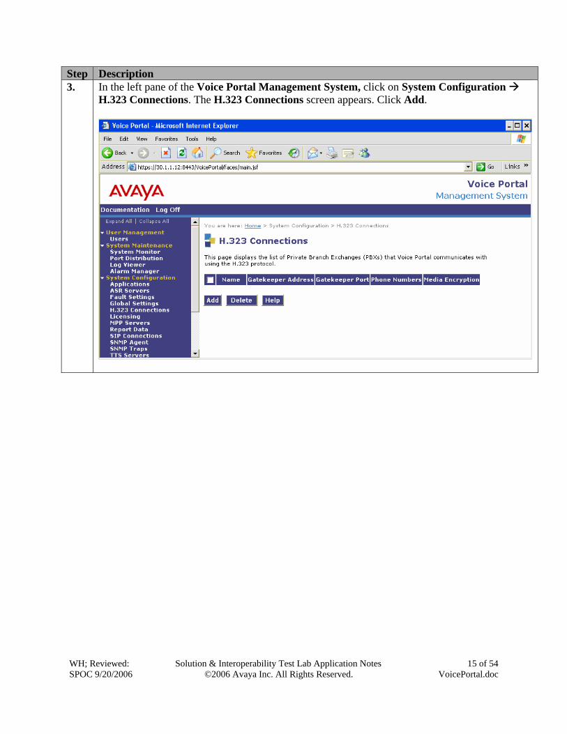
Step Description 3. In the left pane of the Voice Portal Management System, click on System Configuration
H.323 Connections. The H.323 Connections screen appears. Click Add.
WH; Reviewed: SPOC 9/20/2006
Solution & Interoperability Test Lab Application Notes ©2006 Avaya Inc. All Rights Reserved.
16 of 54 VoicePortal.doc
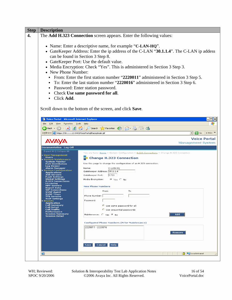
Step Description 4. The Add H.323 Connection screen appears. Enter the following values:
• Name: Enter a descriptive name, for example “C-LAN-HQ”. • GateKeeper Address: Enter the ip address of the C-LAN “30.1.1.4”. The C-LAN ip addess
can be found in Section 3 Step 8. • GateKeeper Port: Use the default value. • Media Encryption: Check “Yes”. This is administered in Section 3 Step 3. • New Phone Number:
From: Enter the first station number “2220011” administered in Section 3 Step 5. To: Enter the last station number “2220016” administered in Section 3 Step 6. Password: Enter station password. Check Use same password for all. Click Add.
Scroll down to the bottom of the screen, and click Save.
WH; Reviewed: SPOC 9/20/2006
Solution & Interoperability Test Lab Application Notes ©2006 Avaya Inc. All Rights Reserved.
17 of 54 VoicePortal.doc
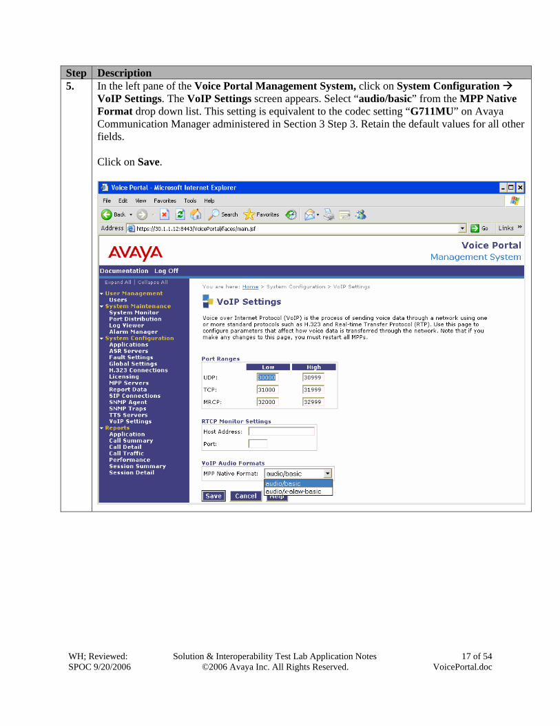
Step Description 5. In the left pane of the Voice Portal Management System, click on System Configuration
VoIP Settings. The VoIP Settings screen appears. Select “audio/basic” from the MPP Native Format drop down list. This setting is equivalent to the codec setting “G711MU” on Avaya Communication Manager administered in Section 3 Step 3. Retain the default values for all other fields. Click on Save.
WH; Reviewed: SPOC 9/20/2006
Solution & Interoperability Test Lab Application Notes ©2006 Avaya Inc. All Rights Reserved.
18 of 54 VoicePortal.doc
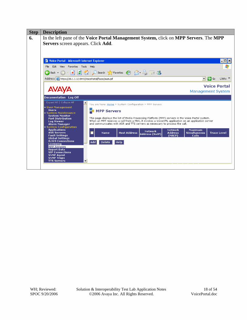
Step Description 6. In the left pane of the Voice Portal Management System, click on MPP Servers. The MPP
Servers screen appears. Click Add.
WH; Reviewed: SPOC 9/20/2006
Solution & Interoperability Test Lab Application Notes ©2006 Avaya Inc. All Rights Reserved.
19 of 54 VoicePortal.doc
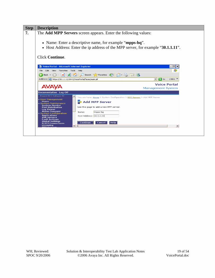
Step Description 7. The Add MPP Servers screen appears. Enter the following values:
• Name: Enter a descriptive name, for example “mpps-hq”. • Host Address: Enter the ip address of the MPP server, for example “30.1.1.11”.
Click Continue.
WH; Reviewed: SPOC 9/20/2006
Solution & Interoperability Test Lab Application Notes ©2006 Avaya Inc. All Rights Reserved.
20 of 54 VoicePortal.doc
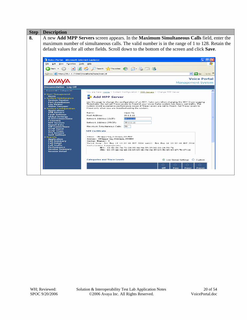
Step Description 8. A new Add MPP Servers screen appears. In the Maximum Simultaneous Calls field, enter the
maximum number of simultaneous calls. The valid number is in the range of 1 to 128. Retain the default values for all other fields. Scroll down to the bottom of the screen and click Save.
WH; Reviewed: SPOC 9/20/2006
Solution & Interoperability Test Lab Application Notes ©2006 Avaya Inc. All Rights Reserved.
21 of 54 VoicePortal.doc
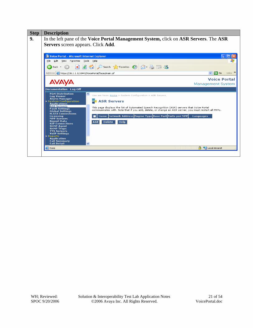
Step Description 9. In the left pane of the Voice Portal Management System, click on ASR Servers. The ASR
Servers screen appears. Click Add.
WH; Reviewed: SPOC 9/20/2006
Solution & Interoperability Test Lab Application Notes ©2006 Avaya Inc. All Rights Reserved.
22 of 54 VoicePortal.doc
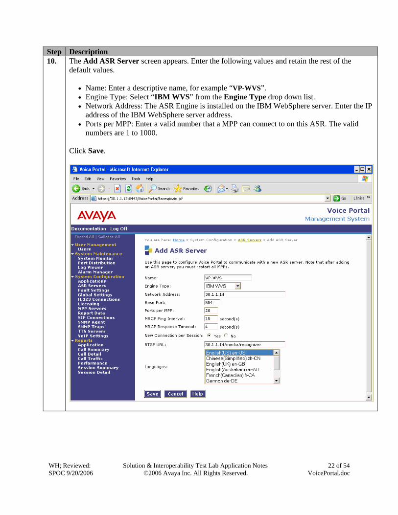
Step Description 10. The Add ASR Server screen appears. Enter the following values and retain the rest of the
default values.
• Name: Enter a descriptive name, for example “VP-WVS”. • Engine Type: Select “IBM WVS” from the Engine Type drop down list. • Network Address: The ASR Engine is installed on the IBM WebSphere server. Enter the IP
address of the IBM WebSphere server address. • Ports per MPP: Enter a valid number that a MPP can connect to on this ASR. The valid
numbers are 1 to 1000. Click Save.
WH; Reviewed: SPOC 9/20/2006
Solution & Interoperability Test Lab Application Notes ©2006 Avaya Inc. All Rights Reserved.
23 of 54 VoicePortal.doc
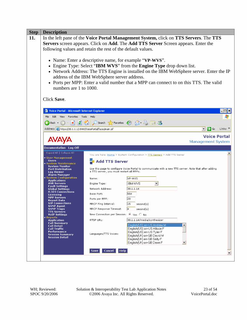
Step Description 11. In the left pane of the Voice Portal Management System, click on TTS Servers. The TTS
Servers screen appears. Click on Add. The Add TTS Server Screen appears. Enter the following values and retain the rest of the default values.
• Name: Enter a descriptive name, for example “VP-WVS”. • Engine Type: Select “IBM WVS” from the Engine Type drop down list. • Network Address: The TTS Engine is installed on the IBM WebSphere server. Enter the IP
address of the IBM WebSphere server address. • Ports per MPP: Enter a valid number that a MPP can connect to on this TTS. The valid
numbers are 1 to 1000. Click Save.
WH; Reviewed: SPOC 9/20/2006
Solution & Interoperability Test Lab Application Notes ©2006 Avaya Inc. All Rights Reserved.
24 of 54 VoicePortal.doc
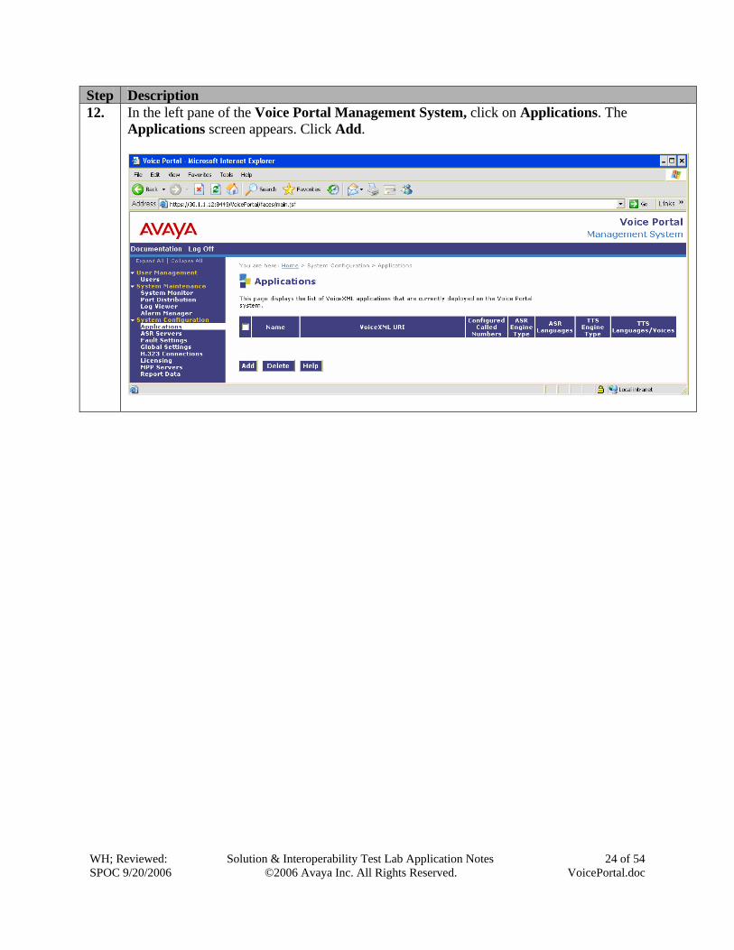
Step Description 12. In the left pane of the Voice Portal Management System, click on Applications. The
Applications screen appears. Click Add.
WH; Reviewed: SPOC 9/20/2006
Solution & Interoperability Test Lab Application Notes ©2006 Avaya Inc. All Rights Reserved.
25 of 54 VoicePortal.doc
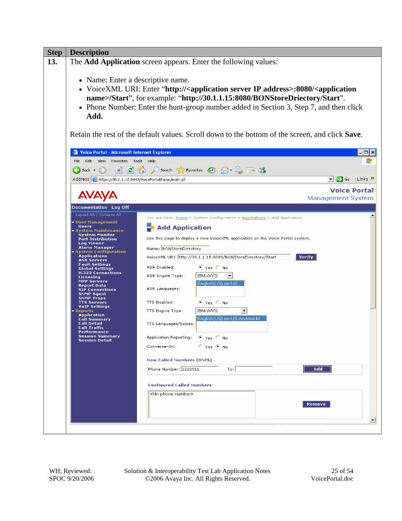
Step Description 13. The Add Application screen appears. Enter the following values:
• Name: Enter a descriptive name. • VoiceXML URI: Enter “http://<application server IP address>:8080/<application
name>/Start”, for example: “http://30.1.1.15:8080/BONStoreDriectory/Start”. • Phone Number: Enter the hunt-group number added in Section 3, Step 7, and then click
Add. Retain the rest of the default values. Scroll down to the bottom of the screen, and click Save.
WH; Reviewed: SPOC 9/20/2006
Solution & Interoperability Test Lab Application Notes ©2006 Avaya Inc. All Rights Reserved.
26 of 54 VoicePortal.doc
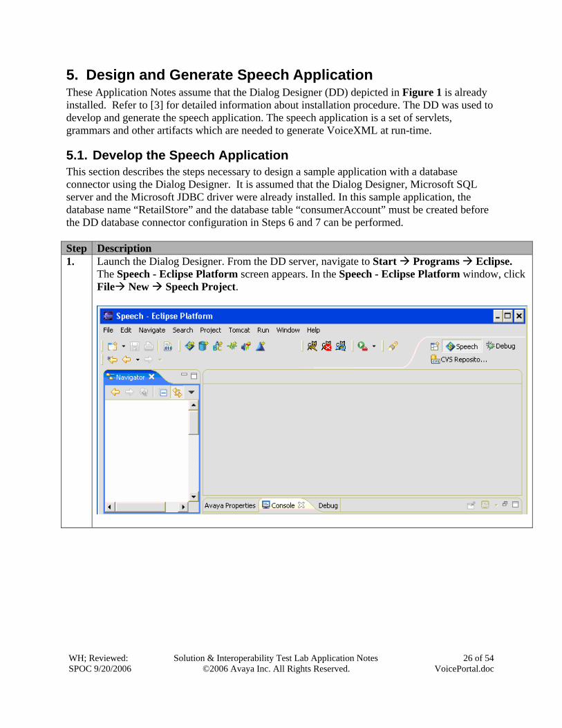
5. Design and Generate Speech Application These Application Notes assume that the Dialog Designer (DD) depicted in Figure 1 is already installed. Refer to [3] for detailed information about installation procedure. The DD was used to develop and generate the speech application. The speech application is a set of servlets, grammars and other artifacts which are needed to generate VoiceXML at run-time.
5.1. Develop the Speech Application This section describes the steps necessary to design a sample application with a database connector using the Dialog Designer. It is assumed that the Dialog Designer, Microsoft SQL server and the Microsoft JDBC driver were already installed. In this sample application, the database name “RetailStore” and the database table “consumerAccount” must be created before the DD database connector configuration in Steps 6 and 7 can be performed. Step Description 1. Launch the Dialog Designer. From the DD server, navigate to Start Programs Eclipse.
The Speech - Eclipse Platform screen appears. In the Speech - Eclipse Platform window, click File New Speech Project.
WH; Reviewed: SPOC 9/20/2006
Solution & Interoperability Test Lab Application Notes ©2006 Avaya Inc. All Rights Reserved.
27 of 54 VoicePortal.doc
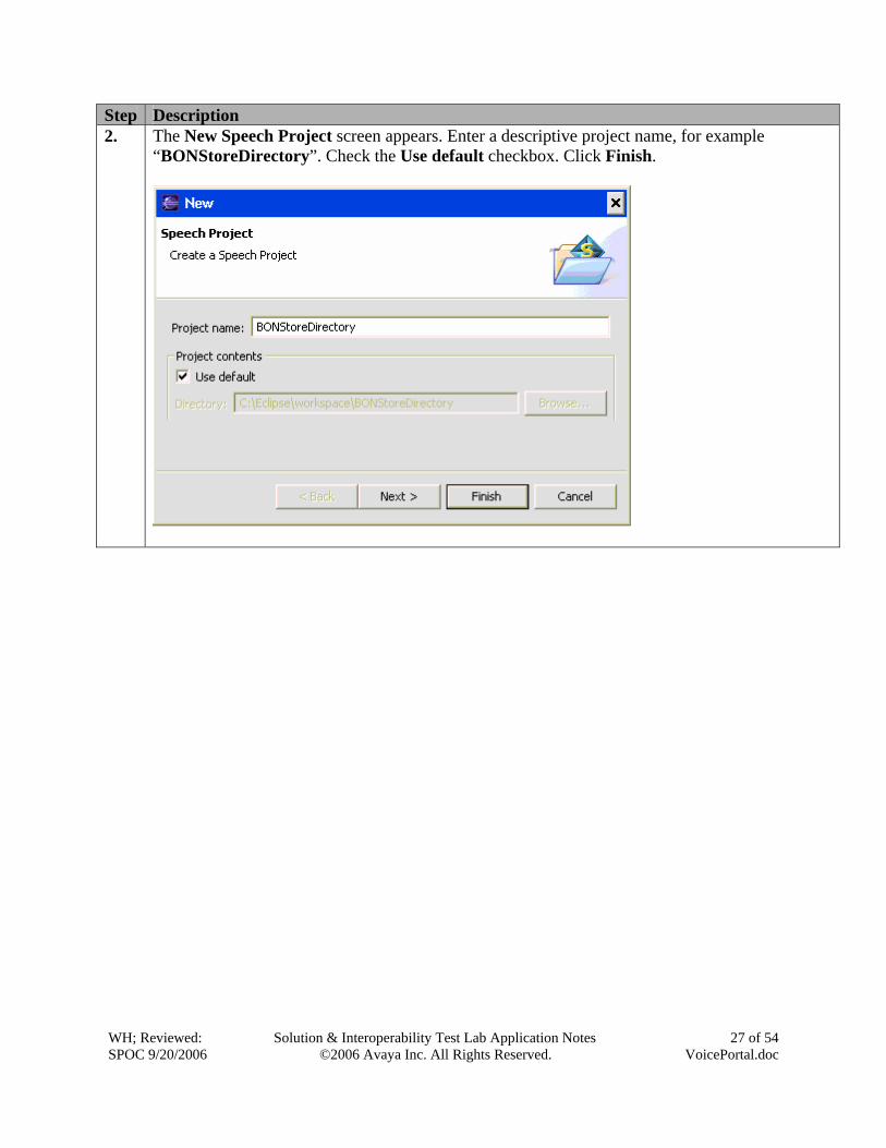
Step Description 2. The New Speech Project screen appears. Enter a descriptive project name, for example
“BONStoreDirectory”. Check the Use default checkbox. Click Finish.
WH; Reviewed: SPOC 9/20/2006
Solution & Interoperability Test Lab Application Notes ©2006 Avaya Inc. All Rights Reserved.
28 of 54 VoicePortal.doc
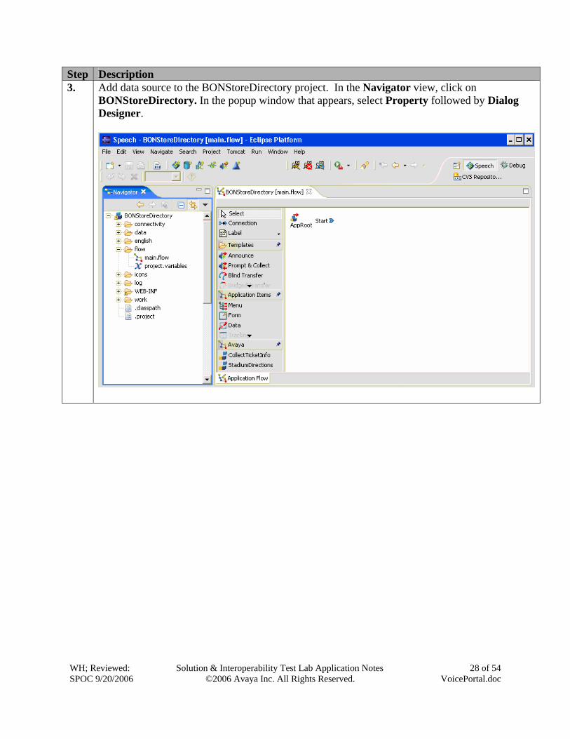
Step Description 3. Add data source to the BONStoreDirectory project. In the Navigator view, click on
BONStoreDirectory. In the popup window that appears, select Property followed by Dialog Designer.
WH; Reviewed: SPOC 9/20/2006
Solution & Interoperability Test Lab Application Notes ©2006 Avaya Inc. All Rights Reserved.
29 of 54 VoicePortal.doc
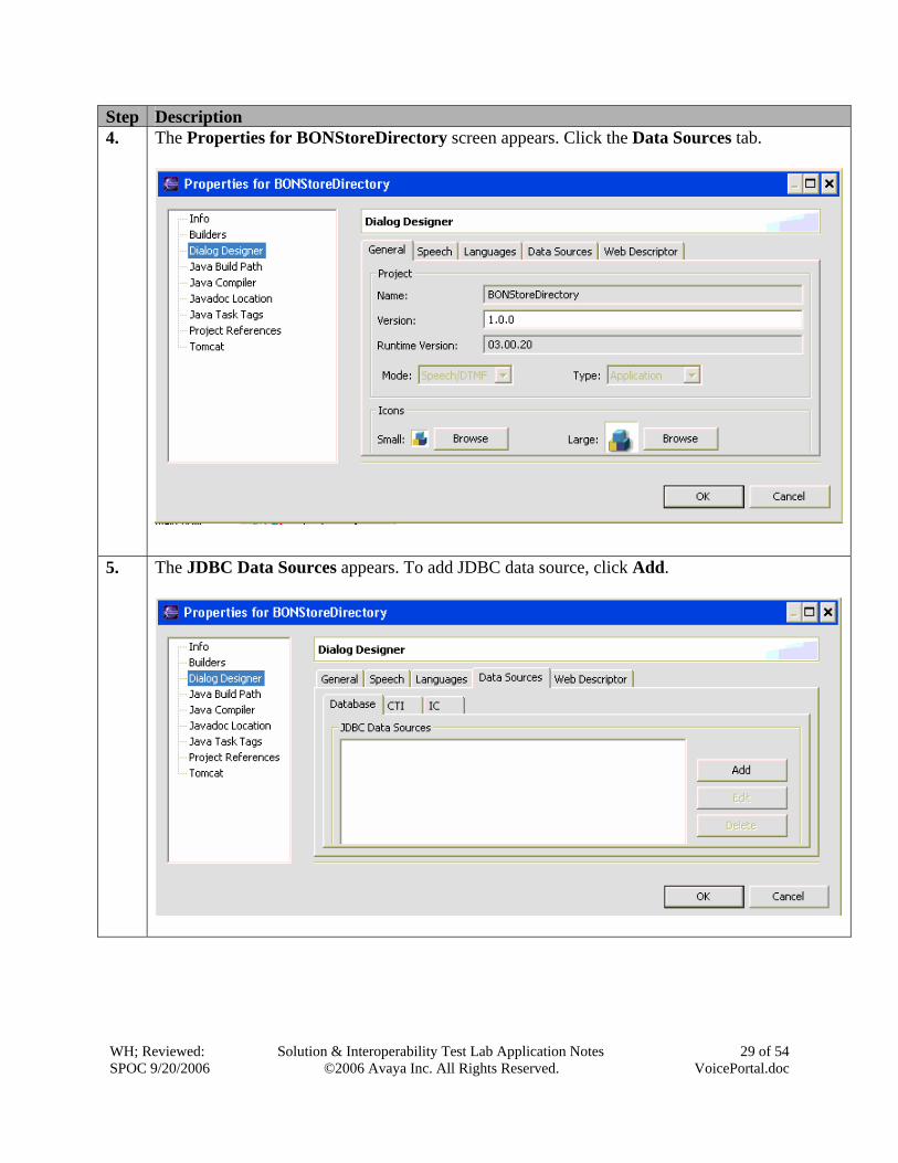
Step Description 4. The Properties for BONStoreDirectory screen appears. Click the Data Sources tab.
5. The JDBC Data Sources appears. To add JDBC data source, click Add.
WH; Reviewed: SPOC 9/20/2006
Solution & Interoperability Test Lab Application Notes ©2006 Avaya Inc. All Rights Reserved.
30 of 54 VoicePortal.doc
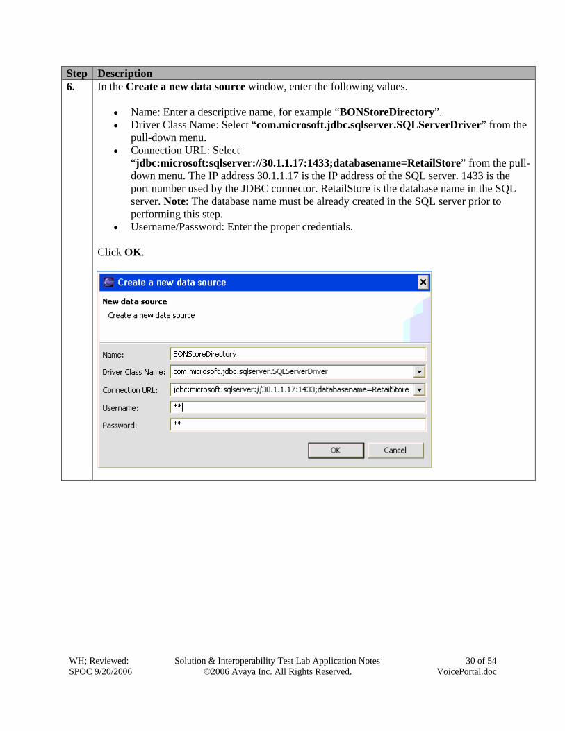
Step Description 6. In the Create a new data source window, enter the following values.
• Name: Enter a descriptive name, for example “BONStoreDirectory”. • Driver Class Name: Select “com.microsoft.jdbc.sqlserver.SQLServerDriver” from the
pull-down menu. • Connection URL: Select
“jdbc:microsoft:sqlserver://30.1.1.17:1433;databasename=RetailStore” from the pull-down menu. The IP address 30.1.1.17 is the IP address of the SQL server. 1433 is the port number used by the JDBC connector. RetailStore is the database name in the SQL server. Note: The database name must be already created in the SQL server prior to performing this step.
• Username/Password: Enter the proper credentials.
Click OK.
WH; Reviewed: SPOC 9/20/2006
Solution & Interoperability Test Lab Application Notes ©2006 Avaya Inc. All Rights Reserved.
31 of 54 VoicePortal.doc
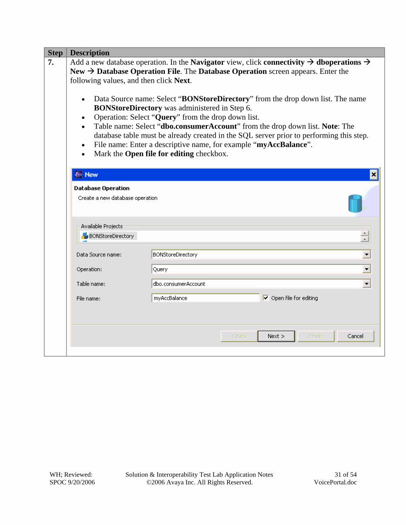
Step Description 7. Add a new database operation. In the Navigator view, click connectivity dboperations
New Database Operation File. The Database Operation screen appears. Enter the following values, and then click Next.
• Data Source name: Select “BONStoreDirectory” from the drop down list. The name BONStoreDirectory was administered in Step 6.
• Operation: Select “Query” from the drop down list. • Table name: Select “dbo.consumerAccount” from the drop down list. Note: The
database table must be already created in the SQL server prior to performing this step. • File name: Enter a descriptive name, for example “myAccBalance”. • Mark the Open file for editing checkbox.
WH; Reviewed: SPOC 9/20/2006
Solution & Interoperability Test Lab Application Notes ©2006 Avaya Inc. All Rights Reserved.
32 of 54 VoicePortal.doc
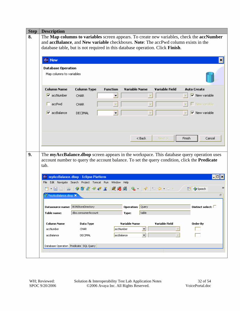
Step Description 8. The Map columns to variables screen appears. To create new variables, check the accNumber
and accBalance, and New variable checkboxes. Note: The accPwd column exists in the database table, but is not required in this database operation. Click Finish.
9. The myAccBalance.dbop screen appears in the workspace. This database query operation uses account number to query the account balance. To set the query condition, click the Predicate tab.
WH; Reviewed: SPOC 9/20/2006
Solution & Interoperability Test Lab Application Notes ©2006 Avaya Inc. All Rights Reserved.
33 of 54 VoicePortal.doc
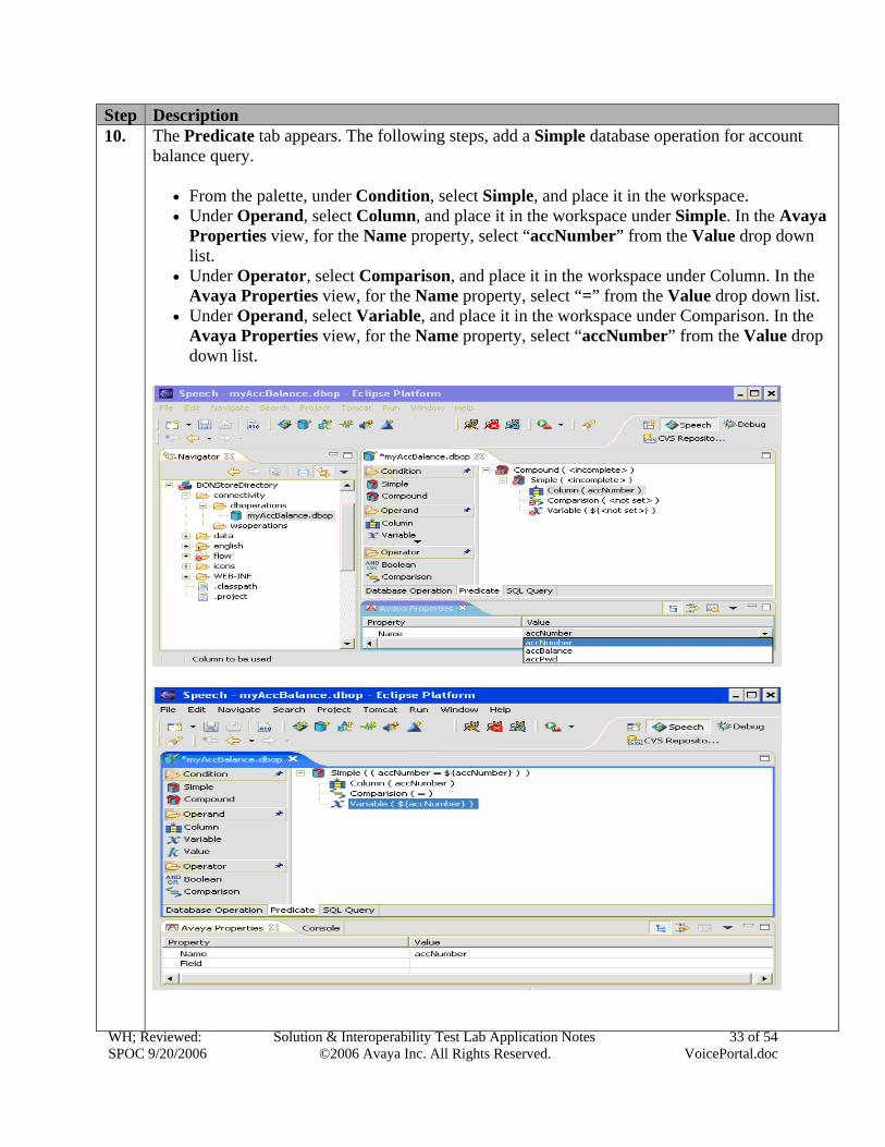
Step Description 10. The Predicate tab appears. The following steps, add a Simple database operation for account
balance query.
• From the palette, under Condition, select Simple, and place it in the workspace. • Under Operand, select Column, and place it in the workspace under Simple. In the Avaya
Properties view, for the Name property, select “accNumber” from the Value drop down list.
• Under Operator, select Comparison, and place it in the workspace under Column. In the Avaya Properties view, for the Name property, select “=” from the Value drop down list.
• Under Operand, select Variable, and place it in the workspace under Comparison. In the Avaya Properties view, for the Name property, select “accNumber” from the Value drop down list.
WH; Reviewed: SPOC 9/20/2006
Solution & Interoperability Test Lab Application Notes ©2006 Avaya Inc. All Rights Reserved.
34 of 54 VoicePortal.doc
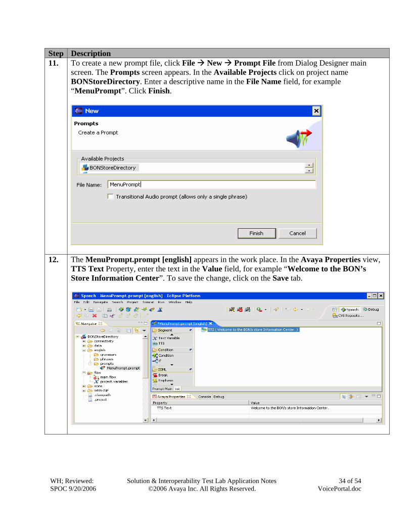
Step Description 11. To create a new prompt file, click File New Prompt File from Dialog Designer main
screen. The Prompts screen appears. In the Available Projects click on project name BONStoreDirectory. Enter a descriptive name in the File Name field, for example “MenuPrompt”. Click Finish.
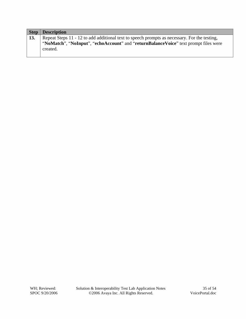
12. The MenuPrompt.prompt [english] appears in the work place. In the Avaya Properties view, TTS Text Property, enter the text in the Value field, for example “Welcome to the BON’s Store Information Center”. To save the change, click on the Save tab.
WH; Reviewed: SPOC 9/20/2006
Solution & Interoperability Test Lab Application Notes ©2006 Avaya Inc. All Rights Reserved.
35 of 54 VoicePortal.doc
Step Description 13. Repeat Steps 11 - 12 to add additional text to speech prompts as necessary. For the testing,
“NoMatch”, “NoInput”, “echoAccount” and “returnBalanceVoice” text prompt files were created.
WH; Reviewed: SPOC 9/20/2006
Solution & Interoperability Test Lab Application Notes ©2006 Avaya Inc. All Rights Reserved.
36 of 54 VoicePortal.doc
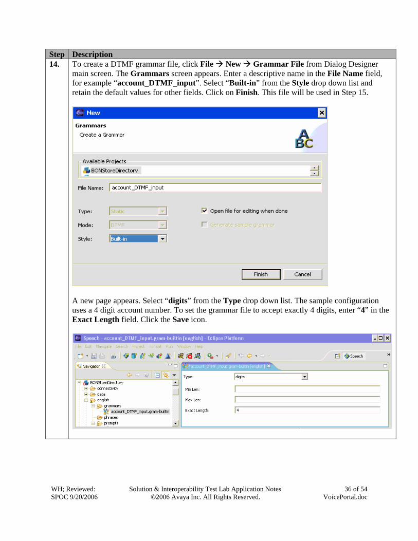
Step Description 14. To create a DTMF grammar file, click File New Grammar File from Dialog Designer
main screen. The Grammars screen appears. Enter a descriptive name in the File Name field, for example “account_DTMF_input”. Select “Built-in” from the Style drop down list and retain the default values for other fields. Click on Finish. This file will be used in Step 15.
A new page appears. Select “digits” from the Type drop down list. The sample configuration uses a 4 digit account number. To set the grammar file to accept exactly 4 digits, enter “4” in the Exact Length field. Click the Save icon.
WH; Reviewed: SPOC 9/20/2006
Solution & Interoperability Test Lab Application Notes ©2006 Avaya Inc. All Rights Reserved.
37 of 54 VoicePortal.doc
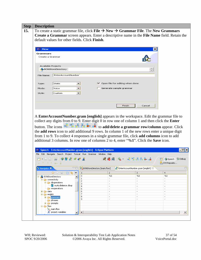
Step Description 15. To create a static grammar file, click File New Grammar File. The New Grammars
Create a Grammar screen appears. Enter a descriptive name in the File Name field. Retain the default values for other fields. Click Finish.
A EnterAccountNumber.gram [english] appears in the workspace. Edit the grammar file to collect any digits from 0 to 9. Enter digit 0 in row one of column 1 and then click the Enter button. The icons to add/delete a grammar row/column appear. Click the add rows icon to add additional 9 rows. In column 1 of the new rows enter a unique digit from 1 to 9. To collect 4 responses in a single grammar file, click add columns icon to add additional 3 columns. In row one of columns 2 to 4, enter “%1”. Click the Save icon.
WH; Reviewed: SPOC 9/20/2006
Solution & Interoperability Test Lab Application Notes ©2006 Avaya Inc. All Rights Reserved.
38 of 54 VoicePortal.doc
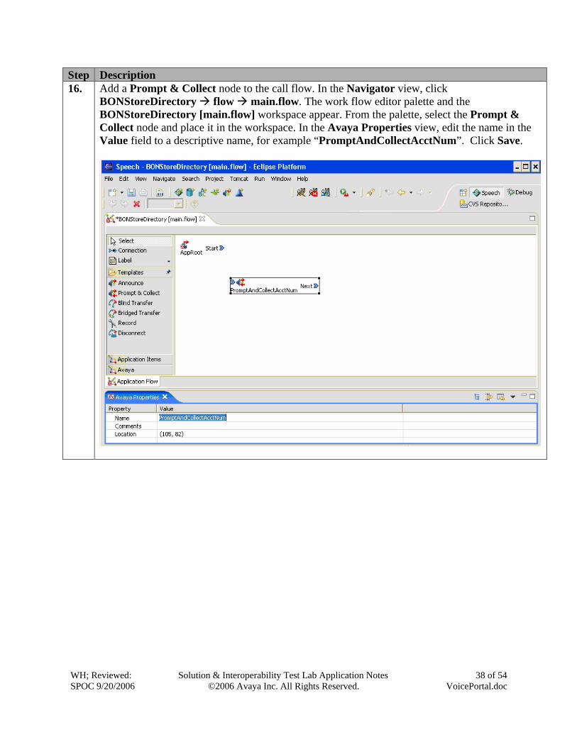
Step Description 16. Add a Prompt & Collect node to the call flow. In the Navigator view, click
BONStoreDirectory flow main.flow. The work flow editor palette and the BONStoreDirectory [main.flow] workspace appear. From the palette, select the Prompt & Collect node and place it in the workspace. In the Avaya Properties view, edit the name in the Value field to a descriptive name, for example “PromptAndCollectAcctNum”. Click Save.
WH; Reviewed: SPOC 9/20/2006
Solution & Interoperability Test Lab Application Notes ©2006 Avaya Inc. All Rights Reserved.
39 of 54 VoicePortal.doc
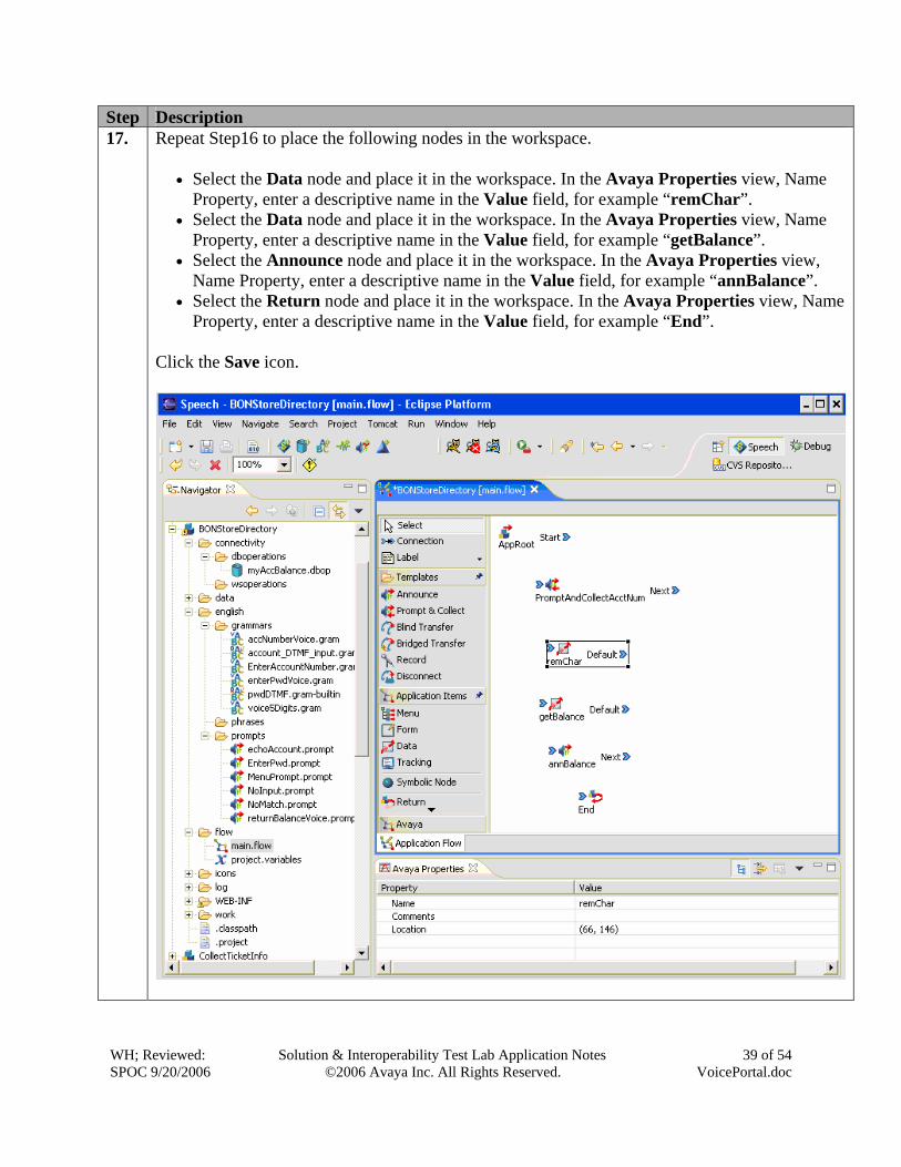
Step Description 17. Repeat Step16 to place the following nodes in the workspace.
• Select the Data node and place it in the workspace. In the Avaya Properties view, Name
Property, enter a descriptive name in the Value field, for example “remChar”. • Select the Data node and place it in the workspace. In the Avaya Properties view, Name
Property, enter a descriptive name in the Value field, for example “getBalance”. • Select the Announce node and place it in the workspace. In the Avaya Properties view,
Name Property, enter a descriptive name in the Value field, for example “annBalance”. • Select the Return node and place it in the workspace. In the Avaya Properties view, Name
Property, enter a descriptive name in the Value field, for example “End”. Click the Save icon.
WH; Reviewed: SPOC 9/20/2006
Solution & Interoperability Test Lab Application Notes ©2006 Avaya Inc. All Rights Reserved.
40 of 54 VoicePortal.doc
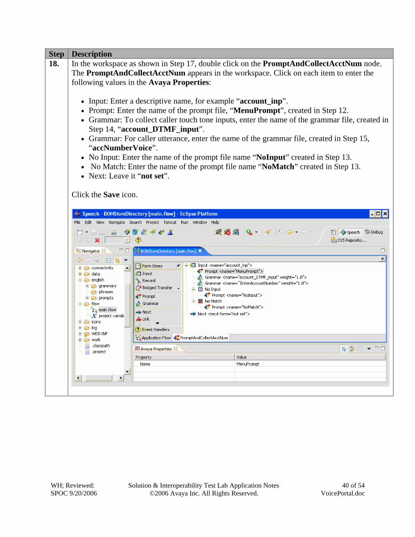
Step Description 18. In the workspace as shown in Step 17, double click on the PromptAndCollectAcctNum node.
The PromptAndCollectAcctNum appears in the workspace. Click on each item to enter the following values in the Avaya Properties:
• Input: Enter a descriptive name, for example “account_inp”. • Prompt: Enter the name of the prompt file, “MenuPrompt”, created in Step 12. • Grammar: To collect caller touch tone inputs, enter the name of the grammar file, created in
Step 14, “account_DTMF_input”. • Grammar: For caller utterance, enter the name of the grammar file, created in Step 15,
“accNumberVoice”. • No Input: Enter the name of the prompt file name “NoInput” created in Step 13. • No Match: Enter the name of the prompt file name “NoMatch” created in Step 13. • Next: Leave it “not set”.
Click the Save icon.
WH; Reviewed: SPOC 9/20/2006
Solution & Interoperability Test Lab Application Notes ©2006 Avaya Inc. All Rights Reserved.
41 of 54 VoicePortal.doc
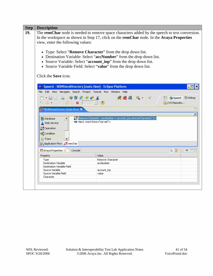
Step Description 19. The remChar node is needed to remove space characters added by the speech to text conversion.
In the workspace as shown in Step 17, click on the remChar node. In the Avaya Properties view, enter the following values:
• Type: Select “Remove Character” from the drop down list. • Destination Variable: Select “accNumber” from the drop down list. • Source Variable: Select “account_inp” from the drop down list. • Source Variable Field: Select “value” from the drop down list.
Click the Save icon.
WH; Reviewed: SPOC 9/20/2006
Solution & Interoperability Test Lab Application Notes ©2006 Avaya Inc. All Rights Reserved.
42 of 54 VoicePortal.doc
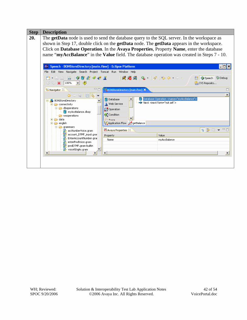
Step Description 20. The getData node is used to send the database query to the SQL server. In the workspace as
shown in Step 17, double click on the getData node. The getData appears in the workspace. Click on Database Operation. In the Avaya Properties, Property Name, enter the database name “myAccBalance” in the Value field. The database operation was created in Steps 7 - 10.
WH; Reviewed: SPOC 9/20/2006
Solution & Interoperability Test Lab Application Notes ©2006 Avaya Inc. All Rights Reserved.
43 of 54 VoicePortal.doc
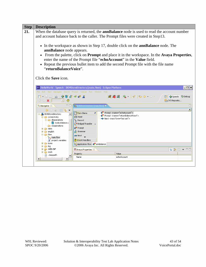
Step Description 21. When the database query is returned, the annBalance node is used to read the account number
and account balance back to the caller. The Prompt files were created in Step13.
• In the workspace as shown in Step 17, double click on the annBalance node. The annBalance node appears.
• From the palette, click on Prompt and place it in the workspace. In the Avaya Properties, enter the name of the Prompt file “echoAccount” in the Value field.
• Repeat the previous bullet item to add the second Prompt file with the file name “returnBalanceVoice”.
Click the Save icon.
WH; Reviewed: SPOC 9/20/2006
Solution & Interoperability Test Lab Application Notes ©2006 Avaya Inc. All Rights Reserved.
44 of 54 VoicePortal.doc
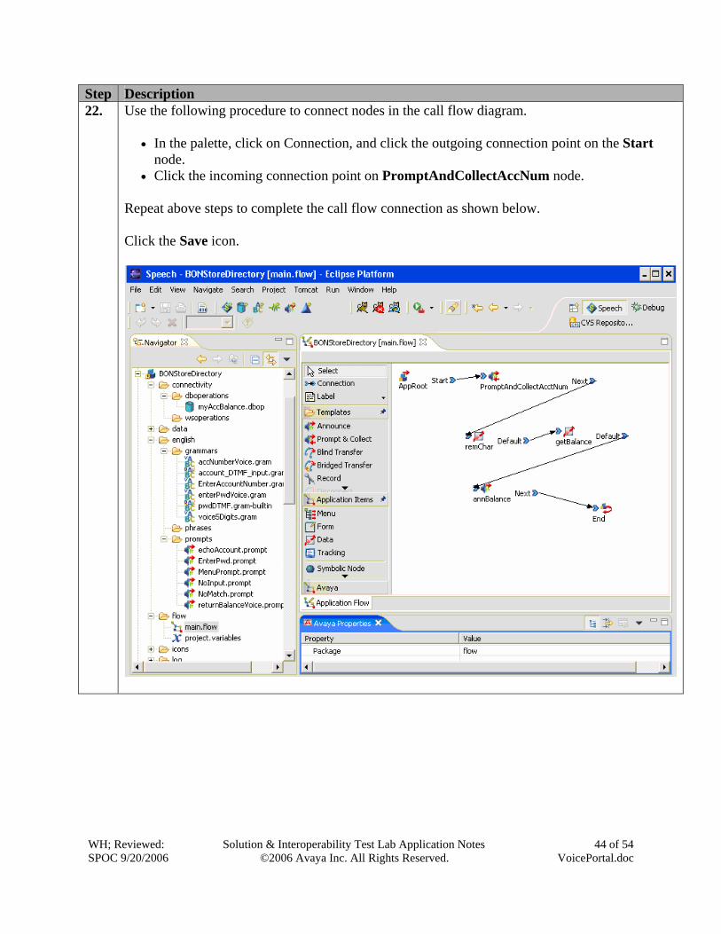
Step Description 22. Use the following procedure to connect nodes in the call flow diagram.
• In the palette, click on Connection, and click the outgoing connection point on the Start
node. • Click the incoming connection point on PromptAndCollectAccNum node.
Repeat above steps to complete the call flow connection as shown below. Click the Save icon.
WH; Reviewed: SPOC 9/20/2006
Solution & Interoperability Test Lab Application Notes ©2006 Avaya Inc. All Rights Reserved.
45 of 54 VoicePortal.doc
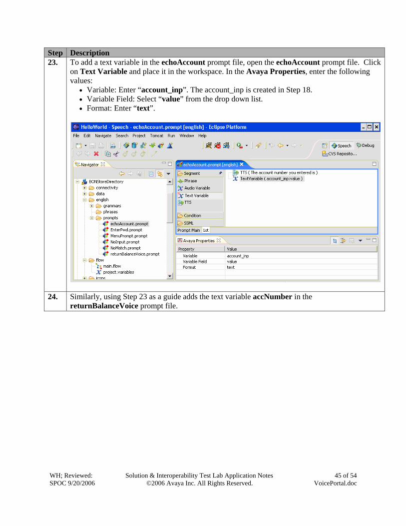
Step Description 23. To add a text variable in the echoAccount prompt file, open the echoAccount prompt file. Click
on Text Variable and place it in the workspace. In the Avaya Properties, enter the following values:
• Variable: Enter “account_inp”. The account_inp is created in Step 18. • Variable Field: Select “value” from the drop down list. • Format: Enter “text”.
24. Similarly, using Step 23 as a guide adds the text variable accNumber in the returnBalanceVoice prompt file.
WH; Reviewed: SPOC 9/20/2006
Solution & Interoperability Test Lab Application Notes ©2006 Avaya Inc. All Rights Reserved.
46 of 54 VoicePortal.doc
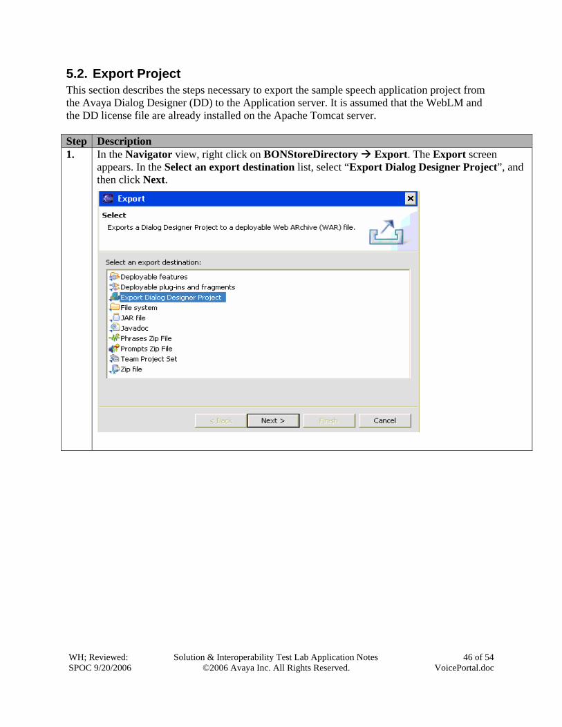
5.2. Export Project This section describes the steps necessary to export the sample speech application project from the Avaya Dialog Designer (DD) to the Application server. It is assumed that the WebLM and the DD license file are already installed on the Apache Tomcat server. Step Description 1. In the Navigator view, right click on BONStoreDirectory Export. The Export screen
appears. In the Select an export destination list, select “Export Dialog Designer Project”, and then click Next.
WH; Reviewed: SPOC 9/20/2006
Solution & Interoperability Test Lab Application Notes ©2006 Avaya Inc. All Rights Reserved.
47 of 54 VoicePortal.doc
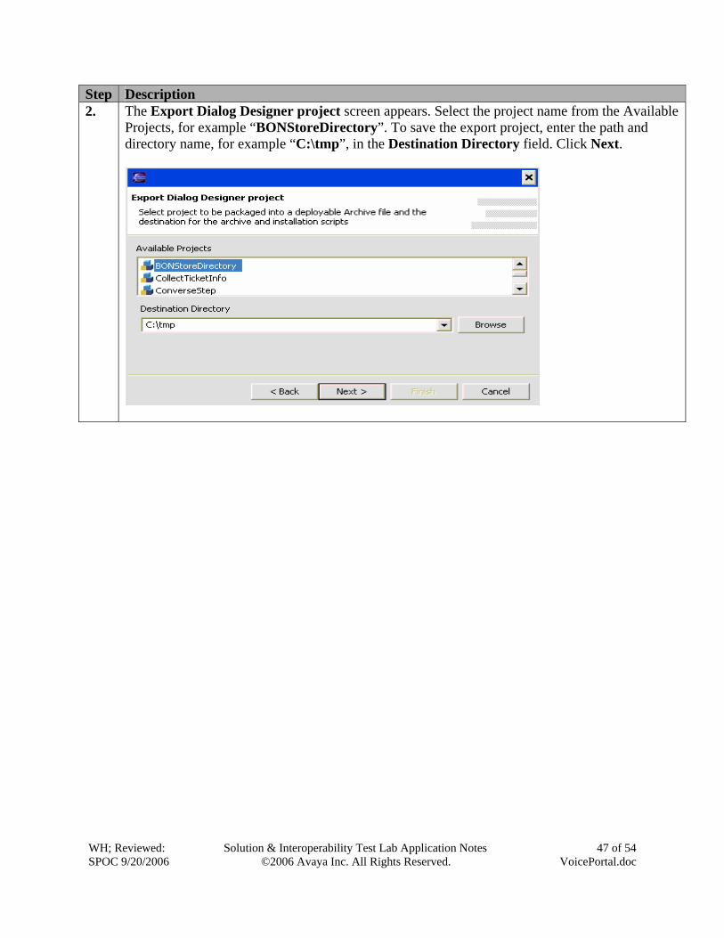
Step Description 2. The Export Dialog Designer project screen appears. Select the project name from the Available
Projects, for example “BONStoreDirectory”. To save the export project, enter the path and directory name, for example “C:\tmp”, in the Destination Directory field. Click Next.
WH; Reviewed: SPOC 9/20/2006
Solution & Interoperability Test Lab Application Notes ©2006 Avaya Inc. All Rights Reserved.
48 of 54 VoicePortal.doc
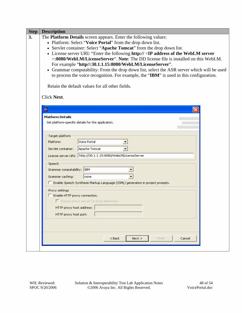
Step Description 3. The Platform Details screen appears. Enter the following values:
• Platform: Select “Voice Portal” from the drop down list. • Servlet container: Select “Apache Tomcat” from the drop down list. • License server URI: “Enter the following http:// <IP address of the WebLM server
>:8080/WebLM/LicenseServer”. Note: The DD license file is installed on this WebLM. For example “http//:30.1.1.15:8080/WebLM/LicenseServer”.
• Grammar computability: From the drop down list, select the ASR server which will be used to process the voice recognition. For example, the “IBM” is used in this configuration.
Retain the default values for all other fields.
Click Next.
WH; Reviewed: SPOC 9/20/2006
Solution & Interoperability Test Lab Application Notes ©2006 Avaya Inc. All Rights Reserved.
49 of 54 VoicePortal.doc
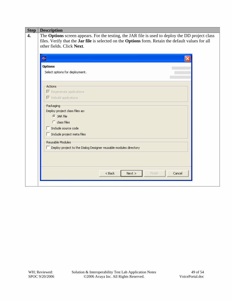
Step Description 4. The Options screen appears. For the testing, the JAR file is used to deploy the DD project class
files. Verify that the Jar file is selected on the Options form. Retain the default values for all other fields. Click Next.
WH; Reviewed: SPOC 9/20/2006
Solution & Interoperability Test Lab Application Notes ©2006 Avaya Inc. All Rights Reserved.
50 of 54 VoicePortal.doc
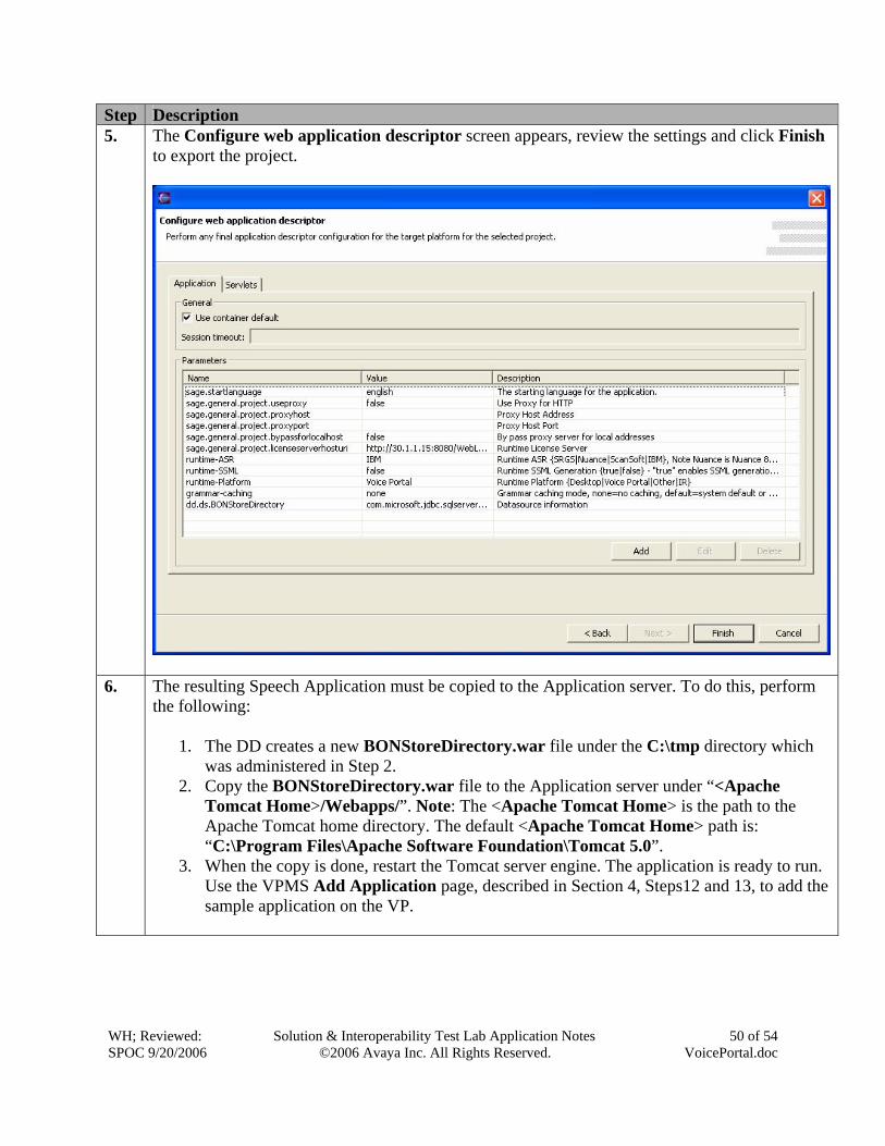
Step Description 5. The Configure web application descriptor screen appears, review the settings and click Finish
to export the project.
6. The resulting Speech Application must be copied to the Application server. To do this, perform
the following:
1. The DD creates a new BONStoreDirectory.war file under the C:\tmp directory which was administered in Step 2.
2. Copy the BONStoreDirectory.war file to the Application server under “<Apache Tomcat Home>/Webapps/”. Note: The <Apache Tomcat Home> is the path to the Apache Tomcat home directory. The default <Apache Tomcat Home> path is: “C:\Program Files\Apache Software Foundation\Tomcat 5.0”.
3. When the copy is done, restart the Tomcat server engine. The application is ready to run. Use the VPMS Add Application page, described in Section 4, Steps12 and 13, to add the sample application on the VP.
WH; Reviewed: SPOC 9/20/2006
Solution & Interoperability Test Lab Application Notes ©2006 Avaya Inc. All Rights Reserved.
51 of 54 VoicePortal.doc
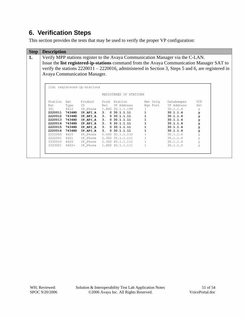
6. Verification Steps This section provides the tests that may be used to verify the proper VP configuration: Step Description 1. Verify MPP stations register to the Avaya Communication Manager via the C-LAN.
Issue the list registered-ip-stations command from the Avaya Communication Manager SAT to verify the stations 2220011 – 2220016, administered in Section 3, Steps 5 and 6, are registered in Avaya Communication Manager.
list registered-ip-stations REGISTERED IP STATIONS Station Set Product Prod Station Net Orig Gatekeeper TCP Ext Type ID Rel IP Address Rgn Port IP Address Skt 301 4612 IP_Phone 1.800 30.1.1.199 1 30.1.1.4 y 2220011 7434ND IP_API_A 3. 0 30.1.1.11 1 30.1.1.4 y 2220012 7434ND IP_API_A 3. 0 30.1.1.11 1 30.1.1.4 y 2220013 7434ND IP_API_A 3. 0 30.1.1.11 1 30.1.1.4 y 2220014 7434ND IP_API_A 3. 0 30.1.1.11 1 30.1.1.4 y 2220015 7434ND IP_API_A 3. 0 30.1.1.11 1 30.1.1.4 y 2220016 7434ND IP_API_A 3. 0 30.1.1.11 1 30.1.1.4 y 2222000 4625 IP_Phone 2.500 30.1.1.110 1 30.1.1.4 y 2222001 4621 IP_Phone 2.302 30.1.1.111 1 30.1.1.4 y 3330010 4620 IP_Phone 2.300 40.1.1.112 1 30.1.1.4 y 3333001 4602+ IP_Phone 1.800 40.1.1.111 1 30.1.1.4 y
WH; Reviewed: SPOC 9/20/2006
Solution & Interoperability Test Lab Application Notes ©2006 Avaya Inc. All Rights Reserved.
52 of 54 VoicePortal.doc
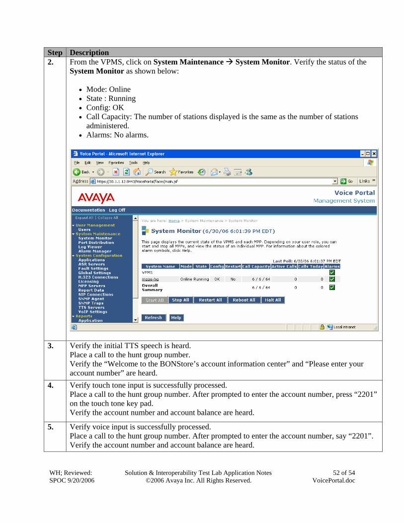
Step Description 2. From the VPMS, click on System Maintenance System Monitor. Verify the status of the
System Monitor as shown below:
• Mode: Online • State : Running • Config: OK • Call Capacity: The number of stations displayed is the same as the number of stations
administered. • Alarms: No alarms.
3. Verify the initial TTS speech is heard.
Place a call to the hunt group number. Verify the “Welcome to the BONStore’s account information center” and “Please enter your account number” are heard.
4. Verify touch tone input is successfully processed. Place a call to the hunt group number. After prompted to enter the account number, press “2201” on the touch tone key pad. Verify the account number and account balance are heard.
5. Verify voice input is successfully processed. Place a call to the hunt group number. After prompted to enter the account number, say “2201”. Verify the account number and account balance are heard.
WH; Reviewed: SPOC 9/20/2006
Solution & Interoperability Test Lab Application Notes ©2006 Avaya Inc. All Rights Reserved.
53 of 54 VoicePortal.doc
Step Description 6. Verify “no input” is detected when caller does not enter the account number.
Place a call to the hunt group and do not speak or press any touch tone key. Verify “no input” is heard.
7. Verify “no match” is detected when caller enter less than 4 digits. Place a call to the hunt group and only say two digits. Verify “no match” is heard.
8. Verify MPP can recover from the C-LAN connection failure. Disconnect C-LAN and reconnect C-LAN. Verify after C-LAN is reconnected, all IP stations are re-registered. Repeat Steps 3 - 5 to verify the call.
7. Conclusion These Application Notes demonstrate how to provision the Avaya Voice Portal with Avaya Communication Manager to interact with the IBM TTS and ASR applications. These Application Notes also provides steps necessary to develop a sample speech application. The sample application was used to verify the Voice Portal configuration.
8. Additional References The following documents can be found at http://support.avaya.com:
[1] Administrator’s Guide for Avaya Communication Manager, Issue 2, May 2006; Doc ID: 03-300509
[2] “Administering Avaya Voice Portal 3.0.1 ”, April 2006 [3] “Avaya Dialog Designer Developer’s Guide ”, Issue 1, August 2005
WH; Reviewed: SPOC 9/20/2006
Solution & Interoperability Test Lab Application Notes ©2006 Avaya Inc. All Rights Reserved.
54 of 54 VoicePortal.doc
©2006 Avaya Inc. All Rights Reserved. Avaya and the Avaya Logo are trademarks of Avaya Inc. All trademarks identified by ® and ™ are registered trademarks or trademarks, respectively, of Avaya Inc. All other trademarks are the property of their respective owners. The information provided in these Application Notes is subject to change without notice. The configurations, technical data, and recommendations provided in these Application Notes are believed to be accurate and dependable, but are presented without express or implied warranty. Users are responsible for their application of any products specified in these Application Notes. Please e-mail any questions or comments pertaining to these Application Notes along with the full title name and filename, located in the lower right corner, directly to the Avaya Solution & Interoperability Test Lab at [email protected]