hvdc unit 2
DESCRIPTION
HVDC UNIT-2TRANSCRIPT
\ d',if - t H!)Ltq4srhr" G
ll "'.o 'th\ a U:ilt,'.0-rlat
LJ"t{o
3qun
:tIed.
il
www.Vidyarthiplus.com
www.Vidyarthiplus.com
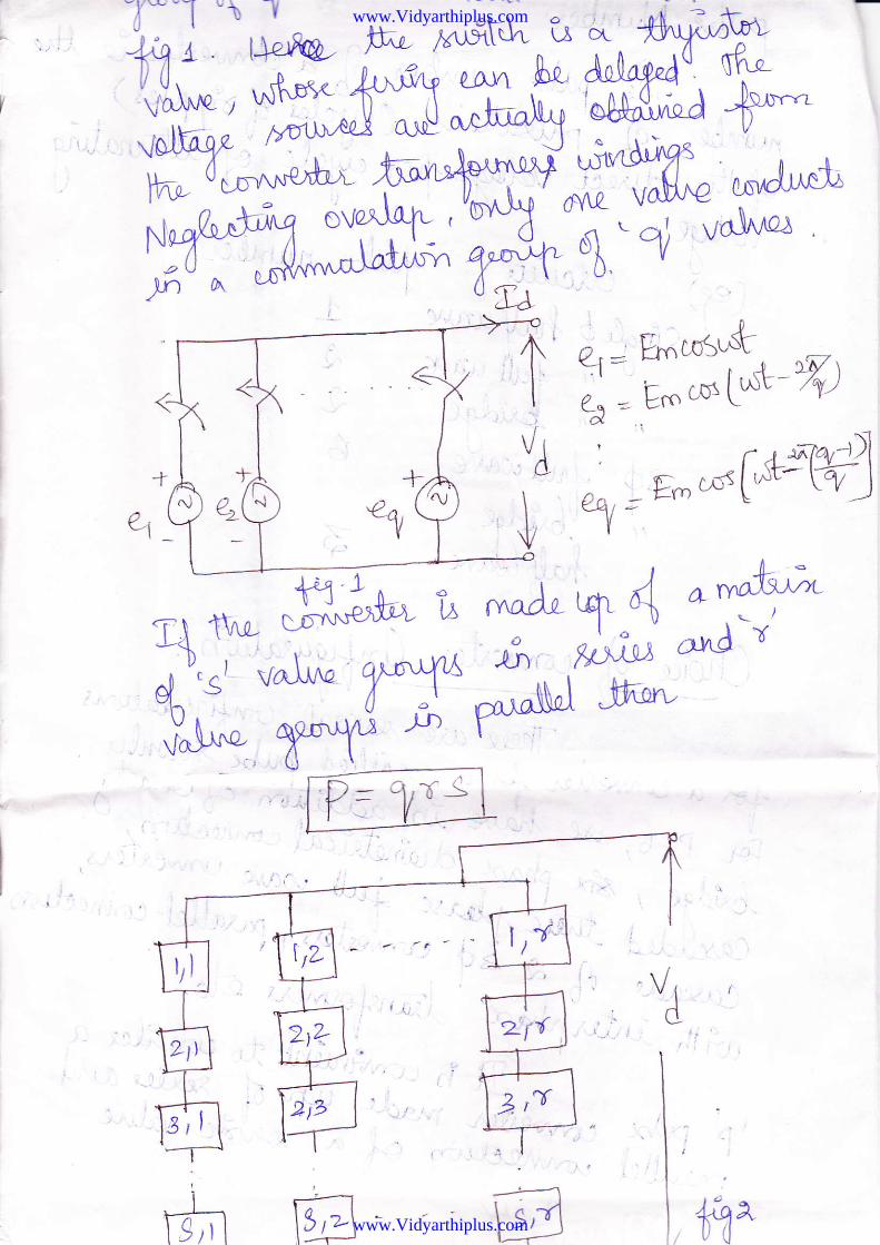
a, : E ncoSudf tF t'' . ,*[ &- "/l)€-J -- .tco "'-
L
o:^ -E-*F'H]L)a t -I\ry
\ s,t1l--->w
www.Vidyarthiplus.com
www.Vidyarthiplus.com
^:r "- -u Qi
i
.r#, tL,
^AL
VJ"* Utrlq
*t*
#, SI prv t #*"A"o-tP )'^At" qt*
t^V
6;:58;"6W
O.Juo-qo+a llt?**''
www.Vidyarthiplus.com
www.Vidyarthiplus.com
1
II
i
l,
I]I
:
i'
,..ii :.
d.lu' *bt9r.v
'' (gl 4'-D
i
a-J -c>-'Jv - <51
kVn)
1=oJq
/^J".fr ffi= Pa&,
www.Vidyarthiplus.com
www.Vidyarthiplus.com
t Slstems ^er-b, G
\,w. \9
Forq=3,
_&- = 1.as1YaoI a
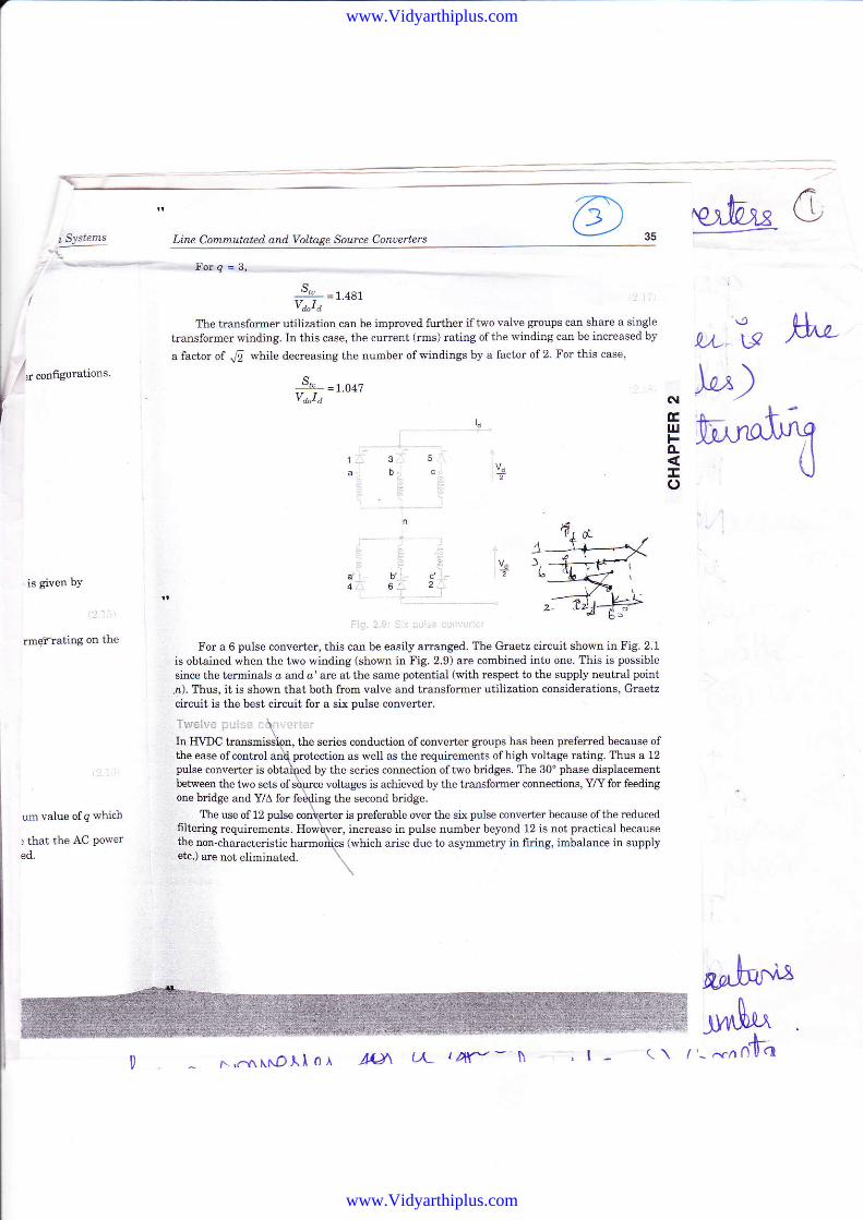
The transformer utilization can be improved firther if t i.o valve groups can share a single
transfomer winding. IIl this case, the cunent (rms) mting of the winding can be increased by
a factor of .r[ while decreasing the number of windings by a factor of 2 For this case,
-$- =1.6a7va"I a
3 5
Ys
Ys
6'is given bY
rmqFrating on the
um value of q which
) that the AC Powered.
Ttferrr.- ;_j ., -l
For a 6 pulse converter, this can be easily arranged. The Graetz circuit shown in Fig. 2:1
is obtained when the two winding (sho\rn in Fig. 2.9) are combined into one. Tllis is possible
shce the terminals a and o' are at the same potential (with respect to the supply neutral point
,n). Thus, it is shown that both from valve and transformer utilization considentions, Graetzcfucuit is the best circuit for a si( pulse converter.
In I{\DC
The use of 12 puls€flltering requirements.the tutr-characteristicetc.) are not eliminated.
the series conductjon ofconverter gtoups has been preferred because ofas well as the requirements ofhigh voltage mting. I'lous a 12
by the series comection oftwo bridges. The 30" phase displacementvoltages is aehieved by the transformer connections, Y/Y for feeding
ttre second bridge.is prcferable over the six pulse converter because ofthe reducedincrease in pulse number beyond 12 is not pradical because(which aiise due to as5'rnmetry in firing, imbalance in supply
the ease ofcontrolpulse coBverter ist etween the two sets ofone bridee and Y/A for
E b,x^It^qo- ltI\Jo
7lL
r-,.f\^NDll0,A AIJ\ L,l rAf"- T\ ,l-J^$4^- ^.^n'[h
www.Vidyarthiplus.com
www.Vidyarthiplus.com
__:-=aF
-
Solution
'r'< .,r i1.rr!!,s q : ']! ?:l:e aniiilerieis
that the turns ratio of the
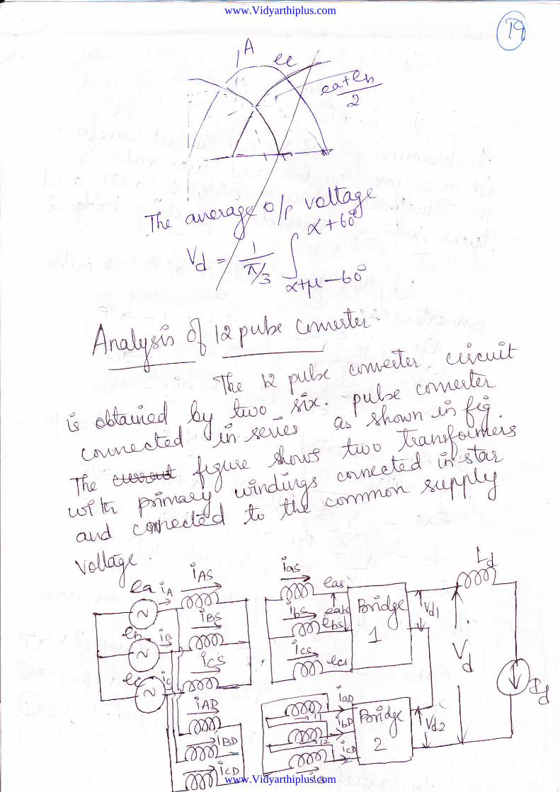
To analyze thein Fis. 2.10. Tl]isto the common supply The currents supplied by the supply are the sums of the currents
flowing in tie two windings. Thus,
of a 12 pulse converter, consider the convert€r circuit diagram shown,o transformers with primary windings connect€d in star and connected
:r feeding bridge 1 as 1:1 and the tums mtio of the
as 1 : 16. Assuming ideal transformers, we will get the
+irolti", l
In determining the voltage current waveforms, therc is no loss ofgenerality, in assuming
transformer feedilg the second
I
43.'ttf;r!( 1
the ma:imu.ra DC power sld lraD$ur u<rFor a 12 pulse coDvert$ with q = 4, s = 3, . = 1, calculate tl€ maritrum DC lower eno
ratings (valve windings) if PIv rating of the varve i" " ".a
J. .-" "'-"", iatlng is I newort the
problemifq-3,s-4.r-L
with even value of q, PItl = 2E -
1t 12V n aBV. -:sE sin" '- "inl=:Y'y=t-35y- n ' a fi2 4 fi
1=J4=I-t-t. =ztr'lqPd^-=Vd.Id = 2'70v1
s, =oFy t =r4r =q.zqsw'' J2 2^12
withg=3,s=4,r=1
PN = 2E^Eos+=2E^t's30' = \lst^
u* = gt t
^ "^I =t} k"; 66' = { = r.srv
Id - Gn - '&, Pd-d =vd.td =1sr<{3w - 3.3rw
s,,=e+1=1#=4.sw
with only six windings on the valve side
s," =ftw =s.+esw
www.Vidyarthiplus.com
www.Vidyarthiplus.com
on S!'temi
r. Vot. PAS'
of Electdcal
E Spectrum,
6,,..-/(1IINE COMMUTATED AND VOTTAGESOURCE CONVERTERS
2.1 INTRODTJCTION
In this chapter we will take up the study ofconverter circuits used in both Line Commutated(current source) Conve*erc (LCC) and Voltage Source Converter (VSC) stations.
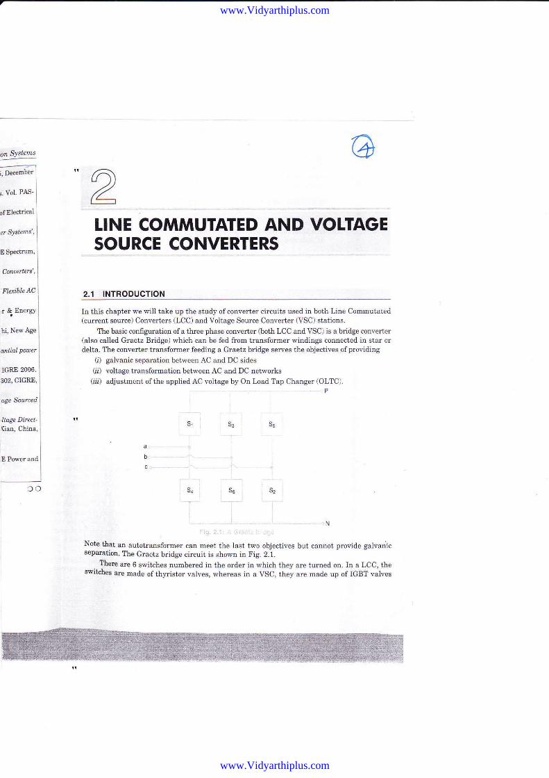
ltre basic configuation of a three phase converter (both LCC and VSC) is a bridge converter(also called Graetz Bridge) which can be fed from transformer windings connected in star ordelta. The converter transformer feeiling a Graetz br:idge sewes the objectives ofproviding
(i) galvanic separation between AC arld DC sides(i) voltage bansformation between AC and DC networks(ii) adjustment ofthe applied AC voltage by On Load Tap Changer (OLTC).
P
s3 ss
s,s4 S5
N
Note that an autotransformer can meet the last two objectives but cannot provide galvanicsep€Fatior. Ttre Graetz bridge circuii is shown in Fig. 2.1.
lLere are 6 switches numbered in the order in which they are turned on. In a LCC, theswitches are macle of thyristor vah,es, whereas in a VSC, they are made up of IGBT valves
302, CIGRE,
ase Sourced
'Itage Ditect-{ian, China,
E Power snd
oc
www.Vidyarthiplus.com
www.Vidyarthiplus.com
IIYD c Pow er Tt ansmryUg!9!!-!
(a se es connection of IGBT and anti-parallel connected diode). It is assumeal that the phase
sequence is'abc',
2.2 LINE COMMUTATED CONVERTER
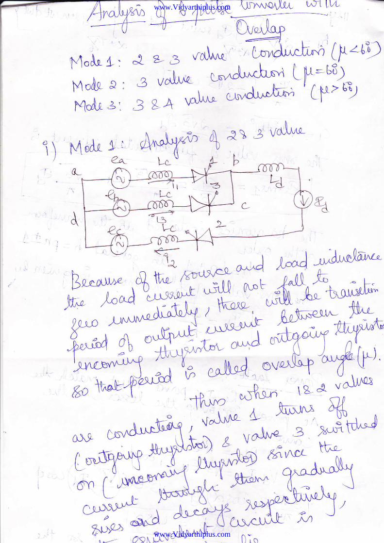
2.2.1 AFllysis ri Graetz Biitlge i"leEiectins Overiap
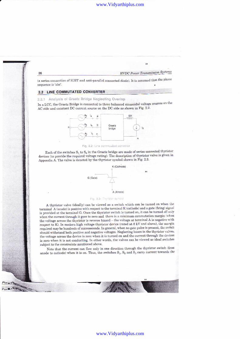
In a LCC, the Graetz B alge is connecteal to thr:ee balanceil sinusoiilal voltage sources on the
AC siale and constant DC curent source on the DC side as shown inF19.2.2.
Fi.t 2.2 - : i.iri'.r!iair'r .!i\,.ief
Each of the switches Sr to 56 in the Graetz bridge are nade of series connected thynstor
alevices (to provide the requied voltage rating) The description of th]'ristor valve is given inAppendix A. The valve is denoted by the th,'ristor sFnbol showtr in Fig. 2 3'
K (Cath;de)
G (Gate)
A th,'dstor valve (ideally) can be vielted as a switch which can be tumed on when the
ter-rnitral A (anode) is positiv;with respect to the terminal K (cathode) and a gate (6rillg) signal
is prcvided at the teminal G. Once the th)' stor switch is turned on' it can be tu?ne'l off only
wten the cur-rent ihrcugh it goes to zero and there is a minimum comrnutation margin (when
the voltage across the tt1'risidr is reverse biased - the voltage at termitral A i6 negative with
respect tJ K). In modem high voltage th,..istor device (rated at 8 kV and above), the margia
required may be hundreds oirnicroseconds ln geneml, when no gate pulse is present, the switch
should withstand both positive and negative voltages. Neglecting losses in the th]'ristor valves'
th€ voltage acmss the device is zero when it is tumed on alrd the current through the devices
is zero rpiren it is not conducting. In other wcrds, the valves can be ilewed as ideal si(itches
subject to the conshaints mentioned above.
Note that the currcnt can flow only in one direction through the thlristor switch (frorB
anoale to cathocle) when it is on. Thus, the switches 51, S3 alld 55 carry current towards the
--.{'
www.Vidyarthiplus.com
www.Vidyarthiplus.com

terminal ?'\vhile the s$ritches 52, Sa and Sd carIy current fiom the terminal 'N' The directcunent Id has to flow through at lea8t one valve in the upper group (S1, $ and S) and one
valve il the lower group (Sr, Sa add S5). Neglecting overlap between any two valves in a group,
we can state that;nly one,ralve conducts itt the uppel group ol lower gtoup Thus, in a cycle
ofthe applied AC voltage, these are six equal intervals as shown i4 Fig. 2.4.
q + 360'
NtrulFco
FiE.2.:r: ;,l-. :, I ,.r:-
We assuse ihat the switch Ss is turned on at o, = c[. Prior to fhis, switches S1 and 52 are
conilucting and we also assume that the switch Sr turas Qff as soon as the switch Sa tums on
(neglecting the overlapl Overlap between the switches 51 and 53 cannot be negle'fed ifthereare inductors in the circuit (due to leakage reactance of the convetter transformer) We willanalyze the converter circuit $/ith overlap in the nert chapter. Table 2 1 shows the DC voltages
across the colverter (VpN) for each of the six intervals.
Tabie 2.1: Da liL,; lalilt. D,ii . i'ii
lntewal
V"l*s C".d*tt-qVoltage (VpN)
I
,3 gAl
4,5
lv5S 6J
VI
a
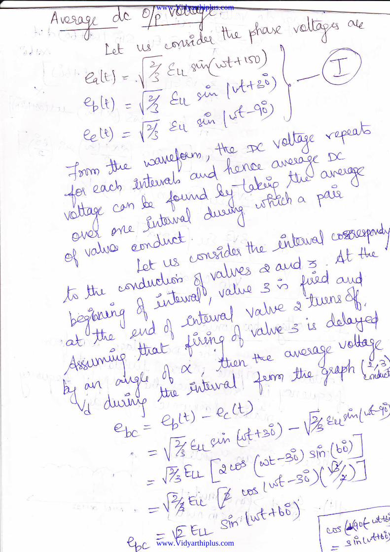
Note that the voltage a$oss the valve (switch Ss) is ebo before it is fired (turned otr). Ilwedenote ero
ebn : {24rsir.rr*the voltage across the stjtch S3 is negative when irt < 0 and becomes positive when(D, > 0. For a thyristor valve, w€ can delay the iuin on by a delay angle (c{) by applying a gatepulse at ot = c. It is assumed that the delay angle is constant in steady state.
The expression for e6o given itr Equation (2.1) implies that6
".tr, = Jle-.r',., - Iso'r I
t,te6rr l = iaEri sin{(1)f 30")
il;e, it) - J;Errsin((])r- 90"r
J
l
www.Vidyarthiplus.com
www.Vidyarthiplus.com
-/v- ,=;i^N* #- "ry a{a
L"t\.r.Jusn'Ltcj\\,2>,.
*.5'= W;*c*1'*) \ I
%rt) = d';:'; t't*'i)\'--Q!
%N) = d;:; t-n4t )
-"\--,,\'^trffi"#*##,#?-^d^!ffiS,b-o Htr&tr.^Tff^3*:m" nls
*^.q o"(te'l*o or^.tt.oryd tr#4 uil* tr;.**gl a a,,,.d z , ^
f..b., *9il4^,,',ffiff$ffiq#Ai-*t^ va\re 3'\A*T4
fr;tr, ?il' +^*rt t\ ; Toff. ^;t#,
ffi'.^k A;e"*rF Y'"orq
\1 -# T,,";',!-,, )-Fz:.*,*u
:Y;#ffK:*ilqfl=fv|rn V ,*.**ut) I-_fr["y
?b, = rEuw si'' Lu{t'' "'/ [t:n,*n
www.Vidyarthiplus.com
www.Vidyarthiplus.com
, sfr 1r"€+uf d .^C
D6t{f
f- L6s turt+ 5UL
_xs F*.r3)-wrtt"2l
^ ef)*e"t\ d- -/'
'xoqt) y).-1I
.ar
f N+43r(JvletLs
d,gzrtrQu I -,a \--4{
+&.ur[,er t""\ A' iI"Lt Gtn
I
u? uo[*'
t*['e{;"di.
,rI
,Fi = StJz
1.- fl1,^a\ q,(i
o& r'{1
n tfu/t -t-tnfi n"u
i l.': '
d Mt66 o(+{
www.Vidyarthiplus.com
www.Vidyarthiplus.com
Q13 = *€6.xsx
^ =:--?ript" *G Ls'n*'L au&]"*r.nZ t L__o/g- d- ^ , .^r.. ,1- n s\ I ,*n;"fi
_Cs,, =nnfu&u'
www.Vidyarthiplus.com
www.Vidyarthiplus.com
tT.u+d tftv/-
w
----E- 6Ery*: % \ /3
y-
X ^/'lJD "W .
a,"= dsa- Ld
. ,/f,t"\,
r*.ft-l )
0.,,f =
www.Vidyarthiplus.com
www.Vidyarthiplus.com
C1 --fa,"* - *?'ftw vw Cu{ q
x f .e! tk'
&-^rl =il6/r
www.Vidyarthiplus.com
www.Vidyarthiplus.com
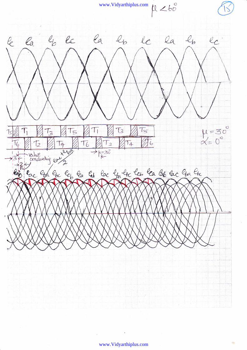
wt t.t4
U v : Wa,\rtqp4:1 I
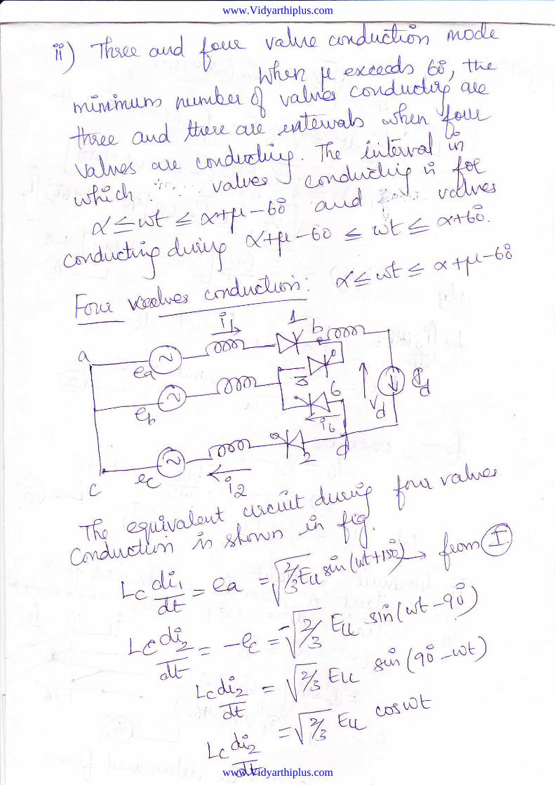
i)
1..1oAl 4 : J 2' 3'ldIA^{', -_('uvrd'uchn'o,
(tl'*Dffi
*, ,*n u"l^* t^'J'*h^i I P=-bB)
tqd'u '31 3 t;;^* cl'^d'"Jh" ' C Pt ry
4 ,ru 3 v')"[^*
w14ry '-,'* ksJNA RrI^Y,,"AJ;-' !"$^*J
ow) oo^ a?.nnr tl6-
, WYYcDcrJS't
t*qf5
www.Vidyarthiplus.com
www.Vidyarthiplus.com
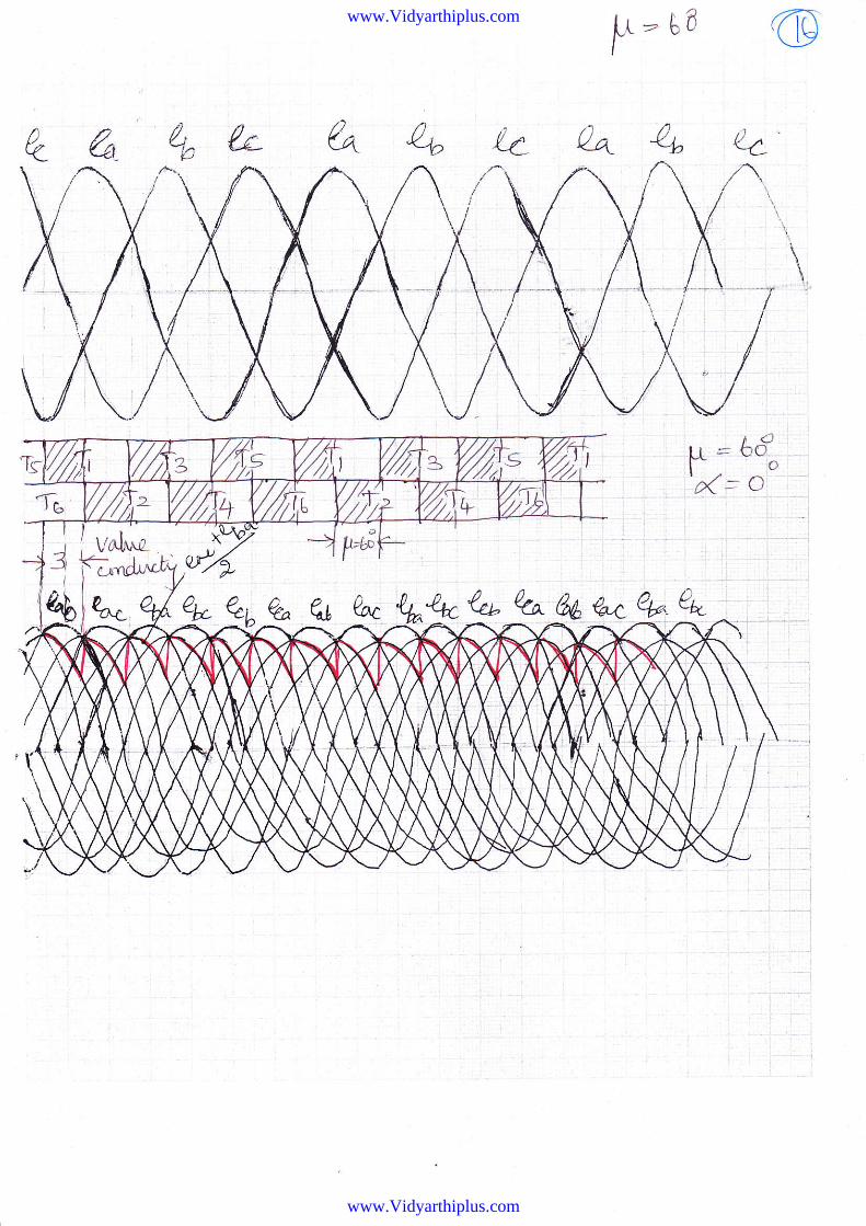
4"- ry'i,l?-'* "@
r^,s *, O : 9, ^ t)i,_,-.df#,iG Eus^i","<t = LtLF- l:4
WAh ql*Pm us-^rter,.t-
: F JLcdJ?€t'H:il,== rffi*'x\rf
J*tc aF */^o/N/T' 'c (; F''/C6sx-*1"+f'J
www.Vidyarthiplus.com
www.Vidyarthiplus.com
@
owQ
"c"FW
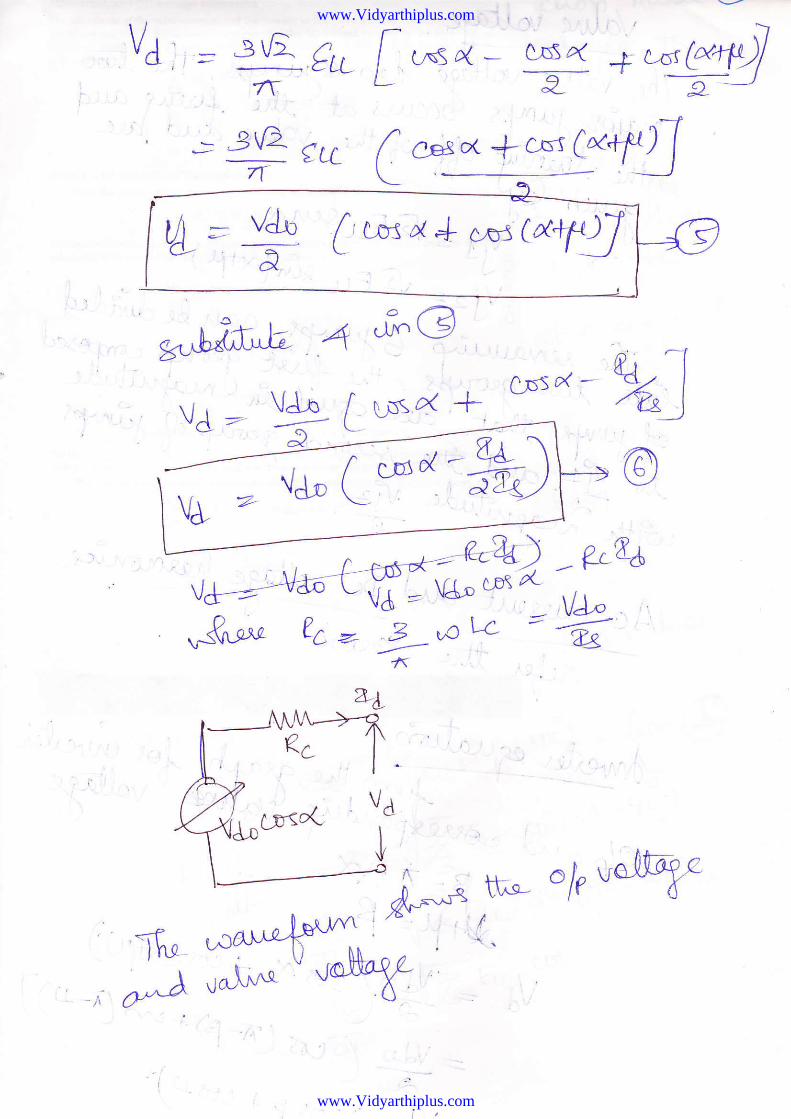
8J =,& C.*o - k$ L'qq
. or-. -1,^.\oD s*
'.svfi'5X,'I"t-p4 \t*--l- \V>-(, r
www.Vidyarthiplus.com
www.Vidyarthiplus.com
, Vd;,= igaf\'' ;3tA_gvtr
L=
VJ -'
V;2
It
.1t, tt
CJS 4 -l C-6fta<-
*.tIC,
o* n + c^r A+:^91
@
"1r*W
www.Vidyarthiplus.com
www.Vidyarthiplus.com
6\ rtu
\ tc . - ilt Eg-9wua1 d
vll - ^ t .-t-rr \Ii " G Eu__d_,1*T.)V? -, =-J-- /\ !.t t^:= ; "; ce,^ a" A"RJ-"d6 t'^#
a; "'Y*c,ff #":iffi r*1 e^"e
t" !ts *?J" rfi-,Stu'i^ofl-* +
n
At* &
C0-Lt'l,rg at
Ao c-t*$Mts 4r'^d:- ${-- w)sv<
,ho^'4)0
'?
www.Vidyarthiplus.com
www.Vidyarthiplus.com
.r.tl , t: r-:: i , :: .. :.a : _ -.
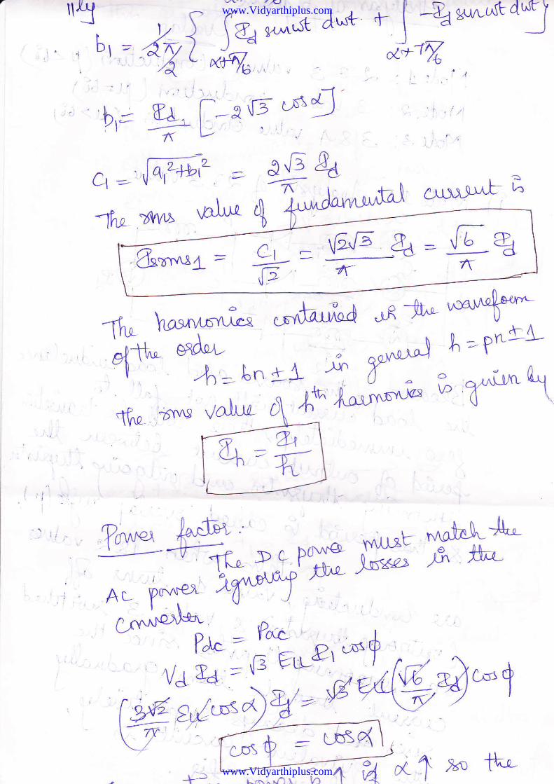
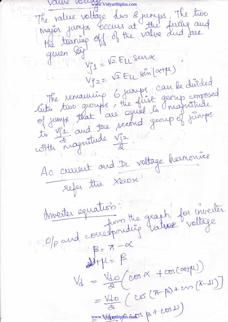
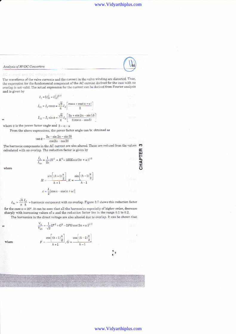
The waveforms ofthe valve currents and the cu-rrent in the valve winding aro distorted Thus,
the elrplession for the fundamental compoaent of the AC current derived for the case with no
overlair is Dot valid. :[he actual expression for the cuirent can be clerived ftom Fourier analysis
and is given by
t, =1t1, + tlrlLt2
1rr=1rcosQ-frl*-+*-I
1,, f,sinq= 'G [ 2z + sin 2o - sin l 6 l;"1 q""""-*.0, l
'where O iB t}le power factor angle and 6 = d + u
From the above expressionE, the power factor atrgle can b€ obtaineal as
2z + sin 2cc - sin 25
cos2d cop26
Tlle harmordc components in tl1e AC current are also altered. ltese are reduced from the values
calcu.lated wif.h no overlap. fhe reduction factor is givea by
* = *r' + K2 - zaKeos(2& + dln
1lFz +G2 - 2FG eost2a + u))rt2
"o.fta*rr!l *"ft,, -t,i lp= L ").(]= L z)
i+t h.-1
ctElrlFA!o
.i"f,r *'rilH= Li-i -"K =
"r[rr-ri]hl
r=1lcosft-co6ro-&)]2'
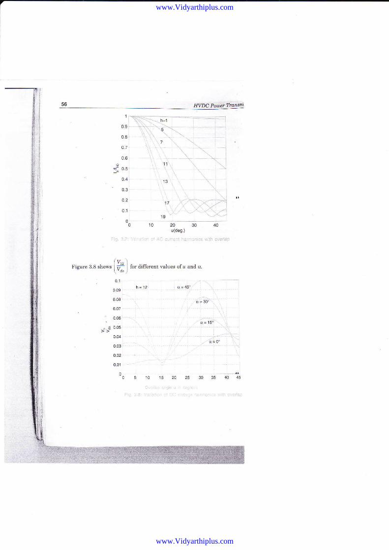
- J6I'I* = ;; = hamonic comporent with no overlaP. Figure 3 ? shows this rcduction factor
fo! the case d = 30'. It can be seer1 that all the haxmoEies especially ofhighet order, alecrease
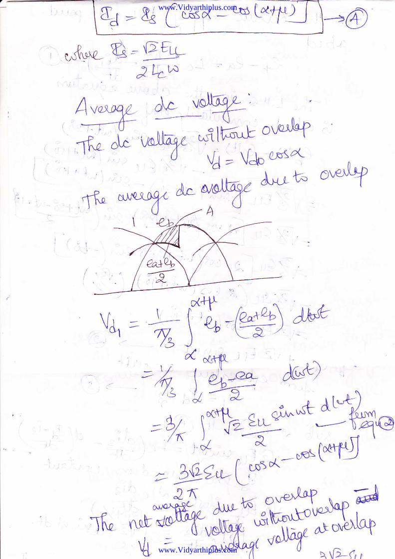
shaaply with inereasing values of a and the reductiotr factor lies in the range 0.1 td 0.2.' The harmonies in the direet voltage are also alteritd due to overlap. It can be sho*n tbat
whe€
wher€
vu=Ya.
''t
www.Vidyarthiplus.com
www.Vidyarthiplus.com
1
0.9
0.8
o.7
0.6
4.4
0.3
0.2
o1
00 10 20 30 40u(deg.)
,.ic _.::..,r,.,:, t, r:.4 i:.-:,r:.ir.r..::! 'rrih cveisp
lv." \Figure 3.8 slows | ;L I for ditrerenr values ofa and cc
\',1" )
01
h=12 o=45'0.09
d = ab; :
d= 15"
'.: id: O'
0.06 -
! € 005
. 0.04
0.03
www.Vidyarthiplus.com
www.Vidyarthiplus.com
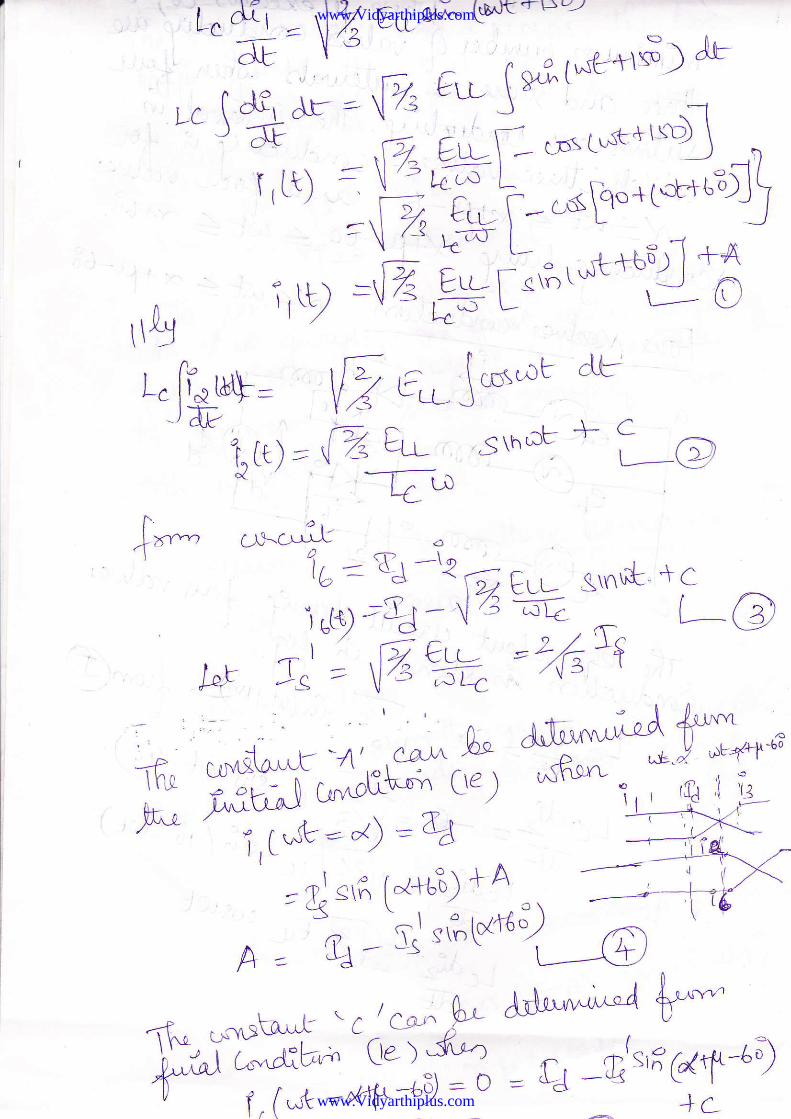
-_\4- \ r5 L l(4g'vj- 4\J fr,.^,ir' Ai^*t f"^,.aj^p,
###cfr{j% ffi',*,-. J,,*€###* /, r*';ir],$-,g- {-"-@
r ^ di' - o-a, )(tc*Y a \uC -l-u-c&=v-4- \; _ u,f.lG ei)Leig__ _or.:lZor-"'.# \a
"E-
nn *'[ti '-'"of
Lcdxz- = \ "'" -e r-:- r attailt
, ^ AL =\7, rti_.
t-t ,
{b
www.Vidyarthiplus.com
www.Vidyarthiplus.com
IT
I
djj
+-c, ,,_'L-l?)
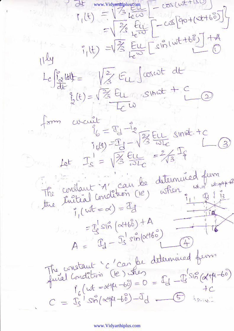
,lt*- ,r*.-fu ar "lb__ aJ -rr ,; F,._ s\nu*_ + c)rg-LJ - lzz:'"e."o ;G)
-l 6 €Lu , ' / r'W ,.t' = l7s-F+ "-/'F t
t "ilj dii":il? Eit-e Qu)€'rtsu-z- -dL
- \'6 f, t"sg".r6;
Jr- 'r- '''.-V, E'- j*^ | r-1LtJ*aF =
,,ao err-. .*Lust+,sj --5)
TrLt) =\'t-;;l -{.l a eL,'; f-- t,sp"+tr+t-"lj
=\ /-l \try L-- o r rR.,-1 .+_A\ l- L"^ L -''1 . /rA
=@ Egt"'?,tuts]--d'ldL- 4
www.Vidyarthiplus.com
www.Vidyarthiplus.com
=-W: -ilt*?""r}-- \l /r r-d- |
=t2-*5*'**J*64
:,i J|--
rr&
asI (Lt) _
i,g
.l- c'! ,,-L \))
| -ut2 \ CfSt'^lu\-tl-_ -J
dr'
h =oq--'t''fre*ti---@
www.Vidyarthiplus.com
www.Vidyarthiplus.com
-H^,t a^*NfA'"^\ vJ$nu-u"
*".cal
d+rt-L- uC <9-e
U
C^\ L-
TL
zn -!-
codtldtg,
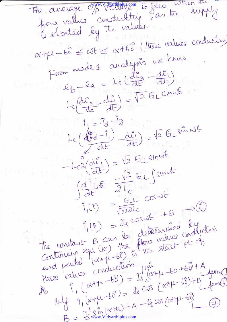
F"*- **Ao {
4-A-+ ='
L.e?--*).P
d; aLetn^rt^)Y:\
?- 2RLp \'^rr \rlz\'{J o ,$tt
ort-Af, Lfi'^!- vdur.nj
atubryf'n roz- L*^u
, ,h^ -df ',\Lctff- E)
aoi, -- % -\al, r lb+
j) -+i\ :'F tuGA1-
\ ).A aY-/
,;6)=Yfu_n''xr(01:; *ai- !sr"'^{"
)F ^ 7- cF(.:Fi,t9 -ff, -l t_B -u@f,tt; ---34T:*^**, k^
kffi##$ru#nc,"r.d pe'';nu t -a-.p *!frop+o +60 + lar-AS6.!P 'vn\-i'o (
^p, i, Lot *j]--#S'i*-6"r%i"^€
c r/,i& ; ;TS,i_l; ;-
13 ro1 (*-v-'9,._@r-1 l/ _
b-- --)
www.Vidyarthiplus.com
www.Vidyarthiplus.com
l"-* /L{\"w'r\4er4 t..r-e lto'""'a (e) .6-u\,.*";. { c""r-l-''L
t1tisil 1J+t.i ) A i ai'r ac-:! Tff**ry
'-'s !."uxidrtr,.r Cil. v".l-.* q u t 'I ^,^s("{+{s)l 4rs,i', (I"rD + A : q "'(Ftl'^-aD
1l cx tx-\c
-e --'- = & -- &lclnN + &l srF' 1x+p -6€) q
g,-b'&i/& -;U-- ,",t "4 $ A ^l o
I crsr (k+rD;{.*i.Tr+e - qi<^i6N+tQ
-& crss ( dt"--68)
= Zl st (*q* -bF)- 81st?-' "<
4{ = -rp c.d 1x+ 6o' ) -C .,:,Y,#"-,1;1ff,f"" -; *rnnp,
:"? ":;r.1%;)J:F
d [*i s*rct'i'"-?1"t.--1r5-6f +str
tS\nx - stn \
g.'r\*(Ye&*:I
fl-l , t!,',-f- r.n 10 -;E-d -a- l"O{
hv^'y rlf:ryj
- cortx1'uq
www.Vidyarthiplus.com
www.Vidyarthiplus.com
atoI
c
,^=;t
)ea.22<.3'
^o'.11oo
€r*
^rty.-bE . o^ | ^ X4'6O
=2.- f.''n +(gy^
\-:-;4-P-bc/
(e4j0g!46 =b ^
z{ =-@9
=+WA^D' |
^^ e1-i!-*
pa L,n * ul,; Vt q'udd
V3 - 3 fft,e^€rLrd*t*o\- -Jg,g1*
F,^+il;*2 l3^-6Y':G r&€',\u,' rs'i^
(6ftat"{..9' f t-l - "_ t
v-,-:t-66tt*tt=-Eia,'[t*.qt *** +zzl
=gvsfi.;)*'p*p",1l"ur[il$ 1t- ]
r.r._=\ _st{a,I
bo i^-,,, \Ar\L
t ;^..: V'" - \, ^.-lx" r /f$L*\ .Kr\ij_ \ "
www.Vidyarthiplus.com
www.Vidyarthiplus.com
l- i l r-S - -- a
i
=+WAuk)J+pe
* -
pa Lnu* u!; Vt q't'u'^tg
Vr- +fffa€r.6*_hu=;erq:-,f;4** g'5(#':ry\;;il*
= _q\1."'L* *.qt
*** o^11
=$Usr"a t4-z1) -'
-q.^b,rkfrry +ai* * t'ti"'D
*"ffi;=;r**ffi
www.Vidyarthiplus.com
www.Vidyarthiplus.com
.cLft-u o"'-"Ar
&"..1 tk-'aLL \,2
. rOrld.. {-o#
www.Vidyarthiplus.com
www.Vidyarthiplus.com
I z..a.l
f" 4^ k-\-c.r_ l-t
(]
V=3cf= o"
-? lr1:i'l+
q ?"c '4+.U % A e"-c ep Aa,
www.Vidyarthiplus.com
www.Vidyarthiplus.com
a& +b abU
ft= bd
u4"
,@
u
p-=t,x-
D.L6a
fbc
tu W U44.U {6I val"c
F"d,"IQt- a
'j-6
TI?:rlqb
www.Vidyarthiplus.com
www.Vidyarthiplus.com
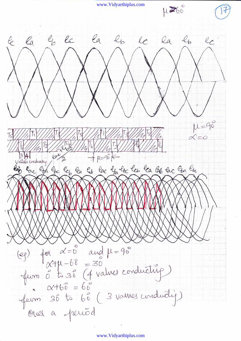
IFtci @r)Y ,/t-(-!-bt'tu4u"q,(^{-t
^J
Itr='10X=-o
D. e n D.-P Yb I k"r "ekA%A&4.ekeL.y--q1
eq
+-^,*, 28 t. t; ( 3 v^imclnCIuo( c\ +.LAA
www.Vidyarthiplus.com
www.Vidyarthiplus.com
38++
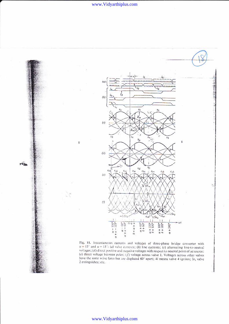
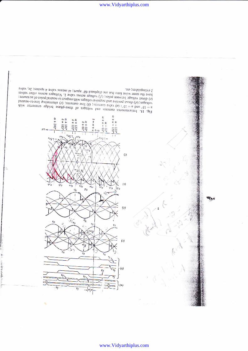
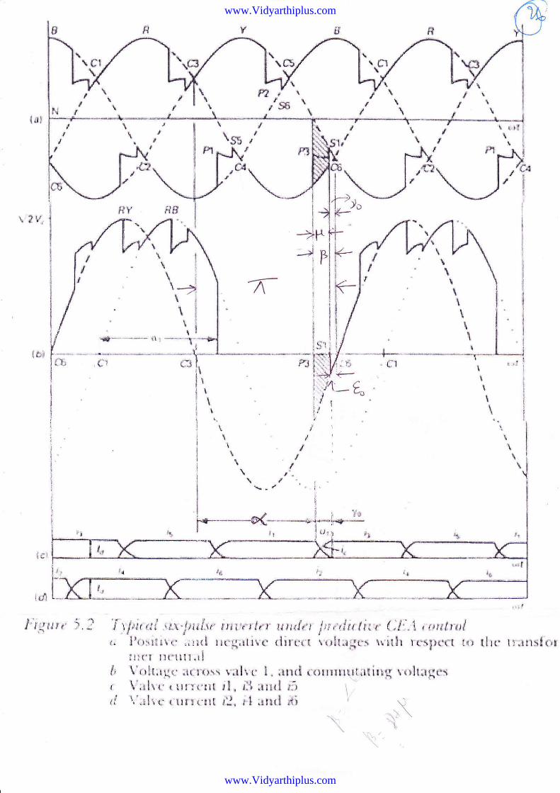
l.ig. 11. lnsiantan(-ouri currcnis irnd vLrlt3ges of threc-phase bridge convcrtca with1.-. I5: and l1 =- 15 : (d) yirl|e ciIicI1ts; (r) line currents; (c) alternari g line-to"neutral\oltagcs; (..1) dirc.t Fosili\e and ncgati\ e \-ohages with respcal to neutral point of ac soilrce:(e) dircc! voltrge baiwec L!olL's: (/) voltage icross valve l. V(tlagcs icross orhcr vah,eshrvc tha samc Ni\c fornr bur trc displaccd 60" aparti.li mcxns \alve 4 ignitcs; 2e, yah.eI cxtinguishes; etc.
+o
++1: €o + i66tt ll d ++
d: I B5
www.Vidyarthiplus.com
www.Vidyarthiplus.com
:ll:1. '1:.:.,:'1,,", r olrr\ srirru,,r:urd'
0y ncrrldrri r,r rnq L,,ror ",il;]
.li;1;":rr,'.:::i[:J::1:;,HH|il]'$,.'"X1,':J,l:j::-o:'1o, ri; ,*r,'.,'".""i,.".1',']"1["''u'*'urprrnsu-or.ir,r irrr)EUrrre <.,, ,*,"";.r'i"l"lll l "',,.:t., r"'1,"r,i.
'..';,;i; ]::ll| 14
qrr\1 rr)r!^u\)r "rp"q ".rq,r_r".,fi-1; .*1,Y1.':::-' . i.\r,.\ (ur'.sr -,r puD sr .r)!d!'t{i^ pLl. srU,lltnJ sn(iUntuEtsul .ll .b!:l
ac ; o
++88 rr ll
eeq EE
++33
,,q.r _
I'I
t-,
i.
J,].,
.!i
IJ-l
www.Vidyarthiplus.com
www.Vidyarthiplus.com
/=-'
u
11"
A*W 4'uP"l"- t,*^t'l* * . ":., r
--v- :-::,t, uon^'il* *t*1fu w *A'* Y.,o^, rrMns^yt
un ;B^fw"/^ ffi* t": -I:
"X t" F f"#
at^
eat:
b,*
www.Vidyarthiplus.com
www.Vidyarthiplus.com
"\ g =- i 49'\'t gP
o
f * = int+lgP'\1
--ice1- ice
Ip! f'*
^rJ co""t''nk tY-d\c$i&h4 /
^\a "fTY Xiil' 'L^d
fpi,,5 *'F&* 'ry {tks '^ fuf-
u*n^-"'fu" Yq €u6("rL'Llso, ---" C
?:WI;,$l;il=q4,*;ffi s'^-^'\% 4{h"Yf,-i**-'*f#€ud t*t*]1:3
a-pxg = \ lb ? f uft+Zb) ^Bhs =- @ 1. :'[*f -qi)-{9
r €4: = ,l/t Bt-t-
^
11, A'i' 'il*f" 6b v* Y Y fr':f*-
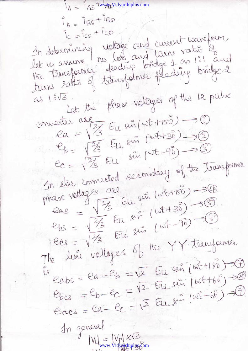
2* Q*b, = eo-e+ =-{t €o 61G+r" Y=@
Qbo=7_4::'*3 Ir*1 ffi€-a-f,t, = Y-A- q- * v
4t 'i" nt"J- t lV,l=\vr\xe", '.;, rO"t3o
www.Vidyarthiplus.com
www.Vidyarthiplus.com
j" ;t lta crrr'r^'-q-ctel Auri^4'o,'rq-1- tr
/dn ,Z lie^ , -*tuT
^JY'nxryAdqr"b t^ '' T an* voftup u
e! t{1^") .lb ''r-+--3 ^ e4is' ' | €eLP'= 'qQo l ''ft* ''i t >@
Qnbp=rEE:.y;i _(."6 -"O?b>rD=.ft * ?1-*_a.f_,@;o =' 'E
'Fu-
H'ffi"] t;;ffiW;Hns'mA,Lrd ?iu a-fet /^-v\r' v
* #"4" il- nu*.;oihr-K^rt,r1'v T.*',r,q,qff*;; r'."fl*+,1
ry,. qd$k,"bff*,"tr#;%
o{ 1il; *' ftffi c r-bakf,,*n ?'Y "4-# il;,4* 6(trxnr*r lY l#" g$orJ^"lcal '/-"
\o
='o
o
!3 t3 t? ,-lT a t
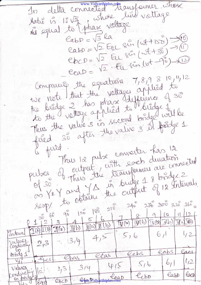
st0') I!&jtrb) 'gi SDi -, oJ-lz- S-tbI @llta) I 3/b) fi1")lTrAir*"'L rL)6 rt
a-a-b-s
l,r'/ a--
_--\-eaaa-
il,t^;riolmo&rdi.tt
*Tft
tb
\\ '4'\
lu
-a oVQT_ *Ll '
a,-( a->
-fr ta-r,
Lrl l'tr f -'I eow lbql
v,\ iVq\N{o},_,I 1..,. li-.1
atnue -l
:l -,. j
lH+Riu--'tl
. Q,k\DY
tPtS ,
A"N-I'T|LI
\C!1
\tr.
www.Vidyarthiplus.com
www.Vidyarthiplus.com
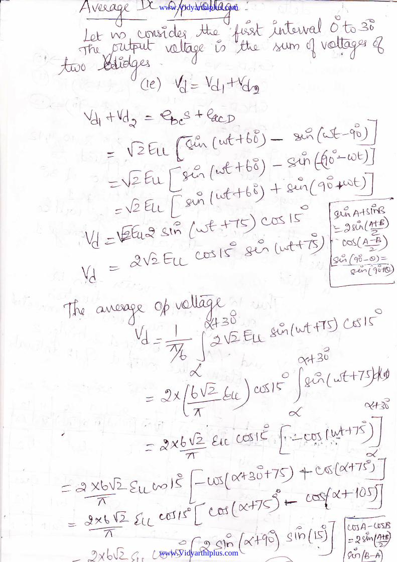
/rr ,,Yr, .rl*id# n" uUffim Wi''fi','ft^:o Mdgf^ o
0e) /4 = V4, W4u
- r^Getr (,*rt [-*'gt',
anroulx oh rd$ . oov,
- )- '^qil
eo 61"t+rl c-d r(
--% J- o(*Br' l- o l6:.f ;L+tf,t= J^ [u't' t") "stt )" \ .'
6-- / j "t+:3
N,tl.rrjl ))* o/f---- - - --l-
www.Vidyarthiplus.com
www.Vidyarthiplus.com
.. u
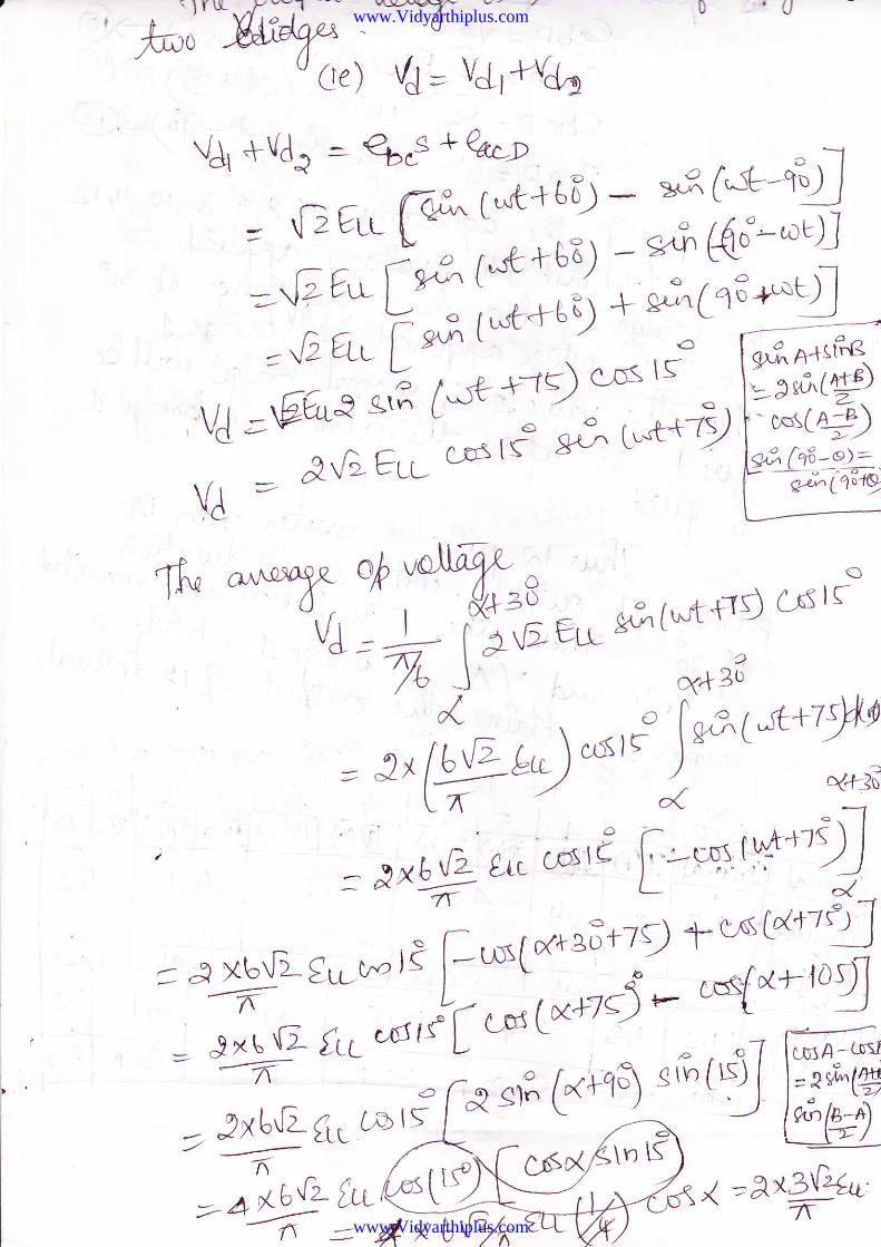
0e) /3= V4' Wgo
VJr +Vd.l =- €6"3 + QaLD
n (-tL49]
-{)€wlv^6) *n?,@d-"u).D ert(&l*t+::-;
olff
Foo
? [*€+bE
^tT *'"uff q - c,? (uft +-rg cs rroVJ- L i)rAEur r-- % J- q+ztl" o l*6 1;t+tSg
= 3N tgL")uslr )'*''*" **[r '" 4 ;
7t ;- -1
= J Xbrlz- €v-w,i [.--us[xtaS+t{) 1t''sv+tt1
ltn*(*nq\*c'sfx+-lofl--::=-
E -,,- /rr\ I I . ,^.. .?xr"(1 /tl edl\ L *' ,,> . .1 fffi;i
,;-"^t(.6'-El*(.-H"tgfffi{ = A xE{;4
www.Vidyarthiplus.com
www.Vidyarthiplus.com
- 6 ltC-e's lS -ctn lt :/+
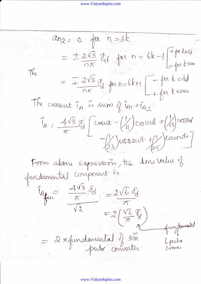
= *f+^) f"VA = &o-V&
,* P, ?k.kJfu*;u;n'ooo tk" hfr'Y c-r"':
ij*ry i#,ffi'b- r^*^d iffi ;l *,"-,,qrF{MH,ry'"*2 b'Yffi-eriu' u 'rsel !"'h rr*{
aYn""
^}n f:i,!rcu*.-ifuMfu"fi c.CI'*'hni^ fi,-fr.-i'+9 f- T=-""nbhr,tr'i
= ./xJs" f. .' lr--:t
.
= V(3) f6e =r'-b/tl1 w- e a e'l^ t 'lcYl= lr-tz-- \t 6 t.)/ \-
-ry5 5
J**- -\f O 1u, =4 (iur-f',
www.Vidyarthiplus.com
www.Vidyarthiplus.com
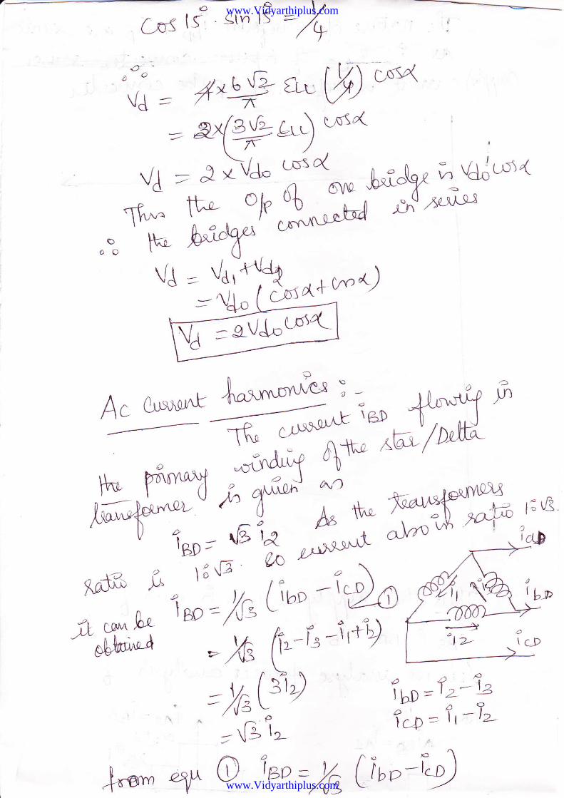
;t bp ! lc D qw Xa/\^-aW
Pfly a)""*^t uC a)"D
b ytrLr< ttwyvLlL,
-180' -120"
- o;}l@z"
120" 180"
'1.154 |d
o i".
0.577 ld
I
2.154|d
1 .577 ldID
a.5771"
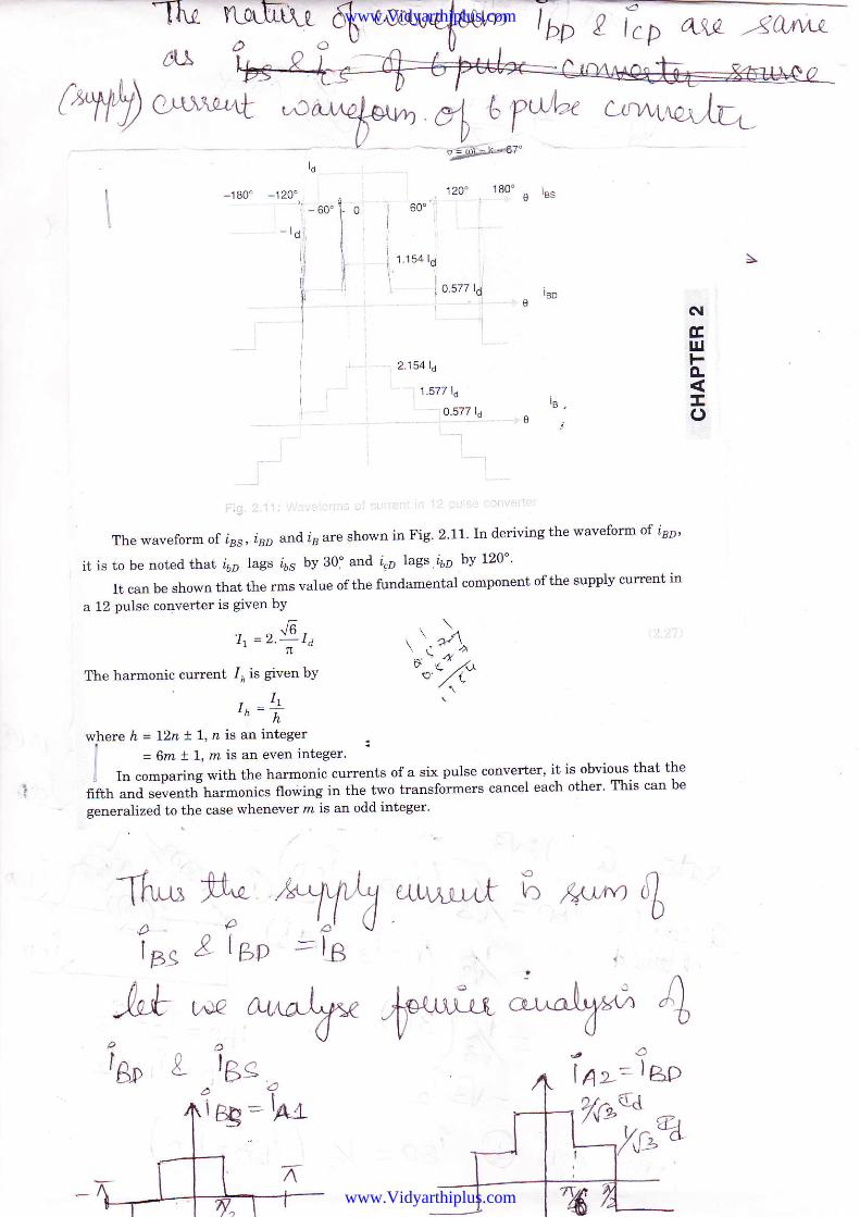
The waveform of ias, isr and is are shown in Fig' 2'11' In deriving the waveform of l3p'
it is to be noted that l6p lags i65 by 30i and i"p lags i6p by l2O''
It can be shown that the rms value of the fundamental component of the supply current in
a 12 pulse converter is given bY
, - r&,t|=z.-Id \ -t-\I _.r,The harmonic current /, is given by 'ot7(r. 1'-
,h - h
where h = l2n ! L, n is an integer
= 6m ! l, rn is an even integer.
i In co-ptring *ith the harmonic currents of a six pulse converter' it is obvious that the
fifth and seventh harmonics flowing in the two transforrners cancel each other' This can be
generalized to the case whenever m is an odd integer'
du
lgD
otGtu&!o
T- ry -V2 (Lu^jr"Lt 6 k"M IL
lns 8 lhp =lB
2^'b{a
-tttlB" L
A'o
BPa
I
;^*i*66
A I A>-=
t€
lgo
Frru
!. lcp qw
IO+\4--L^)x
U
Ea
:l&L
4.**"
'.^%.
www.Vidyarthiplus.com
www.Vidyarthiplus.com
a ^^-.4'^* %YffiW?*LqY^.*Y+ ':arrofueru"
AA {o'r""c aoq .,
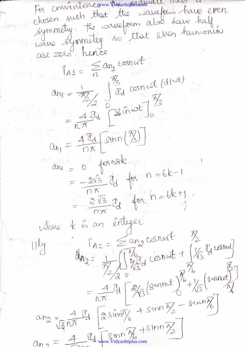
8f^tU:^^^'5,,""*D $ot g]"e4 lra".,**t^'
** *"* hrnj"q ' ' SanuwnxtIAL = VL ,-.4
\ ,1/s , ,A{d t*t)oru = h, \ a 'tn^"'*/; I - .n'&
4' ee ";sAtt J-'= ----.---
I
n-fl t-'-1,Tofg\hn
( ryrlorr t'6{l: \ -)
\
Alu - o ^ft*il r^ =ak-t= '--sG e {* r\
'----.-\(1\)
= "iga tr n=rkt-l '
o7a
r^{'\! , L e o'Y) ;nt'6r* ,p K)
t r[,t ' n ', u, = €-trtcsn^'rt T''d M^i'{trp^}-*:Wu*4
/:./so *"o*r;k*ryH
= #_ulr*to-hq = 4,ua [rr,'"d * Stnn
-*^q** G 6-" t ,L *, ---1
0r, " = +=9int." T'ntr"" /" \
www.Vidyarthiplus.com
www.Vidyarthiplus.com
=J-2Gt, h{ h=([-l fPu"azn Lc{ T-' ' L-i", a"-
= ; '1{t g, Je*r--6 Lnr f- f L odd
- ^,(
-d D [_* 4"i h e+snU
c-ruaortb ia e /<sLw) * T* frn,
Tfu
Tf,alft=
--7="-=-(r. :tvY
= &-x J }) s(n
,*.,fr"
www.Vidyarthiplus.com
www.Vidyarthiplus.com
lfu* a^r ,W"rL
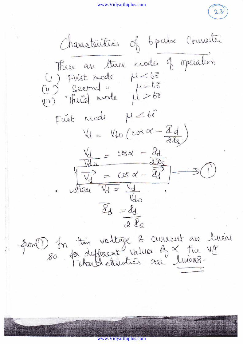
ct b.p.ul* Cr**^hU
^"*Ai" db ayu^f"+
L ) Purt ruodq H=us[,, { eaq!*d (r F: Uc
['i fir,bl r'^-"J'r H t h
-vJ; ld-VJ,c
A ==34--.-.}
'? gs
IQ
L Cu\r.r-iA Alr -luq"t\r^lar> A( ft',- v[,i^ ^"i -h^'Qqg
'
7 '- crrd- D4'
*;
Js. Al-p.lt
s-ou3
www.Vidyarthiplus.com
www.Vidyarthiplus.com
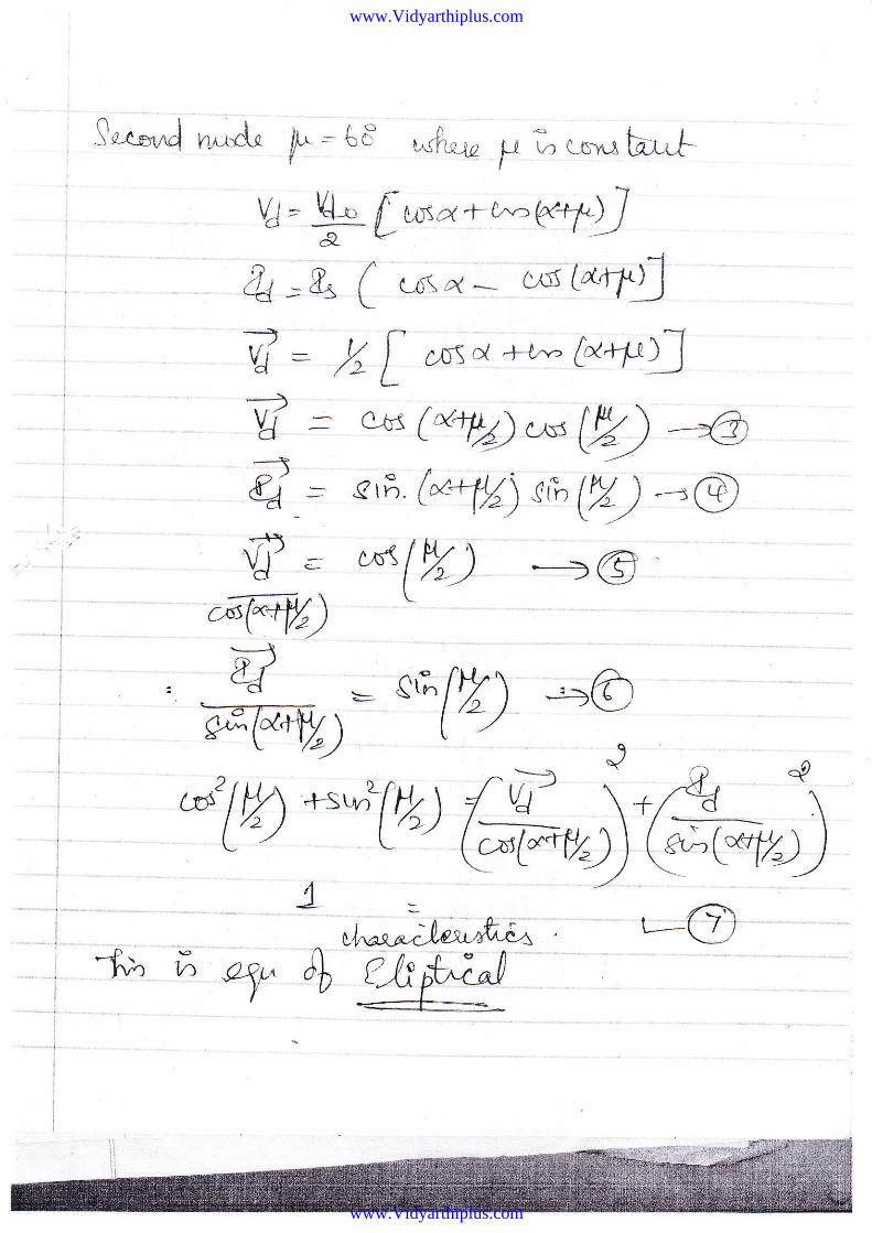
!"t*rd n^rtrU h - t.= *4*r, p ; t** ht F
U - !- [*o4-x]eq.D& '& ( ul-ret * tt$ (^q't;2_vJ - ,U L .,5S c{ &'-" t**fu\t: a6t(Nryr'*W) -gd = s6 (e+l|) rk (H) __.@
'f . xlW) -__) @c^l@) \
uW**U) ^ t-\ -d/ vJ- \+/ (
@err;;@4
\
D)
-f,E ;' *y
>-\y > eG[V\ _=@6W) (-/ --,
www.Vidyarthiplus.com
www.Vidyarthiplus.com
,4,jr1"eLtgt.--r Lt_+-VY\^, /t\r't7" €o
*T-lfis-u- a-to_
M.dt t' lt 3 AS4
1[") b<bt Jel va],-tr^r-T
I --u +l-,."phr , TLu c,cwur,td:Utis-n n*"{."(J r ,l
4 V.(6r-a;_9-,'-=C A -. \I "=#,r" --f Cb^;";aLh) Gt z i.q"r^ M Lt"= ZV -an ., - '6= 68-l,Y
, c
T,f:,W*trWyp*(- r\ o
r:#'6,ji ',-$
Jyt\-)
www.Vidyarthiplus.com
www.Vidyarthiplus.com
th^KA n,.oAo
u':r-ot ^e,. a&
VJ" (G cs lx-:E) -;#)
e-rE tol'o*tt) -ttw''85
V) }fff",c, ,.,p,r'&)LA Bt
4^ v; q?u1 oqil Jffits ,fu--
"\-u/ o\
,,,,;"\t. .*tt/ .-.,W \d.rt')t "
..u"/C V ,t\1)t----\ _ , cL
U;>
E
.\r/q^1z\i
?v;*A
B
(-
D
E
- E-&-------'---?.
*?l-d
,Og.>S
F/,rX^r/e{,)
V3
I
o-=/ s,rt1,
oe,C*:
N,
o
o
5o)^3\)
lg'
l-,.Otobb
6fp;lobo
www.Vidyarthiplus.com
www.Vidyarthiplus.com
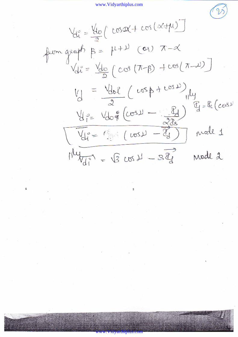
Vf=
t* T{V#=
9C rnrc+ '"'tc+t!p= yt+l C*,) n-4
q I c,.d tr-?) + wr (n-D)
t&L [ ,^=F * ,* u),,\
ti* @-l -- #) 'q=&(''o"Vt =a\
vJ i= J34Vg" (;' . f vosD *&r
r.^nd.t I
www.Vidyarthiplus.com
www.Vidyarthiplus.com
\1:1
\ ?4
l
I
{i: r
id
J'-ri'ut r'
| 1t:-1ii rI'i\
>lF
P
T- I\
\
i
.!)iI
.i. "? 'f tlrir*l rr.'r-/,ry,t1.',r. ,irri'r"rlr,r lrlr/rr /rir'rfir/ll r" {,'J: . 1, rurtixtlr" l',u:itir'r' ,;rlr! rrcqutivc tliltrt rtlItlgm tvit]r lrslrrrrt to llrc lr-;lrl-sf *r
111{'t r'1t{1.!Ifi Vtlll;t1.',t' ;tl. t'{r}.{ r'lrl'.r l, ;itllll r":tltttltlrrl;rtillg 'rnlt:lg*rr \t;llrr" { ur'l'r.'ni il. iJ lrrul iii r
rJ \ '. i I r (' ( r I I ! ( ' I r I rf, 11 ;rrrrl rii \'\
, r'\t \
,nst t,
www.Vidyarthiplus.com
www.Vidyarthiplus.com
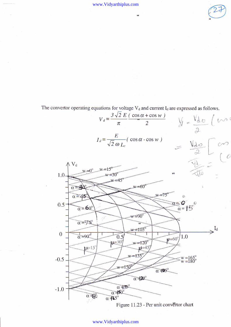
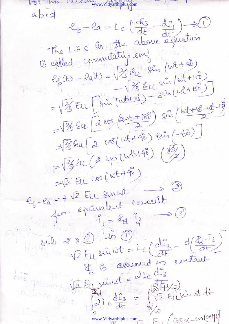
The Convertor operating equations for voltage Vd and cunent Id are expressed as follows.
sJjglcosa+cosw),o=----, - .\1 -
to=-!-( cosa-cos w /42 a 7,
vd_c { r...n r
r+
V"*,+
.-',i'!\?,.''./ j,{
/<)be
I c,,n>'l'-
( t,
Figure 11.23 - Per unit convEttor chart
www.Vidyarthiplus.com
www.Vidyarthiplus.com
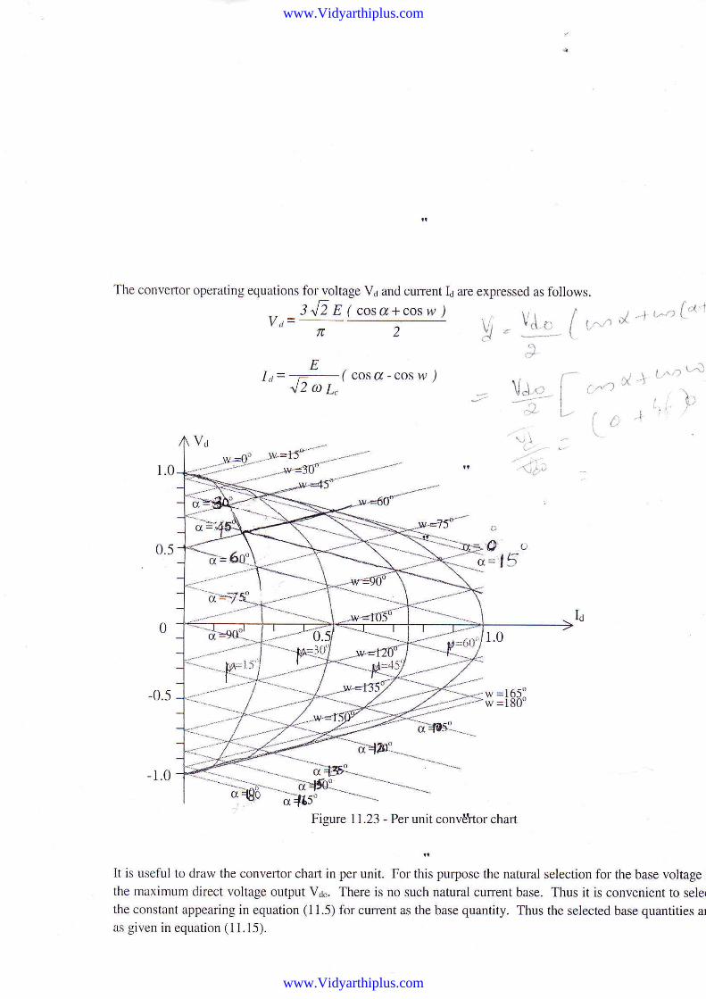
The convertor operating equations for voltage Vd and cunent Id are expressed as follows.
,, _3NE E ( cosa+cos w,)Y ,l -
- -'-,-ELt= _ -(
cosa-cosw.),l 2a7"
,1,.-,,{'^'
i..'1 L.'i)
' !'
\, \
1^.
r.t )
(t ,i
o
O' L,
a= t5
w =l 8O'
It is useful to draw the convertor chart in per unit. For this purpose the natural selection for the base voltage I
the maximum direct voltage output Vdo. There is no such natural curent base. Thus it is convenient to sele(
the constant appearing in equation (11.5) for current as the base quantity. Thus the selected base quantities ar
as given in equation ( 11.15).
Figure 11.23 - Per unit conv6ltor chart
www.Vidyarthiplus.com
www.Vidyarthiplus.com
64 wDc Potti'* r'ransmissinn Slstems'
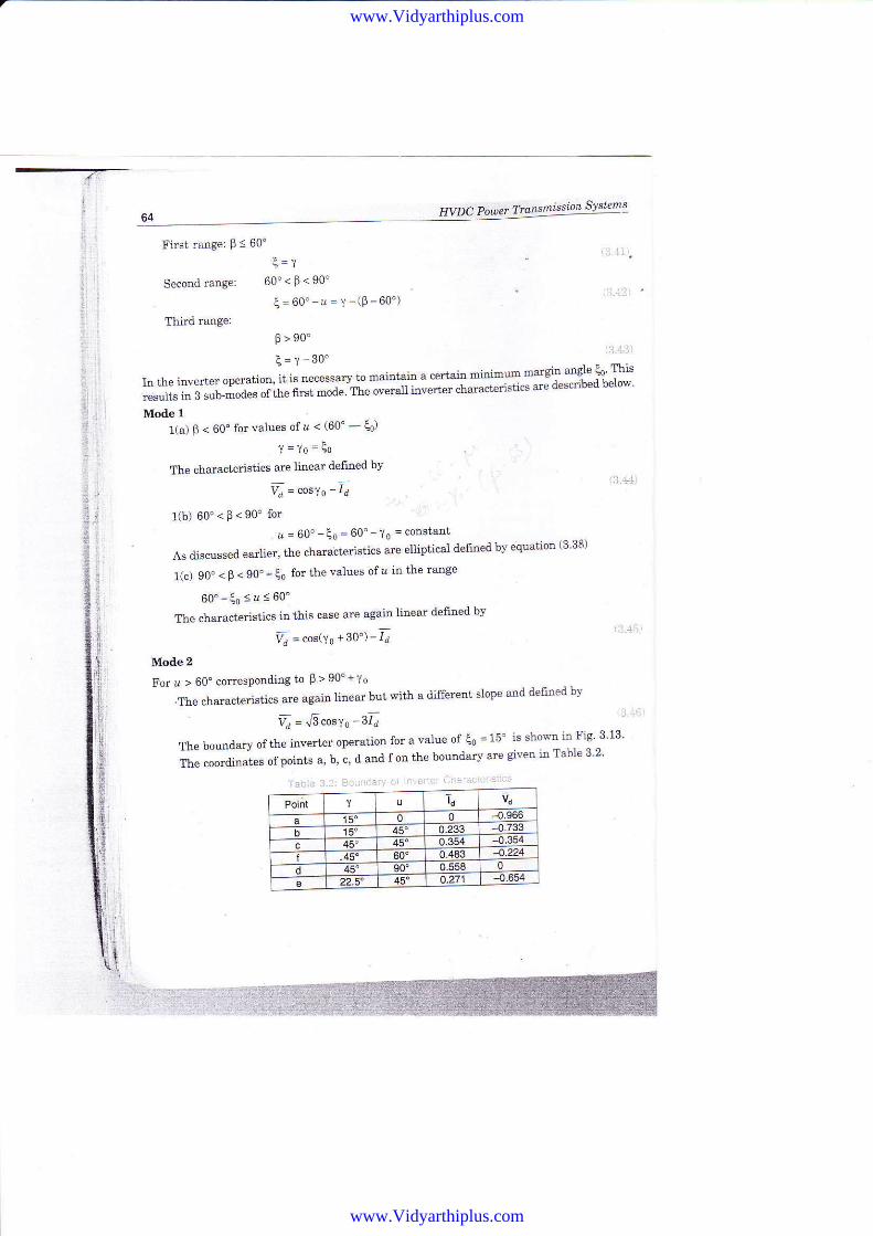
First range: P < 60" ,:t tf
F =\
Secondrange: 60"<F<90'
E=60'-11=y-(9-60')
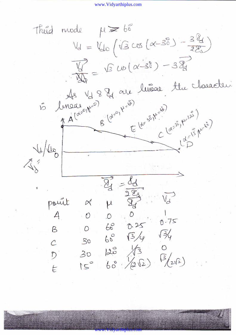
0t90"Third mnge:
E=Y-30' ljl.4il)
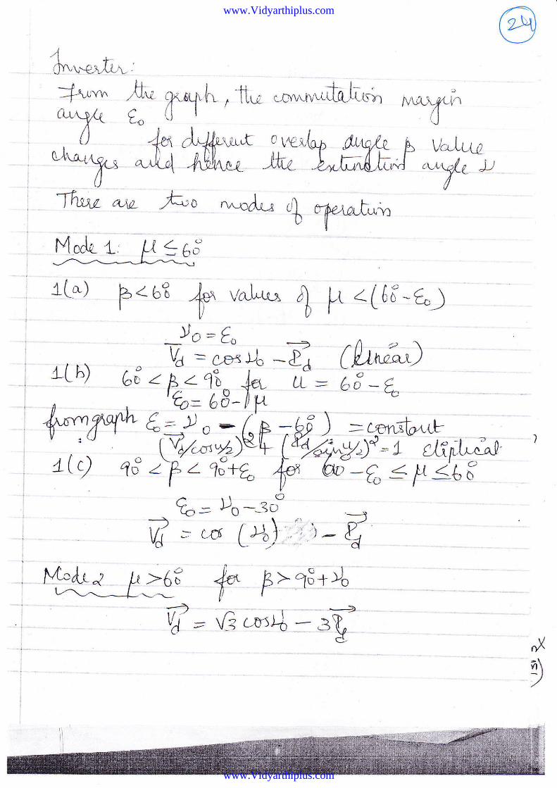
In the inverter operation, it is necessary to maintain a certain minim 'm margrn angle (1 This
results in 3 sub-modes ortrt" nt"t -oa" tt""oi""uili"#J"u"t"tl"ti"" "te described below'
Moile 1
1(a) F < 60'for values ofu < (60' - fu)
'Y=10=Eo
The characteistics aJe 'linear defined by
Y. = "o"10 -f
l(b) 60'<p<90'fora = 60'-Eo = 60'-10 = constaut
AsdiscuBsedearlier,thechara.ctensticsareellipiicatdefaedbyequation(3.38)
1(c) 90' < 0 < 90' + Eo for the values of 4 irl the range
60'-le<a<60'The characteristics iD this case are again liaear defined by
[ = cos(16 - 30'r- 16
Mode 2
For !, > 60" corresponditrg to P > 90'+10
,Thecharacteristrcsareagairlinearbutwithadifferentslopeaaddefiredby
[=.i5cos1o-3f
13.+.!l
r. !!'l
The boundary of the irverter operation for a value of t0 = 15' is shovn in Fig 313'
*" """*t"*" * nttutB a, b, c,
'l antl f otr the boundary are giver ia Table 3 2'
Talrle 3-i: ScLlrdaiv ci efle tI-rrc!;rsii"'
Point U td
a 15' o 0b 15. {c 0.3s4 4
t2-5. 450 o.27 .oi4
www.Vidyarthiplus.com
www.Vidyarthiplus.com
a
Slstems
\.r '.
le Q. Thisrcd below.
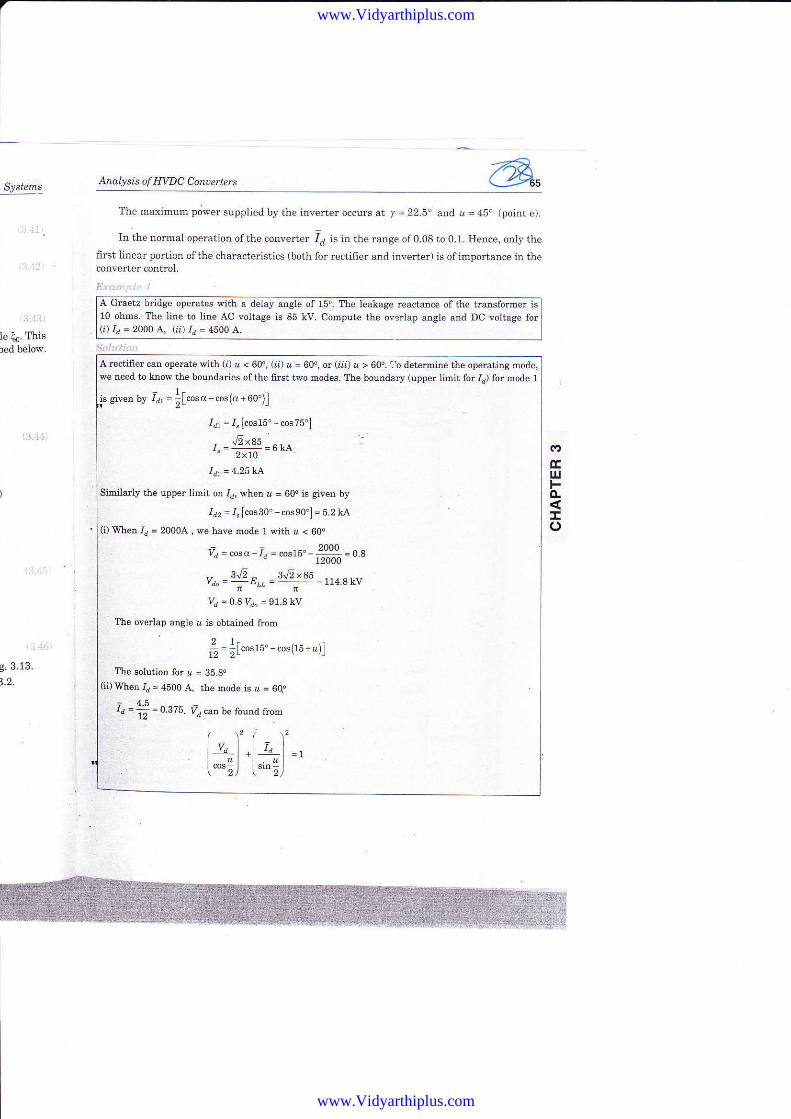
Analysis of HWC Conoerters @,The rna-ximum power supplied by the inverter occurs at y = 22.5. and. & = 450 (point e).
In the normal operation of the converter 14 is in the range ofO.08 to 0.1. Hence, only the
fiIst linear portion of the characteristics (both for rectifier and inverter) is ofimpodance in theconverter control,
E1.i :'.
A Graetz bridge operates s'ith a delay angle of 15". The Ieakage reactance of the transformer is10 ohms. I'he line to line AC voltag€ is 85 kV. Compute the overiap angle and DC voltage for(i) Ia= 2OOO A- (tr ld = 4500 A.
5.1. . .'
ril r Ie)ElrjFo-
!o
9.3.13.
A rectifier can operat€ with (;) a < 60", (ii) u = 600, or (t;) ' > 60". 1b determine the operatins mode,vre need to kaos' the boundades of the firct two modes. The bounalery (lpper limit for td) for mode 1
gi""" rr t = !["o"(,-cos(cr+oo')]
14 = d [cos15. -cos75"]
r-=f1!9-.po" 2x10
Idr = 4 25]cJ\
Similarly the upper limit or Id, when & = 60" is given by
Id, =i" [cos3o" cosso"]= 5.2lv\(i) When Ir = 2000A , we have mode 1 n ith z < 600
-- 2000Yd - cosq - // - cos ll)" -
2000 i U,a
v-=?Jt E" J'!E ' 85 tt+akvnftvd = 0.8 vdo = 91.8kv
The overlap angle u js obiained from'2lt,_-
, -;1"*t" cos{ls-& rl
Ih€ solution for L = 35.8"(ij) When /d = 4500 A. tbc Eode js d = 6qd
= 451d =i =0 375. Vd can be fouDd fiom
I l'r fv,),1"1_r- "l+ - "1=llcos I sin I. t 2) \ 2)
www.Vidyarthiplus.com
www.Vidyarthiplus.com
t, - rr .l937s I'lt"o"ro"=o.srsd L- I sD3o'r
I
Vd = 0 573xydo = 0 5?3x114 8= 65 8 kV
The 6riAg angl€ c is obtained ftom
v1=cosc-I,
"os o =V, + f, = O SZS +0 375 = 0 948
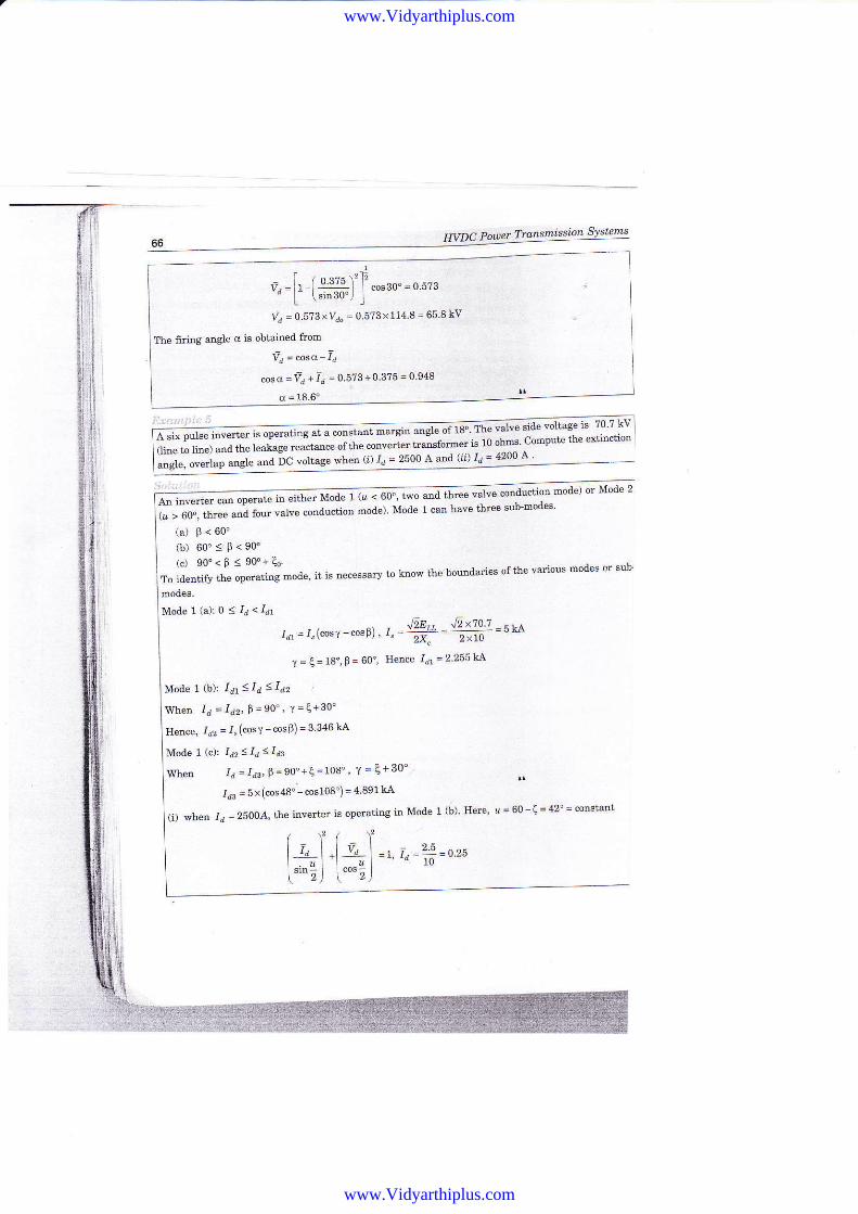
a six puse mverer rs u""""'"" " - """";;';;; o"l"r"'-"' * to "l-"- c.mput€ the extinction
(line to line) snd the l€alase reactance of the
;;;"*'i;;;iJ;.;c vortace wh€n (l rd = 2500 A ad r' -
(a) F < 60"
(b) 60"sP<90"(c) 90'< B < 90"+ q
To id€ntify the openting mod€' it is necessarj to know the bouldaries of the various modes or sub
Model(a):0<Id<Idt
rd, = /.(cosY ""'p1' r" @tt- hl:7r|;7 sue
r = €= 1s',p= 60'' n"o"" i =z zsst"L
e.r' irrn' ""-"* op".ut" io "i
no uoa" I o ' eo'' t*o(l/ > 60", ihree and folrl valve conductioD mode) Mode
1+1.[r"l=, r"'z]=ozs["'"rJ i"""t i
conduction mode) or Mode 2
Mode 1 (b): 1o'1 < ,Id < Id2
'ffien 1d =fdr,9=90", Y=e+30'
Hence, 16, = r" (cosv -cosB)= 3 346 kA
Mode 1 (c): Id, < Id < I,r3
When I, = Ids, P =90'+q =108', "/=e+30'Id3 = 5x(cos48" -€os108) = 4 891 LA
(i) when Id = 2500.4, the inverter is operatins in Mode 1 (b)- Here'',
= 60 -( = 42" = consiant
www.Vidyarthiplus.com
www.Vidyarthiplus.com
Analysis of EWC Conoet'ters
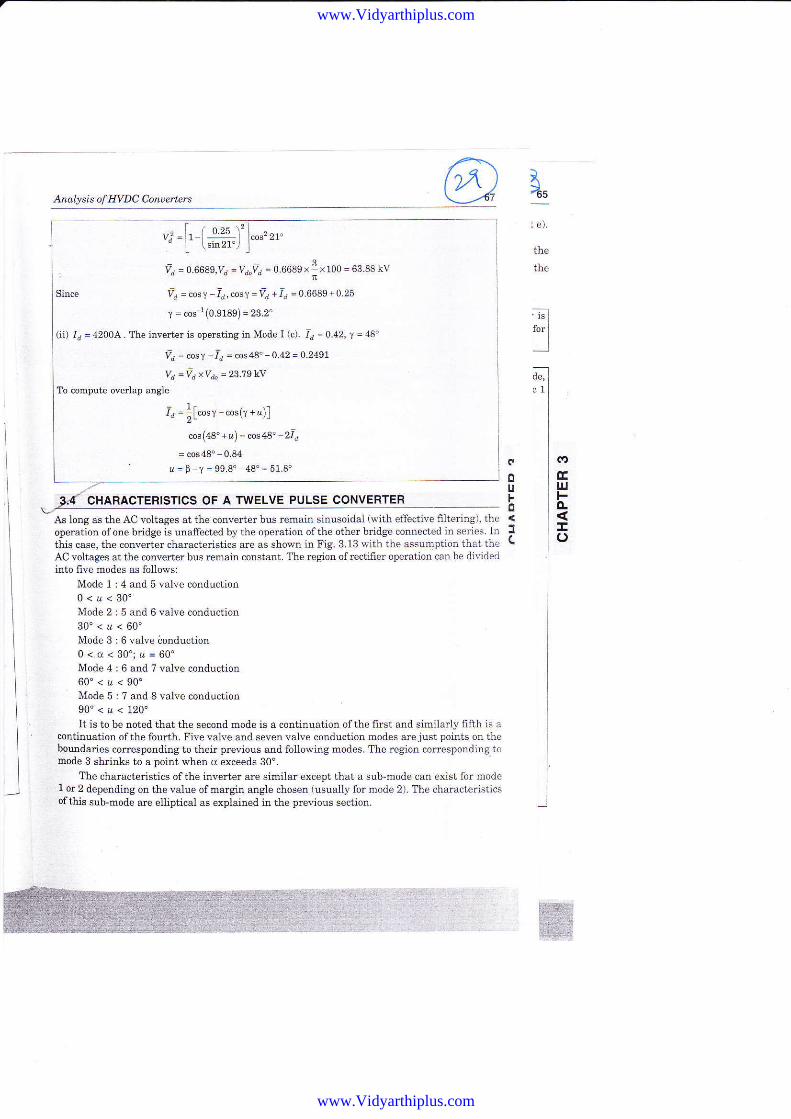
CHARACiERISTICS OF A TWELVE PULSE CONVERTER
As long as the AC voltages at tbe converter bus rcmain siDlsoidal ($ith effective filtering), theoperatror of oDe briclge is unafrect€d by the operation of the other bridge connected in series. Inthis case, the converter characteristics are as shown in Fig. 3.13.nith the assumption that theAC voltages at the converter bus re@ai4 cgnstsnt. ltre region ofrectifier operation can be dividealitrto five mocles as follows:
Mode 1 : 4 and 5 velve conaluction0<r<30"Mode 2 : 5 and 6 valve conduction30"<a<60"Mode 3 : 6 valve ionduction0<,d<30';&=60'Mode 4 : 6 and ? valve conduction
I4s
l e).
the
the
(a
Eu.tFo.
Io
o0uFo
JC
60"<u<90oMode 5 : 7 and 8 va.lve conduction90"<z<120"It is to be noted that the seconil mode is a continuation of the fimt atrd Bimilarly fifth is a
coBtinuation of the fourth. Five valve and se\€n valve conduetion modes are just poiDts on thebounalaries coresponding to their previous and followi g modes. The regron corresponding torBode 3 shrinks to a point when o exceeds 30'.
The characteristics of the inverter are similar except that a sub-mode can exist for mode1 or 2 depending on the value of margin angle chosen (usually for mode 2). The characterjsticsofthfu sub-mode are elliptical as explained in the previous section.
Vd - O.66A9,Vd -Vd.Vd - 0.6689I " \ 100 - 63 88 kV
% = cos 1 - id, cosr =vd +4 = 0.6689 + 0.25
T = cos 1(0.9189)= m.2"
(ii) Id = 4200A. The inv€rter is operating irx Mode I (c). 1d = 0.42, T = 48"
Va = cosf - -I, = cos4" - O.42 - O.249\
Va --id '<Vd"
= 2379kY
To coEpute ove ap angie
= t.I; = tlcos1 -cos(r - u)l
cos (4 8'- u) = cos {s" - 2 t= cos48"-0.84- r = B-Y = 99 8"-48'= 51.8'
www.Vidyarthiplus.com
www.Vidyarthiplus.com
I
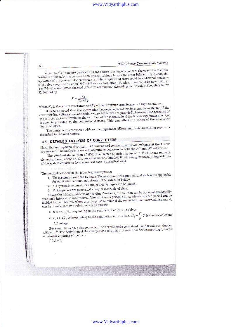
68 WDC Poaer Trdnsttfissidn Systems
WlrennoACfiltersareprovi'le'landtheso\ucereactanceisnotzerotf,reoperationofeitherbridge is affected b) the *-tutu"oo p'o"""t i"li"* oit"" i" t'ft" "ther
bddge ln this case tle
oDerat-ion oflhe lwelv" put." toot "t"t 'J"q-J-t" "ot-pti* ^oa tf'"t"
"ould be addidonal modes-
tit 5 valve cond+trion uoa u" o-i - s-; 'uli" """-i"i-tl"t iif er*' tttere could be new oode o[
5-6-7-6 valve conducLion rinstead ot o uaru-e col'J"6""i a"p""ai"g "" th" value of coupling factor
K defined bY
,, xs'' X..Xr
where Xs is the source reactance an'l X? is the converter traDsfor@er leakage reactance'
It is to be noted that the interact;n bgtwee ailjacent bd'lges -can
be Deglected if the
convelter bus voltages are sinusoidal tfienfC 0t1""" "" pto"ia"al' ffowever' the presence of
the sorrce reactance res,rlts in tle "aaatio'n "iir'" -tc"t*i" 9t
tle bus'voltage (udess voltage
control is proviileil at the converter "tutio"l fiti"""t" affect the shape of the converter
characteristicsThe analysis of a converter with source impedance' filterB and finite smoothing reactor is
described in the 1e:t section'
3.5 AILED ANALYSIS OF CONVERTERS
;--*""Jh" .""'*prio* or.0,,.r"o, Dc 'o"""t '"d::T:Tl'iTl"E*;:t:1-tr""::**i"'*Tl'tr,T iT'ii'l?$;"#;ffi ;";;;;;imf edances inboth the ic T1.",9 i:l*-":.11:
;ffi ;;ffi ;;;;"'i*".e"""i1"1,'111Er:;:l:il:",1*l,iTffiTffi ::1.e rleauJ'!!4!e ov' _"-" ': - rnear' A method for obtaiiing fast steady-stat€ i
eLements,lhe equal,ions sre also plecewlse
;; tili'";ffi il;;;;s for the-general case is 'lescribe'L
next'
The method is baseil oo the followilg assumptions:'^'"
i- *" ""*- * u*cribed by sets oflinear differential equations and each set is applicable
' r". p?tti"J^t .""a"ctioa pattern of the valves in bridge
' Z. l- "y"t"- i"
"1--etrical an'L source voltages are balanced-
3. Firing pulses are genera!€d at equal iotervals oftiroe
a#;:"'# ;;i"* ""u '"**
**ons' the solution canbe :t:*1"T:rfi:l:Grven tne ro'i'ra wuu""'- .-'-'-t'ii'tt"" ls per:iodic in steady-stat€' each period can be
over each interval or sub-interval The sr --, D^-L ;-+^-,-r i- mne"t
"'Tfi:;ci:r'ffffii:'JJi"iiiil"i",i"" tJ"";;"; orthe converter' Eachintervar' i4 seneral'
"rn t" aiulaia i"to t o sub-intervals as follows:
1. 0 < , < ,1, correspoBding to the coDduciiol of(m + 1) valves
2. li < t < ?r correspon dling to the cooduction of rz valves (! = 4 , ? is the period of the
p
AC voltage).
T'or example, in a 6-pu1se converter, ihe dorsal motle coasists of 3 aad 2 valve conduction
-*r'i'ji.tt" i"t*ti" "r
tm "t"tav-"itt" "olution
proceeils from first computitrg t' from a
non-linear equation of the form
f(t)=o'
l
ri
I
www.Vidyarthiplus.com
www.Vidyarthiplus.com

Anabtsis of INDC Converters
Orce ,l is obtained, the initial cotrditiods can be sets of linear algebraicequations. These equations are deriveil from bounddy conditions a"a "y"-"t
-, ""Ja";'"tr""".In geaerat, the following conshaints apply in dete;ining rhe boundart;;it;;".
1. Magnetic fluies and elect c charges must be coDtitruous fuDctions oftime.2. The current in th€ outgoing valve i6 zero at , = tr.
O3 r€!o p,'--!e iit tf ti-ie il.|eth9C {Dr lcst 9trad./.::-,a.ri4 iti.rilji!:It is already mentioned that there are two sub-inte.vals to be considered. Let the systen bedescribed by the fo]lorring stare equar ions.
ir(t) = lArlx 1ft) + lB lu1(r), 0 <, < ti2(.t) = lA;x2G) +LB2lu2G), tt <t <\
T'he -mders
ofthe state vectors xland,2 are D + 1 anal7? respectively, Since.the outgoing valvecurrent becomes zero at t = ,r, otre state var.iable is eliminated in the second sub,interval. ThesolutioaE ofthe above equations are:
rr(l) = ssl(t) + eal [.)c1(O) -x61(0)] r:..
,, " 2(t) = xs2?) + e4tta) 1y2 (tr ) _:r:s2 (4 )j
wherersr(t) is the forced rcsponse in sub_idterval;.There is no loss of generality in a.ssuming the current in the outgoing valve as ,i+1,superscript iadicates rhe (n + l)* variable in the vector:r,. Thus, *" 1ul,? '
*i*1(tl) = 0.+ Crr01) = 0'where C = [0 1] is a row veetor.
. - The vector rr2 (t) is the subset of the vector ,r (r) rllith the last variable removed fromrr(t). From the consideration of cootinuity i" tfr"
"tat" v""iall"", *;;"t
*-'
x2(t) = tI, :01er({) = trJrl(4)i'here 1, is the idetrtity matrix ofnth oftler. From consialerations of sJ,rrj@etry, we have
rr(0) = [SJr2{fi)''where S is a constant matrix of dioension (z +1) x r,.
The elernent ofthe matdx [s] can be o]taioed from the fonowiag considerations.1. The nC quantities are periodic with period 4. For exemple, the DC current ir, satisfiesthe relation
,"(0r. L(4)2. The AC quantities satisfir the following relations (assuming ?, = 1, ro is the system
angurar frequency) 3u
t"(0) = -x"(77)x6@) = -r,(71)x"l1) = -x6Tr)
GI
trIJJFAIo
www.Vidyarthiplus.com
www.Vidyarthiplus.com