naca arr l5f23
DESCRIPTION
Naca Arr l5f23TRANSCRIPT
23
.!
NATIONAL ADVISORY COMMITTEE FOR AERONAUTICS
ItrI RTIMI, RI: Pi)RTORIGINALLY ISSUED
August 1949 asAdvance Restricted Report L_23
LI_Z2_-_I_A_-_02_ VAIXIES OF THE DAMPII_
IN ROLL AND OF TEE PARAMETER USED IN
ESTINATII_ AILERON STICK FORCES
By Robert S. Swanson an_ E. LaVerne Pridd_V
Lam_ley Memorial Aeromautical LaboratoryLangley Field, Va.
, +"_TITUTE 0F TEPHI"C_ (J(Y
V
ACT
WASHINGTON
NACA WARTIME REPORTS are reprints of papers origlnally issued to provide rapid distribution of
advance research results to an authorized group requiring them for the war effort. They were pre-
viously held under a security status but are now unclassified. Some of these reports were not tech-
nically edited. All have been reproduced without change in order to expedite general distribution.
L - b_
NACA ARR No. LSF23 RESTRICTED
NATIONAL ADVISORY COMMITTEE FOR AEROF[AUTIC_
ADVANCE RESTRICTED REPORT
LIFTING-SURFACE-THEORY VALUES OF THE DANPING
IN ROLL AND OF THE PARAiv_ETER USED IN
ESTI_._ATING AILERON STICK FORCES
By Robert S. Swanson and E. LaVerne Priddy
An investigation was made by lifting-surfacetheory of a thin elliptic wing of aspect ratio 6in a steady roll by means of the electromagnetic-ana]ogy method. From the results, aspect-ratiocorrections for the damping in roll and aileron hingemoments for a wing in steady roll were obtained thatare considerably more accurate than those given bylifting-line theory. First-order effects of com-pressibility were included in the computations.
The results obtained by llfting-surface theoryindicate that the damping in roll for a wing of aspectratio 6 is 13 percent less than that given by lifting-line theory and 5 percent less than that given bylifting-llne theory with the edge-velocity correctionderived by Robert T. Jones applied. The results areextended rio wings of other aspect ratios.
In order to estimate aileron stick forces fromstatic wind-tunnel data, it is necessary to know therelation between the rate of change of hinge momentswith rate of roll and rate of change of hinge momentswith angle of attack. The values of this ratio werefound to be very nearly equal, within the usual accuracyof wind-tunnel measurements, to the values estimatedby using the Jones edge-velocity correction, which fora wing of aspect ratio 6 gives values 4.4 percent lessthan those obtained by liftlng-line theory. Anadditional lifting-surface-theory correction was
RESTRICTED
2 NACA ARR No. L5F23 -
calculated but need not be applied except for fairlylarge high-speed airplanes.
Simple practical methods of applying the resultsof the investigation to wings of other plan forms aregiven. No knowledge of liftlng-surface theory isrequired to apply the results. Yn order to facilitatean understanding of the procedure, an illustrativeexample is given.
INTRODUCTION
One of the many aerodynamic problems for whicha theoretical so]utlon by means of llfting-line theorymight be expected to be inadequate is the case of awing in steady roll. Robert T. Jones has obtained inan unpublished analysis similar to that of reference 1a correction to the lifting-l:_ne-tbeory values of thedamping in roll that an_ounts to an B-percent reductionin the values for a wing of a_pect ratio 6. Still moreaccurate values may be obtained by use of lifting-surfacetheory.
A method of estimating aileron stick forces in asteady roll from static wind-tunnel data on three-dimensional models is presented in reference 2. Thismethod is based upon the use of charts giving therelation between the rate of change of hinge moment with
rate of roll Chp and the rate of change of hinge
moment with angle of attack Ch_ in the form of the
IChpl which is determined by meansparameter"P'Ch !Ch ! '
of lifting-llne theory. It was pointed out in reference 2that the charts mlg_it contain fairly large errors whichresult from neglecting the chordwise variation invorticlty and from satisfying the airfoil boundary condi-tions at only one point on the chord as is done inlifting-line theory. A more exact determination of the
parameter _P)Ch is desired. In reference 3 an addi-
tional aspect-ratio correction to Ch_ as determined
from lifting-surface theory is presented. In order
to evaluate the possible errors in the values of _I(_P_Ch
NACA ARR No. L5F23 3
as determined by lifting-line theory, it is necessaryto d_termine similar additional aspect-ratio corrections
to Chp.
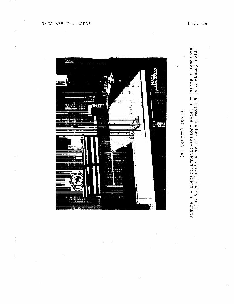
A description of the methods and equipment requi_edto solve lifting-surface-theory problems by means ofan electromagnetic analogy is pre_ented in reference 4.An electromagnetic-analogy model simulating a thinei]iptic wing of aspect ratio 6 in a steady roll wasconstructed (fig. !) and the magnetic-field strengthsi_iulating the induced downwash ve!ocities was measuredby the methods of reference 4. Data were thus obtainedfrom which additional aspect-ratio corrections to Chp fora win_' of aspect ratio 6 were determined.
Because of the small magnitude of the correction
to _i(_P_Ch introduced by the lifting-surface calculations,it was not considered worth while to conduct furtherexperiments on wings of other plan for_s. An attemptwas therefore made to effect a reasonable generalizationof the results from the available data.
Inasmuch as the _heory used in obtaining theseresults is rather complex and an understanding of thetheory is not necessary in order to make use of theresults, the material presented herein is convenientlygiven in two parts. Part I gives the results in aform suitable for use without reference to the theoryand part II gives the development of the theory.
SYMBOLS
(Z
c I
C L
Ch
C_
angle of attack (radians, unless otherwisestated)
section lift coefficient _-_ ./
wing lift coefficient _--_--/
hinge-moment coefficient /Hinge moment_
\\ q_a2ba /
_Rollin C momen t_rolling-moment coefficient \- qSb /
4 NACA ARR No. LSF23
a o
pb/2V
F
C7,-p
Chp
Ch_
CI,a
(_P) Ch
C
CS
cb
Ca
Ca
x
Y
ba
b/2
slope of the section lift curve for incom-pressible flow, per radian unless otherwisestated
wlng-tlp helix angle, radians
circulation strength
damping coefficient; that is, rate of chaPgeof rolling--moment coefficier_t with rate
of roll (Tp_-2_ j
rate of change of hinge moment with rate of
roll _ _ Ch _, (pb,/_ _I)
rate of change of hir,ge moment with angle of
attack k,,_"a,'-,}
rate of change of wing lift coefficient
with angle of attack \_--_--/Cho__absolute value
of the ratio _ h_)
wing chord
wing chord at. plane ofsymmetry
balance chord of aileron
chord of aileron
aileron root-mean-square chord
chordwise distance from .wing leading edge
spanwlse distanca from plans _f s_etry-
aileron span
wing semi span
NACA ARR No. I:SF}93 8
S
W
Fs
8s
6a
A
Ac
k
M
W
V
q
E
E'
F
area of wing
weight of airplane
stick force, pounds
stick deflection, degrees
aileron deflection, degrees, positive downward
aspect ratio
eq_ivalemt aspect ratio in compressible
taper ratio, ratio of fictitious tip chordto root chord
free-stream _lach n_ber
vertical component of induced velocity
free-stream velocity
edge-velocity correction factor for lift
edge-velocity correction factor for rollingmoment
hinge-moment factor for theoretical loadcaused by streamline-curvature correction(reference 5)
experimentally determined reduction factor for
¢
8
KI, K2 constants
Subscript 8:
LL lifting-llne theory
F to include effects of viscosity
trailing-edge angle, degrees
parameter defining spanwlse location
6 NACA ARR No. LSF23
LS
EV
SC
max
o
i
e
c
llft_ng-surface theory
edge-velocity correction
streamline curvature
maximum
outboard
inboard
effective
compressibility equivalent
I-APPLICATION OF METHOD TO
STICK-FORCE ESTIMATIO[(S
GENERAL METHOD
The values of the damping in roll C_p presented
in reference 2 were obtained by applying the Jonesedge-velocity correction to the lifting-line-theoryvalues. For a wing of aspect 6, the Jones edge-velocity
correction reduces the values of C_p by about 8 percent.From the data obtained on the electromagnetic-analogymodel of the elliptic wing of aspect ratio 6, a moreaccurate correction to C_ for this aspect ratio
Pcould be calculated. The damping in roll was foundrio be 13 percent less than that given by llftlng-linetheory. The results were extended to obtain values
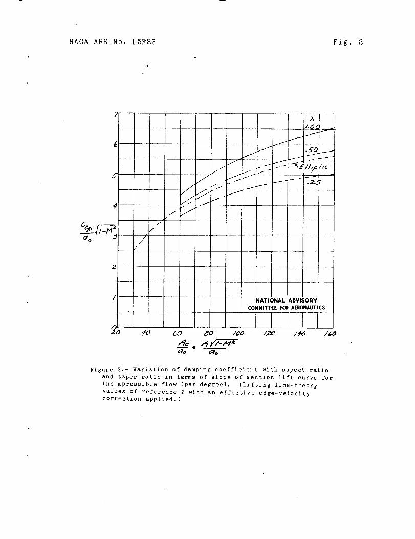
of C_p for wings of various aspect ratios and taperratios. These values are presented in figure 2. The
parameter \/1 - M2 is included in the ordinates andabsciss_to account for first-order compressibility
effects. The value of ao to be used in figure 2
is the value at M = O.
The method of estimating aileron Stick forces
- .requires the use of the parameter P Ch
Because Cha can be found from the static wind-tunnel
data, it is possible to determine Chp and thus the
effect of rolling upon the aileronstlck forces
(a) is known. In order to avoid measuring ,Chaif p Chat all points to be computed, the effect of rolling isusually accounted for by estimating an effective an_:leof attack of the rolling wing such that the statichinge moment at this angle is equivalent to the hingemoments during a roll at the initial angle of attack.The effective angle of attack is equal to the initialangle of attack corrected by an incremental angle (A_)Ch
that accounts for rolling, where
The value of (A_)Ch is added to the initial a for
the downgoing wing and subtracted from the initialfor the u_going wing. The va_nes of Ch correspondingto these corrected values of a are then determinedand are converted to stick force from the known dynamicpressure, the aileron d_mmnsion_, and the mechanicaladvantage.
The value of pb/2V to be used in equation (1)
for determining (Aa) ch is (.-.asexplained in reference 2)the estimated value fok" a rigid unyawed wing; that is,
f_
2V- C_p
The value of C_ to be used in Calculating pb/2Vshould also be corrected for the effect of rolling.The calculation of pb/2V is therefore determined bysuccessive approximations. For the first approxi-mation, the static values of C_ are used with the
from figure 2. From the f_r_t-approzi-value of C_pmation values of pb/2V, an incremental angle of
attack (Aa) c_ is estimated. For all practical purposes,
(ap) c_ : (aP)Ch
8 VACA ARR ?[o. LSF23
and from equation (i),
(A_) C_ _= (C_P)ch _V
Second-approximation values of C_ can be determinedat the effective angles of attack _ + As and _ - Aa.The second-approximation value of pb/2V obtained fromthis value of C_ is usually sufficiently accurateto make further approximations ur_ecessary.
In order to estimate the actual rate of roll,values of pb/2V for the rigid unyawed wing must becorrected for the effects of wing flexibility andairplane yawing motion. A_n emf:irical reduction factorof 0.8 has been suggested for use when data on wingstiffness and stability derivatives are not availableto make more accurate corrections. Every attempt shouldbe made to obtain such data because this empiricalreduction factor is not very accurate - actual valuesvarying from 0.6 to 0.9. The improvement in the
theoretical values of C_ obtained by use of lifting-surface theory herein is _ost if such an empiric_l" factoris used. In fact, if more accurate corrections forwing twist and yawing motion are not made, the empiricalreduction factor should be reduced to 0.75 when the more
correct values of C_p given in figure 2 are used.
(_) presented in reference 2The values of p Ch
were obtained by graphically integrating some publishedspan-load curves determined from lifting-line theory.Determination of this parameter by ....me_h_ of the lifting-surface theory presented herein, however, gives somewhatmore accurate values and indicates a variation of the
parameter with aspect ratio, taper ratio, aileron span,F_.
Mach nu_.ber, CI_ , and the parameter (Oa/c In practice, a value of (_ equal to the
lifting-line,theory value of (_p) n_ _ appendix)",. t' _._T _.j
times the ,7ones edge-velocity correc_lon
parameter Ac + 4 AcE c + 2 is probably sufficientlyAc + _ AcE' c + 4
accurate. The incremental angle of attack (Aa)Ch is then
NACA aPJ< Ho. L5F23 9
2b(Aa)Ch = _V _ _/ChEv
(_p) Ac ÷ 4 AcE c + 2 i_b (2)= ChLI ' A-_C+----_ AcE' c + 4 2V
If furt_-er refiner lent in estimating the stick forceis desired, a small additional lifting-surface-theory
= (C) _ may be added to thecorrection ACh & hp L3
hinge moments determined. For wings of aspect ratios offrom about 4 to 8, values of this additional lifting-surface-theory correction are within the usual accuracyof' the r,_easuremenfis of hinge moments in wind tunnels;that is,
) ob -AC h = A hp LS _ 0.002
for a pb/2V of 0.i and therefore need not be appliedexcept for very accurate work at high speeds on large
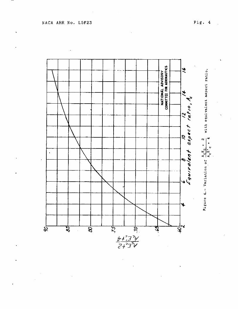
(p) Ac + 4airplanes. Values of _ ChL L Ac + 2 are given in
figure 3. The effective aspect ratio Ac -- A¢l - M 2is used to correct for first-order compressibility effects
and values of AcEc + 2+ _. are given as a function of A cAcE' c
in figure 4. Values of the correction
Ica c _I - M 2,,/)2a (Chp) LS Fn
are given in figure 5 as a function of Ac, and values
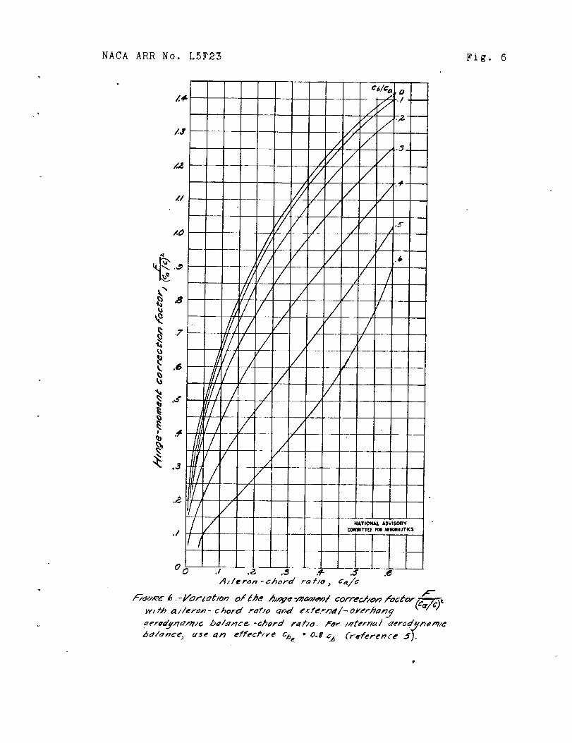
of F are given in figure 6. The value of _ is(Ca/C) _
approximately I - 0.0005_. The values of Cb/Ca givenin figure 6 are for control surfaces with an externaloverhang such as a blunt-nose or Frise overhang. Forshrouded overhangs such as th6 internal bal_ce, thevalue of Cb/C a should be multiplied by about 0.8 beforeusing figure 6.
If the wind-tunnel data are obtained in low-speed
w_nd tunnels, the estimated values of C_p and --.C_P_Chshould be determined for the wind-tunnel Macb ntm,lber
I0 _,ACaAR_ i_o. =_'_
(ass_me M = 0). Otherwise the tunnel data must becorrected for compressibility effects and presentmethods of correcting tunne_ data for compressibilityare believed unsatisfactory•
±._._,o_,l_ _, = EX_,IPLE
Stick forces are computed from the results of thewind-tunnel tests of the 0.40-scale semispan model ofthe wing of the sa_e typical fighter airplane usedas an illustrative example in reference 2. Becausethe wlnd-tumuel data were obtained at low speed, nocorrections were applied for compressibility effects•Because this example is for illustrative purposesonly, no computations _:ere made to determine the effectsof yawing motion or wing twist on the rate of roll butan empirical reduction factor was used to take acco_utof these effects.
A drawing of the plan form of the wing of the modelis presented in figure 7. The computations are made atan indicated sirspeed of 250 miles per hour, whichcorresponds to a lift coefficient of 0.170 and to anangle of attack of 1.3 ° . The data required for thecomputations are as follows:
Scale of mode] ................... 0.40Aileron span, ba, feet ............. 3.07Aileron root-mean-square chord _a, feet . . . 0.371
Trailing-edge angle, _, degrees ........ 13.5
Slope of section lift curve, f e .ao, per de r e 0.094
Balance-aileron-chord ratlo, Cb_C a ...... 0.4Aileron-chord ratio, Ca/C, (constant) ..... 0.155
Yi 0.58Location of inboard aileron tip, _ ......
Y____o...... O• 98Location of outboard aileron tip, b/2Wing aspect ratio, A ............... 5.55Wing taper ratio, k .............. 0.60
Iffaxlmum aileron deflection, 6area x, degrees .... +16
Maximum stick deflection, eSmax, degrees ..... ±21Stick length feet 2 O0Aileron-linkage-system ratio ............ l:lWing loading of airplane, W/S, pounds per
square foot .................. 27.2
NACA ARR No. L5F23 II
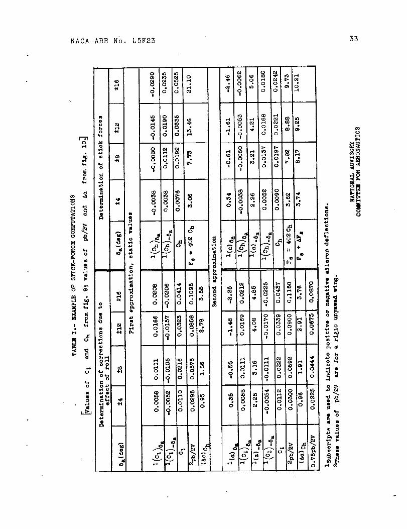
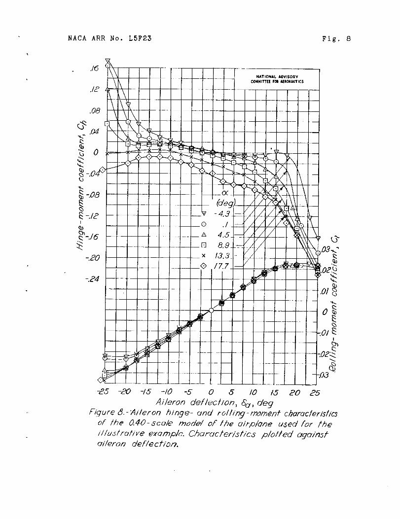
The required wind-tunnel te_t results includ_rolling-moment coefficients and hlnge-moment coefficientscorrected for the effects of the jet boundaries. Typicaldata plotted against aileron deflection are presentedin figure 8. These same coefficients cross-plottedagainst ansle of attack for one-fourth, one-half, three-fourths, and full aileron deflections are given infJgure 9. The value of Czp/a o as determined fromfigure 2 is 4.02 and the value of C_D is 0.$78. The
Ac + 4 AcV__C +value of 1 \
Ac Ac ' + 4 used in equation
Chi=L "_ c
to determine (Aa)Oh is found from figures 3 and 4 to
be 0.565 and is used to compute both the rate of roll andthe stick force.
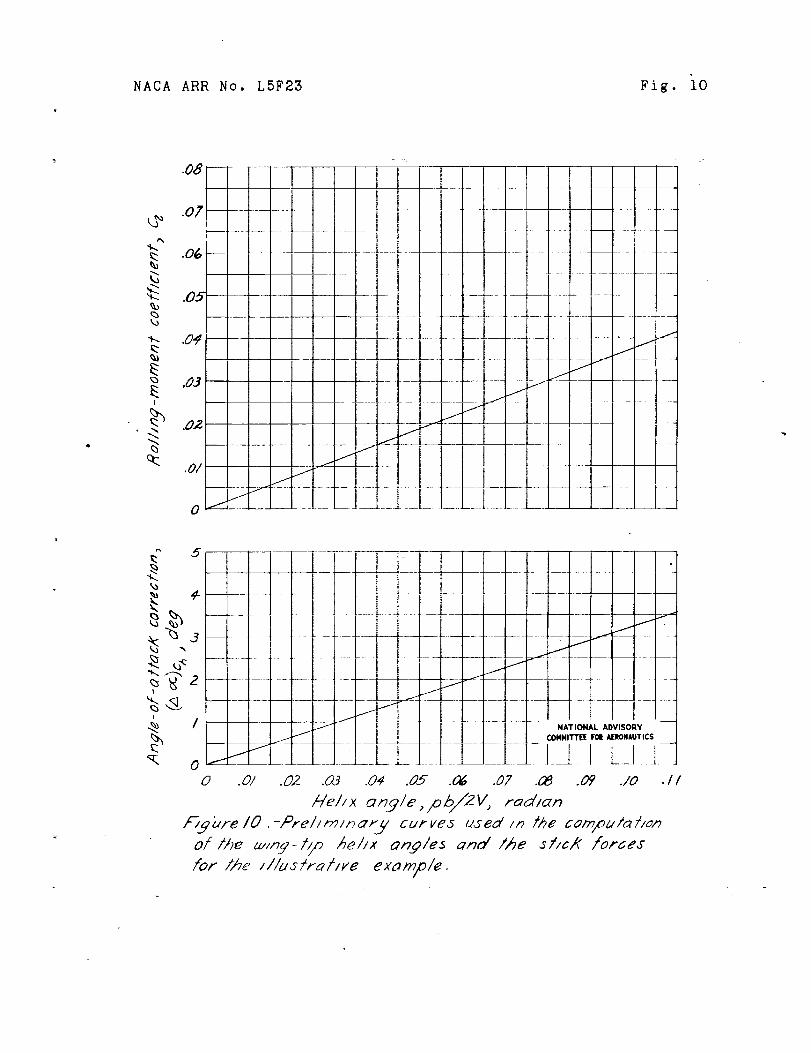
In order to facilitate the computations, simultaneous
plots of C_ and (Aa)Ch against pb/2V were made
(fig. lO).
The steps in the computation will be explained indetail for the single case of equal up and down a__lerondeflections of 4o:
(I) From figure 9, the valuesof C_ correspondingto 6a = 4 ° and 5a = -4 ° at _ = 1.3 ° are 0.0058
and-0.0052, respectively, or a total static C_of 0.0110.
(2) A first approximation to
value of pb/2V correspondin_ tofigure i0 is found to be 0.95 u.
(A_)Ch taken at the
C_ : 0.0110 in
(3) Second-approximation values of C_ (fig. 9)are determined at _ = 0.35 ° for 8a : 4 ° and at a = 2.25 °for 6a=-4 ° , which give a total C_ of 0.0112.
(4) The second approximation to (A_)Ch is now
found from figure i0 to be 0.96 ° , which is sufficientlyclose to the value found in step (2) to make any additionalapproximations unnecessary.
12 NACA ARR No. L5F23
(5) By use of the value of C_ from step (3!, thevalue of pb = 0.0300 is obtained from figure I0.
2V
(6) From figure 9 the hinge-moment coefficientcorresponding to 8a = 4 ° and the corrected angle of
attack c = 0.34 ° is -0.0038 and for 6a = -4 °and _ = 2.26 ° is 0.0052. The total Ch is there-fore 0.0090.
(7) The _tick force in pounds is calculated fromthe aileron-linkage-system data, the aileron dimensions,the increment of hi_ge-momemt coefficient, and the liftcoefficient as follows:
Stick force × Travel : Hinge moment x Deflection
., a_a2wmere the hinge moment _.s equal to Chqb and the
motion is linear.
Substitution of the appropriate values in the
equation gives
2 x 21 _ 16 Chqba_a2F s -S_fUg-o - 5-_?T_ , .
and the wing loading is
W= qC L
= 27.2
Therefore,
_ o. ].6 x 57.32--x--__
or
ChF_ = 68.4
CL
Thus, when Ch = 0.0090 and CL =
O. 0090F s = 68.4 x -_
O. 170,
= 3.62 pounds
}{ACA ARR I,_o. I:5F23
Th_ ctlck t, rce _• o _s that due to a_]eron deflection andhas been corrected by (Cp\ as de%ermi_:_d with the
_:VJones edge-'_e!oc_ty correction applied to the liftin_._-l].ne-theory value.
(S) The small additlonsl lift!ng-surface correctionto the h._nge moment (fig. 5) is obtained from
--(__ = O.Of]07A (Chp_ LS F_I
and since _ : 13.50,
_ : i - 0.0005(!3,5) _°
= 0.91
From f_gure 6,
Therefore,
F
LS
= 0.0207 x O.91 x 0.5,5
= 0.0i03
a_d
" Ch E,_ : O.flO,_ × 0.03
: O. 000[5
(9) The AF s due to the add itioi_la! lifting-
surface correct'on of step (8) m_y be e_"pressed as
AFs = 0.170 A h LS
: 0.L94 pound
14 ,N_CA ARR No. L5F_
Then,
Total stick force = F s + _F s
= 3.62 + 0.124
= 5.74
The stick-force computations for a range of ailerondeflection are presented in table I. The final stick-force curves are2resented in figure I] as a function ofthe value of pb/2V calculated for the rigid unyawedwing. For compari._on, the stick force_ (fir_t-approxlmationvalues of table I) calculated by neglecting the effectof re!ling are also presented. .Stick-force characteristicsestimated for the flexible airplane with fixed rudderare prese_ted in figure Ii. The va!uos of pb/2V obtainedfor ths rigid unyawed wing were simpl?_ reduced by applyingan empirical factor of 0.75 as indicated by the approxi-mate rule suggested in the preceding section. No calcu-lations of actual wing twist or yaw and yawing motionwere made for this example.
II - D E V E L 0 P "_IE N T O F _,_[E T H 0 D
The method for determining values of C_p and Chp
is based on the theoretical flow around a wing in steadyroll with the introduction of certain empirical factorsto take account of viscosity, wing twist, and minoreffects. The theoretical solution is obtained by meansof an electromagnetlc-analogy model of the liftingsurface, which simulates the wing and its wake by current-carrying conductor._ in such a manner that the surroundlr,_magnetic field corresponds to the velocity field aboutthe wing, The electromagnetlc-analogy method of obtainingsolutions of lifting-surface-theory problems is discussedin detail in reference 4. The present calculations werelimited to the case of a thin elliptic wing of aspectratio 6 rolling at zero angle of attack.
NACA ARR No. LSP23 15
•_ r_ _' G': ,'r _T TEL._C._RO=_A _,_T_.C-A,,_A._0GY MODEL
Vortex Pattern
In order to construct an electromagnet!c-analogymodel of the rolling w_ng and wake, it is necessaryto determine first the vortex pattern that is torepresent the rolling wing. The desired vortexpattern is the pattern calculated by means of thetwo-dimensional theories - tDin-a!rfoil theory andlifting-line theory. The additional aspect-ratiocorrections are estimated by determining the differencebetween the actual shape of the wing and the shape thatwo_11d be required to sustain the lift distribution orvortex pattern determined from the two-dimensionaltheories•
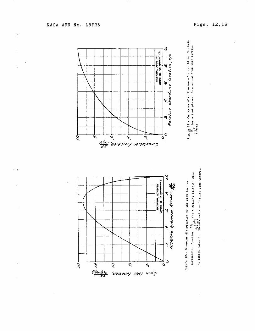
For the special cases of a thin elliptic wing ata uniform ancle of attack or in a steady roll, thelifting-line-theory values of the span load distributionmay be obtained by means of simple calculations (refer-ence 6). The span load distributions for both casesare equal to the span load distributions determinedfrom strip theory with a uniform reduction in allordinates of the span-load curves by an aerodynamic-
induction factor This factor is _A• _ _ for the wingA
at a uniform angle of attack and _ for the wing in
steady roll• The equation for the load at any spanwise
station _Z_ of a thin elliptic win S at zero angle ofb/2
attack rolling steadily with unit wing-tip helix anglepb/2V is therefore (see fig. ].2)
c c_ 2wA 1 - (3)o (pb/2v)= ;, + 4 /
_here ao = 2_.
16 ]_TACAARR l[o. LSF23
2F _ I
cc_V w
whe re x/c
The chordwise circulation fumct_on 2Fcc _V
airfoil theory for an inclined flat plate is
is measured from the leading edge.
fig. 13 for values of 2r .)cc_V
!
The vortex pattern is determined from lifting-line theory as the product of the spanwise-loading
ccfunction _ and the chordwise circulation
cs (pb/2V)-
function 2pfor all points on the wing and in the
from thin-
(4)
wake; thus,
2r
csv(pb/2v)cc t 2P
os(pb/ v) oc V
Contour lines of this product determine the equivalentvortex pattern of the rol_ing wing. Ten of these linesare shown in figure 14. The contour lines are givenin terms of the parameter
2P
c sV ( pb/2V]
[csv(pb/2v)]F
which reduces to._11aX
Construction of the Nodel
Details of the construction of the model may beseen from the photographs of figure i. The tests weremade under very nearly the same conditions as were thetests of the preliminary electromagnetic-analogy modelreported in reference 4. The span of the model was
'..'ACAARR No. L_F23 17
twice that of the model of reference 4 (6..56 ft Jr steadof 3.28 ft), but since the aspect ratio is twice aslarge (6 instead of 3), the maximum, chord is the same.
In order to simplify the construction of the model,only one semispan of the vortex sheet was simulated.Also, in order to avoid the large concentrations ofwires at the leading edg_e and tips of the wing, thissemispan of the vortex sheet was constrrcted of twosets of wires; each of the wires in the set reprezentingthe region of high load grading s_mulated a larger
than the wires in the setincrement of A *._S__' _a_representing the regzon of low load grading.
Downwash _easurement s
The magnetlc-field strength was measured at 4 or 5vertical heights, 15 spanwise locations, and 25 to 50chordwise stations. A nuJ._ber of repeat tests were madeto check the sccurscy of the measurements and _atisfactorycb.ecks were obtained.
The electric current was run through each set ofwires sepa:mtely. With the current flowing through oneset of wires, readings were taken at points on the modeland at the reflection points and the s_m of these readingswas multiplied by. a constant determined from the increment
of vorticity _ --_._ _ represented by that set of wires\ max / , ,Them, with the current flowing through the other se_ ozwires, read__ngs were taken at both rea] and reflectionpoints and the sT.amof these readings was multiplied bythe appropriate constant. The induced downwash was thusestimated from the total of the four readings. The factthat four separate readings had to be added together didnot result in any particular loss in accuracy, becausereadings at the missing semispan were fairly snail andless influenced b v local effects of the incrementalvortices. A more accurate vortex distribution was madepossible bTf using two separate sets of wires. The measureddata were faired, extrapolated to zero vertical height,
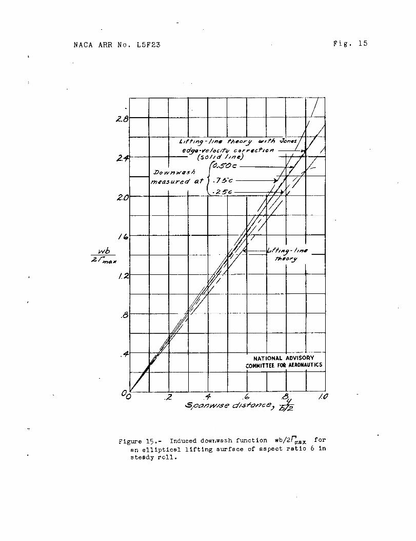
wb as dis-and converted to the downwash function _fma x
wbcussed in reference 4. The final curves of _ are
18 ITACAARF No. LSF23
presented for the quarter chord, half chord, and three-quarter chord in figure 15. Also presented in fi_ure 15
wbare values of _ calculated by llfting-line theory
maxand values calculated by lifting-llne theory as corrected
by the Jones edge-velocity correction.
DEVEZOP_ENT OF FORMULAS
General Discussion
Lift!n____zsurface corrections.- The measurements ofthe m_-Cic_T_!d so_ength (induced downwash) o _ theelectromagnetic-analogy model of the rolling wing givethe shape of the surface required to support the distri-bution of lift obtained by lifting-line theory. Correc-tions to the spanwise and chordwise lea@ distributions maybe determined from the difference between the assumedshape of the surface and the shape indicated by thedownwash measurements. Formulas for determining thesecorrections to the span load distributions and the rolling-and hinge-moment characteristics have been developed incornection w_th jet-boundar_jocorrectlon problems (refer-ence 8). These formulas are based on the assumptionthat the difference between the two surfaces is equivalentat each section to an increment of angle of attack plusan increment of circular camber. From figure 18 it maybe seen that such assumptions are justified since thechordwise distribution of downwash is approximatelylinear. It should be noted that these formulas are basedon thin-airfoil theory and t_us do not take into accountthe effects of viscosity, wing thickness, or compressi-
bility.
Viscosity.- The complete additional aspect-ratlocorrection consists of two parts. The main part resultsfrom the streamline curvature and the other part resultsfrom an additional increment of induced angle of attack(the angle at the 0.5c point) not determined by lifting-line theory. The second part of the correction isnormally small, 5 to i0 percent of the first part ofthe correction. Some experimental data indicate that theeffect of viscosity and w!ng thickness is to reduce thetheoretical streamline-curvature correction by aboutI0 percent for airfoils with small traillng-edge angles.
?_ACAARR i_o. LSF23 19
Essentially the same final answer is therefore obtainedwhether the correct_on_ _re applied in two parts (asshould _e dome, strictly speal:ing) or whether they areapplied in one part by use of the full theoretical valueof the streamline-curvature correction. The addedsimplicity of using a single correction rather thanapplying it in t_.vo Darts led to the use of the method ofapplication of reference 3.
The use of the single correction worked very wellfor the ailerons of reference 3, which w,ere ailerons withsmall trailing-edge angles. A study is ._n progress atthe Langley Laboratories of the NACA to determine theproper aspect-ratio corr.ect!ons for ailerons and tallsurl-azes _'Ith beveled trailing edges. For beveledtrailing edges, in wblch viscous effects may be r_uchmore prorounced than in a_le_ons with small trailing-edge angles, the reduction in the theoretical streamline-curvature correction may be considerably more thanI0 percent; a].so, when Ch_ is positive, the effectsof the reduction in the atreamllne-curvature correctionand the addlt_onal down,::ash at the 0.50c point a_-eadditive rather than compensating. Altheugh at pr¢.sentii_sufficlent data are available to determine acc_:_ratelythe magnitude of the reduction in the streamline-curvature correction for beveled ailerons, it appearsthat the simplification of applying aspect-ratio correc-tions in a single _tep is not allowable for beveledailerons. The corrections will therefore be determinedin two separate parts in order to keep them general:one Dart, a streamline-curvature correction an_. the other,an angle-of-attack correction. An examination of theexperimental data available .indicates that more accuratevalues of the h_nge moment resulting from streamlinecurvature are obtained by multiplying the theoreticalvalues by an empirical reduction factor _ which isappro_i_mately equal to i - 0.0005_ 2 where _ is thetrailing-edge angle In degrees. This factor willdoubtless be modified _hen further experimental dataare available.
Compressibil_.- The effects of co_presslbilityupon the s_ddit'{o_l aspect-rat_o corrections _ere notconsidered in reference 3. First-order compre_si-billty effect_ can be acco_,nted for by application ofthe Prandtl-G!auert rule to lifting-sur_,ce-theoryresults. (See reference 7.) This method con_i_ts in
20 NACA ARR No. 1.5F23
determining the comDressible-flow characteristics of anequivalent wing, the chord of which ls increased by the
iratio where _,i is the ratio of the free-/i- _,_2
stream velocity to the velocity of sound. Becauseapproximate methods of extrapolating the estimatedhlnge-moment and damplng-moment parameters to wingsof any aspect ratio will be determined, it is necessaryto estimate only the hlnf_e-moment and damping parameterscorresponding to an equivalent wing with its aspect
ratio decreased by the ratio _! - M 2. The estimatedparameters for the equivalent wing are then increased
by the ratio I .
I/I - N2
The formulas presented subsequently in the section'_Approx!mate Hethod of Extending Resu!t._ to Wings ofOther Aspect Ratios" are developed for M : O, but the
figures are prepared by substituting Ac = AVi - M2
for A and mu]tlplying the parameters as plotted
by _i - N2. The edge-velocity correction factors Ec,
Eec, Etc, and E'ec are the factors corresponding to Ac,The figures thus include corrections for first-ordercompressibility effects.
Thin Elliptic Wing of Aspect Ratio 6
Damping in roll Cip.- In order to calculate thecorrection to the lifting-line-theory values of the
d_Lmp!ng derivative C_p it is necessary to Calculate
the rolling moment that would result from an angle-of-attack distribution along the wing span equal tothe difference between the measured downwash (determinedby the electromagnetlc-analogy method) at the three-quarter-chord line and the do-_vnvJash values given bylifting-line theory. (See flg. 15.)
Jones has obtalned a simple correction to thelifting-line-theory values of the lift (reference i)and the damping in roll (unpublished data) for flat
}IACA ARR 7o. LSF28 21
elliptic wings. This correcticn, termed the "Jon;sedge-veloclty correction, iI is applied by multiplyingthe lifting-line-theory values of the l__ft by the
A c + 2 . _-_ratio AcEc + 2 and the llfo_ng-l_ne-theory values
of the damping in roll by A c + 4 with values of E cAcE' c + 4
and E' as given in figure 16 As may be seen fromC
figure 18, the dov_nv_ash given by the Jones e_ge-velocitycorrection is almost exactly that measured at the0.50c points for flat elliptic wings. This fact isuseful in estimating the lifting-surface correctionsbecause the edge-velocity coi_rection, which is givenby a simple formula, can be used to correct for theadditional angle of attack indicated by the lineardifference in down,rash at the 0.50c line.
The variat_.on in dovaqwash between the 0.25c line
and 0.75c line, appa_entiy linear along the chord,indicates an approximately circular streamline curvatureor camber of the surface. The increment of lift resultingat each section from circular camber is equal to that
caused by an additional angle of attack given by theslope of the section at 0.75c relative to the chord line
or the tangent at 0.50c - that is, - V ",0.75c 0.50c
Because this difference in downwash does not vary linearlyalong the span, a spanwise integration is necessary todetermine the streamline-curvature increment in rolling
moment; that Is,
c b/2
An evaluation of I_maz in terms of pb/2V is necessary
to determine the correction to the damplng-moment
coefficient C_p. The lifting-line-theory relation
22 I_ACAAR£ No. LSF23
between Pma_ and pb/EV is, from equation (3),
_max A + 4
With the edge-velocity correction a_o_iedp_2v_ (p'o/2v)
T_
max : AcE'c + 4(6)
The value of the streamline-curvature correction
to C_. is therefore
P p)C_ !6Ac+ _/0'I r_ wb_, __ = / _i L_ "_sc o o.75°
A g#aph.'tcal integration of equation (7) g:tves a value
By the integration of equation (3), the value
tC ) for incompressible flow i_ found toof _ LL
w A- 0.471 for A = 6.
4 A+ 4
Application of the edge-velocity correction, for
be
gives
_P EV 4(AE' + 4)
: 0 4o._
and, finally, subtracting the s_re_.mline-curvature
correction gives a value of C_p, for A = 6, asfollows:
- \ _/Ev \. P/sc
(7)
: 0.411
.t_. -- 6,
I,[ACA AFaR l;o. L5P23 25
The value of ,J_p for a wing of aspect ratio 6is therefore 1_ percent less than the va].ue given bylifting-line theo_,y and 5 percent less than thatgiven by lift_ng-llne theory with the Jones edge-velocity correction applied.
TEr_g_e-moment parameter Cho.-_ The streamline--
curvature correction to Ch for constant-percentage-
chord ailerons is, from re_erence 5 and with the valueof _ given in equation (6),_ 11lax
where the integr,ations are made acrcss the aileron span.Because the downwash at the 0.50c point is givensatisfactorily by applying the edge-velocity correctionto the lifting-line-theory values of the downwash, the
part of the correction to Chp which depends upon thedownwash at the 0.50c point may be determined by meansof tne edge-velocity correction .... ;e effec of aerodynamicinduction was neglected in developing _--_equa._on (S) becauseaerodynamic induction _s a very s_ua].! effect upon thei_inge-moment, corrections caused b v_ str:am!zne_"" curvature.
Va].ues of the factor F
_.' 7Ca/C) 2 for various aileron-_nor@ ratios aled ba].an._e ratios as determined from thin-airfoil theory are given in "'_'_-_ t._u_ e 6. As me_,ut_onedpreviously, h is a factor that approximately accountsfor. the combined effects of wing thickness and viscosity
in altering the calculated values of F The
(cjc)2"experimental data available at present indicate
that .3 _ I - 0.0005_ 2. Results of ths integration of
_qu_tion (8) for the elliptic wing of aspect ratio 6are given in f_gure IV as the parameter
9 w uo
24
in reference 8 are glven in figure !8.
The value of hp L
h I-.8 LL AcEf' + 4
I,_ACA ARR No. LSF25
determined as
+ (&Chp) SC
Since
AcE c + 2 h_ L LS SC
then
Ac + 4 AcE c + 2
Chp LS _hLL(Ch_)L S
+ (gChp)SC
Ac + 4 AcE c + 2-( )ACh_ SC AcE' + 4-A c + 2
or
The formula for the parameter
{9)
is derived_P)ChLL
for elliptic wings in the appendix, and numerical values
( ) Ac + 4 in figure 3,are given in the form _p ChLL Ac + _
togetl_er with values ,for tapered wings derived fromthe data of reference 2.
It may be noted that use of the parameter _P)ChL S
determine the total correction for rolling would be
) not roportion limDractlcal because hp LS
to
_:ACA _R:I _To. LSF23 25
vary considerably with
Altho_gh the numerical values of (_P)ChLs
the actual effect on
'e ( )ChTs changes :nosttn_ stick forces is small because ap
_fi ) _C _ : are s:aall.with h_ LS when the values of ha L
This effect is illustrated in figure 19, in v_hich
n1_erica! values of /_p_ for a thin elliptic wing\ / ChLs
of aspect ratio 6 are given, together v_'_th the valuesobtained by lifting-line theory, the values obtained byapplying the Jones edge-velocity correction, and thevalues obtained b?! using the aileron midpoint rule(z_eference 8). The values obtained by the use of theJones edge-velocity correction are shown to be 4.4 percentless than those obtained by the use of lifting-line theory.
The right-hand side of equation (9) is divided intothe following two parts:
Part I = (_PlChE V <Cha_L S
PartII\ P/ss
Part I of the correction for rolling can be appliedto the static hlnge-moment data as a change in theeffective angle of attacL _ as in reference 2. (Alsosee equation (2).) Part II of equation (9), however,is applied directly as a change in the l_inge-momentcoefficients,
ACh = A(Chp_LS _V
Inasmuch as part IT of equation (O) is numerically
small \(ACh z 0.002_ for _v_ = 0.I forfairly a
wing of aspect ratio G_, it need not bc apnlied at allexcept for fairly iarge airDlanes at high speed.
26 NACA ARR No. LSF23
Approximate Method of Extending Results
to Wings of Other Aspect Ratios
Damping in roll CZp.- In order to make the results
of practical value, it is necessary to formulate at leastapproximate rules for extending the results for a thinelliptic wing of aspect ratio 6 to wings of other aspectratios. There are llftlng-surface-theory solutions(references 4 and 9) for thin elliptic wln_s of A = 3and A = 6 at a uniform sngle of attack. The additionalaspect-ratio correction to CL was computed for these
'6cases and was found to be approximately one-third greaterfor each aspect ratio than the additional aspect-ratlocorrection estimated from the Jones edge-velocltycorrection.
The additional aspect-ratlo correction to C_pfor the electromagnetic-analogy model of A = 6 wasalso found to be about one-third greater than the
corresponding edge-velocity correction to C_p. A
reasonable method of extrapolating the values of C_pto other aspect ratios, therefore, is to use thevariation of the edge-velocity correction with aspectratio as a basis from which to work and to increase themagnitude by the amount required to give the proper
value of iC_p for A = 6. Effective values of Eand E' _E e and E'e) were thus obtained that would
give the correct values of CLc for A = 3 and A = 6
and of Clp for A = 6, The formulas used for esti-
mating Eec and E'ec for other a_pect ratios were
Eec = 1.65<Ec- i) + i
E Iec = 1.65 (E'c- l> + i
Values of Eec and E'ec are given in figure 16.
Values of C_P ,/1 - M2 determined by usinga o
are presented in figure 2 as a function of Aa/ao
E'ec
NACA ARR No. L5F23 27
where Ac - A /I - _2 and ao is the _ncompress_bleslope of the section lift curve per degree.
Hinge-moment parameter Cho.- In order to deter-
mine Chp for other aspect ratios, it is necessary to
estimate the formulas for extrapolating the streamline-
cul_vatur e corrections
of (ACha) SC for
reference 3.
'ACh_( U.)SC and
A = 3 and A = 6
Values of
AChp) . ValuesSC
are available in
A 51 might be expected to beCh SC
approximately inversely proportional to aspect ratio and
r._u_a in the form ACh SC A + gan extrapolation fo '_"" =
is therefore considered satisfactory. The values of K I
and K2 are determined so that the values of _-,(ACha_sC
for A = 3 and A = 6 are correct. Values of" K I t andvary v,'ith aileron span. The values of K2, however,for all aileron spans less than 0.6 of the semispan arefairly close to _.0; thus, by assu_ling a constant valueof K 2 = 1.0 for all aileron spans and calculating
values of K I, a satisfactory extrapolation formulamay be obtained. It is impossible to determine such a
formula for #ACh__ _ because rcsults are availablePl Su
only for A ='6; however, it seems reasonable to assumethe s,_me form for the extrapolation formula and to use
. o. ova uoo \ / SC
of K I can, of course, be determined from the results
for A = 6.
K2
Although no proof is offered that these extrapolationformulas are accurate, they are applied only to part II
of equation (9)(values of A(Chp)LS) ' which is numerI-
cally quite small, and ere there£ore considered justified.
28 UACA ARR No. L5F2Z
CONCLUDING EEZARK$
From the results of tests made on an electromagnetic-analogy model simulating a thin elliptic wing of aspectratio 6 _n a steady roll, lifting-surface-theory valuesof the aspect-ratio corrections for the damping in rolland aileron hinge moments for a wing in steady roll wereobtained that are considerably more accurate than thosegiven by lifting-line theory. First-order effects ofcompressibility were included in the computations.
It v:as found that the damping in roll obtained bylifting-surface theory for a wing of aspect ratio 6is 13 percent less than that given by lifting-linetheory and 5 percent less than that given by thelifting-line theory with the Jones edge-velocity correc-tion applied. The results are extended to v_'ings of anyaspect ratio.
In order to estimate aileron _tick forces from
static wind-tunnel data, it is necessary to know therelation between the rate of change of hinge momentswith rate of roll and the rate of change of hingemoments _ith angle of attack. It was found thst thisratio is very nearly equal, within the usual accuracyof wind-tunnel measurements, to the values estimated byusing the Jones edge-velocity correction, which for anaspect ratio of 6 gives values 4.4 percent less thanthose obtained by means of lifting-line theory. Theadditional liftlng-surface-theory correction that wascalculated need only be applied in stick-force esti-mations for fairly large, higb-speed airplanes.
Although the method of applying the results in thegeneral case is based on a fairly complicated theory, itmay be applied rather simply and without any referenceto the theoretical section of the report.
Langley Nemorial Aeronautical L_oratoryNational Advisory Committee for Aeronautics
Langley Field, Va.
"{ACA ARR }70. LSF23 29
APPENDIX
EVALUATTON OFIp_ )ChL L FOR ELLIPTIC WYNGS
It was shown in reference 9 that for constant-percentage-chord ailerons the hinge moment at any aileronsection is proportional to the _ection lift coefficientmultiplied by the square of the wing chord; for constant-chord ailerons, the hinge moment at anD" aileron sectionis proportional to the section lift coefficient divided
by the wing chord. The factor /_p_ is obtained\ /ChLL
by averaging the two factors c_c 2 and c_/c acrossthe aileron span for a rolling wing and a wing atconstant angle of attack. For elliptic wings, witha slope of the section lift curve of 2w, It wasshown in reference 6 that strip-theory values multiplied
A c Acby aerodynamlc-induction factors or+ Ac + 4
could be used. (Note that A is substituted for Ato account for first-order effects of compressibility.)Thus, for constant-percentage-chord ailerons on a rollingelliptic wing,
c_c 2 Ac= Ac + 4 sin2@ Cs22W ° _V
2_cs2A c= _c + 4 _V sin28 cos 8
and for the same wlng at a constant angle of attack
Ac sin98 Cs22W_c_c2 = Ac +2
_ ) , the integral /c_c2 dyIn order to flnd p ChLL
across the aileron span must be equal for both the
30 'TACA ARR Ho. L5F23
rolling wing and the wing at oonstant a. Thus,
/_ c2 2Wcs2Ac 2_v/s 2in 9 cos _ dy
c_ dy : -AC + 4
2Wcs2Ac- Ac + 2 a in 2 8 dy
b d(cos 8)dy:_-
b= _ Z sin e d8
Let
a = @p) ChL L
Then q
A c + 2 _/sin38 cos 8 d8
(aP) ChLL _}in30 de- ic + 4
8 o
i [sin4818iAc+2 -_
=]_c + 4 ]9 ol[sin28 cos 8 + 2 cos 8 ei3
where e o and 8i are parameter_ that correspond to
the outboard and inboard ends of the aileron, respectively.
A c + 4
Values of _P)ChL L Ac + _ were calculated for the
outboard end of the aileron at __y_V = 0.95 and plottedb/2
in figure 3.
_ACA ARR No. LSF23 31
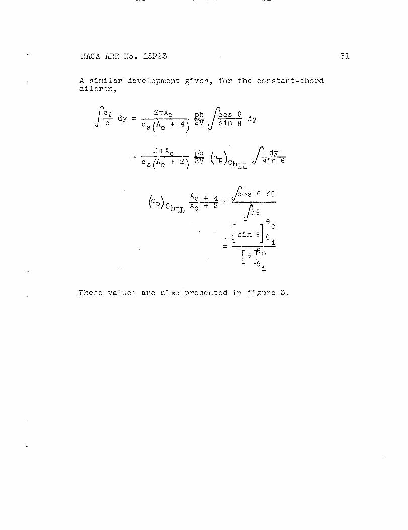
A similar development giveR, for the constant-chordaileron,
o=(Ac + 2) 2v J __
P ChLL AC + _ = Jd8 :80
i
These values are also presented in figure 3.
32 I_ACAARR No. LSF23
REFERENC ES
i. Jones, Robert T.: Theoretical Correction for theLift of Elliptic Wings. Jour. Aero. $ci., vol 9,no. i, Nov. 1941, pp. 8-10.
2. Swanson, Robert S., and To31, Thomas A.: Estimationof Stick Forces from Wind-Tunnel Aileron Data.
NACA ARR No. 3J29, 1943.
3. Swanson, Robert S., and Gil!is, Clarence L.:Limitations of Lifting-Line Theory for Estimationof Aileron Hinge-I;_oment Characteristics. NACA CBNo, 3L02, 1943.
4. 3wanson, Roberb 8., and Crandall, Stewart M.: AnElectromagnetlc-Analogy Method of Solving Lifting-Surface-Theory Problems. NACA ARR No. L5D23, 1945.
5. Swanson, Robert S., and Toll, Thomas A." Jet-BoundaryCorrections for Reflection-Plane I:iodels inRectangular Wind Tunnels. NACA _LRR No. 3E22, 1943.
6. _[unk, Max M.: Fundamentals of Fluid Dynamics forAircraft Designers. The Ronald Press Co., 1929.
7. Ooldsteln, S., and Young, A. D.: The LinearPerturbation Theory of Compressible Flow withApplications to Wind-Tunnel Interference.68G5, Ae. 2252, F.M. 601, British A.R.C., July 6,1943.
8. Harris, Thomas A.: Reduction of Hinge Moments ofAirplane Control Surfaces by Tabs. NACA Rep.No. 528, 1935.
9. Cohen, Doris: A _ethod for Determining the Camberand Twist of a Surface to Support a GivenDistribution of Lift. NACA TN No. 855, 1942.
NACA ARR NO. LSF23 53
_O_444
w0
r'-nor4 o
t4
_oE0
+1
CO+l
_ 0
o J
o_0 --
o
,.-la ,_e -H,_ ®
0 _ _0O_ It} O_ 0
• ,4!
_0 0 _0_I_ _ :cO __
oolo 6 d o!
0 Owl O_
o ,'_ ,-4 _"0 o q _:|
8 :o ,,;• • •
!
_ o _ . . 0;_;l C_ 0 0
.I.0 0* 0 _ 0 0 *,-I • _- * • _ _'! 0 0 0
I
0 __.1 ._0 _ I0 _ 0,,I
o • o o _
_ I 0
0 e0 0 0|
0 0 m
¢-,,I
0
8'8""0 v,..I o 0
_0 06 q S S ,_®
,-, _ ,0 8_ "o £ o ._0 0 0 0
!
0 0 0 0 •• • e-IoGGo
!
C_ 0
• 0
G _ o o
0
0 @
+II I_I
• 0 • ,_, 0 ,_ 0
• _ __ o _ 6 d _ _, _O_ 00_ 0 _0 _ _
• 0 • 0 0 0 " 0 _, cl
! 0 0 0 0 0 ,_I _ ,,4
0
_o0
•I_ ,-4
e_0 _ 0,1
• 0 • 0 0 • 0
_3 0 0 0 0!
GO _ Ow_ 8
• ,, 0 0 0 _ 0" _ 6 o 6 o0 0
e el _o
_J
E_
_o
!0
NACA ARR No. L5F23 Fig. la
E
aS
bom
•_ aS
,-_ .,_
E_o
_o o
• N
-_ o• E_m _
l:_a)
o t_
_1 -_-,_
E_o Cul._ °,-f
,--4
-,-t
,--.I
_ o
-,-"t
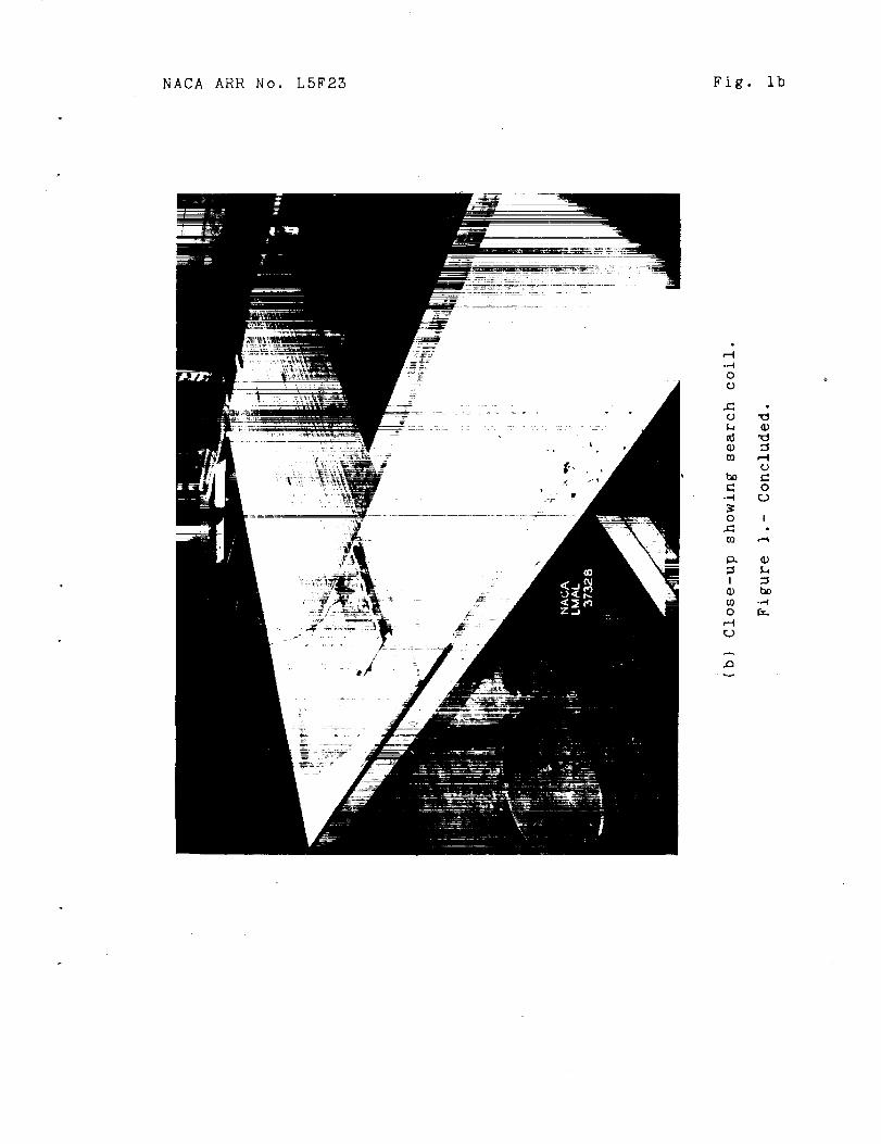
NACA ARR No. LSF25 Fig. ib
o
.o
o
o.-4
o I_z_to r-_
at_O
_0 "_

NACA ARR No. L5F23 Fig. 2
4
do /iI
/
/
Ai
_/ I I --=
_0 80 I00
--tlNATIONAL ADVISORY
COMMITTEE FOR AERONAUTICS
12_ I_ I_0
Figure 2.- Variati_on of damping coefficient with aspect ratio
and taper ratio in terms of slope of section lift curve for
incompressible flow (per degree_. (Lifting-line-theory
values of reference 2 with an effective edge-velocitycorrection applied. )

Fig. 5 NACA ARR No. L5F25
Con._tQnP- c_ord _2/ero,_s.I ,X I ! I
.SO_EIt,,pf'lce,/
_ __ .._._" •-- ---E/hf_/ca/
o;/sro_s.
0 o
NATIONAL ADVISOI_YCOMMITTEE FOIl AERONAUTICS
._ ._ .i ' .,_ ,.oRe/ot'/_'e /o_,,_o_, or" ,,_,_o_,r,_' Q,,/,,_ f_, -_
A c + 4
Figure 5.- Values of (_P)OhLL A c + 2 for various aileron
tip locations. The corrections of figure 4 must beused with these values.
NACA ARR No. LSF23 Fig. 4
\
i
\\
\\
\
\\
E4=g=V
U
Z _ m
o__
.+"4
O"
.."4
_I_
0
0
!
kl
rio.,-4r_
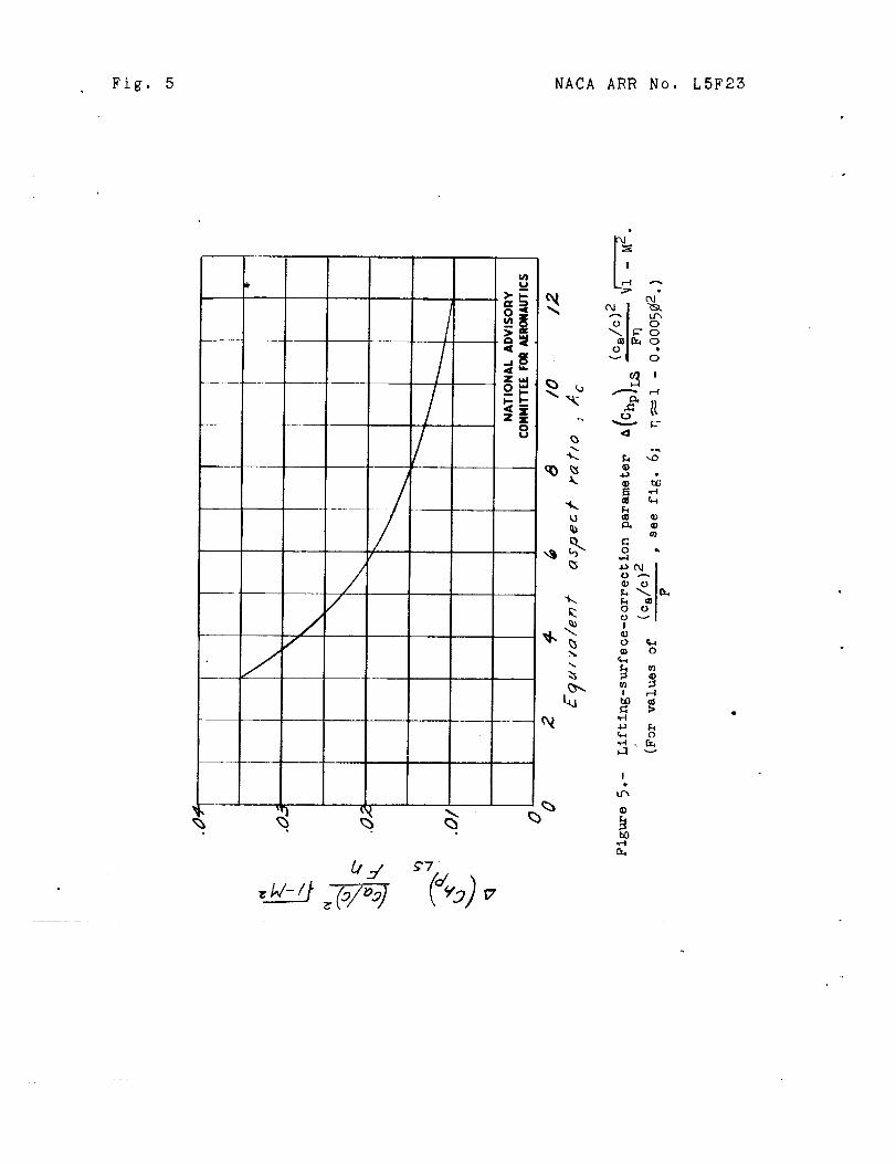
Fig. 5 NACA ARR No. L5FZS
//
/
////
_, j _'7
u)
o
=_
=o_
8
".k.
,,$
k
t_
17
¢X)
O
0
0.,
o_
II _-4
¢I G)
0
!
_ 0
! r-t
_ 0
!
t_,,,.-t
NACA ARR No. L5F23 Fig. 6
/,÷
/// "/_/_; /
1o ////,
.. 2I// ,/ / /
_ //, /#
.... //
_,.,1_1/ / ..... /_, r/i, /
/
/7.ll/ ......
A9"/
/
//
///
/
//
zy /_ --/// / _''--/
/ //
/
, // .1,/_ ////
ro o ,/ .2. ,s ,4- .s .(_
A/leron-chord r_t/o_ ca/c
W/f_ _I/_ron-chord ratio and e_te,_?or/-over/la_q (c_/c)
.oerod_nom/¢ bala_c_-chord ratio. For ig_errla] oerod_l_om/¢aola_ce> _se an effectlle Cae " O.g cz &eference 5).
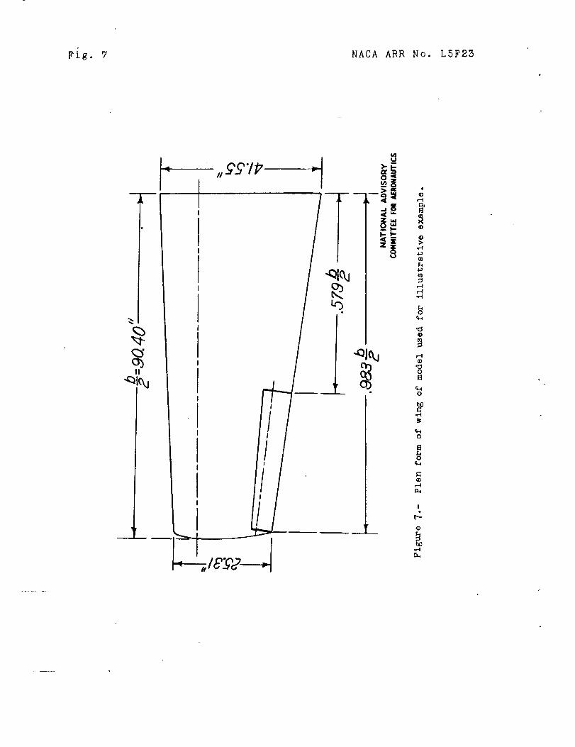
Fig. 7 NACA ARR No. L5F25
_3O]II
I
._LCTP -I
Zou
05
g&
¢6
g)
,,-4
¢D
¢-4,,-.I
o
r.4
o
o
o
%o
r-t
!e
t_
NACA ARR No. L5F2S Fig. 8
/6i.
./2 ¢r-
.08 :
_.04 __
_O_rI
-.08
_-./6
_ZO
_Z4
-2S
\.
_J-c_9
NATIONAL ADVISORYCONHITTEE F011 AEIIOIIAUTICS
I
=03 @`
-15" -I0 -5" 0 6" I0 1,5 20 25
Ai/eron def/ec/lon, _c_, de qFigure _.-"Aileron h/n_e- c_nd rollinq-momenf charc_c/er/s//cs
of /he 040-acole mode/ of/he oirplqne u_ed for /he
/lluJ/r_/ive exomlol_. C_r_cAeri_t/cG p/o/ted ogo/n_f_ileron def/ecfion.
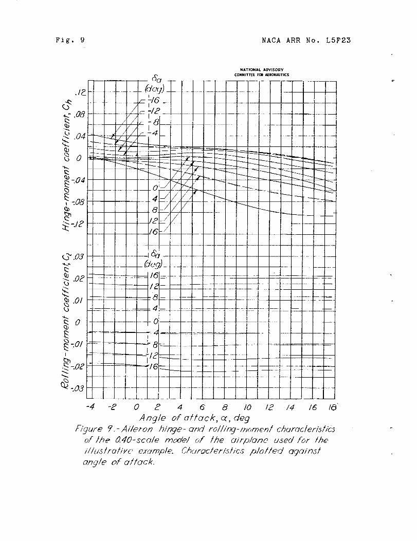
Fig. 9 NACA ARR No. L5F23
NATIONAL ADVISORY
(_(_f CONFIITTEE FOR AERONAUTICS
........... ¢de_)...............
............. =-LI6 __ __t
_/_ ,,--12 ...............I / -,LLal
NACA ARR No. LSF23 Fig. I0
08
_ .................. L....
/
_ .0,2
0
/ ADV,SOnV--
c ......... I, I0 .01 .02 .03 .04 .05 .0_ .07 .OB .0 _) ./0 • II
Helix onjole , pb/2V, tad/on
_-/3DrelO .-Pre/tmllvar_ curve3 u_ed in /he COmlOUiaYlOnof it?e _/_y-t/p Aebx ongle5 and l_e 8f/c/< /or_esJot J/Te Illua_rot/k'e exumple.
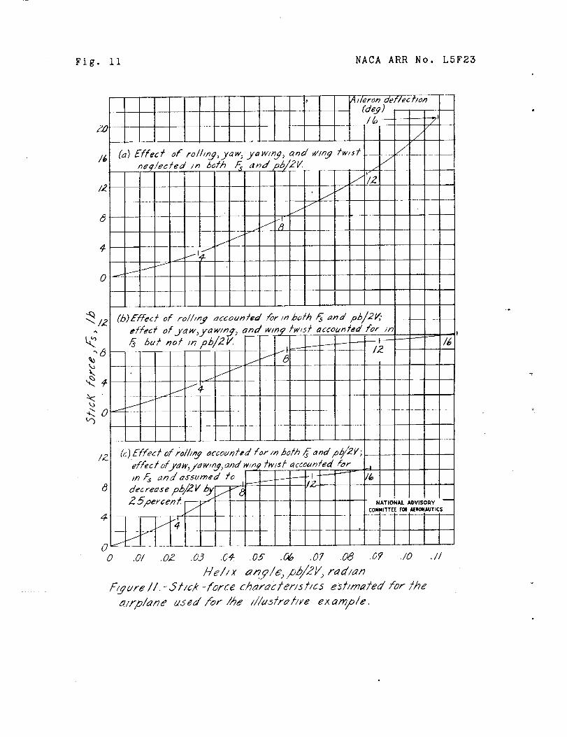
Fig. ii NACA ARR No. L5F23
ZO
I
Effec/ of roll,n3, .yaw,ne]/ected I_ l_oth F_
_o
_.0
....... jjlZ
j/J
L .....
T, I
//
/
wing
(b)Effec/ of roi/in.q accounlede/feelof..s,'_,w,/aw/_j) ond _,m2Fs b,k no: ,_ pb/2V. --
i
/ g//
/
//.t
//
_//eron def/echon
(de9)I:o " -_t
/
//
//w/s/__7
¢
/
/or in ha iT i_s and pb/2Y;/W/st 6lccou/_/md/or in
/Z (a):flee/d iolh_ occounl,d for m both_ a_d p_//2V;efFea/ ofja_v, yawm9 ,and w/f:.:_:s/ a caounled /orm Ps :nd assumed /o _---- _- --i
Z 5percen t.--- _- .....# ..... ;_r../____
/4/
0 .01
-I
-i
NATIO_4AL ADVISORY --
COMMITTEE FOil IERONAUTICS
.02 .03 .0'4 .05 .06 .01 .0_7 .07 .I0
/-/e/i # anyle, pb/2V, red/an
P/Eure II.-3tick -force ch:rac/erlS//as est/mo/ed for/he:lrp/_ne used/or/he ///us/ra//ve exam:/e.
.//
NACA ARR No. L5F23 Figs. 12,15
\\
\\
--- ._
Z_
--o_."
_i- "_
k
at
o _,.4
o_
g,
I
_. __. __ °
g
D
o 7
o
_ o
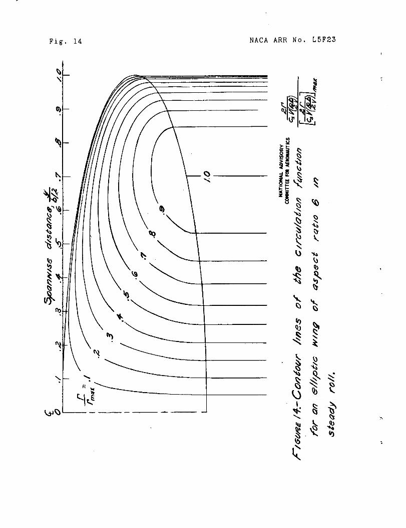
Fig. 14 NACA ARR No. L5F23
%\
.l
%
<
NACA ARR No. L5F23 Fig. 15
/G
wb
.8
/NATIONAL ADVISORY
CO)4NITTE[ FOR AERONAUTICS
.2 .4 .6_ -4, 10
Figure 15.- Induced down,wash function wb/2_ma x for
an elliptical lifting surface of aspect ratio 6 in
steady roll.
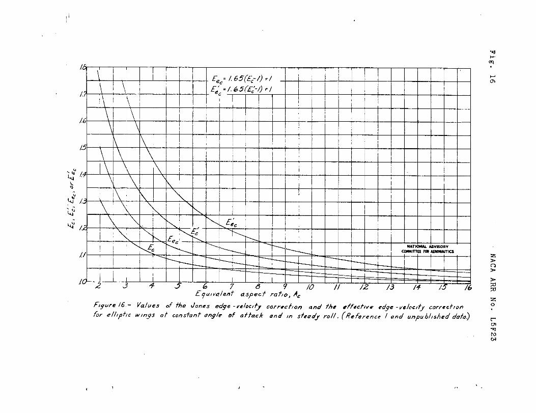
Fig.
16
NACA
ARR
No.
L5F25
i!
....
fl]
:/7....iiiL
I--. o i71/li
y..........
?-
t/
/-./7.....
/I1
it
M/;-i-
I-
1_",3
-'o"_7,,_7'°3
-i.,k
,_2_
"<-,4
iiii
__---
Jtt
..../J
ii
/J
/
____/__
//
/J
/f
/....
7L--=
J/
J
+,.,.:
.i/
-.<
,,,I,,.
@_.
@...klk
_,.._
t_
-_
b_
N_2
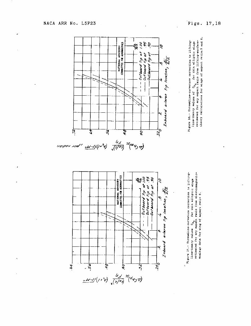
NACA ARR No. L5F23 Figs. 17,18
r
• _
_ o
_o_
o'_'_'._$o
_._
! 1_I_ '
_'xx - _
k
=_ .
o •
, _'_gS_
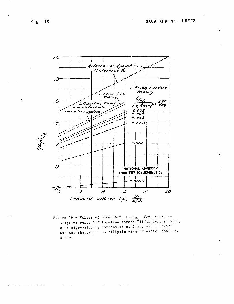
Fig. 19 NACA ARR No. L5F23
, i . .
NATIONAL ADVISORY
COMMITTEE FOE AERONAUTICS
- "_T
--. 0005
o .2. ._ .d .8_r,,,6oa,-d o]leron t_,
,4.O
Figure 19 Values of parameter (a-) C from aileron-"- v h
midpoint rule, lifting-line theory, lifting-line theory
wkth edge-velocity correction applied_ and lifting-
surface theory for an elliptic wing of aspect ratio 6.
M = O,