sipart dr19 manual - siemens · sipart dr19 c73000-b7476-c142-08 1 sipart dr19 6dr 190*--* edition...
TRANSCRIPT
SIPART DR19C73000-B7476-C142-08 1
SIPART DR196DR 190*--*
Edition 08/2010
Manual

2 SIPART DR19C73000-B7476-C142-08
Manual
SIPART DR19C73000-B7476-C142-08
3
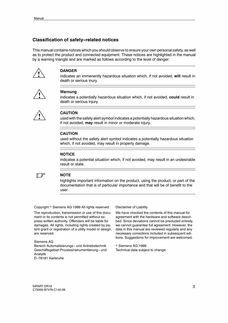
Classification of safety--related notices
Thismanual contains notices which you should observe to ensure your own personal safety, aswellas to protect the product and connected equipment. These notices are highlighted in the manualby a warning triangle and are marked as follows according to the level of danger:
!DANGERindicates an immenently hazardous situation which, if not avoided, will result indeath or serious inury.
!Warnungindicates a potentially hazardous situation which, if not avoided, could result indeath or serious injury.
!CAUTIONusedwith the safety alert symbol indicates a potentially hazardous situationwhich,if not avoided, may result in minor or moderate injury.
CAUTIONused without the safety alert symbol indicates a potentially hazardous situationwhich, if not avoided, may result in property damage.
NOTICEindicates a potential situation which, if not avoided, may result in an undesirableresult or state.
. NOTEhighlights important information on the product, using the product, or part of thedocumentation that is of particular importance and that will be of benefit to theuser.
Copyright e Siemens AG 1999 All rights reserved
The reproduction, transmission or use of this docu-ment or its contents is not permitted without ex-press written authority. Offenders will be liable fordamages. All rights, including rights created by pa-tent grant or registration of a utility model or design,are reserved.
Siemens AGBereich Automatisierungs-- und AntriebstechnikGeschäftsgebiet Prozessinstrumentierung-- undAnalytikD--76181 Karlsruhe
Disclaimer of Liability
We have checked the contents of this manual foragreement with the hardware and software descri-bed. Since deviations cannot be precluded entirely,we cannot guarantee full agreement. However, thedata in this manual are reviewed regularly and anynecessary corrections included in subsequent edi-tions. Suggestions for improvement are welcomed.
e Siemens AG 1999Technical data subject to change.

4 SIPART DR19C73000-B7476-C142-08
Trademarks
SIMATICR, SIPARTR, SIRECR, SITRANSR registered trademarks of Siemens AG.
Third parties using for their own purposes any other names in this document which refer to trade-marks might infringe upon the rights of the trademark owners.
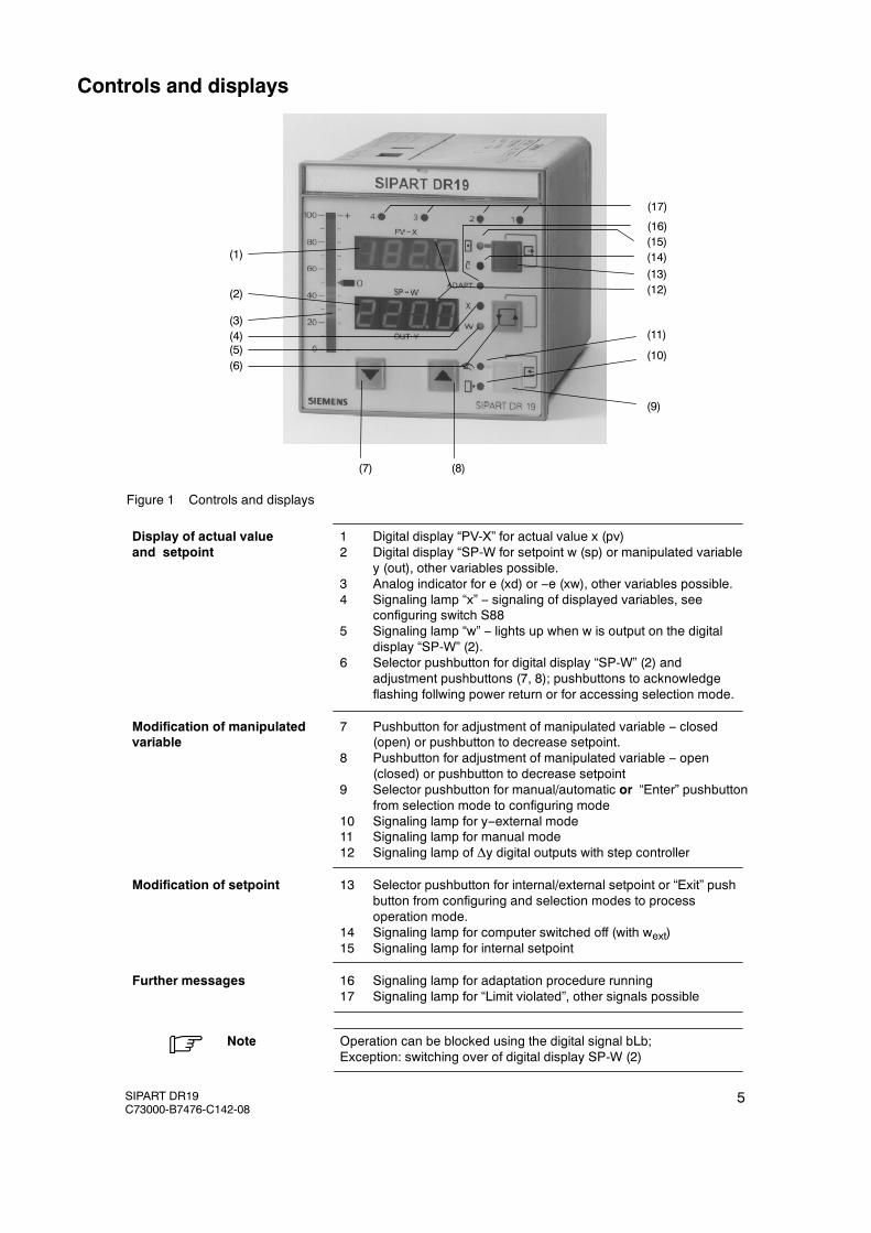
Figure 1 Controls and displays
Display of actual value 1 Digital display “PV-X” for actual value x (pv)and setpoint 2 Digital display “SP-W for setpoint w (sp) or manipulated variable
y (out), other variables possible.3 Analog indicator for e (xd) or --e (xw), other variables possible.4 Signaling lamp “x” -- signaling of displayed variables, see
configuring switch S885 Signaling lamp “w” -- lights up when w is output on the digital
display “SP-W” (2).6 Selector pushbutton for digital display “SP-W” (2) and
adjustment pushbuttons (7, 8); pushbuttons to acknowledgeflashing follwing power return or for accessing selection mode.
Modification of manipulated 7 Pushbutton for adjustment of manipulated variable -- closedvariable (open) or pushbutton to decrease setpoint.
8 Pushbutton for adjustment of manipulated variable -- open(closed) or pushbutton to decrease setpoint
9 Selector pushbutton for manual/automatic or “Enter” pushbuttonfrom selection mode to configuring mode
10 Signaling lamp for y--external mode11 Signaling lamp for manual mode12 Signaling lamp of Δy digital outputs with step controller
Modification of setpoint 13 Selector pushbutton for internal/external setpoint or “Exit” pushbutton from configuring and selection modes to processoperation mode.
14 Signaling lamp for computer switched off (with wext)15 Signaling lamp for internal setpoint
Further messages 16 Signaling lamp for adaptation procedure running17 Signaling lamp for “Limit violated”, other signals possible
Note Operation can be blocked using the digital signal bLb;Exception: switching over of digital display SP-W (2)
.
(1)
(2)
(3)
(5)(4)
(6)
(7) (8)
(10)
(11)
(9)
(12)
(16)
(13)(14)(15)
(17)
Controls and displays
SIPART DR19C73000-B7476-C142-08
5
10
AI3A
S13
AI2A
≤900Ω
S12
AI1A
S8
4 3 2 1
6DR2805-8A
TCinternal
Pt100
3L
+ --
i m
RL2
RL4 RL1
20mA4L
4 3 2 1
200
50
UH
I
+ --
Plug-injumper
open!
6DR2805-8J
≥13
V
≤4.5V
or
AI2
Slot2 S9
Slot1I,U
,R
I,U,R
AI3
Options
UNI
S10
toS11
0%
YN
S18
5 6 12 11
DI1
DI2
24V 5V
9L+ GND
GND
LN
M
+24V
+5V
UREF
S14
S21
24V
5V
I
U
I
S57
15 14 13 8 7
S22
Z S20
YR
S19
wIO/x3 S17x2 S16
x1 S15
4DO24V
2DI
2DOrel.
5DI
Slot3
S92
toS99
4/2
4/7
4/8
4/3
Slot4
SES
5V
MN L
DO2
DO1
+Δy
--Δy AO/ly
0/4to20
mA or
≥19
V≤
50mA
IOptions
Standard-
settings
S1toS3
Analoginputs
S4toS21
Assignm
ent
Slot3
S22
Digitalinputs
S23
toS41
Setpoint
command
S42
toS46
Controlalgorithm
S47
toS49
Ysw
itching
S50
toS54
Ydisplay S55
toS56
AnalogoutputS57
Switching
outputs
S58
Digitaloutputs
S59
toS82
Limitvaluealarms
S83
toS87
Process
display
S88
toS89
Restart
conditions
S90
toS91
Serialinterface
S92
toS99
S4toS7
+ --
S3
=
S-output
6DR1900/1/2
K-output
6DR1900/4/5
1/4
1/3
1/2
1/1
N PE
L2/4
2/3
2/2
2/1
3/6
3/5
3/4
3/3
3/2
3/1
S58
4 3 2 1
DO7
DO8
ttt
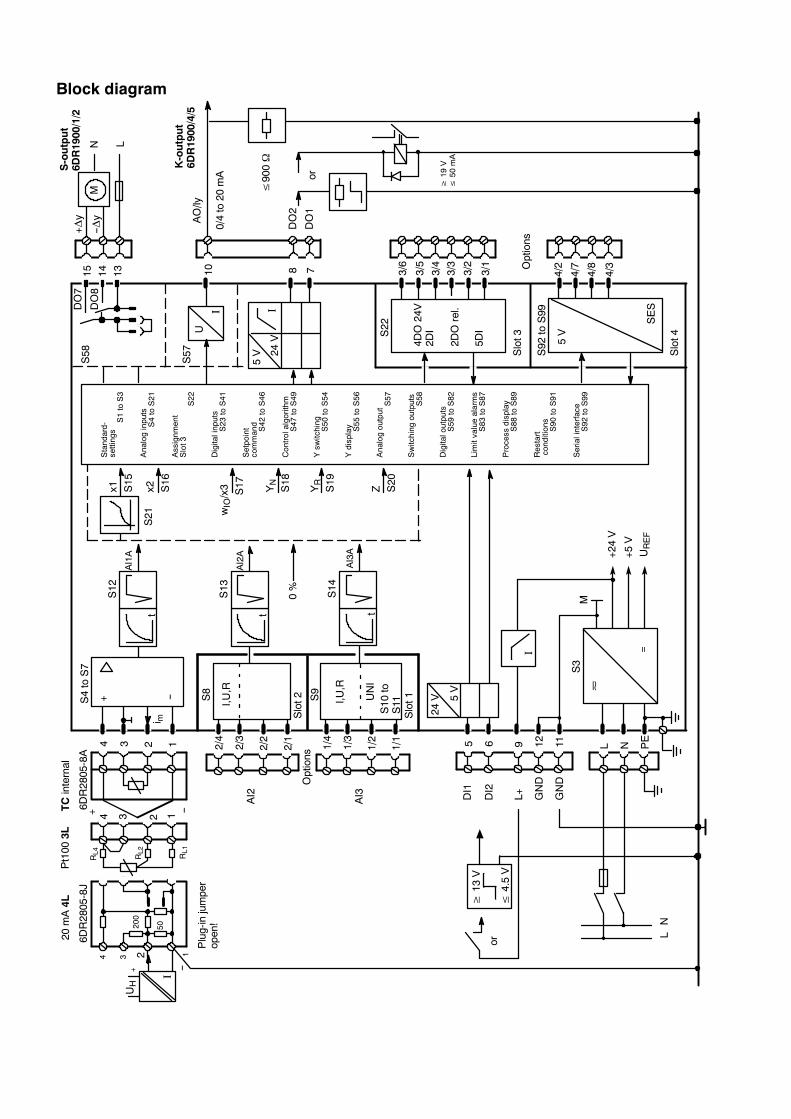
Block diagram
Manual Contents
SIPART DR19C73000-B7476-C142-08
7
ContentsPage
1 General Part -- Fundamental control technology terms 11. . . . . . . . . . . . . . . . . . . .
2 Technical Description 19. . . . . . . . . . . . . . . . . . . . . . . . . . . . . . . . . . . . . . . . . . . . . . . . . . .2.1 Safety notes and scope of delivery 19. . . . . . . . . . . . . . . . . . . . . . . . . . . . . . . . . . . . . . . . . . . . . . . . . .2.2 Application Range 20. . . . . . . . . . . . . . . . . . . . . . . . . . . . . . . . . . . . . . . . . . . . . . . . . . . . . . . . . . . . . . . .2.3 Features 21. . . . . . . . . . . . . . . . . . . . . . . . . . . . . . . . . . . . . . . . . . . . . . . . . . . . . . . . . . . . . . . . . . . . . . . .2.4 Design 25. . . . . . . . . . . . . . . . . . . . . . . . . . . . . . . . . . . . . . . . . . . . . . . . . . . . . . . . . . . . . . . . . . . . . . . . . .2.5 Mode of Operation 28. . . . . . . . . . . . . . . . . . . . . . . . . . . . . . . . . . . . . . . . . . . . . . . . . . . . . . . . . . . . . . . .
2.5.1 Standard controller 28. . . . . . . . . . . . . . . . . . . . . . . . . . . . . . . . . . . . . . . . . . . . . . . . . . . . . . . . . . . . . . . . .2.5.2 Options modules 31. . . . . . . . . . . . . . . . . . . . . . . . . . . . . . . . . . . . . . . . . . . . . . . . . . . . . . . . . . . . . . . . . .
2.6 Technical Data 37. . . . . . . . . . . . . . . . . . . . . . . . . . . . . . . . . . . . . . . . . . . . . . . . . . . . . . . . . . . . . . . . . . .2.6.1 General data 37. . . . . . . . . . . . . . . . . . . . . . . . . . . . . . . . . . . . . . . . . . . . . . . . . . . . . . . . . . . . . . . . . . . . . .2.6.2 Standard controller 39. . . . . . . . . . . . . . . . . . . . . . . . . . . . . . . . . . . . . . . . . . . . . . . . . . . . . . . . . . . . . . . . .2.6.3 Options modules 44. . . . . . . . . . . . . . . . . . . . . . . . . . . . . . . . . . . . . . . . . . . . . . . . . . . . . . . . . . . . . . . . . .
3 Functional description of the structure switches 51. . . . . . . . . . . . . . . . . . . . . . . . . .3.1 General 51. . . . . . . . . . . . . . . . . . . . . . . . . . . . . . . . . . . . . . . . . . . . . . . . . . . . . . . . . . . . . . . . . . . . . . . . .3.2 Analog input signal processing (S3 to S21) 51. . . . . . . . . . . . . . . . . . . . . . . . . . . . . . . . . . . . . . . . . . .3.3 Digital input signal processing (S23 to S42) 54. . . . . . . . . . . . . . . . . . . . . . . . . . . . . . . . . . . . . . . . . .3.4 Controller type (S1, S43 to S46) 59. . . . . . . . . . . . . . . . . . . . . . . . . . . . . . . . . . . . . . . . . . . . . . . . . . . .
3.4.1 General, recurrent functions 59. . . . . . . . . . . . . . . . . . . . . . . . . . . . . . . . . . . . . . . . . . . . . . . . . . . . . . . . .3.4.2 Fixede value controller with 2 independent setpoints (S1 = 0) 64. . . . . . . . . . . . . . . . . . . . . . . . . . . . .3.4.3 Fixed value controller with 5 independent internal setpoints (S1 = 1) 67. . . . . . . . . . . . . . . . . . . . . . .3.4.4 Sequence controller, synchronized controller, SPC-controller 71. . . . . . . . . . . . . . . . . . . . . . . . . . . . .3.4.5 Controlled ratio controller (S1 = 3) 76. . . . . . . . . . . . . . . . . . . . . . . . . . . . . . . . . . . . . . . . . . . . . . . . . . . .3.4.6 Control unit/process display (S1 = 4) 82. . . . . . . . . . . . . . . . . . . . . . . . . . . . . . . . . . . . . . . . . . . . . . . . . .3.4.7 Program controller, program transmitter 89. . . . . . . . . . . . . . . . . . . . . . . . . . . . . . . . . . . . . . . . . . . . . . .3.4.8 Fixed setpoint controller with one setpoint (control system coupling) (S1 = 6) 2) 96. . . . . . . . . . . . . .3.4.9 Sequence controller without Int/Ext-switching (control system coupling) (S1 = 7) 2) 97. . . . . . . . . . .
3.5 Control algorithm 98. . . . . . . . . . . . . . . . . . . . . . . . . . . . . . . . . . . . . . . . . . . . . . . . . . . . . . . . . . . . . . . . .3.6 Controller output structures (S2, S50 to S56) 101. . . . . . . . . . . . . . . . . . . . . . . . . . . . . . . . . . . . . . . . .3.7 Analog output signal processing (S57) 117. . . . . . . . . . . . . . . . . . . . . . . . . . . . . . . . . . . . . . . . . . . . . . .3.8 Digital output signal processing (S58 to S82) 118. . . . . . . . . . . . . . . . . . . . . . . . . . . . . . . . . . . . . . . . .3.9 Adaptation (S49) 120. . . . . . . . . . . . . . . . . . . . . . . . . . . . . . . . . . . . . . . . . . . . . . . . . . . . . . . . . . . . . . . . .3.10 Other functions of the standard controller 123. . . . . . . . . . . . . . . . . . . . . . . . . . . . . . . . . . . . . . . . . . . .
3.10.1 Adaptive filter 123. . . . . . . . . . . . . . . . . . . . . . . . . . . . . . . . . . . . . . . . . . . . . . . . . . . . . . . . . . . . . . . . . . . . .3.10.2 Response threshold AH 124. . . . . . . . . . . . . . . . . . . . . . . . . . . . . . . . . . . . . . . . . . . . . . . . . . . . . . . . . . . .3.10.3 Limit value alarms (S83 to S87) 125. . . . . . . . . . . . . . . . . . . . . . . . . . . . . . . . . . . . . . . . . . . . . . . . . . . . . .3.10.4 Linearizer (S21, oFPA) 126. . . . . . . . . . . . . . . . . . . . . . . . . . . . . . . . . . . . . . . . . . . . . . . . . . . . . . . . . . . . .3.10.5 Restart conditions (S90, S91) 128. . . . . . . . . . . . . . . . . . . . . . . . . . . . . . . . . . . . . . . . . . . . . . . . . . . . . . . .3.10.6 Serial interface and PROFIBUS-DP (S92 to S99) 128. . . . . . . . . . . . . . . . . . . . . . . . . . . . . . . . . . . . . . .
4 Assembly 129. . . . . . . . . . . . . . . . . . . . . . . . . . . . . . . . . . . . . . . . . . . . . . . . . . . . . . . . . . . . . .4.1 Mechanical Installation 129. . . . . . . . . . . . . . . . . . . . . . . . . . . . . . . . . . . . . . . . . . . . . . . . . . . . . . . . . . . .
4.1.1 Work prior to installation 129. . . . . . . . . . . . . . . . . . . . . . . . . . . . . . . . . . . . . . . . . . . . . . . . . . . . . . . . . . . .4.1.2 Installing the controller 132. . . . . . . . . . . . . . . . . . . . . . . . . . . . . . . . . . . . . . . . . . . . . . . . . . . . . . . . . . . . . .4.1.3 Installation of the options modules 133. . . . . . . . . . . . . . . . . . . . . . . . . . . . . . . . . . . . . . . . . . . . . . . . . . . .
4.2 Electrical Connection 134. . . . . . . . . . . . . . . . . . . . . . . . . . . . . . . . . . . . . . . . . . . . . . . . . . . . . . . . . . . . .4.2.1 Warnings and block diagram 134. . . . . . . . . . . . . . . . . . . . . . . . . . . . . . . . . . . . . . . . . . . . . . . . . . . . . . . . .4.2.2 Connection standard controller 138. . . . . . . . . . . . . . . . . . . . . . . . . . . . . . . . . . . . . . . . . . . . . . . . . . . . . . .4.2.3 Connection of the options modules 143. . . . . . . . . . . . . . . . . . . . . . . . . . . . . . . . . . . . . . . . . . . . . . . . . . .4.2.3.1 Modules for analog measuring inputs 143. . . . . . . . . . . . . . . . . . . . . . . . . . . . . . . . . . . . . . . . . . . . . . . . .4.2.3.2 Connection examples for analog measuring inputs with the module 6DR2800-8J 147. . . . . . . . . . . . .4.2.3.3 Modules for expanding the digital inputs and digital outputs 152. . . . . . . . . . . . . . . . . . . . . . . . . . . . . . .
ManualContents
8 SIPART DR19C73000-B7476-C142-08
4.2.4 Connection of the interface module 6DR2803-8C 154. . . . . . . . . . . . . . . . . . . . . . . . . . . . . . . . . . . . . . .4.2.4.1 RS 232 point-to-point 154. . . . . . . . . . . . . . . . . . . . . . . . . . . . . . . . . . . . . . . . . . . . . . . . . . . . . . . . . . . . . . .4.2.4.2 RS 485 bus 155. . . . . . . . . . . . . . . . . . . . . . . . . . . . . . . . . . . . . . . . . . . . . . . . . . . . . . . . . . . . . . . . . . . . . . .4.2.4.3 PROFIBUS-DP, 6DR2803-8P 156. . . . . . . . . . . . . . . . . . . . . . . . . . . . . . . . . . . . . . . . . . . . . . . . . . . . . . . .
5 Operation 159. . . . . . . . . . . . . . . . . . . . . . . . . . . . . . . . . . . . . . . . . . . . . . . . . . . . . . . . . . . . . .5.1 General 159. . . . . . . . . . . . . . . . . . . . . . . . . . . . . . . . . . . . . . . . . . . . . . . . . . . . . . . . . . . . . . . . . . . . . . . . .5.2 Process operation mode 160. . . . . . . . . . . . . . . . . . . . . . . . . . . . . . . . . . . . . . . . . . . . . . . . . . . . . . . . . .
5.2.1 General 160. . . . . . . . . . . . . . . . . . . . . . . . . . . . . . . . . . . . . . . . . . . . . . . . . . . . . . . . . . . . . . . . . . . . . . . . . .5.2.2 Operation and displays in the program controller setting (S1 = 5) 161. . . . . . . . . . . . . . . . . . . . . . . . . .
5.3 Selection mode 164. . . . . . . . . . . . . . . . . . . . . . . . . . . . . . . . . . . . . . . . . . . . . . . . . . . . . . . . . . . . . . . . . .5.4 Configuration modes 166. . . . . . . . . . . . . . . . . . . . . . . . . . . . . . . . . . . . . . . . . . . . . . . . . . . . . . . . . . . . . .
5.4.1 General, Online and Offline modes 166. . . . . . . . . . . . . . . . . . . . . . . . . . . . . . . . . . . . . . . . . . . . . . . . . . .5.4.2 Configuration mode online-parameters onPA 167. . . . . . . . . . . . . . . . . . . . . . . . . . . . . . . . . . . . . . . . . . .5.4.3 Configuration mode adaptation AdAP 169. . . . . . . . . . . . . . . . . . . . . . . . . . . . . . . . . . . . . . . . . . . . . . . .5.4.4 Configuration level offline parameters oFPA 173. . . . . . . . . . . . . . . . . . . . . . . . . . . . . . . . . . . . . . . . . . .5.4.5 Configuration level program controller CLPA 176. . . . . . . . . . . . . . . . . . . . . . . . . . . . . . . . . . . . . . . . . . .5.4.6 Configuration mode structure switch StrS 180. . . . . . . . . . . . . . . . . . . . . . . . . . . . . . . . . . . . . . . . . . . . . .5.4.7 Set analog input AI1 CAE1 191. . . . . . . . . . . . . . . . . . . . . . . . . . . . . . . . . . . . . . . . . . . . . . . . . . . . . . . . . .5.4.7.1 Measuring range for mV (S5 = 0) 193. . . . . . . . . . . . . . . . . . . . . . . . . . . . . . . . . . . . . . . . . . . . . . . . . . . . .5.4.7.2 Measuring range for U, I (S5 = 0) 193. . . . . . . . . . . . . . . . . . . . . . . . . . . . . . . . . . . . . . . . . . . . . . . . . . . . .5.4.7.3 Measuring range for thermocouple with internal reference point (S5 = 1) 193. . . . . . . . . . . . . . . . . . . .5.4.7.4 Measuring range for thermocouple with internal reference point (S5 = 2) 194. . . . . . . . . . . . . . . . . . . .5.4.7.5 Measuring range for PT100 four-wire and three-wire connection (S5 = 3, 4) 194. . . . . . . . . . . . . . . . .5.4.7.6 Measuring range for PT100 two-wire connection (S5 = 5) 195. . . . . . . . . . . . . . . . . . . . . . . . . . . . . . . . .5.4.7.7 Measuring range for resistance potentiometer (S5 = 6, 7) 195. . . . . . . . . . . . . . . . . . . . . . . . . . . . . . . . .5.4.8 Set UNI-module CAE3 196. . . . . . . . . . . . . . . . . . . . . . . . . . . . . . . . . . . . . . . . . . . . . . . . . . . . . . . . . . . . . .5.4.8.1 Measuring range for mV (S10 = 0) 197. . . . . . . . . . . . . . . . . . . . . . . . . . . . . . . . . . . . . . . . . . . . . . . . . . . .5.4.8.2 Measuring range for U, I (S10 = 0) 197. . . . . . . . . . . . . . . . . . . . . . . . . . . . . . . . . . . . . . . . . . . . . . . . . . . .5.4.8.3 Measuring range for thermocouple with internal reference point (S10 = 1) 198. . . . . . . . . . . . . . . . . . .5.4.8.4 Measuring range for thermocouple with internal reference point (S10 = 2) 198. . . . . . . . . . . . . . . . . . .5.4.8.5 Measuring range for PT100 four-wire and three-wire connection (S10 = 3, 4) 199. . . . . . . . . . . . . . . .5.4.8.6 Measuring range for PT100 two-wire connection (S10 = 5) 199. . . . . . . . . . . . . . . . . . . . . . . . . . . . . . .5.4.8.7 Measuring range for resistance potentiometer (S10 = 6, 7) 200. . . . . . . . . . . . . . . . . . . . . . . . . . . . . . . .5.4.9 APSt (All Preset) Reset to factory setting 201. . . . . . . . . . . . . . . . . . . . . . . . . . . . . . . . . . . . . . . . . . . . . .
5.5 CPU self-diagnostics 202. . . . . . . . . . . . . . . . . . . . . . . . . . . . . . . . . . . . . . . . . . . . . . . . . . . . . . . . . . . . . .
6 Commissioning 203. . . . . . . . . . . . . . . . . . . . . . . . . . . . . . . . . . . . . . . . . . . . . . . . . . . . . . . .6.1 Adapting the controller direction of effect to the controlled system 203. . . . . . . . . . . . . . . . . . . . . . . .6.2 Setting of actuating time in K-controllers (S2 = 0) 205. . . . . . . . . . . . . . . . . . . . . . . . . . . . . . . . . . . . . .6.3 Adaptation of the S-controller to the actuating drive 205. . . . . . . . . . . . . . . . . . . . . . . . . . . . . . . . . . . .6.4 Setting the filter and the response threshold 207. . . . . . . . . . . . . . . . . . . . . . . . . . . . . . . . . . . . . . . . . .6.5 Automatic setting of control parameters by the adaptation method 208. . . . . . . . . . . . . . . . . . . . . . .6.6 Manual setting of the control parameters without knowledge of the plant behavior 208. . . . . . . . . .6.7 Manual setting of the control parameters according to the transition function 210. . . . . . . . . . . . . .
7 Application examples for configuring the controller 211. . . . . . . . . . . . . . . . . . . . . . .7.1 General 211. . . . . . . . . . . . . . . . . . . . . . . . . . . . . . . . . . . . . . . . . . . . . . . . . . . . . . . . . . . . . . . . . . . . . . . . .7.2 Working with different setpoints 213. . . . . . . . . . . . . . . . . . . . . . . . . . . . . . . . . . . . . . . . . . . . . . . . . . . . .7.3 Program controller, program transmitter 217. . . . . . . . . . . . . . . . . . . . . . . . . . . . . . . . . . . . . . . . . . . . . .7.4 Configuration examples 226. . . . . . . . . . . . . . . . . . . . . . . . . . . . . . . . . . . . . . . . . . . . . . . . . . . . . . . . . . .7.5 Configuring tool, forms 234. . . . . . . . . . . . . . . . . . . . . . . . . . . . . . . . . . . . . . . . . . . . . . . . . . . . . . . . . . . .
Manual Contents
SIPART DR19C73000-B7476-C142-08
9
8 Maintenance 241. . . . . . . . . . . . . . . . . . . . . . . . . . . . . . . . . . . . . . . . . . . . . . . . . . . . . . . . . . .8.1 General information and handling 241. . . . . . . . . . . . . . . . . . . . . . . . . . . . . . . . . . . . . . . . . . . . . . . . . . .8.2 Exchanging components 242. . . . . . . . . . . . . . . . . . . . . . . . . . . . . . . . . . . . . . . . . . . . . . . . . . . . . . . . . .8.3 LED-test and software state 244. . . . . . . . . . . . . . . . . . . . . . . . . . . . . . . . . . . . . . . . . . . . . . . . . . . . . . . .8.4 Spare parts list 245. . . . . . . . . . . . . . . . . . . . . . . . . . . . . . . . . . . . . . . . . . . . . . . . . . . . . . . . . . . . . . . . . . .8.5 Ordering data 246. . . . . . . . . . . . . . . . . . . . . . . . . . . . . . . . . . . . . . . . . . . . . . . . . . . . . . . . . . . . . . . . . . . .
9 General explanation of abbreviations for SIPART DR 247. . . . . . . . . . . . . . . . . . . . . .
Index 253. . . . . . . . . . . . . . . . . . . . . . . . . . . . . . . . . . . . . . . . . . . . . . . . . . . . . . . . . . . . . . . . . . . . . . . .

ManualContents
10 SIPART DR19C73000-B7476-C142-08
1 General Part -- Fundamental control technology termsManual
SIPART DR19C73000-B7476-C142-08
11
1 General Part -- Fundamental control technology terms
D Control loop
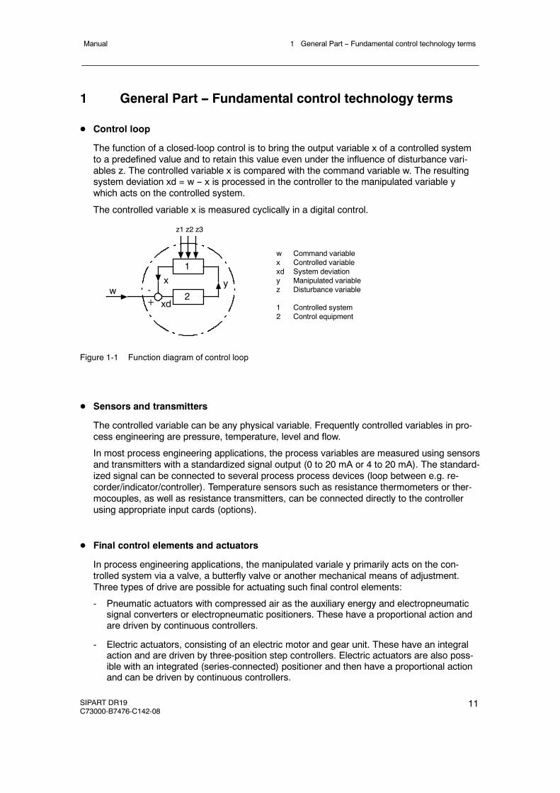
The function of a closed-loop control is to bring the output variable x of a controlled systemto a predefined value and to retain this value even under the influence of disturbance vari-ables z. The controlled variable x is compared with the command variable w. The resultingsystem deviation xd = w -- x is processed in the controller to the manipulated variable ywhich acts on the controlled system.
The controlled variable x is measured cyclically in a digital control.
w Command variablex Controlled variablexd System deviationy Manipulated variablez Disturbance variable
1 Controlled system2 Control equipment
z1 z2 z3
1
2yx
xdw -
+
Figure 1-1 Function diagram of control loop
D Sensors and transmitters
The controlled variable can be any physical variable. Frequently controlled variables in pro-cess engineering are pressure, temperature, level and flow.
In most process engineering applications, the process variables are measured using sensorsand transmitters with a standardized signal output (0 to 20 mA or 4 to 20 mA). The standard-ized signal can be connected to several process process devices (loop between e.g. re-corder/indicator/controller). Temperature sensors such as resistance thermometers or ther-mocouples, as well as resistance transmitters, can be connected directly to the controllerusing appropriate input cards (options).
D Final control elements and actuators
In process engineering applications, the manipulated variale y primarily acts on the con-trolled system via a valve, a butterfly valve or another mechanical means of adjustment.Three types of drive are possible for actuating such final control elements:
- Pneumatic actuators with compressed air as the auxiliary energy and electropneumaticsignal converters or electropneumatic positioners. These have a proportional action andare driven by continuous controllers.
- Electric actuators, consisting of an electric motor and gear unit. These have an integralaction and are driven by three-position step controllers. Electric actuators are also poss-ible with an integrated (series-connected) positioner and then have a proportional actionand can be driven by continuous controllers.
1 General Part -- Fundamental control technology terms Manual
12 SIPART DR19C73000-B7476-C142-08
- Hydraulic actuators with electric oil pump and electrohydraulic positioner. These have aproportional action and are also driven by continuous controllers.These types of actuators can be used to implement continuous controls.
- Temperature control loops with diret electric or gas heating and/or cooling systems aredriven by two-postion controllers (on/off controllers). The two-position controllers with theheating or cooling medium via relays, external contactors or thyristor controllers. The ma-nipulated variable y is the on/off ratio. These are referred to as discontinuous controls.
D Controllers and control response
The controlled variable x is compared with the command variable w in the input circuit of thecontroller, and the system deviation xd is determined. This is processed with or without atime response into the output signal. The output signal of the amplifier can directly representthe manipulated variable y if e.g. proportional-action final control elements are to be drivenby it.
In the case of electric actuators, the manipulated variable is produced by the actuator. Therequired positioning inrements are derived from the controller ouptut as a pulse-width-modu-lated signal by conversion.
Depending on the design of this circuit, the controller has a proportional action (P), a propor-tional-plus-derivative action (PD), a proportional-plus-integral action (PI) or a proportional-plus-integral-plus-derivative action (PID).
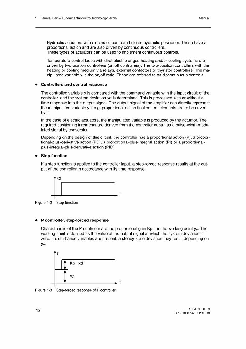
D Step function
If a step function is applied to the controller input, a step-forced response results at the out-put of the controller in accordance with its time response.
xd
t
Figure 1-2 Step function
D P controller, step-forced response
Characteristic of the P controller are the proportional gain Kp and the working point yo. Theworking point is defined as the value of the output signal at which the system deviation iszero. If disturbance variables are present, a steady-state deviation may result depending onyo.
y
t
Kp · xd
yO
Figure 1-3 Step-forced response of P controller
1 General Part -- Fundamental control technology termsManual
SIPART DR19C73000-B7476-C142-08
13
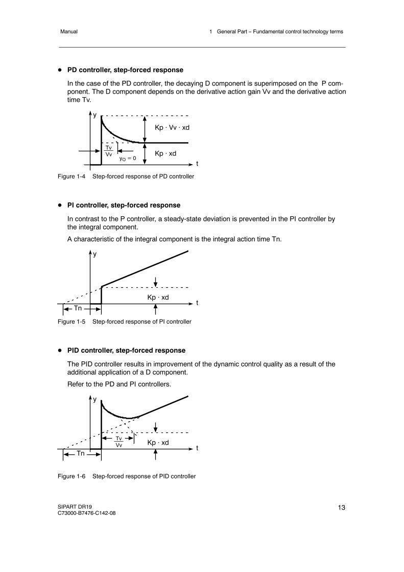
D PD controller, step-forced response
In the case of the PD controller, the decaying D component is superimposed on the P com-ponent. The D component depends on the derivative action gain Vv and the derivative actiontime Tv.
y
t
TvVv
Kp · Vv · xd
Kp · xdyO = 0
Figure 1-4 Step-forced response of PD controller
D PI controller, step-forced response
In contrast to the P controller, a steady-state deviation is prevented in the PI controller bythe integral component.
A characteristic of the integral component is the integral action time Tn.
y
tKp · xd
Tn
Figure 1-5 Step-forced response of PI controller
D PID controller, step-forced response
The PID controller results in improvement of the dynamic control quality as a result of theadditional application of a D component.
Refer to the PD and PI controllers.
y
tKp · xd
Tn
TvVv
Figure 1-6 Step-forced response of PID controller
1 General Part -- Fundamental control technology terms Manual
14 SIPART DR19C73000-B7476-C142-08
D Controller output signal
The controller ouptut signal must be adapted to the final control element. The following mustbe used according to the type of drive/final control element:
Type of drive/actuator Controller output signal
Electric actuators Three-position step controllers
Pneumatic and hydraulic actuators Continuous controllers
Direct heaters/coolers Two-position controllers
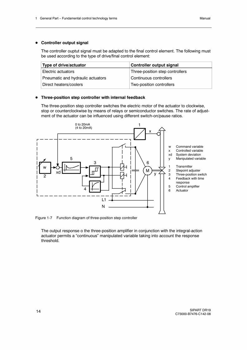
D Three-position step controller with internal feedback
The three-position step controller switches the electric motor of the actuator to clockwise,stop or counterclockwise by means of relays or semiconductor switches. The rate of adjust-ment of the actuator can be influenced using different switch-on/pause ratios.
w Command variablex Controlled variablexd System deviationy Manipulated variable
1 Transmitter2 Stepoint adjuster3 Three-position switch4 Feedback with time
response5 Control amplifier6 Actuator
2M
wxd
53
4
L1
N
1x
6
y
0 to 20mA(4 to 20mA)
Figure 1-7 Function diagram of three-position step controller
The output response o the three-position amplifier in conjunction with the integral-actionactuator permits a “continuous” manipulated variable taking into account the responsethreshold.
1 General Part -- Fundamental control technology termsManual
SIPART DR19C73000-B7476-C142-08
15
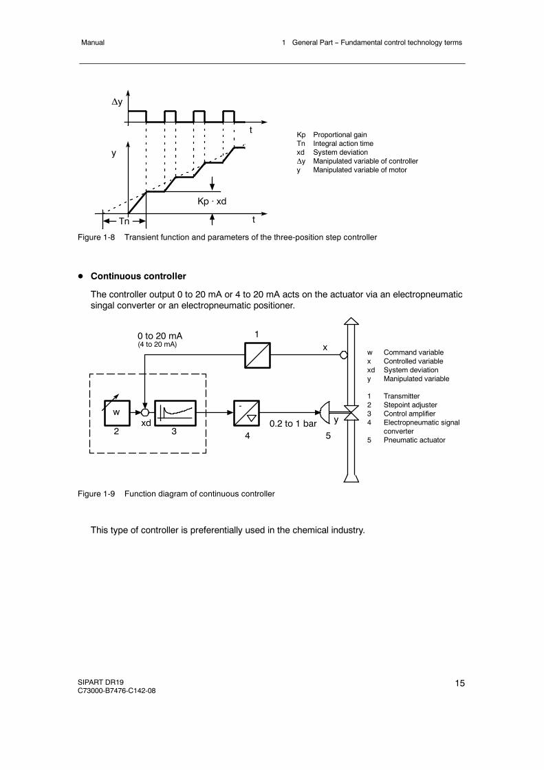
Kp Proportional gainTn Integral action timexd System deviationΔy Manipulated variable of controllery Manipulated variable of motor
Tn
Kp · xd
y
Δy
t
t
Figure 1-8 Transient function and parameters of the three-position step controller
D Continuous controller
The controller output 0 to 20 mA or 4 to 20 mA acts on the actuator via an electropneumaticsingal converter or an electropneumatic positioner.
2
wxd
3
1x
y-
4
0 to 20 mA(4 to 20 mA)
0.2 to 1 bar
w Command variablex Controlled variablexd System deviationy Manipulated variable
1 Transmitter2 Stepoint adjuster3 Control amplifier4 Electropneumatic signal
converter5 Pneumatic actuator5
Figure 1-9 Function diagram of continuous controller
This type of controller is preferentially used in the chemical industry.
1 General Part -- Fundamental control technology terms Manual
16 SIPART DR19C73000-B7476-C142-08
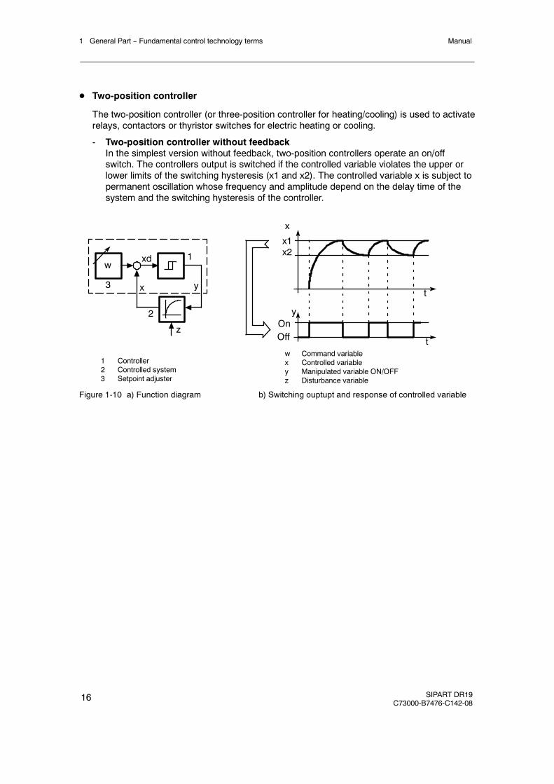
D Two-position controller
The two-position controller (or three-position controller for heating/cooling) is used to activaterelays, contactors or thyristor switches for electric heating or cooling.
- Two-position controller without feedbackIn the simplest version without feedback, two-position controllers operate an on/offswitch. The controllers output is switched if the controlled variable violates the upper orlower limits of the switching hysteresis (x1 and x2). The controlled variable x is subject topermanent oscillation whose frequency and amplitude depend on the delay time of thesystem and the switching hysteresis of the controller.
1 Controller2 Controlled system3 Setpoint adjuster
3
wxd 1
y
2
x
zt
t
x
y
x1x2
w Command variablex Controlled variabley Manipulated variable ON/OFFz Disturbance variable
OnOff
Figure 1-10 a) Function diagram b) Switching ouptupt and response of controlled variable
1 General Part -- Fundamental control technology termsManual
SIPART DR19C73000-B7476-C142-08
17
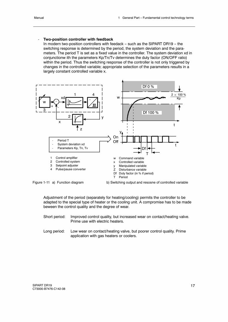
- Two-position controller with feedbackIn modern two-position controllers with feedack -- such as the SIPART DR19 -- theswitching response is determined by the period, the system deviation and the para-meters. The period T is set as a fixed value in the controller. The system deviation xd inconjunctionw ith the parameters Kp/Tn/Tv determines the duty factor (ON/OFF ratio)within the period. Thus the switching response of the controller is not only triggered bychanges in the controlled variable; appropriate selection of the parameters results in alargely constant controlled variable x.
1 Control amplifier2 Controlled system3 Setpoint adjuster4 Pulse/pause converter
3
wxd
1
y2x
z
t
t
yOnOff
-
-+-
4
DfT
w
Df 0 %
Df 100 %
2¢ 100 %Kp
- Period T- System deviation xd- Parameters Kp, Tn, Tv
w Command variablex Controlled variabley Manipulated variableZ Disturbance variableDf Duty factor (in % if period)T Period
Figure 1-11 a) Function diagram b) Switching output and resosne of controlled variable
Adjustment of the period (separately for heating/cooling) permits the controller to beadapted to the special type of heater or the cooling unit. A compromise has to be madebeween the control quality and the degree of wear.
Short period: Improved control quality, but increased wear on contact/heating valve.Prime use with electric heaters.
Long period: Low wear on contact/heating valve, but poorer control quality. Primeapplication with gas heaters or coolers.

1 General Part -- Fundamental control technology terms Manual
18 SIPART DR19C73000-B7476-C142-08
2 Technical Description2.1 Safety notes and scope of delivery
Manual
SIPART DR19C73000-B7476-C142-08
19
2 Technical Description
2.1 Safety notes and scope of delivery
! WARNING
When operating electrical equipment, certain parts of this equipment automati-cally carry dangerous voltages. Failure to observe these instructions could the-refore lead to serious injury ormaterial damage.Only properly trained andqua-lified personnel are allowed to work on this equipment. This personnel must befully conversant with all the warnings and commissioning measures as descri-bed in this user’s guide.The perfect and safe operation of this equipment is conditional upon propertransport, proper storage, installation and assembly as well as on careful ope-ration and commissioning.
D Scope of delivery
When the controller is delivered the box also contains:
1 Controller as ordered1 Three--pin plug at 115/230 V AC or special plug at 24 V UC2 Clamping elements2 Adhesive labels “Power supply 115 V” (for 115/230 V version).1 CD ROM with documentation
D Standard controllers
The following variants of the SIPART DR19 are available for delivery:
Order number Output stage Power supply
6DR1900-4 S/K-output 24 V UC6DR1900-5 S/K-output 115/230 V AC, switchable
D Options modules (signal converters)
Signal converters have separate ordering and delivery items.For handling reasons standard controllers and signal converters which were ordered at thesame time may be delivered by separate mail.
D Documentation
This user’s guide is available in the following languages:German C73000-B7400-C142English C73000-B7476-C142
2 Technical Description2.2 Application Range
Manual
20 SIPART DR19C73000-B7476-C142-08
D Subject to modifications
The user’s guide has been compiled with great care. However, it may be necessary, withinthe scope of product care, to make changes to the product and its operation without priornotice which are not contained in this user’s guide. We are not liable for any costs ensuingfor this reason.
2.2 Application Range
D Application
The SIPART DR19 industrial controller is a digitally operating unit of the mid to upper per-formance class. It is used in industry, for example in the foods and tobacco industry but alsoin automatic control systems in process engineering such as chemicals and petrochemicals,furnace building and ironworks/foundries and in the fine ceramics and glass industry.
The controller’s great flexibility makes it suitable for use in simple or intermeshed control cir-cuits. The wide setting ranges of the controller parameters allow the SIPART DR19 to beused in process engineering for fast (e.g. flow) and slow (e.g. temperature) controlled sys-tems. The controller determines the optimum control parameters independently on requestwithout the user being expected to have any prior knowledge of how the control loop mayrespond.
D Controlling tasks
The input structure of the SIPART DR19 controller can be changed by configuring so thatthe following control problems can be solved.
- Fixed value controls, even with disturbance variables applied at the input- Fixed value controls for control system coupling*)- Three-component controls- Control circuits with up to two internal setpoints- Control circuits with up to five setpoints- Follow-up/synchronization controls- Follow-up controls for control system coupling*)- Disturbance variables applied at the output- Computer-controlled control circuits in SPC operation- Ratio controls with fixed or manipulated variables- Program controllers and program encoder function (6DR1900/2/5)
The SIPART DR19 can also be configured as a control device, a manual control unit or afunction encoder.
The SIPART DR19 controller can be used as a continuous controller with 0/4 to 20 mAoutput, as a step switching controller with built-in relay for controlling motor drives or as atwo-position controller for heating/cooling.
Overlaid control functions or status and alarm messages are possible through digital inputsand outputs.
*) as of software version --A7
2 Technical Description2.3 Features
Manual
SIPART DR19C73000-B7476-C142-08
21
2.3 Features
D General
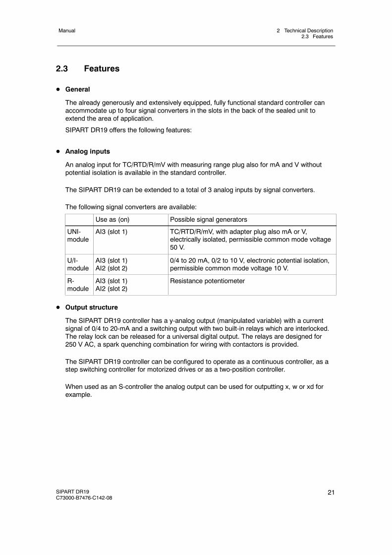
The already generously and extensively equipped, fully functional standard controller canaccommodate up to four signal converters in the slots in the back of the sealed unit toextend the area of application.
SIPART DR19 offers the following features:
D Analog inputs
An analog input for TC/RTD/R/mV with measuring range plug also for mA and V withoutpotential isolation is available in the standard controller.
The SIPART DR19 can be extended to a total of 3 analog inputs by signal converters.
The following signal converters are available:
Use as (on) Possible signal generators
UNI-module
AI3 (slot 1) TC/RTD/R/mV, with adapter plug also mA or V,electrically isolated, permissible common mode voltage50 V.
U/I-module
AI3 (slot 1)AI2 (slot 2)
0/4 to 20 mA, 0/2 to 10 V, electronic potential isolation,permissible common mode voltage 10 V.
R-module
AI3 (slot 1)AI2 (slot 2)
Resistance potentiometer
D Output structure
The SIPART DR19 controller has a y-analog output (manipulated variable) with a currentsignal of 0/4 to 20-mA and a switching output with two built-in relays which are interlocked.The relay lock can be released for a universal digital output. The relays are designed for250 V AC, a spark quenching combination for wiring with contactors is provided.
The SIPART DR19 controller can be configured to operate as a continuous controller, as astep switching controller for motorized drives or as a two-position controller.
When used as an S-controller the analog output can be used for outputting x, w or xd forexample.
2 Technical Description2.3 Features
Manual
22 SIPART DR19C73000-B7476-C142-08
! WARNING
The relays are designed for a maximum switching voltage of 250 V AC/8 A inovervoltage class III anddegreeof contamination 2according toDINEN61010Part 1.The same applies for the air- and creep lines on the circuit board.Resonance increases up to three times the rated operating voltage may occurwhen phase shift motors are controlled. These voltages are available at theopen relay contact. Therefore suchmotorsmay only be controlled under obser-vance of the technical data and the pertinent safety conditions via isolatedswitching elements.
D Voltage output
A voltage output L+ for feeding two-wire transmitters or contacts for digital inputs.
D Slots for options
Four rear slots can be used for functional expansions. The options modules are slot codedso that wrong installation is largely ruled out.Slot assignment, see figure 2-2 Rear view, page 27.
D Power supply unit
The power supply unit is designed for the following voltages depending on the standardcontroller:- 230 V/115 V AC, switchable by plug-in jumpers in the device- 24 V UC
D Digital inputs
Two digital inputs, potential-boundIt can be upgraded to four or seven potential-bound digital inputs with signal converters.The digital inputs can be assigned to the following controller-internal switching signals.
bLb Blocking operationBlocking the entire instrument operation and configuring.Exception: Switching the w/x-digital display
bLS Blocking structuringWith this signal the controller only allows switching to theonline-parameterization levels outside process operation. In this way theparameters for adapting the instrument to the process and the necessarysettings for adaptation can be selected. Structuring is blocked.
bLPS Blocking parameterization and structuringThe entire configuring of the instrument is blocked, this means theparameterization as well. Only the normal process operation according to thepreselected controller type is permitted.
2 Technical Description2.3 Features
Manual
SIPART DR19C73000-B7476-C142-08
23
CB Computer standbyDepending on the controller type, this digital signal together with theinternal/external key causes either switching in the setpoint range.
He Manual externalThis signal blocks the output of the controller and enables direct manualadjustment of the manipulated variable on the front control panel.
N TrackingWith this signal the output of the K controller and the three-position steppercontroller with external position feedback is tracked to the tracking signal yN.
Si Safety operationThe output of the K controller or the three-position stepper controller withexternal position feedback accepts the parameterized safety value. Inthree-position stepper controllers with internal position feedback, themanipulated variable runs defined to 0 or 100 %.
P P-operationSwitching from PI (PID) to P (PD)-controller (i.e. switch off the I-part)This function simplifies automatic start-up of control circuits.
PU Setpoint switching in 5 setpoint operation (S1 = 2) or program switching inprogram function (S1 = 5)
tS Switch off the setpoint ramp timeReset at S1 = 5 (program controller, transmitter = reset the program setpoint)
tSH Stop setpoint change (setpoint ramp)
+yBL / --yBLDirection-dependent blocking of the manipulated variableDirection-dependent limiting of the manipulated variable by external signals,e.g. the controller output can be blocked by the limit switches of an actuatingdrive. This limiting is effective in every operating mode.
D Digital outputs
Two digital outputs, active, potential-bound.It can be upgraded to four or six digital outputs with signal converters.The digital outputs are loadable up to 50 mA per output for direct tripping of relays.The digital outputs can also be used for the variable output, the relay outputs are then freefor any digital signal output.The following controller-internal switching signals can be assigned to the digital outputs.
RB Computer standbyMessage that the controller can be switched to the external setpoint by the CBsignal.
RC Computer operationMessage that the controller is presently in computer operation or that it hasbeen switched over to the external setpoint by the CB signal.
2 Technical Description2.3 Features
Manual
24 SIPART DR19C73000-B7476-C142-08
H Manual modeMessage that the controller has been switched over to manual mode with themanual/automatic key.
Nw Tracking operation activeMessage that the controller is in tracking operation.
A1 to A4 Alarm output Alarm 1 to Alarm 4
MUF Group alarm transmitter faultThe instruments’s analog input signals can be monitored for exceeding of themeasuring range. This signal gives a group alarm if an error is detected.
Δw Output of switching signals for setpoint adjustmentThis function is only active when the controller is structured as a control unit(S1=4).
CLb1 to CLb6 Output of status messages of the program controller (S1 = 5)
Δy Output of incremental y-adjustmentAssignment is only possible to DO1, 2, 7 or 8.
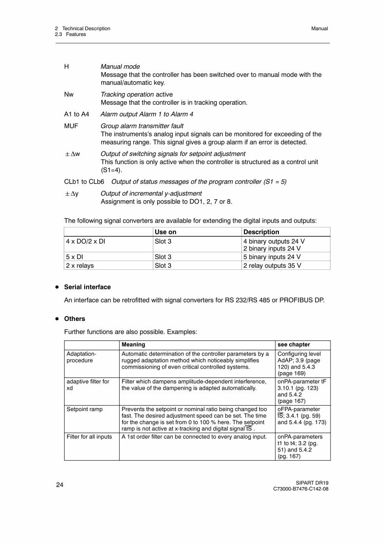
The following signal converters are available for extending the digital inputs and outputs:
Use on Description4 x DO/2 x DI Slot 3 4 binary outputs 24 V
2 binary inputs 24 V5 x DI Slot 3 5 binary inputs 24 V2 x relays Slot 3 2 relay outputs 35 V
D Serial interface
An interface can be retrofitted with signal converters for RS 232/RS 485 or PROFIBUS DP.
D Others
Further functions are also possible. Examples:
Meaning see chapter
Adaptation-procedure
Automatic determination of the controller parameters by arugged adaptation method which noticeably simplifiescommissioning of even critical controlled systems.
Configuring levelAdAP; 3.9 (page120) and 5.4.3(page 169)
adaptive filter forxd
Filter which dampens amplitude-dependent interference,the value of the dampening is adapted automatically.
onPA-parameter tF3.10.1 (pg. 123)and 5.4.2(page 167)
Setpoint ramp Prevents the setpoint or nominal ratio being changed toofast. The desired adjustment speed can be set. The timefor the change is set from 0 to 100 % here. The setpointramp is not active at x-tracking and digital signal tS .
oFPA-parametertS; 3.4.1 (pg. 59)and 5.4.4 (pg. 173)
Filter for all inputs A 1st order filter can be connected to every analog input. onPA-parameterst1 to t4; 3.2 (pg.51) and 5.4.2(pg. 167)
2 Technical Description2.4 Design
Manual
SIPART DR19C73000-B7476-C142-08
25
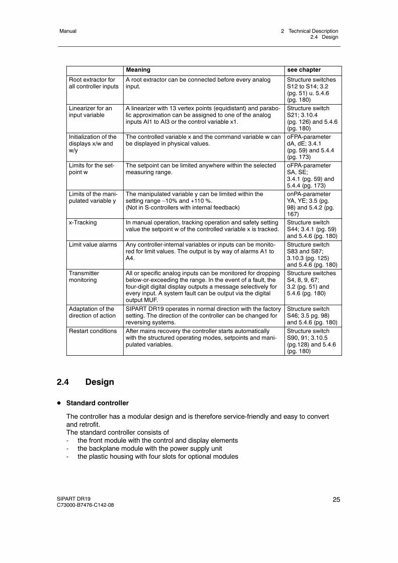
see chapterMeaning
Root extractor forall controller inputs
A root extractor can be connected before every analoginput.
Structure switchesS12 to S14; 3.2(pg. 51) u. 5.4.6(pg. 180)
Linearizer for aninput variable
A linearizer with 13 vertex points (equidistant) and parabo-lic approximation can be assigned to one of the analoginputs AI1 to AI3 or the control variable x1.
Structure switchS21; 3.10.4(pg. 126) and 5.4.6(pg. 180)
Initialization of thedisplays x/w andw/y
The controlled variable x and the command variable w canbe displayed in physical values.
oFPA-parameterdA, dE; 3.4.1(pg. 59) and 5.4.4(pg. 173)
Limits for the set-point w
The setpoint can be limited anywhere within the selectedmeasuring range.
oFPA-parameterSA, SE;3.4.1 (pg. 59) and5.4.4 (pg. 173)
Limits of the mani-pulated variable y
The manipulated variable y can be limited within thesetting range –10% and +110 %.(Not in S-controllers with internal feedback)
onPA-parameterYA, YE; 3.5 (pg.98) and 5.4.2 (pg.167)
x-Tracking In manual operation, tracking operation and safety settingvalue the setpoint w of the controlled variable x is tracked.
Structure switchS44; 3.4.1 (pg. 59)and 5.4.6 (pg. 180)
Limit value alarms Any controller-internal variables or inputs can be monito-red for limit values. The output is by way of alarms A1 toA4.
Structure switchS83 and S87;3.10.3 (pg. 125)and 5.4.6 (pg. 180)
Transmittermonitoring
All or specific analog inputs can be monitored for droppingbelow-or-exceeding the range. In the event of a fault, thefour-digit digital display outputs a message selectively forevery input. A system fault can be output via the digitaloutput MUF.
Structure switchesS4, 8, 9, 67;3.2 (pg. 51) and5.4.6 (pg. 180)
Adaptation of thedirection of action
SIPART DR19 operates in normal direction with the factorysetting. The direction of the controller can be changed forreversing systems.
Structure switchS46; 3.5 pg. 98)and 5.4.6 (pg. 180)
Restart conditions After mains recovery the controller starts automaticallywith the structured operating modes, setpoints and mani-pulated variables.
Structure switchS90, 91; 3.10.5(pg.128) and 5.4.6(pg. 180)
2.4 Design
D Standard controller
The controller has a modular design and is therefore service-friendly and easy to convertand retrofit.The standard controller consists of- the front module with the control and display elements- the backplane module with the power supply unit- the plastic housing with four slots for optional modules
2 Technical Description2.4 Design
Manual
26 SIPART DR19C73000-B7476-C142-08
D Front module
The front module accommodates the control and display elements, the CPU (CentralProcessing Unit) and the connectors for the backplane and options modules.
It is operated by a membrane keyboard with IP64 degree of protection. The striking colors ofthe operating keys effectively increases the operating reliability.
SIPART DR19 is equipped with a four-digit digital display for the controlled variable x and anadditional 4-digit digital display for the setpoint w, switchable to the manipulated variable y oralarm display. The comfortable analog display for the control difference (can be switched toother controlled variables with structure switch S89) as well as various status displays alsocontribute to a better process observation.
The measuring point label is changeable.
D Backplane module with power supply unit
The following signal connections are accessible through the backplane.- 1 Analog input AI1 potential-bound to M, for mV, RTD, TC, R
with measuring range also mA and V.- 1 analog output AO, potential-bound to GND, 0/4 to 20 mA- 2 Digital outputs +Δy, -Δy, potential-free via 230 V relay contacts- 2 Digital inputs DI1, DI2, for 24V-logic, function can be set- 2 Digital outputs DO1, DO2, for 24V-logic, function and direction can be set- 1 Voltage output L+ to the transmitter supply
The power supply is located in a die-cast housing on the backplane module. The heat loss istransferred to the back of the controller by cooling fins.
A DIN rail can be mounted for connecting a powerful coupling relay module.
The power supply unit is powerful and offers a total 200 mA external current for:- Supplying the analog output (0/4 to 20 mA)- Active digital outputs (up to 7 digital outputs)- L+-output for supplying two-wire transmitters
D Connection technique
The power supply is connected- for 230 V/115 V AC by a three-pin plug- for 24 V UC by a special two-pin plug.
On the standard controller the field lines (signal cables) are connected to three functionallycombined plug-in screw-type terminals.
The options modules for analog inputs and digital inputs- and outputs have their ownterminals which are also designed as plug-in screw-type terminals.The interface module is connected by its own plug.
2 Technical Description2.4 Design
Manual
SIPART DR19C73000-B7476-C142-08
27
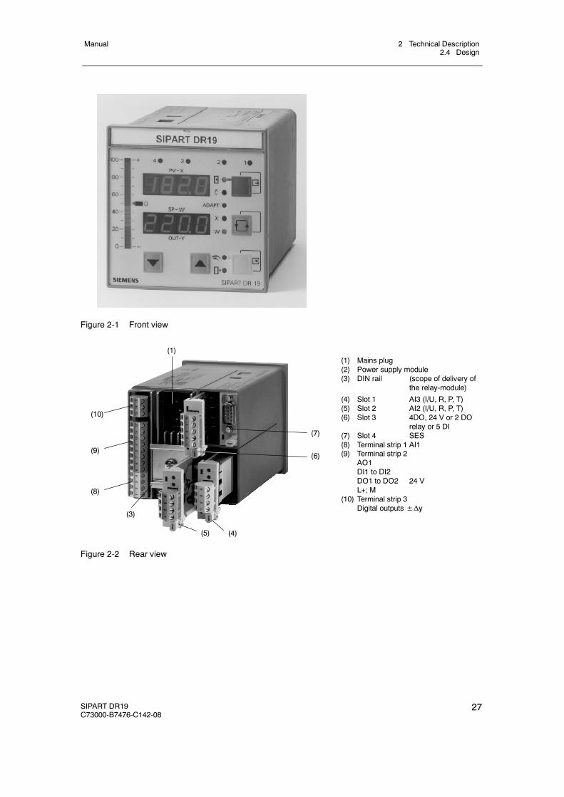
Figure 2-1 Front view
(1)
(7)
(6)
(10)
(9)
(8)
(3)
(5) (4)
(1) Mains plug(2) Power supply module(3) DIN rail (scope of delivery of
the relay-module)
(4) Slot 1 AI3 (I/U, R, P, T)(5) Slot 2 AI2 (I/U, R, P, T)(6) Slot 3 4DO, 24 V or 2 DO
relay or 5 DI(7) Slot 4 SES(8) Terminal strip 1 AI1(9) Terminal strip 2
AO1DI1 to DI2DO1 to DO2 24 VL+; M
(10) Terminal strip 3Digital outputs±Δy
Figure 2-2 Rear view
2 Technical Description2.5 Mode of Operation
Manual
28 SIPART DR19C73000-B7476-C142-08
2.5 Mode of Operation
2.5.1 Standard controller
D General
The SIPART DR19 controller operates based on a modern, highly integrated microcontrollerin CMOS technology. A large number of functions for controlling processing plants arestored in the instrument’s ROM. The user can adapt the controller to the task himself byconfiguring it.
D Analog input AI1
Measured value sensors such as thermocouples (TC), resistance thermometers Pt100(RTD), resistance potentiometers (R) or voltage transmitters in the mV range (mV) can beconnected directly to analog input AI1 of the SIPART DR19. The input variables I (0/4 to20 mA) and U (0/2 to 10 V) are converted to measuring range 0/20 to 100 mV by themeasuring range plug 6DR2805-8J and measured in the mV signal range. Type of sensor,type of connection, type of thermocouple and measuring range can be set by the structureswitches S4 to S7 and the menu CAE1. The sensor-specific characteristics (linearization) forthermocouples and Pt100-resistance thermometers are stored in the contoller’s programmemory and are automatically taken into account.
The signal lines are connected by a plug terminal block with screw-type terminals. Whenusing thermocouples with internal reference point, this terminal block must be replaced bythe terminal 6DR2805-8A. With the measuring range plug 6DR2805-8J in place of the ter-minal block, the measuring range of the direct input (0/20 to 100 mV) can be extended to0/2 to 10 V or 0/4 to 20 mA.
The measuring input has an AD converter with 18 bit resolution. The input is potentialbound. The feed current can be switched over at measuring variable resistance/resistancepotentiometer for better resolution.
D Outputs for the manipulated variable Y
The standard controller has the following outputs:
K-output: switchable between 0 or 4 to 20 mA, potential-bound
S-output: two relays, NOC, interlocked in factory setting, built-in spark quenchingdesigned for wiring with medium contactors. Other functions can beassigned to the relay outputs by configuration (structure switches S58 toS69), e.g. manipulated variable output±Δy in S-controller.
D Digital outputs DO1 and DO2
The digital outputs are short-circuit-proof and can drive commercially available relays or theinterface relays 6DR2804-8A/8B directly. Various functions can be assigned to the digitaloutputs by configuration (structure switches S58 to S69).
2 Technical Description2.5 Mode of Operation
Manual
SIPART DR19C73000-B7476-C142-08
29
D Digital inputs DI1 and DI2
The inputs are designed in 24 V logic and potential-bound. The function is assigned to theinput by configuring the controller (structure switches S23 to S34).
D CPU
The used microcontroller has integrated AD and DA converters and watchdog circuits for thecycle monitoring. The processor operates with a 64k EPROM (on a socket and thereforereplaceable) and a 1k RAM.
The program of the SIPART DR19 runs with a fixed cycle time of 100 ms. A process imageis generated at the start of every routine. The analog- and digital inputs, the operation of thefront keyboard and the process variables received by the serial interface are acquired oraccepted. All calculations are made according to the stored functions with these input sig-nals. Then output to the display elements, the analog outputs and the digital outputs andstorage of the calculated variables for transmission mode of the serial interface take place.In S-controllers, the program run is interrupted every 1.1 ms to be able to switch off theS-outputs for better resolution. The interface traffic also runs in interrupt mode.
D Power supply unit
A cast, overload-protected mains transformer for 115 V or 230 V AC built into a heat sink ora primary clocked plug-in type power supply unit for 24 V UC built into a heat sink generatesthe secondary internal supply voltages +24 V, +5 V and Uref from the power supply. Themetal body contacts a PE conductor (protection class I).The power supply and internal supply voltages are isolated from each other by safe separ-ation.The internal supply voltages are function low voltages.Since no further voltages are generated in the instrument, these statements apply for all fieldsignal lines with the exception of the relay leads (used standards, see chapter 2.6 “Technicaldata”, page 37).
D Configuration
The controller has a large number of prepared functions for controlling processing plants.The user programs the instrument himself by selecting the desired functions or setting para-meters by setting structure switches. The total functioning of the instrument is given by thecombination of the individual structure switches or parameter settings. No programmingknowledge is necessary (chapter 5, page 159).
All settings are made exclusively on the front control panel of the SIPART DR19 or the serialinterface.
The job-specific program written in this way is saved in the non-volatile user programmemory.
The instrument is configured as a fixed value controller in the factory setting. This settingcan be restored with the “APSt” function at any time.
2 Technical Description2.5 Mode of Operation
Manual
30 SIPART DR19C73000-B7476-C142-08
The following parameterization and structuring modes are available for configuring theSIPART DR19 controller.
onPA The transmission properties of the controller and with these the process courseare determined with the online-parameters. They can be changed during controloperation (online)
oFPA The offline-parameters determine the basic functions such as display elements,limit values, safety values. The controller is blocked (offline) while they are beingset, the last value of the manipulated variable is held.
StrS The instrument structure, e.g. fixed value controller or follow-up controller isdetermined with the structure switches. The controller is blocked (offline) whilethey are being set, the last value of the manipulated variable is held.
CAE1 The measuring range is set and fine adjustment made if necessary here for theanalog input AI1.
APSt The all preset-function restores the factory setting.
(AdAP) In the adaptation level the output conditions for automatic adaptation of thecontroller parameters to the process is preset and adaptation started.
(CLPA) The timing program is defined with the CLPA parameters. Release of theCLPA-menu with structure switch S1 = 5.
(CAE3) The measuring range is set and fine adjustment made if necessary here for theUNI-module.The CAE3-menu is only displayed if it has been released in the structuring level(structure switch S6>3).
2 Technical Description2.5 Mode of Operation
Manual
SIPART DR19C73000-B7476-C142-08
31
2.5.2 Options modules
The following option modules are described in this chapter
6DR2800-8J I/U-module6DR2800-8R R-module6DR2800-8V UNI-module6DR2805-8A Reference point6DR2805-8J Measuring range plug6DR2801-8D Module with 2 DO (relay)6DR2801-8E Module with 2 DI and 4 DO6DR2801-8C Module with 5 DI6DR2803-8P Serial interface PROFIBUS-DP6DR2803-8C Serial interface RS 232/RS 4856DR2804-8A Module with 4 DO relay6DR2804-8B Module with 2 DO relays
For information about the option cards 6DR2800--8P Pt100 Input (RTD) and 6DR2800--8T Ther-mocouple input (TC) please refer to our supplement sheet A5E00097041, internet addresswww.fielddevices.com.
6DR2800-8J I/U-module
D Input variables current 0/4 to 20 mA or voltage 0/0.2 to 1 V or 0/2 to 10 V
The module’s input amplifier is designed as a differentiating amplifier with shuntable gain for0 to 1 V or 0 to 10 V input signal. For current input signals the 49.9 Ω 0.1 % impedance isswitched on by plug-in bridges on the module. The start value 0 mA or 4 mA or 0 V or 0.2 V(2 V) is defined by configuration in the standard controller. The differentiating amplifier isdesigned for common mode voltages up to 10 V and has a high common mode suppression.As a result it is possible to connect the current inputs in series as for electrical isolation whenthey have common ground. For voltage inputs this circuit technique makes it possible to sup-press the voltage drops on the ground conductor by two-pole wiring on potential-bound volt-age sources. One refers to an electronic potential isolation (see chapter 4.2.3.2, page 147).
6DR2800-8R R-module
D Input for resistance or current potentiometer
Potentiometers with rated values of 80 Ω to 1200 Ω can be connected as resistance poten-tiometers. A constant current of Is = 5 mA is fed to the potentiometer wiper. The wiper resis-tance is therefore not included in the measurement. Resistors are switched parallel to thepotentiometer by settings on the module and a rough range selection made. Start of scaleand full scale are set with the two adjusting pots on the back of the module.
This fine adjustment can be made on the displays on the front module (if structured appropri-ately). For adjustment with a remote measuring instrument, the analog output can beassigned to the appropriate input.
The external wiring must be changed for resistance transmitters which cannot withstand the5 mA wiper current or which have a rated resistance >1 kΩ. The constant current is then notfed through the wiper but through the whole resistance network of the potentiometer. A volt-
2 Technical Description2.5 Mode of Operation
Manual
32 SIPART DR19C73000-B7476-C142-08
age divider measurement is now made through the wiper. Coarse adjustment is made by aremote parallel resistor to the resistance potentiometer.
This module can also be used as a current input with adjustable range start and full scale.The load is 49.9 Ω and is referenced to ground.
6DR2800-8V UNI-module
D Direct connection of thermocouple or Pt100-sensors, resistance or mV transmitters
Measured value sensors such as thermocouples (TC), resistance thermometers Pt100(RTD), resistance potentiometers (R) or voltage transmitters in the mV-range can beconnected directly. The measuring variable is selected by configuring the controller in theStrS-level (structure switches S7, S9, S10 and S11); the measuring range and the otherparameters are set in the CAE3-menu. The sensor-specific characteristics (linearization) forthermocouples and Pt100-resistance thermometers are stored in the contoller’s programmemory and are automatically taken into account. No settings need to be made on themodule itself.
The signal lines are connected by a plug terminal block with screw-type terminals. Whenusing thermocouples with internal reference point, this terminal block must be replaced bythe terminal 6DR2805-8A. With the measuring range plug 6DR2805-8J in place of theterminal block, the measuring range of the direct input (0/20 to 100 mV) can be extended to0/2 to 10 V or 0/4 to 20 mA.
The UNI-module operates with an AD-converter with 18 bit resolution. The measuring inputsand ground of the standard controller are electrically isolated with a permissible commonmode voltage of 50 V UC.
The UNI-module can only be used at slot 1 (AI3).
6DR2805-8A reference point
D Terminal with internal reference point for thermocouples
This terminal is used in connection with the analog input AI1 or in connection with the UNImodule for temperature measuring with thermocouples with internal reference point. It con-sists of a temperature sensor which is pre-assembled on a terminal block and plated toavoid mechanical damage.
6DR2805-8J measuring range plug
D Measuring range plug for current 0/4 to 20 mA or voltage 0/2 to 10 V
The measuring range plug is used in connection with the analog input AI1 or in connectionwith the UNI module for measuring current and voltage. The input variable is reduced to 0/20to 100 mV by a voltage divider or shunt resistors in the measuring range plug.
Wiper resistors with 250 Ω or 50 Ω are available optionally at 2 different terminals for 0/4 to20 mA signals.
The electrical isolation of the UNI-module is retained even when the measuring range plug isused.
2 Technical Description2.5 Mode of Operation
Manual
SIPART DR19C73000-B7476-C142-08
33
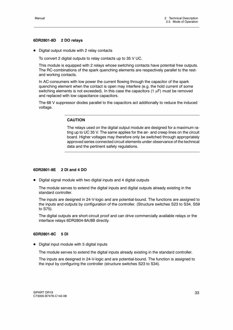
6DR2801-8D 2 DO relays
D Digital output module with 2 relay contacts
To convert 2 digital outputs to relay contacts up to 35 V UC.
This module is equipped with 2 relays whose switching contacts have potential free outputs.The RC-combinations of the spark quenching elements are respectively parallel to the rest-and working contacts.
In AC-consumers with low power the current flowing through the capacitor of the sparkquenching element when the contact is open may interfere (e.g. the hold current of someswitching elements is not exceeded). In this case the capacitors (1 μF) must be removedand replaced with low capacitance capacitors.
The 68 V suppressor diodes parallel to the capacitors act additionally to reduce the inducedvoltage.
CAUTION
The relays used on the digital output module are designed for a maximum ra-ting up to UC 35 V. The same applies for the air- and creep lines on the circuitboard. Higher voltages may therefore only be switched through appropriatelyapproved series connected circuit elements under observance of the technicaldata and the pertinent safety regulations.
6DR2801-8E 2 DI and 4 DO
D Digital signal module with two digital inputs and 4 digital outputs
The module serves to extend the digital inputs and digital outputs already existing in thestandard controller.
The inputs are designed in 24-V-logic and are potential-bound. The functions are assigned tothe inputs and outputs by configuration of the controller. (Structure switches S23 to S34, S59to S75).
The digital outputs are short-circuit proof and can drive commercially available relays or theinterface relays 6DR2804-8A/8B directly.
6DR2801-8C 5 DI
D Digital input module with 5 digital inputs
The module serves to extend the digital inputs already existing in the standard controller.
The inputs are designed in 24-V-logic and are potential-bound. The function is assigned tothe input by configuring the controller (structure switches S23 to S34).
2 Technical Description2.5 Mode of Operation
Manual
34 SIPART DR19C73000-B7476-C142-08
6DR2803-8P Serial interface PROFIBUS-DP
The 6DR2803-8P module is a PROFIBUS-DP-interface module with RS-485-driver and electri-cal isolation from the instrument. It operates as an intelligent converter module and adapts theprivate SIPART- to the open PROFIBUS-DP-protocol.
This options card can be used in all SIPART-DR-instruments in slot 4. The following settingsmust be made with the appropriate structure switches for the serial interfaces.
- Interface on (if possible)- Even parity- LRC without- Baud rate 9600- Parameters/process values writable (as desired)- Station number of choice 0 to 125
Make sure that the station number is not assigned double on the bus. The PROFIBUS-moduleserves to connect the SIPART-controllers to a master system for control and monitoring. Inaddition the parameters and structure switches of the controller can be read and written. Up to32 process variables can be selected and read out cyclically by configuration of the PROFI-BUS-module.
The process data are read out of the controller in a polling procedure with an update time<300 ms. If the master write process data to the slave, these become active after a maximum 1controller cycle.
A description of the PROFIBUS interface including the basic device data (*.GSD) is available inInternet for interpreting the signals and useful data from and to the SIPART controller for creat-ing a master-slave coupling software;Internet address: www.fielddevices.com [Edition: 05.2000]
The SIPART S5 DP and SIPART S7 DP programs are offered for DP-masters SIMATIC S5 andS7.
2 Technical Description2.5 Mode of Operation
Manual
SIPART DR19C73000-B7476-C142-08
35
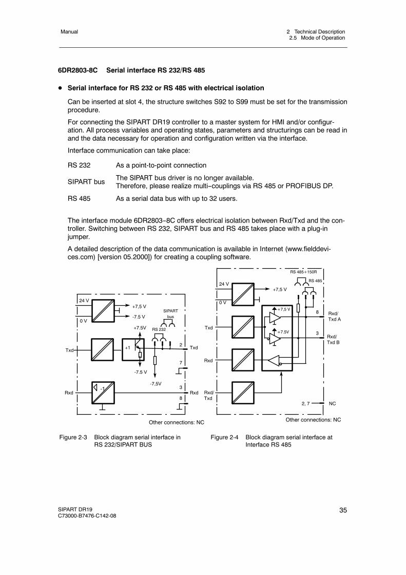
6DR2803-8C Serial interface RS 232/RS 485
D Serial interface for RS 232 or RS 485 with electrical isolation
Can be inserted at slot 4, the structure switches S92 to S99 must be set for the transmissionprocedure.
For connecting the SIPART DR19 controller to a master system for HMI and/or configur-ation. All process variables and operating states, parameters and structurings can be read inand the data necessary for operation and configuration written via the interface.
Interface communication can take place:
RS 232 As a point-to-point connection
SIPART bus The SIPART bus driver is no longer available.Therefore, please realize multi--couplings via RS 485 or PROFIBUS DP.
RS 485 As a serial data bus with up to 32 users.
The interface module 6DR2803--8C offers electrical isolation between Rxd/Txd and the con-troller. Switching between RS 232, SIPART bus and RS 485 takes place with a plug-injumper.
A detailed description of the data communication is available in Internet (www.fielddevi-ces.com) [version 05.2000]) for creating a coupling software.
Rxd/Txd B
Rxd/Txd A
24 V
0 V
Txd
Rxd-1
+1
+7,5 V
-7.5 V
+7.5V
-7.5 V
-7,5V
Rxd
Txd2
3
7
8
Other connections: NC
24 V
0 V
Txd
Rxd
Other connections: NC
Rxd/Txd
3
NC2, 7
8
+7,5 V
+7,5 V
+7.5V
SIPARTbus
RS 485
RS 485+150R
RS 232
Figure 2-3 Block diagram serial interface inRS 232/SIPART BUS
Figure 2-4 Block diagram serial interface atInterface RS 485
2 Technical Description2.5 Mode of Operation
Manual
36 SIPART DR19C73000-B7476-C142-08
6DR2804-8A module with 4 DO-relays6DR2804-8B module with 2 DO-relays
D Coupling relay module with 2 or 4 relays
To convert 2 or 4 binary outputs to relay contacts up to 230 V UC.
The relays can be snapped onto a mounting rail on the back of the controller. The mountingrail is delivered with the coupling relay module.
One or two relay modules are installed per version. Each of these modules consists of tworelays with quench diodes parallel to the control winding. Every relay has a switching contactwith spark quenching in both switching branches. In AC-consumers with a very low power,the current flowing (e.g. hold current in contactors) through the spark quenching capacitor(33nF) when the contact is open interferes. In this case they should be replaced by capaci-tors of the same construction type, voltage strength and lower value.
The switching contact is connected to the plug-in terminals at three poles so that idle currentand operating current circuits can be switched. The relays can be controlled directly from thecontroller’s digital outputs by external wiring.
! CAUTION
The relays used on the interface relaymodule are designed for a maximum ra-ting of AC 250 V in overvoltage class III and contamination factor 2 accordingto DIN EN 61010 Part 1.The same applies for the air- and creep lines on the circuit board.Resonance increases up to double the ratedoperating voltagemayoccurwhenphase shift motors are controlled. These voltages are available at the openrelay contact. Therefore suchmotorsmay only be controlled under observanceof the technical data and the pertinent safety conditions via approved switchingelements.
2 Technical Description2.6 Technical Data
Manual
SIPART DR19C73000-B7476-C142-08
37
2.6 Technical Data
2.6.1 General data
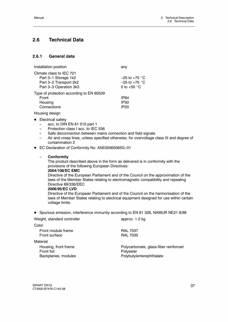
Installation position any
Climate class to IEC 721Part 3--1 Storage 1k2Part 3--2 Transport 2k2Part 3--3 Operation 3k3
--25 to +75 _C--25 to +75 _C0 to +50 _C
Type of protection according to EN 60529FrontHousingConnections
IP64IP30IP20
Housing design
D Electrical safety-- acc. to DIN EN 61 010 part 1-- Protection class I acc. to IEC 536-- Safe disconnection between mains connection and field signals-- Air and creep lines, unless specified otherwise, for overvoltage class III and degree of
contamination 2D EC Declaration of Conformity No. A5E00065065G--01
-- ConformityThe product described above in the form as delivered is in conformity with theprovisions of the following European Directives:2004/108/EC EMCDirective of the European Parliament and of the Council on the approximation of thelaws of the Member States relating to electromagnetic compatibility and repealingDirective 89/336/EEC2006/95/EC LVDDirective of the European Parliament and of the Council on the harmonisation of thelaws of Member States relating to electrical equipment designed for use within certainvoltage limits.
D Spurious emission, interference immunity according to EN 61 326, NAMUR NE21 8/98
Weight, standard controller approx. 1.2 kg
ColorFront module frameFront surface
RAL 7037RAL 7035
MaterialHousing, front frameFront foilBackplanes, modules
Polycarbonate, glass-fiber reinforcedPolyesterPolybutylenterephthalate
2 Technical Description2.6 Technical Data
Manual
38 SIPART DR19C73000-B7476-C142-08
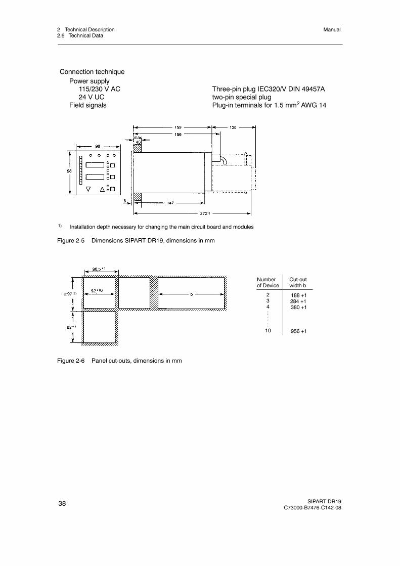
Connection techniquePower supply
115/230 V AC24 V UC
Field signals
Three-pin plug IEC320/V DIN 49457Atwo-pin special plugPlug-in terminals for 1.5 mm2 AWG 14
1) Installation depth necessary for changing the main circuit board and modules
Figure 2-5 Dimensions SIPART DR19, dimensions in mm
Number Cut-outof Device width b
234:::10
188 +1284 +1380 +1
956 +1
Figure 2-6 Panel cut-outs, dimensions in mm
2 Technical Description2.6 Technical Data
Manual
SIPART DR19C73000-B7476-C142-08
39
2.6.2 Standard controller
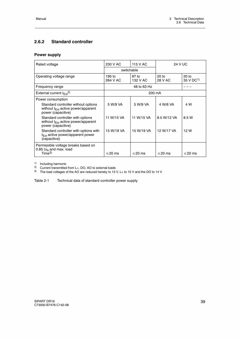
Power supply
Rated voltage 230 V AC 115 V AC 24 V UCg
switchable
Operating voltage range 195 to264 V AC
97 to132 V AC
20 to28 V AC
20 to35 V DC1)
Frequency range 48 to 63 Hz -- -- --
External current IExt2) 200 mA
Power consumptionStandard controller without optionswithout IExt active power/apparentpower (capacitive)Standard controller with optionswithout IExt active power/apparentpower (capacitive)Standard controller with options withIExt active power/apparent power(capacitive)
5 W/9 VA
11 W/15 VA
15 W/19 VA
5 W/9 VA
11 W/15 VA
15 W/19 VA
4 W/6 VA
8.5 W/12 VA
12 W/17 VA
4 W
8.5 W
12 W
Permissible voltage breaks based on0.85 UN and max. load
Time3) ≤20 ms ≤20 ms ≤20 ms ≤20 ms
1) Including harmonic2) Current transmitted from L+, DO, AO to external loads3) The load voltages of the AO are reduced hereby to 13 V, L+ to 15 V and the DO to 14 V
Table 2-1 Technical data of standard controller power supply
2 Technical Description2.6 Technical Data
Manual
40 SIPART DR19C73000-B7476-C142-08
Analog input AI1
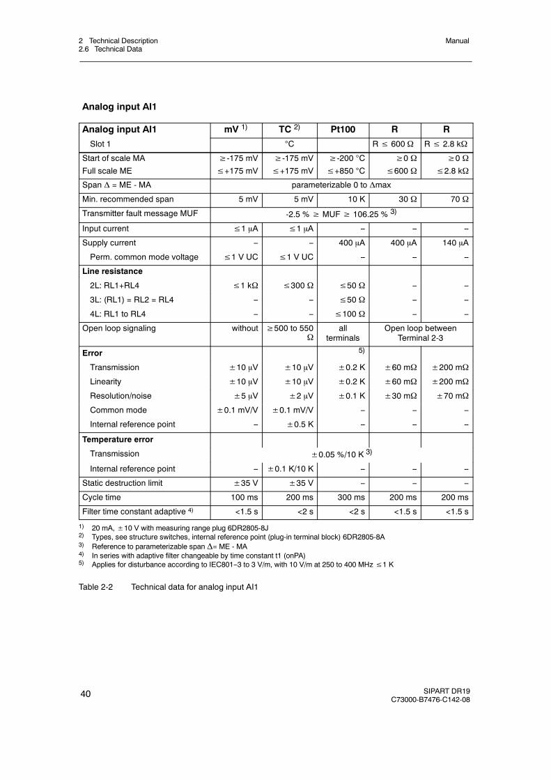
Analog input AI1 mV 1) TC 2) Pt100 R R
Slot 1 C R≤ 600 Ω R≤ 2.8 kΩ
Start of scale MA
Full scale ME
≥-175 mV≤+175 mV
≥-175 mV≤+175 mV
≥-200 C
≤+850 C
≥0 Ω≤600 Ω
≥0 Ω≤2.8 kΩ
Span Δ = ME - MA parameterizable 0 to Δmax
Min. recommended span 5 mV 5 mV 10 K 30 Ω 70 Ω
Transmitter fault message MUF -2.5 %≥ MUF≥ 106.25 % 3)
Input current ≤1 μA ≤1 μA -- -- --
Supply current -- -- 400 μA 400 μA 140 μA
Perm. common mode voltage ≤1 V UC ≤1 V UC -- -- --
Line resistance
2L: RL1+RL4 ≤1 kΩ ≤300 Ω ≤50 Ω -- --
3L: (RL1) = RL2 = RL4 -- -- ≤50 Ω -- --
4L: RL1 to RL4 -- -- ≤100 Ω -- --
Open loop signaling without ≥500 to 550Ω
allterminals
Open loop betweenTerminal 2-3
Error 5)
Transmission ±10 μV ±10 μV ±0.2 K ±60 mΩ ±200 mΩ
Linearity ±10 μV ±10 μV ±0.2 K ±60 mΩ ±200 mΩ
Resolution/noise ±5 μV ±2 μV ±0.1 K ±30 mΩ ±70 mΩ
Common mode ±0.1 mV/V ±0.1 mV/V -- -- --
Internal reference point -- ±0.5 K -- -- --
Temperature error
Transmission ±0.05 %/10 K 3)
Internal reference point -- ±0.1 K/10 K -- -- --
Static destruction limit ±35 V ±35 V -- -- --
Cycle time 100 ms 200 ms 300 ms 200 ms 200 ms
Filter time constant adaptive 4) <1.5 s <2 s <2 s <1.5 s <1.5 s
1) 20 mA,±10 V with measuring range plug 6DR2805-8J2) Types, see structure switches, internal reference point (plug-in terminal block) 6DR2805-8A3) Reference to parameterizable span Δ= ME - MA4) In series with adaptive filter changeable by time constant t1 (onPA)5) Applies for disturbance according to IEC801--3 to 3 V/m, with 10 V/m at 250 to 400 MHz≤1 K
Table 2-2 Technical data for analog input AI1
2 Technical Description2.6 Technical Data
Manual
SIPART DR19C73000-B7476-C142-08
41
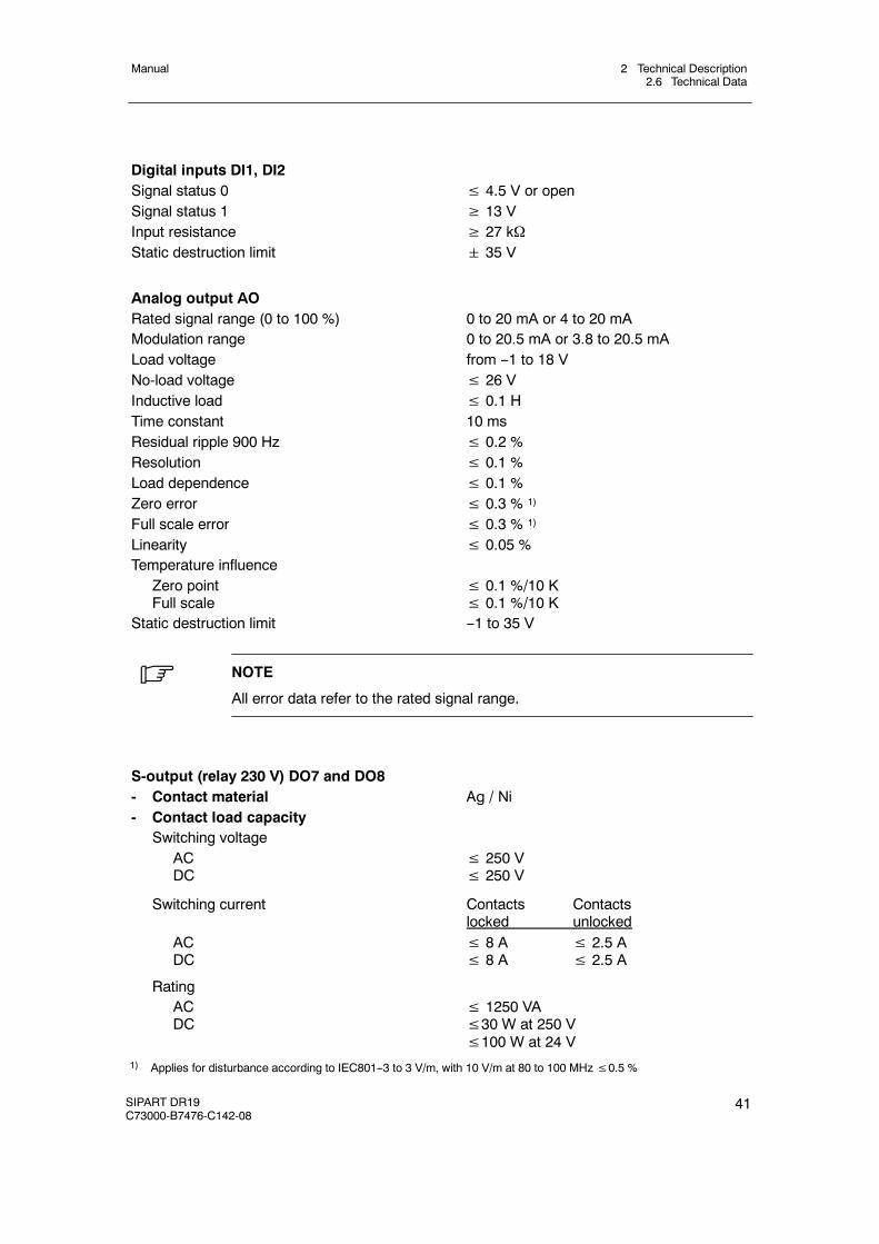
Digital inputs DI1, DI2Signal status 0 ≤ 4.5 V or openSignal status 1 ≥ 13 VInput resistance ≥ 27 kΩStatic destruction limit 35 V
Analog output AORated signal range (0 to 100 %) 0 to 20 mA or 4 to 20 mAModulation range 0 to 20.5 mA or 3.8 to 20.5 mALoad voltage from --1 to 18 VNo-load voltage ≤ 26 VInductive load ≤ 0.1 HTime constant 10 msResidual ripple 900 Hz ≤ 0.2 %Resolution ≤ 0.1 %Load dependence ≤ 0.1 %Zero error ≤ 0.3 % 1)
Full scale error ≤ 0.3 % 1)
Linearity ≤ 0.05 %Temperature influence
Zero pointFull scale
≤ 0.1 %/10 K≤ 0.1 %/10 K
Static destruction limit --1 to 35 V
. NOTE
All error data refer to the rated signal range.
S-output (relay 230 V) DO7 and DO8- Contact material Ag / Ni- Contact load capacity
Switching voltageACDC
≤ 250 V≤ 250 V
Switching current Contacts Contactslocked unlocked
ACDC
≤ 8 A ≤ 2.5 A≤ 8 A ≤ 2.5 A
RatingACDC
≤ 1250 VA≤30 W at 250 V≤100 W at 24 V
1) Applies for disturbance according to IEC801--3 to 3 V/m, with 10 V/m at 80 to 100 MHz≤0.5 %
2 Technical Description2.6 Technical Data
Manual
42 SIPART DR19C73000-B7476-C142-08
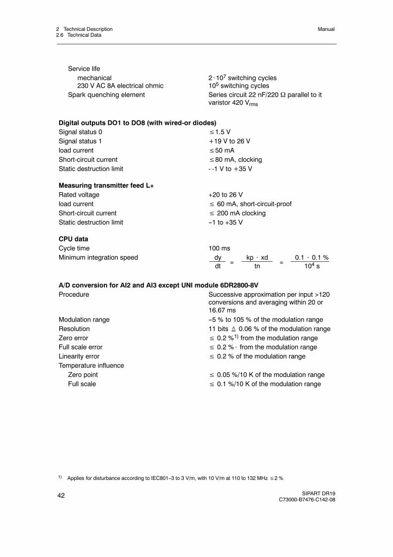
Service lifemechanical230 V AC 8A electrical ohmic
2⋅107 switching cycles105 switching cycles
Spark quenching element Series circuit 22 nF/220 Ω parallel to itvaristor 420 Vrms
Digital outputs DO1 to DO8 (with wired-or diodes)Signal status 0 ≤1.5 VSignal status 1 +19 V to 26 Vload current ≤50 mAShort-circuit current ≤80 mA, clockingStatic destruction limit - -1 V to +35 V
Measuring transmitter feed L+Rated voltage +20 to 26 Vload current ≤ 60 mA, short-circuit-proofShort-circuit current ≤ 200 mA clockingStatic destruction limit --1 to +35 V
CPU dataCycle time 100 msMinimum integration speed dy
dtkp ⋅ xd
tn0.1 ⋅ 0.1 %
104 s= =
A/D conversion for AI2 and AI3 except UNI module 6DR2800-8VProcedure Successive approximation per input >120
conversions and averaging within 20 or16.67 ms
Modulation range --5 % to 105 % of the modulation rangeResolution 11 bits≙ 0.06 % of the modulation rangeZero error ≤ 0.2 %1) from the modulation rangeFull scale error ≤ 0.2 %⋅ from the modulation rangeLinearity error ≤ 0.2 % of the modulation rangeTemperature influence
Zero point ≤ 0.05 %/10 K of the modulation rangeFull scale ≤ 0.1 %/10 K of the modulation range
1) Applies for disturbance according to IEC801--3 to 3 V/m, with 10 V/m at 110 to 132 MHz≤2 %
2 Technical Description2.6 Technical Data
Manual
SIPART DR19C73000-B7476-C142-08
43
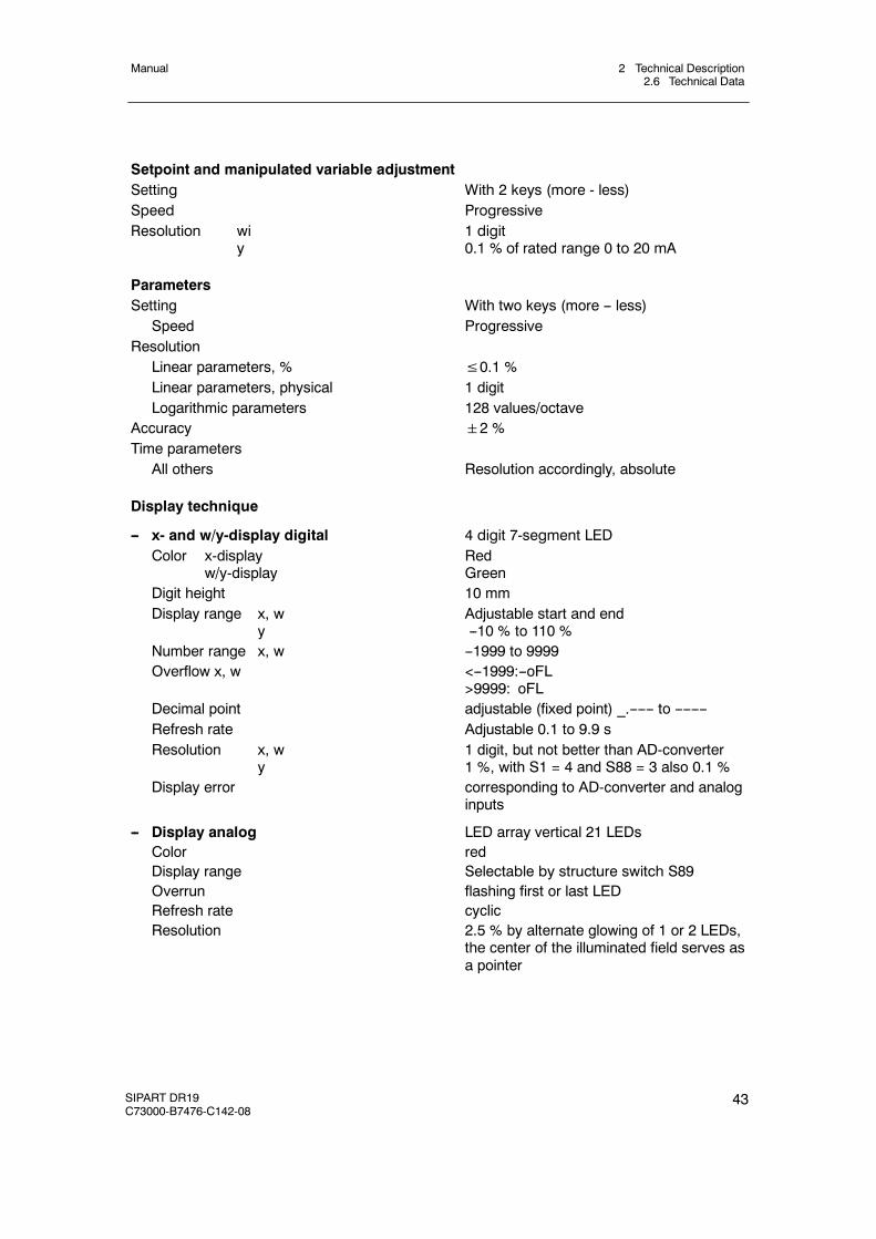
Setpoint and manipulated variable adjustmentSetting With 2 keys (more - less)Speed ProgressiveResolution wi
y1 digit0.1 % of rated range 0 to 20 mA
ParametersSetting With two keys (more -- less)
Speed ProgressiveResolution
Linear parameters, % ≤0.1 %Linear parameters, physical 1 digitLogarithmic parameters 128 values/octave
Accuracy 2 %Time parameters
All others Resolution accordingly, absolute
Display technique
-- x- and w/y-display digital 4 digit 7-segment LEDColor x-display
w/y-displayRedGreen
Digit height 10 mmDisplay range x, w
yAdjustable start and end--10 % to 110 %
Number range x, w --1999 to 9999Overflow x, w <--1999:--oFL
>9999: oFLDecimal point adjustable (fixed point) _.------ to --------Refresh rate Adjustable 0.1 to 9.9 sResolution x, w
y1 digit, but not better than AD-converter1 %, with S1 = 4 and S88 = 3 also 0.1 %
Display error corresponding to AD-converter and analoginputs
-- Display analog LED array vertical 21 LEDsColor redDisplay range Selectable by structure switch S89Overrun flashing first or last LEDRefresh rate cyclicResolution 2.5 % by alternate glowing of 1 or 2 LEDs,
the center of the illuminated field serves asa pointer
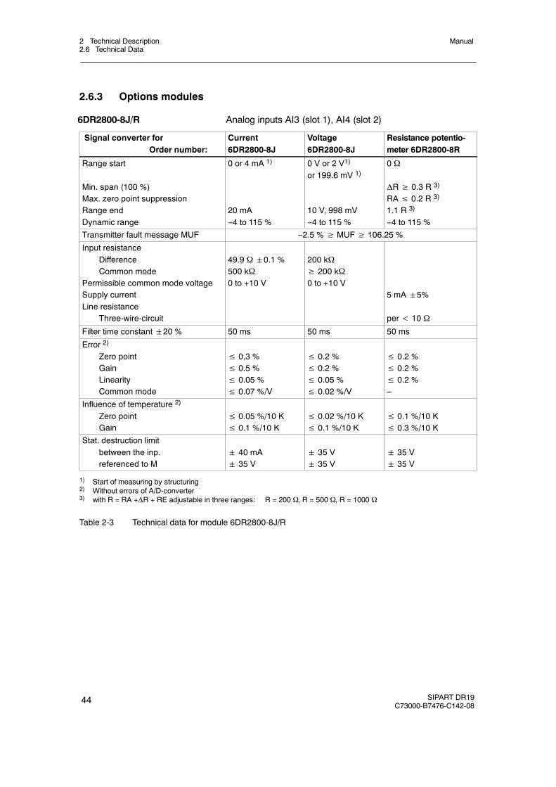
2 Technical Description2.6 Technical Data
Manual
44 SIPART DR19C73000-B7476-C142-08
2.6.3 Options modules
6DR2800-8J/R Analog inputs AI3 (slot 1), AI4 (slot 2)
Signal converter forOrder number:
Current6DR2800-8J
Voltage6DR2800-8J
Resistance potentio-meter 6DR2800-8R
Range start
Min. span (100 %)Max. zero point suppressionRange endDynamic range
0 or 4 mA 1)
20 mA--4 to 115 %
0 V or 2 V1)
or 199.6 mV 1)
10 V, 998 mV--4 to 115 %
0 Ω
ΔR≥ 0.3 R 3)
RA≤ 0.2 R 3)
1.1 R 3)
--4 to 115 %
Transmitter fault message MUF --2.5 %≥ MUF≥ 106.25 %
Input resistanceDifferenceCommon mode
Permissible common mode voltageSupply currentLine resistance
Three-wire-circuit
49.9 Ω0.1 %500 kΩ0 to +10 V
200 kΩ≥ 200 kΩ0 to +10 V
5 mA5%
per< 10 Ω
Filter time constant20 % 50 ms 50 ms 50 ms
Error 2)
Zero pointGainLinearityCommon mode
≤ 0,3 %≤ 0.5 %≤ 0.05 %≤ 0.07 %/V
≤ 0.2 %≤ 0.2 %≤ 0.05 %≤ 0.02 %/V
≤ 0.2 %≤ 0.2 %≤ 0.2 %--
Influence of temperature 2)
Zero pointGain
≤ 0.05 %/10 K≤ 0.1 %/10 K
≤ 0.02 %/10 K≤ 0.1 %/10 K
≤ 0.1 %/10 K≤ 0.3 %/10 K
Stat. destruction limitbetween the inp.referenced to M
40 mA 35 V
35 V 35 V
35 V 35 V
1) Start of measuring by structuring2) Without errors of A/D-converter3) with R = RA +ΔR + RE adjustable in three ranges: R = 200 Ω, R = 500 Ω, R = 1000 Ω
Table 2-3 Technical data for module 6DR2800-8J/R
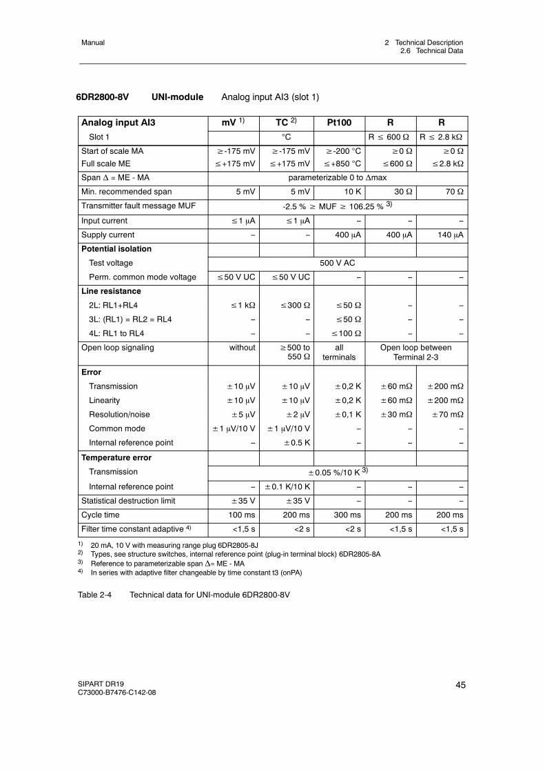
2 Technical Description2.6 Technical Data
Manual
SIPART DR19C73000-B7476-C142-08
45
6DR2800-8V UNI-module Analog input AI3 (slot 1)
Analog input AI3 mV 1) TC 2) Pt100 R R
Slot 1 C R≤ 600 Ω R≤ 2.8 kΩ
Start of scale MA
Full scale ME
≥-175 mV≤+175 mV
≥-175 mV≤+175 mV
≥-200 C
≤+850 C
≥0 Ω≤600 Ω
≥0 Ω≤2.8 kΩ
Span Δ = ME - MA parameterizable 0 to Δmax
Min. recommended span 5 mV 5 mV 10 K 30 Ω 70 Ω
Transmitter fault message MUF -2.5 %≥ MUF≥ 106.25 % 3)
Input current ≤1 μA ≤1 μA -- -- --
Supply current -- -- 400 μA 400 μA 140 μA
Potential isolation
Test voltage 500 V AC
Perm. common mode voltage ≤50 V UC ≤50 V UC -- -- --
Line resistance
2L: RL1+RL4 ≤1 kΩ ≤300 Ω ≤50 Ω -- --
3L: (RL1) = RL2 = RL4 -- -- ≤50 Ω -- --
4L: RL1 to RL4 -- -- ≤100 Ω -- --
Open loop signaling without ≥500 to550 Ω
allterminals
Open loop betweenTerminal 2-3
Error
Transmission ±10 μV ±10 μV ±0,2 K ±60 mΩ ±200 mΩ
Linearity ±10 μV ±10 μV ±0,2 K ±60 mΩ ±200 mΩ
Resolution/noise ±5 μV ±2 μV ±0,1 K ±30 mΩ ±70 mΩ
Common mode ±1 μV/10 V ±1 μV/10 V -- -- --
Internal reference point -- ±0.5 K -- -- --
Temperature error
Transmission ±0.05 %/10 K 3)
Internal reference point -- ±0.1 K/10 K -- -- --
Statistical destruction limit ±35 V ±35 V -- -- --
Cycle time 100 ms 200 ms 300 ms 200 ms 200 ms
Filter time constant adaptive 4) <1,5 s <2 s <2 s <1,5 s <1,5 s
1) 20 mA, 10 V with measuring range plug 6DR2805-8J2) Types, see structure switches, internal reference point (plug-in terminal block) 6DR2805-8A3) Reference to parameterizable span Δ= ME - MA4) In series with adaptive filter changeable by time constant t3 (onPA)
Table 2-4 Technical data for UNI-module 6DR2800-8V
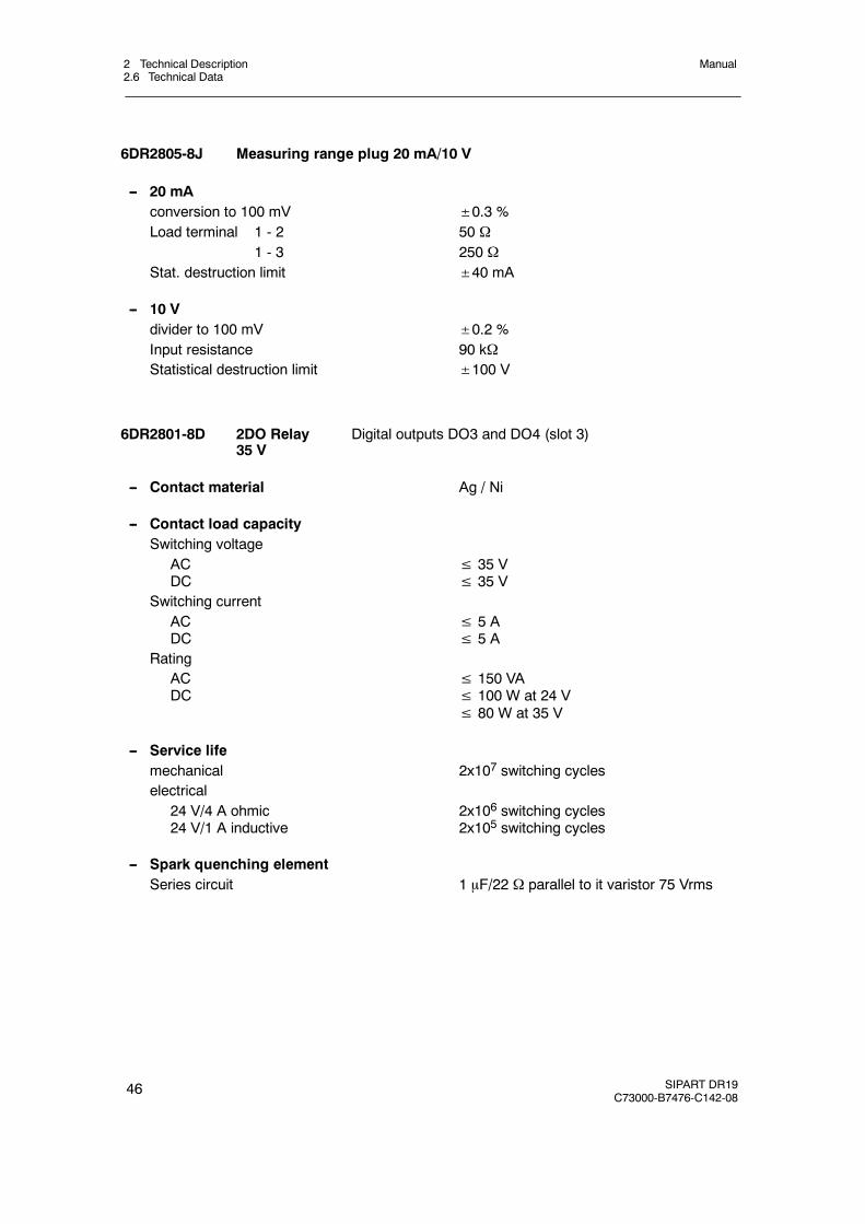
2 Technical Description2.6 Technical Data
Manual
46 SIPART DR19C73000-B7476-C142-08
6DR2805-8J Measuring range plug 20 mA/10 V
-- 20 mAconversion to 100 mV ±0.3 %Load terminal 1 - 2 50 Ω
1 - 3 250 ΩStat. destruction limit ±40 mA
-- 10 Vdivider to 100 mV ±0.2 %Input resistance 90 kΩStatistical destruction limit ±100 V
6DR2801-8D 2DO Relay35 V
Digital outputs DO3 and DO4 (slot 3)
-- Contact material Ag / Ni
-- Contact load capacitySwitching voltage
ACDC
≤ 35 V≤ 35 V
Switching currentACDC
≤ 5 A≤ 5 A
RatingACDC
≤ 150 VA≤ 100 W at 24 V≤ 80 W at 35 V
-- Service lifemechanical 2x10⁷ switching cycleselectrical
24 V/4 A ohmic24 V/1 A inductive
2x10⁶ switching cycles2x105 switching cycles
-- Spark quenching elementSeries circuit 1 μF/22 Ω parallel to it varistor 75 Vrms
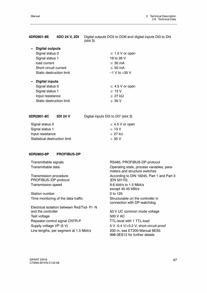
2 Technical Description2.6 Technical Data
Manual
SIPART DR19C73000-B7476-C142-08
47
6DR2801-8E 4DO 24 V, 2DI Digital outputs DO3 to DO6 and digital inputs DI3 to DI4(slot 3)
-- Digital outputsSignal status 0 ≤ 1.5 V or openSignal status 1 19 to 26 Vload current ≤ 30 mAShort-circuit current ≤ 50 mAStatic destruction limit --1 V to +35 V
-- Digital inputsSignal status 0 ≤ 4.5 V or openSignal status 1 ≥ 13 VInput resistance ≥ 27 kΩStatic destruction limit 35 V
6DR2801-8C 5DI 24 V Digital inputs DI3 to DI7 (slot 3)
Signal status 0 ≤ 4.5 V or openSignal status 1 ≥ 13 VInput resistance ≥ 27 kΩStatistical destruction limit ± 35 V
6DR2803-8P PROFIBUS-DP
Transmittable signals RS485, PROFIBUS-DP-protocolTransmittable data Operating state, process variables, para-
meters and structure switchesTransmission procedurePROFIBUS-/DP-protocol
According to DIN 19245, Part 1 and Part 3(EN 50170)
Transmission speed 9.6 kbit/s to 1.5 Mbit/sexcept 45.45 kBit/s
Station number 0 to 125Time monitoring of the data traffic Structurable on the controller in
connection with DP-watchdogElectrical isolation between Rxd/Txd- P/- Nand the controller 50 V UC common mode voltageTest voltage 500 V ACRepeater-control signal CNTR-P TTL-level with 1 TTL-loadSupply voltage VP (5 V) 5 V -0.4 V/+0.2 V; short-circuit-proofLine lengths, per segment at 1.5 Mbit/s 200 m, see ET200-Manual 6ES5
998-3ES12 for further details
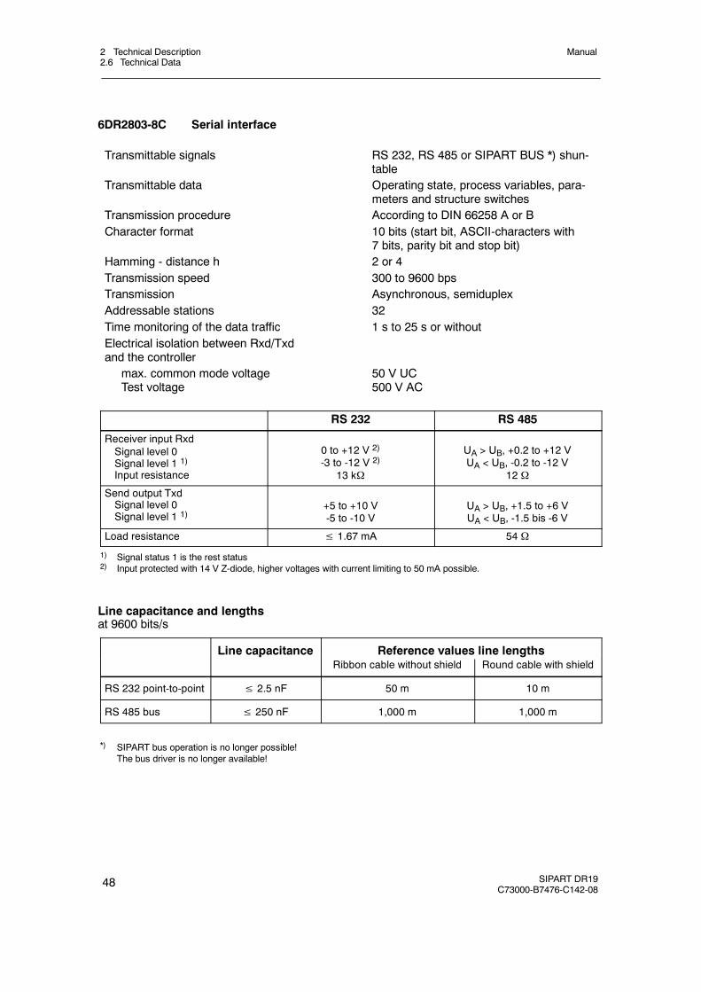
2 Technical Description2.6 Technical Data
Manual
48 SIPART DR19C73000-B7476-C142-08
6DR2803-8C Serial interface
Transmittable signals RS 232, RS 485 or SIPART BUS *) shun-table
Transmittable data Operating state, process variables, para-meters and structure switches
Transmission procedure According to DIN 66258 A or BCharacter format 10 bits (start bit, ASCII-characters with
7 bits, parity bit and stop bit)Hamming - distance h 2 or 4Transmission speed 300 to 9600 bpsTransmission Asynchronous, semiduplexAddressable stations 32Time monitoring of the data traffic 1 s to 25 s or withoutElectrical isolation between Rxd/Txdand the controller
max. common mode voltageTest voltage
50 V UC500 V AC
RS 232 RS 485
Receiver input RxdSignal level 0Signal level 1 1)
Input resistance
0 to +12 V 2)
-3 to -12 V 2)
13 kΩ
UA > UB, +0.2 to +12 VUA < UB, -0.2 to -12 V
12 Ω
Send output TxdSignal level 0Signal level 1 1)
+5 to +10 V-5 to -10 V
UA > UB, +1.5 to +6 VUA < UB, -1.5 bis -6 V
Load resistance ≤ 1.67 mA 54 Ω
1) Signal status 1 is the rest status2) Input protected with 14 V Z-diode, higher voltages with current limiting to 50 mA possible.
Line capacitance and lengthsat 9600 bits/s
Line capacitance Reference values line lengthspRibbon cable without shield Round cable with shield
RS 232 point-to-point ≤ 2.5 nF 50 m 10 m
RS 485 bus ≤ 250 nF 1,000 m 1,000 m
*) SIPART bus operation is no longer possible!The bus driver is no longer available!
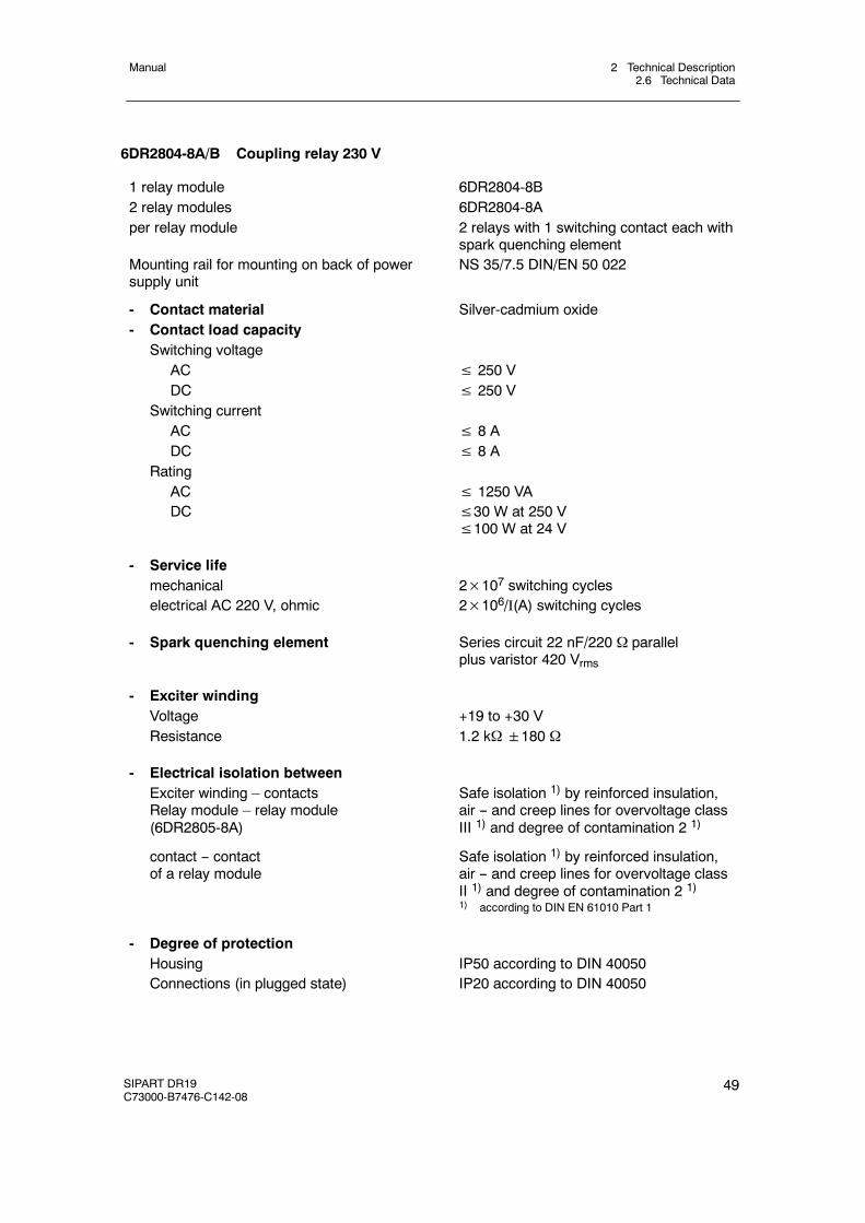
2 Technical Description2.6 Technical Data
Manual
SIPART DR19C73000-B7476-C142-08
49
6DR2804-8A/B Coupling relay 230 V
1 relay module 6DR2804-8B2 relay modules 6DR2804-8Aper relay module 2 relays with 1 switching contact each with
spark quenching elementMounting rail for mounting on back of powersupply unit
NS 35/7.5 DIN/EN 50 022
- Contact material Silver-cadmium oxide- Contact load capacity
Switching voltageAC ≤ 250 VDC ≤ 250 V
Switching currentAC ≤ 8 ADC ≤ 8 A
RatingAC ≤ 1250 VADC ≤30 W at 250 V
≤100 W at 24 V
- Service lifemechanical 2×10⁷ switching cycleselectrical AC 220 V, ohmic 2×10⁶/I(A) switching cycles
- Spark quenching element Series circuit 22 nF/220 Ω parallelplus varistor 420 Vrms
- Exciter windingVoltage +19 to +30 VResistance 1.2 kΩ180 Ω
- Electrical isolation betweenExciter winding – contactsRelay module – relay module(6DR2805-8A)
Safe isolation 1) by reinforced insulation,air -- and creep lines for overvoltage classIII 1) and degree of contamination 2 1)
contact -- contactof a relay module
Safe isolation 1) by reinforced insulation,air -- and creep lines for overvoltage classII 1) and degree of contamination 2 1)1) according to DIN EN 61010 Part 1
- Degree of protectionHousing IP50 according to DIN 40050Connections (in plugged state) IP20 according to DIN 40050
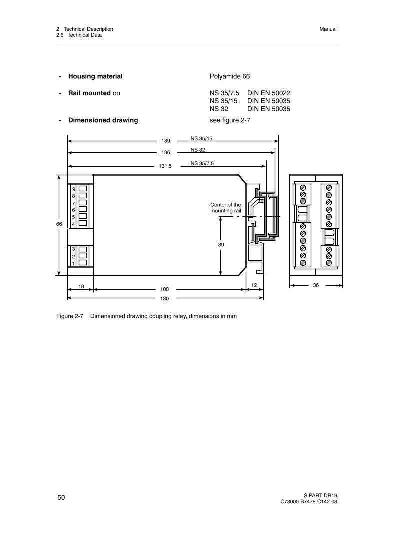
2 Technical Description2.6 Technical Data
Manual
50 SIPART DR19C73000-B7476-C142-08
- Housing material Polyamide 66
- Rail mounted on NS 35/7.5 DIN EN 50022NS 35/15 DIN EN 50035NS 32 DIN EN 50035
- Dimensioned drawing see figure 2-7
321
87
NS 35/15
Center of themounting rail
1218
9
139
136
100
130
36
131.5
39
66
NS 32
NS 35/7.5
654
Figure 2-7 Dimensioned drawing coupling relay, dimensions in mm
3 Functional description of the structure switches3.1 General
Manual
SIPART DR19C73000-B7476-C142-08
51
3 Functional description of the structure switches
3.1 General
The controller is adapted to the respective job by structure switches. The factory setting corre-sponds to the most usual setting of the individual functions so that only few structure switchesusually need to be set selectively during commissioning. However, it is recommendable tocompare the compatibility of the individual structure switch settings with the task in any case.
The structure switches S1 and S2 are fundamentally important. With S1 the controller type isset and thus the processing of command variable, main controlled variable and auxiliary con-trolled variables up to control difference generation determined. With S2 the controller outputstructure is set and thus the processing of the automatic manual, safety and tracking variablesas well as the manipulated variable output determined as a K- or S-output.
The functions of the structure switches S3 to S89 correspond to the logical order of signal pro-cessing. S90 and S91 describe the restart conditions, S92 to S99 the transmission procedure ofthe serial interface.
The structure switches are described in this order in the following description.
. NOTE
The control elements on the front are shown in Figure 1, page 5 and are indicatedin the text by numbers in brackets. The structure switches are designated by S**.
3.2 Analog input signal processing (S3 to S21)
see fig. 3-1, page 53
Each of the maximum 3 analog inputs is fed through an AD-converter which performs the 50 or60 Hz interference suppression (S3) by averaging over 20 or 16 2/3 ms. UNI input signals canbe applied at input AI1. With S5 the type of input signal is determined, S6 selects the thermo-couple type at the thermocouple input. The temperature unit is determined at PT100 and thethermocouple inputs with S7.
S8 and S9 are assigned to the module inputs AI2 and AI3 (e.g. current input 0/4 to 20 mA).With S9> 3 AI3 is structured for use of the UNI module. Analogously with input AI1, S10 deter-mines the type of input signal and S11 the thermocouple type for AI3.
At the same time S4, S8 and S9 decide whether operation is to take place with or withoutmeasuring range monitoring (transmitter fault). A separate AD-converter routine without averag-ing is responsible for monitoring so that the manual operation which is possible via S51 comesin to action as bumplessly as possible in the event of a transmitter fault. The monitor signalsdropping below -2.5 and exceeding +106.25 % per channel with a hysteresis of 0.25 % on thePV-X-digital display. By an OR link of all single messages the group transmitter fault MUF isformed which can be assigned to the digital outputs and negated optionally (see figure 3-2,page 56 and chapter 3.8, page 118). Only the analog inputs selected with the transmitter faultmonitor are monitored, displayed on the front panel (the appropriate position stays dark in thecase of analog inputs not selected with transmitter fault) and signaled with the OR link. The
3 Functional description of the structure switches3.2 Analog input signal processing (S3 to S21)
Manual
52 SIPART DR19C73000-B7476-C142-08
error message is acknowledged with the Shift key (12). The fault message signal via the ORlink is available until the selected analog inputs are back in the working range.
After measuring range monitoring the 3 analog inputs are each fed through a 1st order filter(parameter t1 to t3 can be set in the parameterization mode onPA). The factory setting is 1 s.
With S12 to S14 every channel can now be reduced optionally and a channel linearizedoptionally with S21. This enables even unlinear process variables to be represented physicallycorrectly (function and setting of the 13 vertex values, see chapter 3.10.4 (page126 ) and fig-ure 3-39, page 127).
The controllers-, manipulated- or disturbance variables to be processed for the controller types(S1) can be acquired with S15 to S20 from the 3 analog inputs.
The disturbance variable z is connected optionally via the D-element or the controller output(S48). yN serves as a tracking input for the manipulated variable in K-controllers (S2=0) orS-controllers with external feedback (S2=3) and yR as a manipulated variable feedback inS-controllers with internal feedback (S2=2) or as position feedback in S-controllers with externalfeedback (S2=3).
The controller or process variables are available for assignment to the analog output (S57) andthe limit value alarm (S83 to S87) and can be read by the SES. With this input structure mostcontrol tasks can be solved in connection with the different controller types and controller outputstructures.
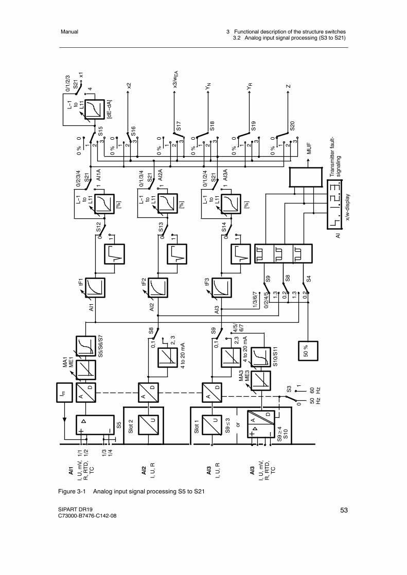
3 Functional description of the structure switches3.2 Analog input signal processing (S3 to S21)
Manual
SIPART DR19C73000-B7476-C142-08
53
50%
1/1
1/2
1/3
1/4
Slot2
I m A
D
MA1
ME1
Slot1 or
S9≥
4S10S9≤
3
S5
S5/S6/S7
U
A
D
A
D
A
D
U
AI1
I,U,m
V,R,R
TD,
TC
AI2
I,U,R
AI3
I,U,R
AI3
I,U,m
V,R,R
TD,
TC
MA3
ME3
4to20
mA
4to20
mA
S10/S11
S3
01
50 Hz
60 Hz
4/5/
6/7
2,3
2,3
S8
S9
0,1
0,1
AI2
AI1
AI3 1/
3/6/7
0/2/4/5
1.3
0.2
1.3
0.2
S8
S9
S4
tF3
tF2
tF1
AI
0 1
S14
0 1
S13
0 1
S12
L--1 to L11
L--1 to L11
L--1 to L11
[%]
[%]
[%]
0/2/3/4
1
S21
0/1/3/4
1
S21
0/1/2/4
1
S21AI2A
AI1A
AI3A
x/w-display
MUF
0%
0
0%
0
0%
0
0%
0
0%
0
0%
0
1 23
S15
1 23
S16
1 23
S17
1 23
S18
1 23
S19
1 23
S20
0/1/2/3
S21
x1
x24
[dE--dA]
x3/w
EA
YN
YR Z
Transm
itterfault-
signaling
L--1 to L11
Figure 3-1 Analog input signal processing S5 to S21
3 Functional description of the structure switches3.3 Digital input signal processing (S23 to S42)
Manual
54 SIPART DR19C73000-B7476-C142-08
3.3 Digital input signal processing (S23 to S42)
D Assignment and direction of action of the digital inputs (S23 to S42)
see figure 3-2, page 56
The control signals CB, He ...bLS, bLPS, PU are assigned by the structure switches S23 toS34 to the digital inputs DI1 to BE7 or the Low status. The High status is also possible whenassigning CB (S23) and P (S27). The control signals can also be negated optionally by thestructure switches S35 to S41.
The number of digital inputs (DI1 and DI2 already in the standard controller) can beextended for example by DI3 to DI7 with the options module 5BE (6DR2801--8C) in slot(S22 = 2).
When using the module 4DO 24 V + 2DI (6DR2801--8E) it is possible to extend by two (DI3,DI4) inputs (S22 = 1).
When using options modules in slot 3, structure switch S22 must be set according to theassignment, otherwise there will be an error message (see chapter 5.5, page 202).
All digital inputs can be read by the SES.
D Linking the digital inputs DI1 to DI7 with the control signals via the SES.(S42, S43, S52 and S93)
see figure 3-3, page 57
The control signal CB (S23) may be available either as a static signal or as a pulse (keyoperation by control desk) at the digital input (S42). Every positive edge trips the flip-flopwhen selecting the pulse input. In the following descriptions the output status of the flip-flopis assumed as CB.
All control signals (bLb as of software version --B6, tSH as of software version --B9) can alsobe specified by the SES at S93 = 2, 3, (4, 5)1) and Ored with the appropriate control signalsvia the digital inputs. Since the top operating hierarchy in a computer coupling should be inthe autarchic signal controller, the control signals can be switched off by the rounding withRC = Int∧CB via the internal/external key (13) of the controller or via CBES (with optionaltime monitor) or via CBDI (central computer fail line).
In addition the internal toggle stage can be addressed at S93 = 2 to 5 parallel to the keyactuation via IntES.
The CB-signal is formed at S93 = 2, (4)1) as OR-function from CBES via the serial interfaceand CBDI via the digital input so that operation is optionally possible with one signal.
1) as of software version –A7
3 Functional description of the structure switches3.3 Digital input signal processing (S23 to S42)
Manual
SIPART DR19C73000-B7476-C142-08
55
At S93 = 3, (5)1) the OR-function is replaced by an AND-function so that the CB set by theSES can be reset by a central computer fail line.
At the same time the sources for the external setpoint wES or wEA and for the trackingmanipulated variable yES or yN are switched over with S93. The depth of intervention isdetermined additionally by the serial interface. This makes it possible to specify the processvariables analogly for example and the corresponding status signals via the SES.
The function RC = Int∧CB (computer operation) also controls the manipulated variableswitching in the command variable switching in the controller types S1 = 0 to 4, i.e. also inSPC-operation (see chapter 3.4, page 59).
The two controller types S1 = 5/6 operate without command variable switching. The internalkey and the control signal CB are available with the link RC = Int∨ CB for locking operationthrough the serial interface (e. g. when linking to control systems).
At S42 = 0 static switching is performed by the logical function RC = Int∧CB. Whenpreset to Int (Internal LED (15) off) you can switch statically between the controller and con-troller values (command- and manipulatede variable) with CB. The computer standby CB isdisplayed negated by the C-LED (14) (C = CB, CB = 1≙ C LED off). The computer standbyof the controller is signaled negated as a message signal RB = Int. Computer operation RCis also signalled negated as a message signal RC = Int∧CB .
At S42 = 1 a static switching with acknowledgement takes place. Every time the computer isrecovered (CB from 0! 1) If the internal flip-flop is set to 1 (internal LED on, C LED off), sothat computer operation RC = Int∧CB only becomes effective after pressing the internal key(Int = 0).
With S43 = 0/2 the internal/external key can be deactivated and only internal or externaloperation selected.
The control signal H is generated as an OR-function by the manual/automatic key (9) withsubsequent flip-flop (Hi) and the control signal He whereby He can be preset by the SES orthe digital inputs in the way described above.
With the structure switch S52 the automatic/manual switching on the control front panel(S52 = 1 only automatic mode or S52 = 2 only manual mode) is blocked. It is still possible toswitch to manual operation by He in the “only automatic” position. The manual LED (12) al-ways indicates the active status (see also chapter 3.6, page 101).
At S52 = 0 to 2 He is switched statically both via the SES and the digital inputs At S52 = 3/4the connection takes place dynamically, i.e. every positive edge switches manual-automatic-manual. In addition, at structure switch S52 = 4 the locking of HeES with RC = Int∨CB isreleased.
1) as of software version --A5
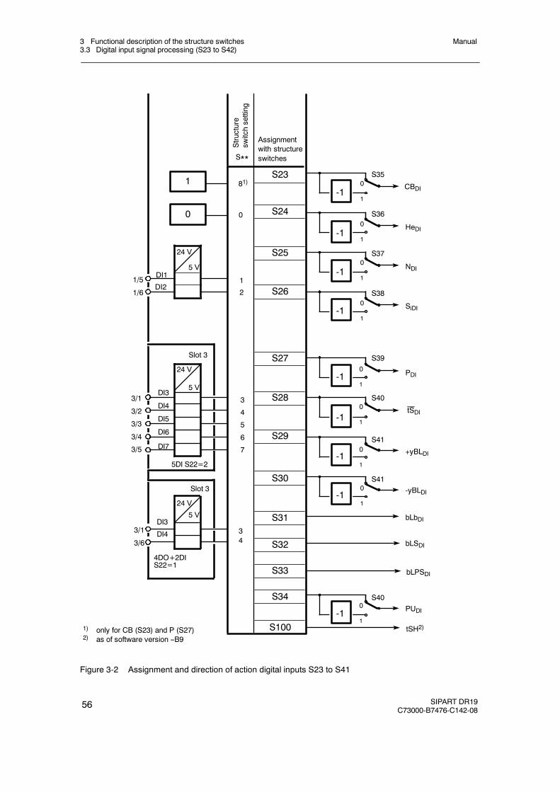
3 Functional description of the structure switches3.3 Digital input signal processing (S23 to S42)
Manual
56 SIPART DR19C73000-B7476-C142-08
3/1
3/2
3/3
3/4
3/5
1/5
1/6
3/1
3/6
DI1
DI3
DI4
DI5
DI6
DI7
DI3
DI4
Assignmentwith structureswitches
5DI S22=2
4DO+2DIS22=1
Slot 3
Slot 3
S**
S24
S25
S26
S27
S29
S30
S31
S32
S33
S23CBDI
SiDI
PDI
-yBLDI
+yBLDI
HeDI
NDI
0
1
1
0
1
S35
0
1
S36
0
1
S37
0
1
0
1
S39
0
1
S41
0
1
S41
S28
bLbDI
bLSDI
bLPSDI
1) only for CB (S23) and P (S27)2) as of software version --B9
tSDI
0
24 V
5 V
DI2
24 V
5 V
24 V
5 V
Structure
switchsetting
S34PUDI
0
1
S40
S38
S40
-1
-1
-1
-1
-1
-1
-1
-1
-1S100
81)
0
1
2
3
4
5
6
7
34
tSH2)
Figure 3-2 Assignment and direction of action digital inputs S23 to S41
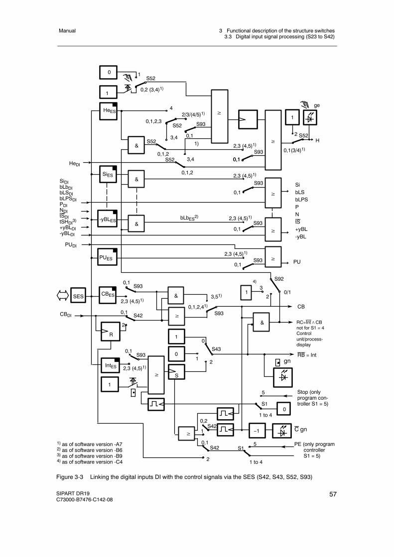
3 Functional description of the structure switches3.3 Digital input signal processing (S23 to S42)
Manual
SIPART DR19C73000-B7476-C142-08
57
0,2 (3,4)1)
S52
4
0,1
CBDI
C gn
gn
0,1,2,3S52
2/3/(4/5)1)
S523,4
0,1,2S52 3,4
0,1,2
2,3 (4,5)1)S93
0,1
0,1
2,3 (4,5)1)
0,1
S93
S42
3,51)
S93CB
2
S430,1
2,3 (4,5)1)
S93
0,2
S42
1
0 1
HeES
&
&
&
SiES
≥S52
ge
0,1(3/4)1)
2
1
-yBLES
≥
SibLSbLPSPNtS+yBL-yBL
0,1
0
1
≥
&
2,3 (4,5)1)
S93
0,1
≥
2,3 (4,5)1)S93
0,1
H
SES
SiDIbLbDIbLSDIbLPSDIPDINDItSDItSHDI3)+yBLDI-yBLDI
HeDI
CBES
RC=Int∧CBnot for S1 = 4Controlunit/process-display
&
≥
0,1,2,41)
1
1
0
S≥
RB = Int
--1
1) as of software version -A72) as of software version -B63) as of software version -B94) as of software version -C4
&
IntES
S93
2
PUDI
PUES ≥S930,1
2,3 (4,5)1)
PU
R
≥
2
0,1
1
S10
Stop (onlyprogram con-troller S1 = 5)
PE (only programcontrollerS1 = 5)
S15
1 to 4
5
1 to 4
S42
1)
bLbES2)
1
4)
3
20/1
S92
Figure 3-3 Linking the digital inputs DI with the control signals via the SES (S42, S43, S52, S93)
3 Functional description of the structure switches3.3 Digital input signal processing (S23 to S42)
Manual
58 SIPART DR19C73000-B7476-C142-08
D Functional explanation of the control signals
CB Computer-standbyThis digital signal together with the internal/external key causes switching in thesetpoint range. In SPC central Computer-Fail-line.
He Manual externalThis signal blocks the output of the controller and enables direct manualadjustment of the manipulated variable on the front control panel.
N TrackingWith this signal the output of the K-controller and the three-position steppercontroller with external position feedback is tracked to the tracking signal y N.
Si Safety operationIn K-controllers and three-position stepper controllers with external positionfeedback the manipulated variable approaches the parameterized safety value.In three-position stepper controllers with internal feedback the manipulated vari-able runs independently of the safety setting value to a defined limit position.
bLS Blocking structuringThe whole configuration is blocked with the exception of the onlineparameterization level.
bLPS Blocking of the parameterization and structuringThe entire configuring of the instrument is blocked, this means theparameterization as well. Only the normal process operation according to thepreselected controller type is permitted.
bLb Blocking operationThis signal blocks the entire front panel operation of the instrument.
P P-Operation controllerWith this signal the controller is switched to P-operation.
PU Setpoint/program switchingControl signal for connecting SHN in multiplpe setpoint mode (S1 = 1) orcontrol signal for switching the program from P1 to P2 (only program controller6DR1902/5, S1 = 5)
tS Setpoint rampWith this signal the set setpoint ramp time can be rendered ineffective(tS = High≙ ramp switched off). Reset at S1 = 5 (program controller,transmitter)
tSH Setpoint change (setpoint ramp)The setpoint change is stopped with this signal. The setpoint change continueswhen the signal is reset.
yBL Direction-dependent blocking of the manipulated variableDirection-dependent limiting of the manipulated variable by external signals,e.g. from the limit switches of the actuating drives. This limiting is effective inevery operating mode.
3 Functional description of the structure switches3.4 Controller type (S1, S43 to S46)
Manual
SIPART DR19C73000-B7476-C142-08
59
3.4 Controller type (S1, S43 to S46)
3.4.1 General, recurrent functions
D Manual setpoint preset wi or nominal ratio preset wvi on the control front panel.
The internal setpoint can always be adjusted with the keys (7), (8) when the green internal-LED (15) lights up and the setpoint is displayed by the switching key in the display (2). Thesignal lamp “w” then lights up. The adjusting facility is marked by↗ in the tables. Exceptionsto this rule are expressly mentioned in the individual controller types. The adjustment oper-ates incrementally, in the first step with a resolution of 1 digit and then an adjustment pro-gression so that major changes can also be performed quickly. After every interruption in theadjustment by releasing the keys, the progression starts again with the smallest adjustmentstep.
D Setpoint preset wi or nominal ratio preset wvi by the SES
Whenever the internal setpoint can be adjusted by the k.eys (7), (8), presetting is alsopossible parallel to this by the SES. Since the SES can only adjust absolutely and notincrementally, it is advisable to use the setpoint ramp tS to avoid steps.
In addition the control signal Int and the automatic-manual switching with the manualmanipulated variable adjustment can be set by the SES so that a complete parallel processoperation through the SES is possible (see also chapter 3.6, page 101).
D Source for the external setpoint (S93)
The external setpoint w E may come from two different sources depending on the controllertype.
external setpoint as absolute value via the analog inputs (wEA) S93 = 0, 1, (4, 5)1) andexternal setpoint as an absolute value via the SES (wES) S93 = 2, 3
D Setpoint ramp tS
With the parameter tS (oFPA), the adjustment speed of the active setpoint w (in the ratiocontroller S1 = 3 the active nominal ratio) can be set over 0 to 100 %. At tS = oFF theadjustment speed approaches1. With the control signal tS = 1 the set setpoint ramp isswitched off (the setpoint then changes suddenly).
With the setpoint ramp sudden setpoint steps to the untracked variables SH, wi, wES atS46 = 1 and wEA, can be avoided.
1) as of software version --A5
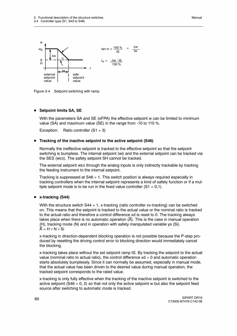
3 Functional description of the structure switches3.4 Controller type (S1, S43 to S46)
Manual
60 SIPART DR19C73000-B7476-C142-08
safesetpointvalue
externalsetpointvalue
wE
Δw
ttw
αSH
w
tw =
tan α = 100 %tS
Δwtw
Δw . tS100 %
=
Figure 3-4 Setpoint switching with ramp
D Setpoint limits SA, SE
With the parameters SA and SE (oFPA) the effective setpoint w can be limited to minimumvalue (SA) and maximum value (SE) in the range from -10 to 110 %.
Exception: Ratio controller (S1 = 3)
D Tracking of the inactive setpoint to the active setpoint (S46)
Normally the ineffective setpoint is tracked to the effective setpoint so that the setpointswitching is bumpless. The internal setpoint (wi) and the external setpoint can be tracked viathe SES (wES). The safety setpoint SH cannot be tracked.
The external setpoint wEA through the analog inputs is only indirectly trackable by trackingthe feeding instrument to the internal setpoint.
Tracking is suppressed at S46 = 1. This switch position is always required especially intracking controllers when the internal setpoint represents a kind of safety function or if a mul-tiple setpoint mode is to be run in the fixed value controller (S1 = 0,1).
D x-tracking (S44)
With the structure switch S44 = 1, x-tracking (ratio controller xv-tracking) can be switchedon. This means that the setpoint is tracked to the actual value or the nominal ratio is trackedto the actual ratio and therefore a control difference xd is reset to 0. The tracking alwaystakes place when there is no automatic operation (A). This is the case in manual operation(H), tracking mode (N) and in operation with safety manipulated variable ys (Si).A = H∨N∨Si
x-tracking in direction-dependent blocking operation is not possible because the P-step pro-duced by resetting the driving control error to blocking direction would immediately cancelthe blocking.
x-tracking takes place without the set setpoint ramp tS. By tracking the setpoint to the actualvalue (nominal ratio to actual ratio), the control difference xd = 0 and automatic operationstarts absolutely bumplessly. Since it can normally be assumed, especially in manual mode,that the actual value has been driven to the desired value during manual operation, thetracked setpoint corresponds to the rated value.
x-tracking is only fully effective when the tracking of the inactive setpoint is switched to theactive setpoint (S46 = 0, 2) so that not only the active setpoint w but also the setpoint feedsource after switching to automatic mode is tracked.
3 Functional description of the structure switches3.4 Controller type (S1, S43 to S46)
Manual
SIPART DR19C73000-B7476-C142-08
61
At S46 = 1 (without tracking) the control difference is 0 during the A-operation but the olduntracked setpoint becomes active again after switching to automatic mode. With thesetpoint ramp tS this step-shaped setpoint change takes place via a time ramp.
This combination is always useful when it is not guaranteed during A-operation (especially insafety mode) that the actual value will be driven to the desired rated value by the actuatingmanipulation and the tracking variable would not be correct in full x-tracking.
D Constants c1 to c7
Linking of the process variables with the constants is possible depending on the controllertype, whereby the constants c1 to c3 are used for the control variable links, the constants c4and c5 for the command variable links.
The constants are set in the parameterization mode onPA.
The constant c6 serves for proportioning the disturbance variable connection z to the con-troller output ya (see figure 3-9, page 71). It can be set in the parameterization mode onPA.
The constant c7 is used in P-controller operation as a factor for increasing the Kp-value.(P/PI-switchover, see figure 3-23, page 99).
D Control signals for the setpoint switching
If available in the individual controller types, the setpoint switching takes place depending onthe control signals Int (internal/external key) and CB (computer standby) as an AND-functionRC = Int∧CB and its negation. The status of the control signal CB and the internal key (13)is indicated by the C LED (14) and the internal LED (15).
In 5-setpoint operation (S1 = 1) the signal PU is used in an AND-operation in addition to theCB control signal to connect the values SHx.
With S43 the internal/external key (13) can be deactivated and blocked in the settings inter-nal or external (see figure 3-3, page 57). The factory setting is S42 = 0 (only internal).
With S23, the CB-signal can be set to Low or High or assigned to a digital input, (see fig-ure 3-2, page 56). The factory setting is S23 = 8, CB = High.
The setpoint switching can be varied freely with these structuring possibilities:
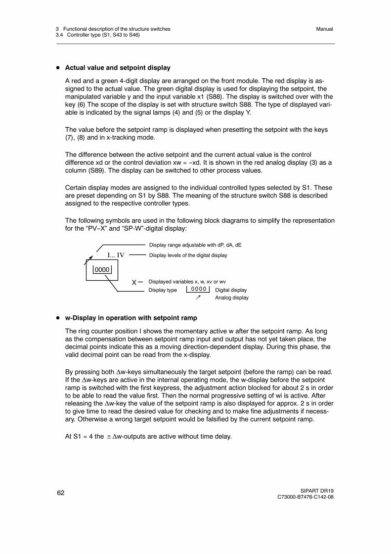
3 Functional description of the structure switches3.4 Controller type (S1, S43 to S46)
Manual
62 SIPART DR19C73000-B7476-C142-08
D Actual value and setpoint display
A red and a green 4-digit display are arranged on the front module. The red display is as-signed to the actual value. The green digital display is used for displaying the setpoint, themanipulated variable y and the input variable x1 (S88). The display is switched over with thekey (6) The scope of the display is set with structure switch S88. The type of displayed vari-able is indicated by the signal lamps (4) and (5) or the display Y.
The value before the setpoint ramp is displayed when presetting the setpoint with the keys(7), (8) and in x-tracking mode.
The difference between the active setpoint and the current actual value is the controldifference xd or the control deviation xw = --xd. It is shown in the red analog display (3) as acolumn (S89). The display can be switched to other process values.
Certain display modes are assigned to the individual controlled types selected by S1. Theseare preset depending on S1 by S88. The meaning of the structure switch S88 is describedassigned to the respective controller types.
The following symbols are used in the following block diagrams to simplify the representationfor the “PV--X” and “SP-W”-digital display:
Displayed variables x, w, xv or wv
Display type Digital display↗ Analog display
0000
I... IV
X0000
Display range adjustable with dP, dA, dE
Display levels of the digital display
D w-Display in operation with setpoint ramp
The ring counter position I shows the momentary active w after the setpoint ramp. As longas the compensation between setpoint ramp input and output has not yet taken place, thedecimal points indicate this as a moving direction-dependent display. During this phase, thevalid decimal point can be read from the x-display.
By pressing both Δw-keys simultaneously the target setpoint (before the ramp) can be read.If the Δw-keys are active in the internal operating mode, the w-display before the setpointramp is switched with the first keypress, the adjustment action blocked for about 2 s in orderto be able to read the value first. Then the normal progressive setting of wi is active. Afterreleasing the Δw-key the value of the setpoint ramp is also displayed for approx. 2 s in orderto give time to read the desired value for checking and to make fine adjustments if necess-ary. Otherwise a wrong target setpoint would be falsified by the current setpoint ramp.
At S1 = 4 the±Δw-outputs are active without time delay.
3 Functional description of the structure switches3.4 Controller type (S1, S43 to S46)
Manual
SIPART DR19C73000-B7476-C142-08
63
D Analog display
The red analog bar display can be assigned the control difference (or control error) orprocess variables (0 to 100 %) with the structure switch S89. The resolution of the controldifference display can be set with S89. Since this variable is represented as a column and isbipolar, the zero value is displayed separately with a green LED.
In the process variable display 1 or 2 marks/LEDs (caterpillar) light up alternately. Thedisplay has 20 light marks to 100 % which gives a resolution of 2.5 %.
D Display range
The display range for the x- and w-display is set together with the parameter dP (decimalpoint), dA (start value) and dE (end value) in the structuring mode oFPA.
With dA the numeric value to be displayed at calculated value 0 is set. With dE the numericvalue to be displayed at calculated value 1 is set. With dP the decimal point is set as a fixedpoint. If the start value is set less than the end value, an increasing display is given withincreasing arithmetic values and vice versa. The number range for the start and end valuesis -1999 to 9999, outside this range -oFL and oFL is displayed in overmodulation in theprocess operation level. The factory setting is 0.0 to 100.0 %.
With the refresh rate parameter dr (onPA) the digital displays can be settled down in thecase of restless process variables. Non-linear process variables can be represented physi-cally correctly by the linearization.
The display range set with dP, dA and dE is transferred depending on the controller type(S1) to the parameters and setpoints which can be assigned to the displayed variable:
With the appropriate assignment, this also applies for the limit value alarms A1 to A4, seechapter 3.10.3, page 125.
y-display
The manipulated variable is displayed by the 4-digit green digital display “SP-W” (2). Thevalue display has 3 digits. The first digit has a “y” for identification. The setting value is se-lected at Pos. II of the display using the Shift key or appears in manual mode (key (9) auto-matically (see also chapter 3.6, page 101).
When using as a process display (S1 = 4) the manipulated variable can also be shown inPos. II in 4 digits (y-identification is not applicable).
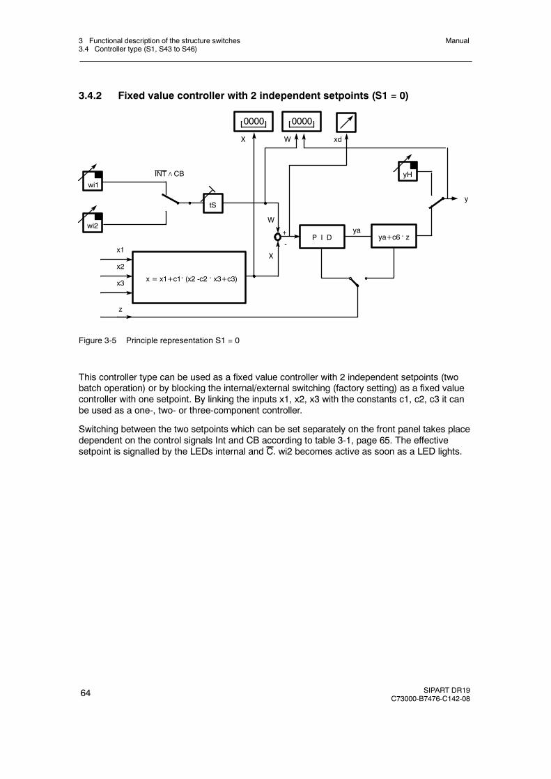
3 Functional description of the structure switches3.4 Controller type (S1, S43 to S46)
Manual
64 SIPART DR19C73000-B7476-C142-08
3.4.2 Fixed value controller with 2 independent setpoints (S1 = 0)
yaW
z
x3
x1
x2
ya+c6 . zP I D
W
+
-
wi2
wi1INT∧CB
x = x1+c1. (x2 -c2 . x3+c3)
X
0000
tS
yH
y
X
0000
xd
Figure 3-5 Principle representation S1 = 0
This controller type can be used as a fixed value controller with 2 independent setpoints (twobatch operation) or by blocking the internal/external switching (factory setting) as a fixed valuecontroller with one setpoint. By linking the inputs x1, x2, x3 with the constants c1, c2, c3 it canbe used as a one-, two- or three-component controller.
Switching between the two setpoints which can be set separately on the front panel takes placedependent on the control signals Int and CB according to table 3-1, page 65. The effectivesetpoint is signalled by the LEDs internal and C. wi2 becomes active as soon as a LED lights.
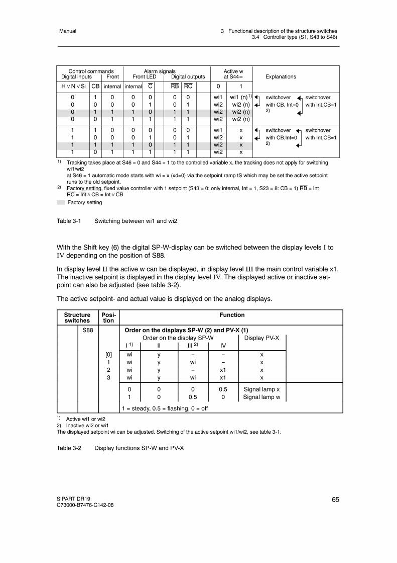
3 Functional description of the structure switches3.4 Controller type (S1, S43 to S46)
Manual
SIPART DR19C73000-B7476-C142-08
65
Control commands Alarm signals Active wDigital inputs Front Front LED Digital outputs at S44= Explanations
H∨N∨Si CB internal internal C RB RC 0 1
0 1 0 0 0 0 0 wi1 wi1 (n)1) switchover switchover0 0 0 0 1 0 1 wi2 wi2 (n) with CB, Int=0 with Int,CB=10 1 1 1 0 1 1 wi2 wi2 (n) 2)
0 0 1 1 1 1 1 wi2 wi2 (n)
1 1 0 0 0 0 0 wi1 x switchover switchover1 0 0 0 1 0 1 wi2 x with CB,Int=0 with Int,CB=11 1 1 1 0 1 1 wi2 x 2)
1 0 1 1 1 1 1 wi2 x1) Tracking takes place at S46 = 0 and S44 = 1 to the controlled variable x, the tracking does not apply for switching
wi1/wi2at S46 = 1 automatic mode starts with wi = x (xd=0) via the setpoint ramp tS which may be set the active setpointruns to the old setpoint.
2) Factory setting, fixed value controller with 1 setpoint (S43 = 0: only internal, Int = 1, S23 = 8: CB = 1) RB = IntRC = Int∧CB = Int∨CBFactory setting
Table 3-1 Switching between wi1 and wi2
With the Shift key (6) the digital SP-W-display can be switched between the display levels I toIV depending on the position of S88.
In display level II the active w can be displayed, in display level III the main control variable x1.The inactive setpoint is displayed in the display level IV. The displayed active or inactive set-point can also be adjusted (see table 3-2).
The active setpoint- and actual value is displayed on the analog displays.
Structureswitches
Posi-tion
Function
S88 Order on the displays SP-W (2) and PV-X (1)Order on the display SP-W Display PV-X
I 1) II III 2) IV[0] wi y -- -- x1 wi y wi -- x2 wi y -- x1 x3 wi y wi x1 x
0 0 0 0.5 Signal lamp x1 0 0.5 0 Signal lamp w
1 = steady, 0.5 = flashing, 0 = off1) Active wi1 or wi22) Inactive wi2 or wi1The displayed setpoint wi can be adjusted. Switching of the active setpoint wi1/wi2, see table 3-1.
Table 3-2 Display functions SP-W and PV-X
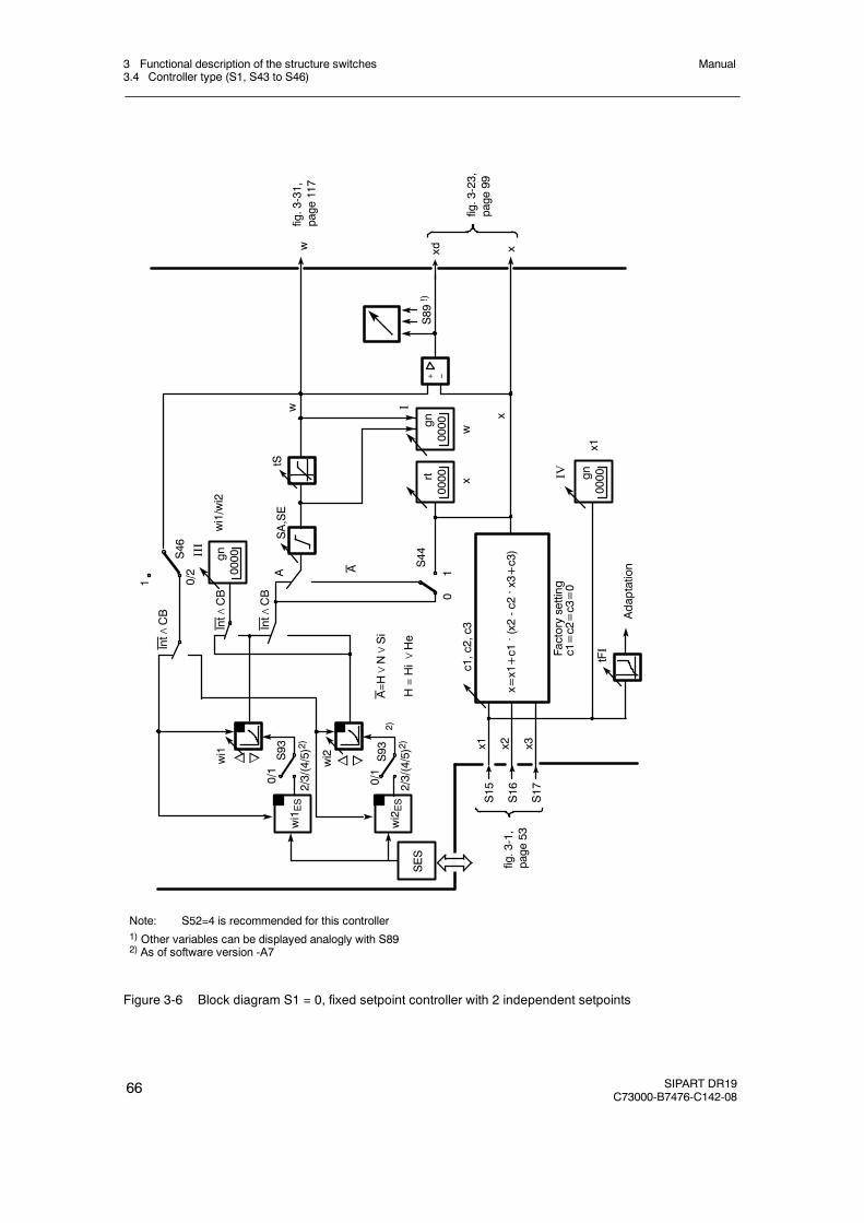
3 Functional description of the structure switches3.4 Controller type (S1, S43 to S46)
Manual
66 SIPART DR19C73000-B7476-C142-08
0/2S46
Int∧CB
xd
S93
2/3/(4/5)2)
0/1
0
c1,c2,c3
x
x
w
w
S15
S16
S17
Factorysetting
c1=c2=c3=0
x=x1+c1. (x2-c2. x3+c3)
x2x1 x3
tFΙ
tSSA,SE
wi1
n o
1
S44
Adaptation
SES
wi1ES
Int∧CB
Int∧CB
AA
x1
x
A=H∨N∨Si
III
0000
H=Hi∨
He
IV
0000
+ --
wi1/wi2
S93
2/3/(4/5)2)
0/1
wi2
wi2ES
n o
wfig.3-31,
page
117
Note: S52=4 is recommended for this controller1) Other variables can be displayed analogly with S892) As of software version -A7
fig.3-1,
page
53
fig.3-23,
page
99
1
gn
gn
2)
0000rt
0000gn
S89!)
I
Figure 3-6 Block diagram S1 = 0, fixed setpoint controller with 2 independent setpoints
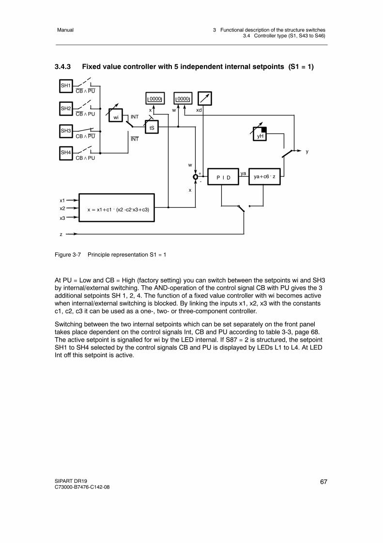
3 Functional description of the structure switches3.4 Controller type (S1, S43 to S46)
Manual
SIPART DR19C73000-B7476-C142-08
67
3.4.3 Fixed value controller with 5 independent internal setpoints (S1 = 1)
ya
w
x3
x1x2
ya+c6 . zP I D+
-
x = x1+c1 . (x2 -c2.x3+c3)
x
y
yHtS
wi
0000 0000
wx xd
INT
INT
CB∧PUSH4
CB∧PUSH3
CB∧PUSH2
CB∧PUSH1
z
Figure 3-7 Principle representation S1 = 1
At PU = Low and CB = High (factory setting) you can switch between the setpoints wi and SH3by internal/external switching. The AND-operation of the control signal CB with PU gives the 3additional setpoints SH 1, 2, 4. The function of a fixed value controller with wi becomes activewhen internal/external switching is blocked. By linking the inputs x1, x2, x3 with the constantsc1, c2, c3 it can be used as a one-, two- or three-component controller.
Switching between the two internal setpoints which can be set separately on the front paneltakes place dependent on the control signals Int, CB and PU according to table 3-3, page 68.The active setpoint is signalled for wi by the LED internal. If S87 = 2 is structured, the setpointSH1 to SH4 selected by the control signals CB and PU is displayed by LEDs L1 to L4. At LEDInt off this setpoint is active.
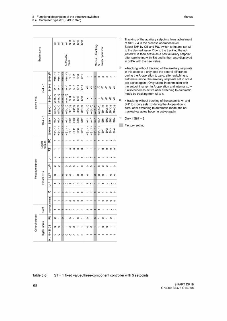
3 Functional description of the structure switches3.4 Controller type (S1, S43 to S46)
Manual
68 SIPART DR19C73000-B7476-C142-08
S46=0
S46=1
S46=2
1)S46=0
S46=1
S46=2
1)
00
01
11
10
00
11
00
11
11
01
00
11
01
01
10
00
10
11
01
11
10
00
01
11
00
00
01
10
00
01
00
10
01
01
00
01
01
00
00
00
10
00
01
10
00
00
01
00
10
01
11
10
00
11
10
11
11
01
00
11
11
01
10
00
10
11
11
11
10
00
01
11
10
00
01
10
00
01
10
10
01
01
00
01
11
00
00
00
10
00
11
10
00
00
01
00
H∨N∨SiCB
PU
InternalInternal
CL1
4)L2
4)L3
4)L4
4)RB
RC
wi(n,↗
)wi↗
wi(n,↗
)wi(n,↗
)wi↗
wi(n,↗
)wi(n,↗
)wi↗
wi(n,↗
)wi(n,↗
)wi↗
wi(n,↗
)wi(n,↗
)wi↗
wi(n,↗
)wi(n,↗
)wi↗
wi(n,↗
)wi(n,↗
)wi↗
wi(n,↗
)wi(n,↗
)wi↗
wi(n,↗
)SH1
SH1
SH1(n)
SH1
SH1
SH1
SH2
SH2
SH2(n)
SH2
SH2
SH2
SH3
SH3
SH3(n)
SH3
SH3
SH3
SH4
SH4
SH4(n)
SH4
SH4
SH4
wi(n,↗
)wi↗
wi(n,↗
)x
x3)
xwi(n,↗
)wi↗
wi(n,↗
)x
x3)
xwi(n,↗
)wi↗
wi(n,↗
)x
x3)
xwi(n,↗
)wi↗
wi(n,↗
)x
x3)
xSH1
SH1
SH1(n)
x2)
x3)
xSH2
SH2
SH2(n)
x2)
x3)
xSH3
SH3
SH3(n)
x2)
x3)
xSH4
SH4
SH4(n)
x2)
x3)
x
Explanations
Digitalinputs
Front
FrontLE
Ds
Digital
outputs
S44
=0
S44
=1
Controlsignals
Message
signals
activewat
Autom
atic-
mode
wi
wi
wi
wi
SH1
SH2
SH3
SH4
Manual-,Tracking-
or safetyoperation
1) Tracking of the auxiliary setpoints llows adjustmentof SH1 = 4 in the process operation level.Select SH* by CB and PU, switch to Int and set wito the desired value. Due to the tracking the ad-justed wi is then active as a new auxiliary setpointafter sqwitching with Ext and is then also displayedin onPA with the new value.
2) x-tracking without tracking of the auxiliary setpointsin this case to x only sets the control differenceduring the A-operation to zero, after switching toautomatic mode, the auxiliary setpoints set in onPAare active again! (Only useful in connection withthe setpoint ramp). In A-operation and internal xd =0 also becomes active after switching to automaticmode by tracking from wi to x.
3) x-tracking without tracking of the setpoints wi andSH* to x only sets xd during the A-operation tozero, after switching to automatic mode, the un-tracked variables become active again!
4) Only if S87 = 2
Factory setting
Table 3-3 S1 = 1 fixed value-/three-component controller with 5 setpoints
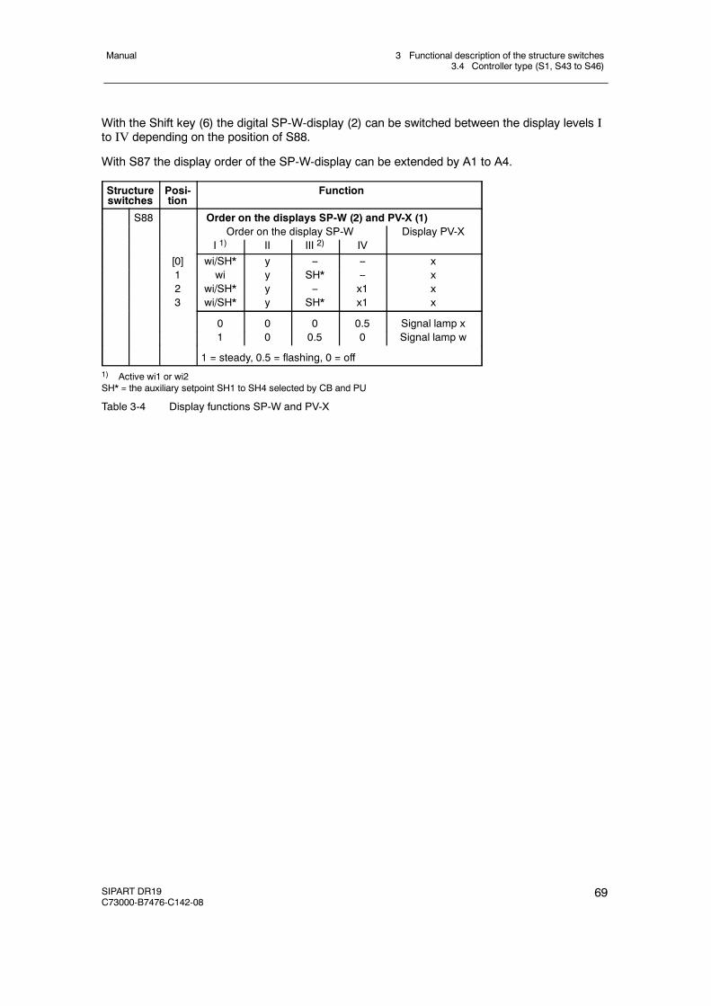
3 Functional description of the structure switches3.4 Controller type (S1, S43 to S46)
Manual
SIPART DR19C73000-B7476-C142-08
69
With the Shift key (6) the digital SP-W-display (2) can be switched between the display levels Ito IV depending on the position of S88.
With S87 the display order of the SP-W-display can be extended by A1 to A4.
Structureswitches
Posi-tion
Function
S88 Order on the displays SP-W (2) and PV-X (1)Order on the display SP-W Display PV-X
I 1) II III 2) IV[0] wi/SH* y -- -- x1 wi y SH* -- x2 wi/SH* y -- x1 x3 wi/SH* y SH* x1 x
0 0 0 0.5 Signal lamp x1 0 0.5 0 Signal lamp w
1 = steady, 0.5 = flashing, 0 = off1) Active wi1 or wi2SH* = the auxiliary setpoint SH1 to SH4 selected by CB and PU
Table 3-4 Display functions SP-W and PV-X
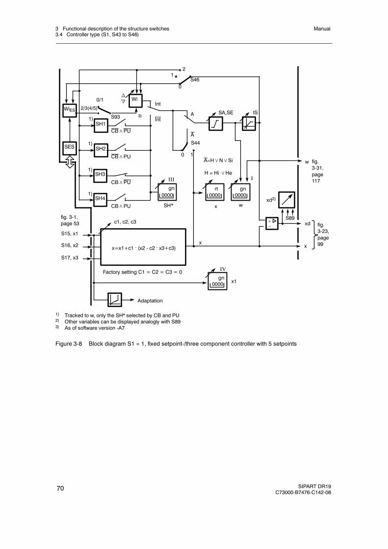
3 Functional description of the structure switches3.4 Controller type (S1, S43 to S46)
Manual
70 SIPART DR19C73000-B7476-C142-08
0
c1, c2, c3
1
S16, x2
S15, x1
S17, x3
no
Factory setting C1 = C2 = C3 = 0
Wi
SH4
SH3
SH2
SH1
21
0S46
1)
1)
1)
1)
SES
WiESS93
2/3(4/5)
0/1
Adaptation
x1
IV
0000gn
fig. 3-1,page 53
I
00000000gnrt
x w
A=H∨N∨Si
H = Hi∨He
A
A tSSA,SE
S44
Int
III
0000
SH*
3)
CB∧PU
CB∧PU
CB∧PU
CB∧PU
gn
+-- xd
x
w fig.3-31,page117
fig.3-23,page99
x=x1+c1 . (x2 - c2 . x3+c3)x
S89
xd2)
Int
1) Tracked to w, only the SH* selected by CB and PU2) Other variables can be displayed analogly with S893) As of software version -A7
Figure 3-8 Block diagram S1 = 1, fixed setpoint-/three component controller with 5 setpoints
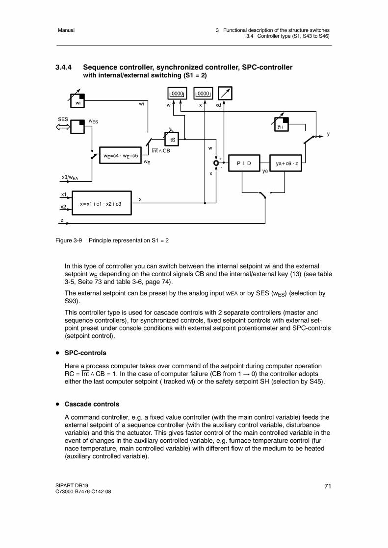
3 Functional description of the structure switches3.4 Controller type (S1, S43 to S46)
Manual
SIPART DR19C73000-B7476-C142-08
71
3.4.4 Sequence controller, synchronized controller, SPC-controllerwith internal/external switching (S1 = 2)
SES
wE=c4 · wE+c5wE
wi
wES
x3/wEAya
w
x
P I D ya+c6 · z
z
x1
x=x1+c1 · x2+c3x
x2
tSy
yH
wi
Int∧CB
0000 0000
w x xd
+
-
Figure 3-9 Principle representation S1 = 2
In this type of controller you can switch between the internal setpoint wi and the externalsetpoint wE depending on the control signals CB and the internal/external key (13) (see table3-5, Seite 73 and table 3-6, page 74).
The external setpoint can be preset by the analog input wEA or by SES (wES) (selection byS93).
This controller type is used for cascade controls with 2 separate controllers (master andsequence controllers), for synchronized controls, fixed setpoint controls with external set-point preset under console conditions with external setpoint potentiometer and SPC-controls(setpoint control).
D SPC-controls
Here a process computer takes over command of the setpoint during computer operationRC = Int∧CB = 1. In the case of computer failure (CB from 1! 0) the controller adoptseither the last computer setpoint ( tracked wi) or the safety setpoint SH (selection by S45).
D Cascade controls
A command controller, e.g. a fixed value controller (with the main control variable) feeds theexternal setpoint of a sequence controller (with the auxiliary control variable, disturbancevariable) and this the actuator. This gives faster control of the main controlled variable in theevent of changes in the auxiliary controlled variable, e.g. furnace temperature control (fur-nace temperature, main controlled variable) with different flow of the medium to be heated(auxiliary controlled variable).
3 Functional description of the structure switches3.4 Controller type (S1, S43 to S46)
Manual
72 SIPART DR19C73000-B7476-C142-08
D Synchronized controls
A command controller feeds several synchronized controllers simultaneously whose individ-ual setpoints can be set in a ratio to each other by the constants c4 and c5 and then dragthe controlled variables accordingly (controlled variable synchronization).
D Control signals for the setpoint switching
The setpoint switching takes place via the logic link RC = Int∧CB and its negation (seetable 3-5, page 73 and table 3-6, page 74). Both control signals can be set in addition totheir normal function as Shift key or control signal with the states 1 and 0 statically to 1 or 0(Int via S43, CB via S23), see figure 3-2, page 56 and figure 3-3, page 57.
The factory setting is Int = 1 (S43 = 0) and CB=1 (S23 = 8), so that in the factory settingthe internal setpoint wi is always active and cannot be switched!
This setting possibility enables you to perform the switching only dependent on Int (S43=2,S23=8) or only dependent on CB (S43=1, S23=1 to 7) as a sequence controller with internal/external switching. If the switching possibility is blocked in external position (S43=1, S23=8),the controller operates as a sequence controller without internal/external switching.
D Display of the external setpoint wE
With the Shift key (6) you can switch in display level III from digital SP-W-display to the ex-ternal setpoint wE and in display level IV to the main controlled variable x1. The active set-point is displayed in display levelI (S88). The active actual value is displayed on the digitalPV-X-display.
The x/w LEDs signal the display level.
D Operation with 2 or 3 setpoints
If the tracking of the inactive setpoint to the active setpoint has been suppressed withS46 = 1, a multiple setpoint operation is achieved (switching between wi, wE and SH (seetable 3-5, page 73 and table 3-6, page 74).
D Controlled variable processing
A 2-component control is implemented (disturbance variable connection). With factors c1and c3 the main controlled variable x1 can connect the auxiliary controlled variable x2 withweighting.
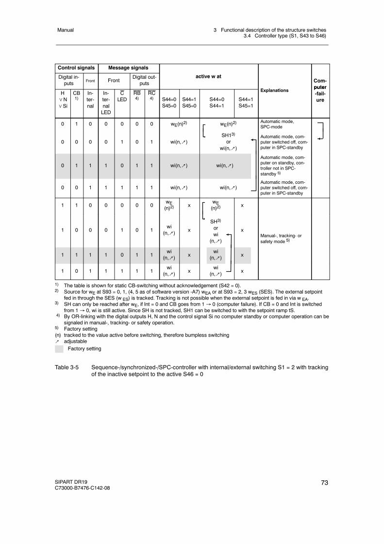
3 Functional description of the structure switches3.4 Controller type (S1, S43 to S46)
Manual
SIPART DR19C73000-B7476-C142-08
73
Control signals Message signals
Digital in-puts Front Front
Digital out-puts
active w at
E l ti
Com-puter
H∨N∨Si
CB1)
In-ter-nal
In-ter-nalLED
CLED
RB4)
RC4) S44=0
S45=0S44=1S45=0
S44=0S44=1
S44=1S45=1
Explanationsputer-fail-ure
0 1 0 0 0 0 0 wE(n)2) wE(n)2)Automatic mode,SPC-mode
0 0 0 0 1 0 1 wi(n,↗)SH13)
orwi(n,↗)
Automatic mode, com-puter switched off, com-puter in SPC-standby
0 1 1 1 0 1 1 wi(n,↗) wi(n,↗)
Automatic mode, com-puter on standby, con-troller not in SPC-standby 5)
0 0 1 1 1 1 1 wi(n,↗) wi(n,↗)Automatic mode, com-puter switched off, com-puter in SPC-standby
1 1 0 0 0 0 0wE(n)2) x
wE(n)2) x
1 0 0 0 1 0 1wi
(n,↗) x
SH3)
orwi
(n,↗)
xManual-, tracking- orsafety mode 5)
1 1 1 1 0 1 1wi
(n,↗) xwi
(n,↗) x
1 0 1 1 1 1 1wi
(n,↗) xwi
(n,↗) x
1) The table is shown for static CB-switching without acknowledgement (S42 = 0).2) Source for wE at S93 = 0, 1, (4, 5 as of software version -A7) wEA or at S93 = 2, 3 wES (SES). The external setpoint
fed in through the SES (w ES) is tracked. Tracking is not possible when the external setpoint is fed in via w EA.3) SH can only be reached after wE, if Int = 0 and CB goes from 1→ 0 (computer failure). If CB = 0 and Int is switched
from 1→ 0, wi is still active. Since SH is not tracked, SH1 can be switched to with the setpoint ramp tS.4) By OR-linking with the digital outputs H, N and the control signal Si no computer standby or computer operation can be
signaled in manual-, tracking- or safety operation.5) Factory setting(n) tracked to the value active before switching, therefore bumpless switching↗ adjustable
Factory setting
Table 3-5 Sequence-/synchronized-/SPC-controller with internal/external switching S1 = 2 with trackingof the inactive setpoint to the active S46 = 0
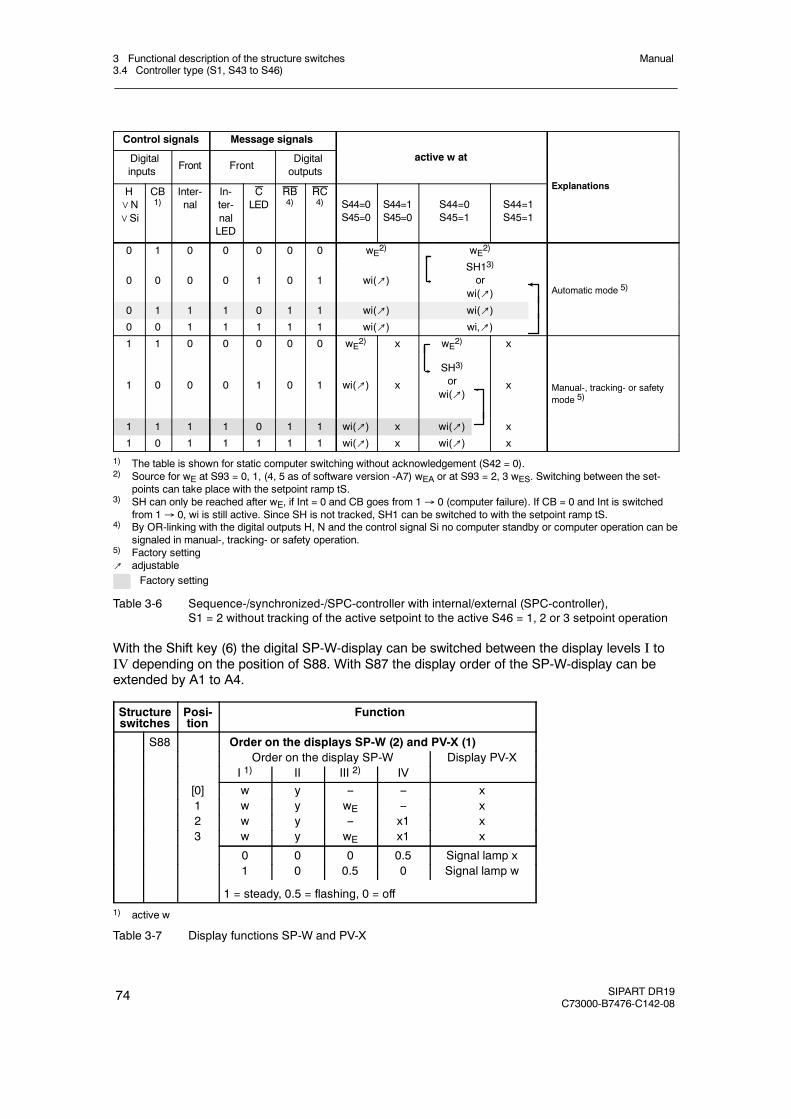
3 Functional description of the structure switches3.4 Controller type (S1, S43 to S46)
Manual
74 SIPART DR19C73000-B7476-C142-08
Control signals Message signals
Digitalinputs Front Front
Digitaloutputs
active w at
E l tiH∨N∨Si
CB1)
Inter-nal
In-ter-nalLED
CLED
RB4)
RC4) S44=0
S45=0S44=1S45=0
S44=0S45=1
S44=1S45=1
Explanations
0 1 0 0 0 0 0 wE2) wE2)
0 0 0 0 1 0 1 wi(↗)SH13)
orwi(↗) Automatic mode 5)
0 1 1 1 0 1 1 wi(↗) wi(↗)0 0 1 1 1 1 1 wi(↗) wi,↗)1 1 0 0 0 0 0 wE2) x wE2) x
1 0 0 0 1 0 1 wi(↗) x
SH3)
orwi(↗)
x Manual-, tracking- or safetymode 5)
1 1 1 1 0 1 1 wi(↗) x wi(↗) x
1 0 1 1 1 1 1 wi(↗) x wi(↗) x
1) The table is shown for static computer switching without acknowledgement (S42 = 0).2) Source for wE at S93 = 0, 1, (4, 5 as of software version -A7) wEA or at S93 = 2, 3 wES. Switching between the set-
points can take place with the setpoint ramp tS.3) SH can only be reached after wE, if Int = 0 and CB goes from 1→ 0 (computer failure). If CB = 0 and Int is switched
from 1→ 0, wi is still active. Since SH is not tracked, SH1 can be switched to with the setpoint ramp tS.4) By OR-linking with the digital outputs H, N and the control signal Si no computer standby or computer operation can be
signaled in manual-, tracking- or safety operation.5) Factory setting↗ adjustable
Factory setting
Table 3-6 Sequence-/synchronized-/SPC-controller with internal/external (SPC-controller),S1 = 2 without tracking of the active setpoint to the active S46 = 1, 2 or 3 setpoint operation
With the Shift key (6) the digital SP-W-display can be switched between the display levels I toIV depending on the position of S88. With S87 the display order of the SP-W-display can beextended by A1 to A4.
Structureswitches
Posi-tion
Function
S88 Order on the displays SP-W (2) and PV-X (1)Order on the display SP-W Display PV-X
I 1) II III 2) IV[0] w y -- -- x1 w y wE -- x2 w y -- x1 x3 w y wE x1 x
0 0 0 0.5 Signal lamp x1 0 0.5 0 Signal lamp w
1 = steady, 0.5 = flashing, 0 = off1) active w
Table 3-7 Display functions SP-W and PV-X
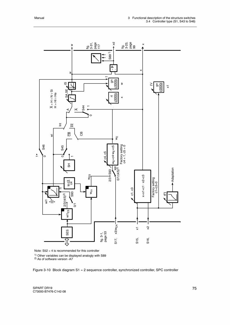
3 Functional description of the structure switches3.4 Controller type (S1, S43 to S46)
Manual
SIPART DR19C73000-B7476-C142-08
75
Factorysetting
c1=c3=0
S93
wES
xxdwe
A
0
2/3
1
11
0
0
CB
CB
AIntInt
wi
w
c1,c3
tFI
x1 x2
x3/w
EA
S44
S46
S45
Adaptation
x=x1+c1·x2+c3
wES
w-c3
c4SH w
E=c4·wE+c5
wE
c4,c5
Factorysetting
c4=1,c5
=0
n owi1
S93
wi1ES
SES
2/3/(4/5)2)
0/1
S17,
S15,
S16,
w
0/1/(4/5)2)
A=H∨N∨Si
H=Hi∨
He
Note: S52 = 4 is recommended for this controller1) Other variables can be displayed analogly with S892) As of software version -A7
fig.3-1,
page
53
2)
xw
+ --0000rt
0000gn
I
tSSA,SE
x
0000gnIV
S89!)
x1
fig.
3-31,
page
117
fig.
3-23,
page
99
Figure 3-10 Block diagram S1 = 2 sequence controller, synchronized controller, SPC controller

3 Functional description of the structure switches3.4 Controller type (S1, S43 to S46)
Manual
76 SIPART DR19C73000-B7476-C142-08
3.4.5 Controlled ratio controller (S1 = 3)
wVES
xv
xdwv
x2
wv
x1
x2
wVEA
vis=x1 - c5x2 ya
w
+
-x
P I D ya+c6 . z
y
yH
z
w=v . x2+c5
wvi
SES
v = vA to vEv = wv.(vE - vA)+vA
xv
Int∧CB
0000 0000
Figure 3-11 Principle representation S1 = 3
In a ration control the commanding process variable x2 is weighted with the adjustable ratio fac-tor and a basic value c5 added if necessary. The result forms the setpoint w for the followingcontrolled process variable x1.
w = v · x2 + c5
With xd = w - x1 the result is xd = v · x2 + c5 - x1
In the controlled state (xd = 0) the result is v = x1 - c5x2
, i.e. in the controlled state and atc5 = 0 x1
x2behaves according to the set ratio factor v.
A typical application are combustion rules where a fuel volume x1 beongs to every air volumex2 to guarantee optimum combustion.
The ratio factor range v = vA to vE is determined with the parameters vA and vE in the structur-ing mode oFPA in the range from 0.0 to 9.999 (factory setting vA = 0, vE = 1). In addition abasic value c5 (parameterization mode onPA) can be connected in the range from -1.999 to9.999 (factory setting = 0.0).
The standardized nominal ratio wv (wvi or wvE) in the range from 0 to 1 is converted to the ratiofactor range.
v = wv (vE - vA) + vA
With w = v · x2 + c5 w = [wv (vE - vA) + vA] x2 + c5 is given
With the Shift key (6) the digital SP-W-display can be switched between the display levels I toIV depending on the position of S88.
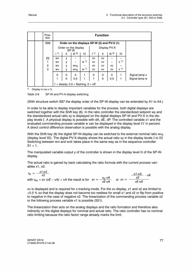
3 Functional description of the structure switches3.4 Controller type (S1, S43 to S46)
Manual
SIPART DR19C73000-B7476-C142-08
77
Posi-tion
Function
S88 Order on the displays SP-W (2) and PV-X (1)
Order on the displaySP-W
Display PV-X
I 1) II III 2) IV I 1) II III 2) IV[0] wv y -- -- xv xv -- --1 wv y -- w 1) xv xv -- x 1)
2 wv y wvE -- xv xv xv --3 wv y wvE w 1) xv xv xv x 1)
0 0 0 1 0 0 0 1 Signal lamp x1 0 0.5 1 1 0 0.5 1 Signal lamp w
1 = steady, 0.5 = flashing, 0 = off1) Display in xxx.x %
Table 3-8 SP-W and PV-X-display switching
(With structure switch S87 the display order of the SP-W-display can be extended by A1 to A4.)
In order to be able to display important variables for the process, both digital displays areswitched together with the Shift key (6). In the ratio controller the standardized setpoint wy andthe standardized actual ratio xy is displayed on the digital displays SP-W and PV-X in the dis-play levels I. A physical display is possible with dA, dE, dP. The controlled variable x1 and theevaluated commanding process variable w can be displayed in the display level IV in percent.A direct control difference observation is possible with the analog display.
With the Shift key (6) the digital SP-W-display can be switched to the external nominal ratio wvE(display level III). The digital PV-X-display shows the actual ratio xy in the display levels I to IIISwitching between wvi and wvE takes place in the same way as in the sequence controllerS1 = 1.
The manipulated variable output y of the controller is shown in the display level II of the SP-W-display.
The actual ratio is gained by back calculating the ratio formula with the current process vari-ables x1, x2:
vis = x1-c5x2
with vist = xv (vE -- vA) + vA the result is for xv = vis-vAvE-vA or xv = vE-vA
x1-c5x2
- vA
xv is displayed and is required for x-tracking-mode. For the xv-display, x1 and x2 are limited to+0.5 % so that the display does not become too restless for small x1 and x2 or flip from positiveto negative in the case of negative x2. The linearization of the commanding process variable x2or the following process variable x1 is possible (S21).
The linearization then acts on the analog displays and the ratio formation and therefore alsoindirectly on the digital displays for nominal and actual ratio. The ratio controller has no nominalratio limiting because the ratio factor range already marks the limit.
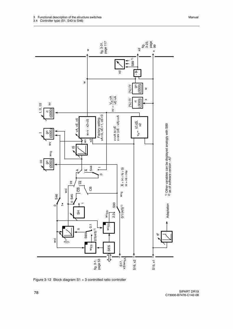
3 Functional description of the structure switches3.4 Controller type (S1, S43 to S46)
Manual
78 SIPART DR19C73000-B7476-C142-08
CB
wvi
0
AA
1
10
0
wV
Adaptation
CB
S93
w
xv=
tF
x2S44
S46
S45
Int
wv
Factorysetting
vA=0,vE=1,c5=0
SH
vA,vE,c5
tS
III
I
w=v
·x2+c5
v is=x1-c5
x2
v=vA
tovE
v=wv(vE-vA)+vA
xd x
2,3
Vis-vA
vE-vA
1
w
S17,
x3/wv E
A
S16,x2
S15,x1
1)Othervariables
canbe
displayedanaloglywith
S89
2)as
ofsoftw
areversion--A
7
SES
n owvi
0/1/(4/5)1)
wVES
wi ES
S93
0,1
2/3(4/5)1)2)
wVES
A=H∨N∨Si
H=Hi∨
He
0000
0000
wVE
wVE
fig.3-1,
page
53
Int
gngn
I,II,III
0000rt
xw
+ --0000rt
0000gn
[%]IV
S891)
[%]IV
xd
xv
fig.3-31,
page
117
fig.
3-23,
page
99
Figure 3-12 Block diagram S1 = 3 controlled ratio controller
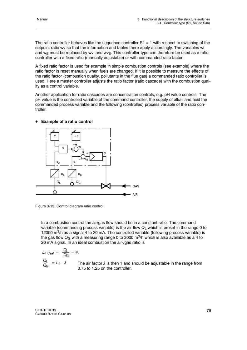
3 Functional description of the structure switches3.4 Controller type (S1, S43 to S46)
Manual
SIPART DR19C73000-B7476-C142-08
79
The ratio controller behaves like the sequence controller S1 = 1 with respect to switching of thesetpoint ratio wv so that the information and tables there apply accordingly. The variables wiand wE must be replaced by wvi and wvE. This controller type can therefore be used as a ratiocontroller with a fixed ratio (manually adjustable) or with commanded ratio factor.
A fixed ratio factor is used for example in simple combustion controls (see example) where theratio factor is reset manually when fuels are changed. If it is possible to measure the effects ofthe ratio factor (combustion quality, pollutants in the flue gas) a commanded ratio controller isused. Here a master controller adjusts the ratio factor (ratio cascade) with the combustion qual-ity as a control variable.
Another application for ratio cascades are concentration controls, e.g. pH value controls. ThepH value is the controlled variable of the command controller, the supply of alkali and acid thecommanded process variable and the following (controlled) process variable of the ratio con-troller.
D Example of a ratio control
+
+
x1
GASQGQL
KGKL
x2
v
xy
xd- -
w
c
+
AIR
Figure 3-13 Control diagram ratio control
In a combustion control the air/gas flow should be in a constant ratio. The commandvariable (commanding process variable) is the air flow QL which is preset in the range 0 to12000 m3/h as a signal 4 to 20 mA. The controlled variable (following process variable) isthe gas flow QG with a measuring range 0 to 3000 m3/h which is also available as a 4 to20 mA signal. In an ideal combustion the air-/gas ratio is
L ideal = = 4.QLQG
= L ⋅ λQLQG The air factor λ is then 1 and should be adjustable in the range from
0.75 to 1.25 on the controller.
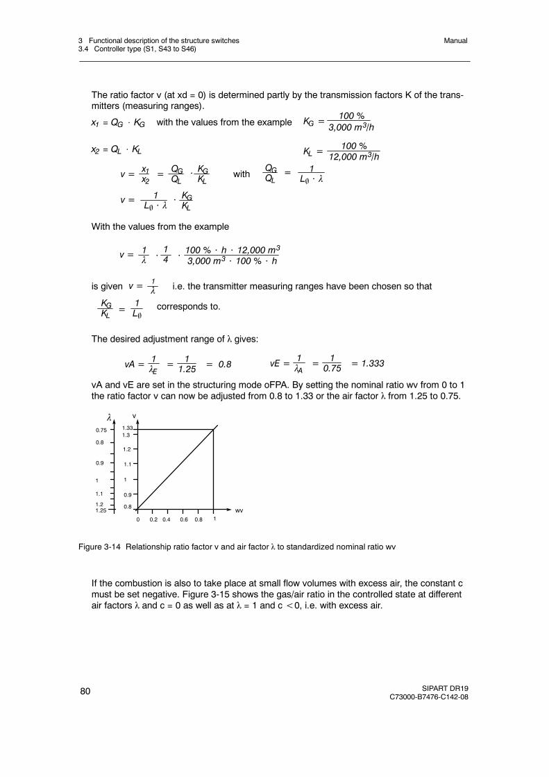
3 Functional description of the structure switches3.4 Controller type (S1, S43 to S46)
Manual
80 SIPART DR19C73000-B7476-C142-08
The ratio factor v (at xd = 0) is determined partly by the transmission factors K of the trans-mitters (measuring ranges).
x1 = QG ⋅ KG with the values from the example100 %
3,000 m3/hKG =
x2 = QL ⋅ KL 100 %12,000 m3/hKL =
v = = QGQL
x1x2
⋅ withQGQL
1L ⋅ λ
=
v = 1L ⋅ λ
KGKL
KGKL
⋅
With the values from the example
v = 1λ ⋅
14
100 % ⋅ h ⋅ 12,000 m33,000 m3 ⋅ 100 % ⋅ h⋅
is given v = 1λ i.e. the transmitter measuring ranges have been chosen so that
KGKL =
1L
corresponds to.
The desired adjustment range of λ gives:
vA = =1λE
11.25 = 0.8 vE = =1
λA10.75 = 1.333
vA and vE are set in the structuring mode oFPA. By setting the nominal ratio wv from 0 to 1the ratio factor v can now be adjusted from 0.8 to 1.33 or the air factor λ from 1.25 to 0.75.
0.75
1.21.25
0.8
0.9
1
1.1
1.2
0.2 0.6
1.331.3
10.80.40
0.8
1.1
0.9
1
wv
vλ
Figure 3-14 Relationship ratio factor v and air factor λ to standardized nominal ratio wv
If the combustion is also to take place at small flow volumes with excess air, the constant cmust be set negative. Figure 3-15 shows the gas/air ratio in the controlled state at differentair factors λ and c = 0 as well as at λ = 1 and c<0, i.e. with excess air.
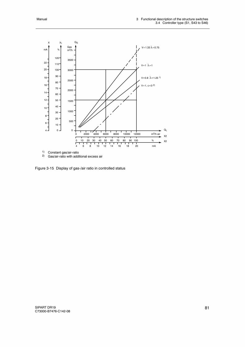
3 Functional description of the structure switches3.4 Controller type (S1, S43 to S46)
Manual
SIPART DR19C73000-B7476-C142-08
81
1) Constant gas/air-ratio2) Gas/air-ratio with additional excess air
%mAGasm3/h
V=1.33 λ=0.75
0 2000 4000 6000 8000 10000 12000 m3/h air
QL
V=1 λ=1
V=0.8 λ=1.25 1)
V=1, c<0 2)
X2
4 6 8 10 12 14 16 18 20 mA
X2
0 10 20 30 40 50 60 70 80 90 100 %
22
20
18
16
14
12
10
8
6
4
120
110
100
90
80
70
60
50
40
30
20
10
0
3500
3000
2500
2000
1500
1000
500
X X1 QG
0
Figure 3-15 Display of gas-/air ratio in controlled status
3 Functional description of the structure switches3.4 Controller type (S1, S43 to S46)
Manual
82 SIPART DR19C73000-B7476-C142-08
3.4.6 Control unit/process display (S1 = 4)
The following functions are possible in this configuration: Process display and control unit.The configuration is identical for both applications. The input wiring for both is illustrated infigure 3-16.
D Process display, two-channel digital display(S93 = 0/1 and S43 = 1) see figure 3-16, page 83A process variable is assigned to the green SP-W-digital display by wEA and the other vari-able to the red PV-X-digital display by x1. S88 = 2 must be configured to ensure both vari-ables are displayed. The variables are displayed as physical values. If you want the valuedisplayed in % instead of the physical display, the variable is assigned at S88 = 3 to the SP-W-display through the yR-input.
The physical display is determined for both displays together with the offline parameters dP,dA, dE.
The linearizer (S21) which can be assigned to an analog input has a direct effect on thedisplay.
The control difference xd is displayed in factory setting on the red analog display, othervariables can be displayed with S89.
D Process display, single-channel digital display and displayed limit valuessee fig. 3-16, page 83
In the structure switch position S88 = 4, the green SP-W-display is dark. It is useful here tocall the limit values [%] additionally in the display with the Shift key, e.g. via S87 = 3 to 6.The limit value no. and exceeding of the limit value are indicated by LEDs (17).
The display in the red PV-X-display is fed through the x2 input. The change in the character-istic which is possible by linearization is also displayed here.
The control difference xd is displayed in factory setting on the red analog display, othervariables can be displayed with S89.
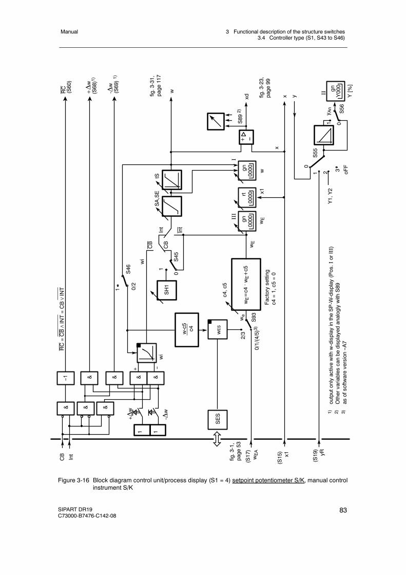
3 Functional description of the structure switches3.4 Controller type (S1, S43 to S46)
Manual
SIPART DR19C73000-B7476-C142-08
83
(S17)
wEA
(S19)
yR
wSH1
w-c5
c4
xd
+ --
0/2
1
S46
wES
SES
2/3
c4,c5
wE=c4. wE+c5
SA,SE
tS
(S15)
x1
RC(S60)
+Δw
(S68)1)
-Δw
(S69)1)
x
1 0S56
0
1 2 3 oFF
Y1,Y2
x
Int
Int
CB
CB
S45
1
0/1/(4/5)3)S93we
Factorysetting
c4=1,c5
=0
S55
RC=CB∧INT=CB∨INT
CB
Int
1 1
-Δw
+ Δw
wi
wi
y An
1)outputonlyactivewith
w-display
intheSP-W
-display
(Pos.I
orIII)
2)Othervariables
canbe
displayedanaloglywith
S89
3)as
ofsoftw
areversion--A
7
+
& &
& & & &
fig.3-1,
page
53
0000gnIII
wE
0000rt
x1
0000 wgn
IS892)
y Y000gnII
0
Y[%]
wE
fig.3-31,
page
117
fig.3-23,
page
99
&--1
--
Figure 3-16 Block diagram control unit/process display (S1 = 4) setpoint potentiometer S/K, manual controlinstrument S/K
3 Functional description of the structure switches3.4 Controller type (S1, S43 to S46)
Manual
84 SIPART DR19C73000-B7476-C142-08
D Control units
The integrated control unit function always includes a setpoint potentiometer and a manualcontrol instrument in the following versions:
-- trackable K-setpoint potentiometer-- S-setpoint potentiometer-- trackable K-manual control instrument (S2 = 0)-- S-two-position control unit with 2 outputs (heating/cooling) (S2 = 1)-- S-three-position manual control unit internal feedback (S2 = 2)-- S-three-position manual control unit external feedback (S2 = 3)
The ability to combine setpoint potentiometer and manual control instrument type dependson the application. Either the setpoint potentiometer or the manual control instrument canuse the K-output, the remaining function must have an S-output.
- Setpoint potentiometersee fig. 3-16, page 83
S- and K-setpoint potentiometers are installed parallel. In the S-setpoint potentiometerthe switching outputs±Δw can be locked depending on the internal key (13) and thecontrol signal CB, the status message is indicated by the signal lamps Int and C, seetable 3-9, page 85. The setpoint adjusted incrementally by the switching outputs is fedback via the w-display (input wEA, switching is blocked in position Ext, S43 = 1).
In the K setpoint potentiometer the tracking of the internal setpoint is controlled depend-ent on the internal key (13) and the control signal CB, see table 3-9. The tracking variableis fed in via w EA. The active setpoint is output by the assignment of w to the analog out-put AO (S57 = 2/3).
It is also possible to display the actual value as in the normal controller.
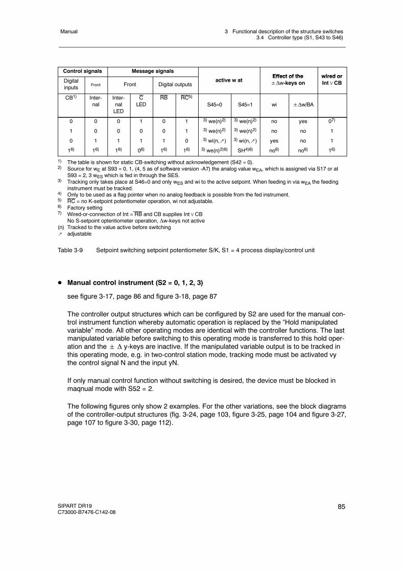
3 Functional description of the structure switches3.4 Controller type (S1, S43 to S46)
Manual
SIPART DR19C73000-B7476-C142-08
85
Control signals Message signalsEffect of the wired or
Digitalinputs Front Front Digital outputs
active w atEffect of the±Δw-keys on
wired orInt∨CB
CB1) Inter-nal
Inter-nalLED
CLED
RB RC5)
S45=0 S45=1 wi ±Δw/BA
0 0 0 1 0 1 3) we(n)2) 3) we(n)2) no yes 07)
1 0 0 0 0 1 3) we(n)2) 3) we(n)2) no no 1
0 1 1 1 1 0 3) wi(n,↗) 3) wi(n,↗) yes no 1
16) 16) 16) 06) 16) 16) 3) we(n)2)6) SH4)6) no6) no6) 16)
1) The table is shown for static CB-switching without acknowledgement (S42 = 0).2) Source for wE at S93 = 0, 1, (4, 5 as of software version -A7) the analog value wEA, which is assigned via S17 or at
S93 = 2, 3 wES which is fed in through the SES.3) Tracking only takes place at S46=0 and only wES and wi to the active setpoint. When feeding in via wEA the feeding
instrument must be tracked.4) Only to be used as a flag pointer when no analog feedback is possible from the fed instrument.5) RC = no K-setpoint potentiometer operation, wi not adjustable.6) Factory setting7) Wired-or-connection of Int = RB and CB supplies Int∨CB
No S-setpoint optentiometer operation, Δw-keys not active(n) Tracked to the value active before switching↗ adjustable
Table 3-9 Setpoint switching setpoint potentiometer S/K, S1 = 4 process display/control unit
D Manual control instrument (S2 = 0, 1, 2, 3)
see figure 3-17, page 86 and figure 3-18, page 87
The controller output structures which can be configured by S2 are used for the manual con-trol instrument function whereby automatic operation is replaced by the “Hold manipulatedvariable” mode. All other operating modes are identical with the controller functions. The lastmanipulated variable before switching to this operating mode is transferred to this hold oper-ation and the Δ y-keys are inactive. If the manipulated variable output is to be tracked inthis operating mode, e.g. in two-control station mode, tracking mode must be activated vythe control signal N and the input yN.
If only manual control function without switching is desired, the device must be blocked inmaqnual mode with S52 = 2.
The following figures only show 2 examples. For the other variations, see the block diagramsof the controller-output structures (fig. 3-24, page 103, figure 3-25, page 104 and figure 3-27,page 107 to figure 3-30, page 112).
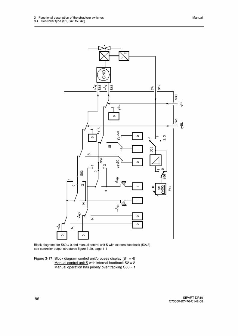
3 Functional description of the structure switches3.4 Controller type (S1, S43 to S46)
Manual
86 SIPART DR19C73000-B7476-C142-08
-Δy
y R0 1
+Δy
02,3
S55
1
S56
0 2S52
1
H
0
2S52
1
H
+Δy H
-Δy H
NSi
Si
y S>50
+yBL
-yBL
+yBL
-yBL
N+Δy
- Δy A
S19
S58
S58
S29
S30
αE
yGND
y S<50
y An
0 0
00
11
01
0
0
0
Y000gnII
Block diagrams for S50 = 0 and manual control unit S with external feedback (S2=3)see controller output structures figure 3-29, page 111
Figure 3-17 Block diagram control unit/process display (S1 = 4)Manual control unit S with internal feedback S2 = 2Manual operation has priority over tracking S50 = 1
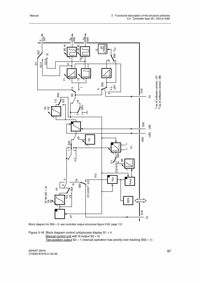
3 Functional description of the structure switches3.4 Controller type (S1, S43 to S46)
Manual
SIPART DR19C73000-B7476-C142-08
87
S52
S55
21
S93
Y1 Y2N
+yBL
-yBL
oFF
2/3
0
2
0/1/(4/5)1)
1
1
0
0
0
S56
S53
N
Si
yn
A
ya
tP,tM(S2=0)
YA YE
YS
y S57
-Δy
S58
<>
S54
1/30/2
YA
YE
30 1
S2
tM,tA
tP,tE
+ Δy
S58
1/3
0/2
S54
S18
S29
S30
S19
YAn
H
0/1 tM
2/3/(4/5)1)S93
1)as
ofsoftw
areversion--A
72)as
ofsoftw
areversion--B
6
1
y R
y H
y N
y ESy E
S
y E
y HES
SES
12/13
10/11
0/1
S57
Y1
Y2
Y000gn
II
2)
Block diagram for S50 = 0, see controller output structures figure 3-30, page 112
Figure 3-18 Block diagram control unit/process display S1 = 4Manual control unit with K-output S2 = 0/Two-position output S2 = 1 (manual operation has priority over tracking S50 = 1)
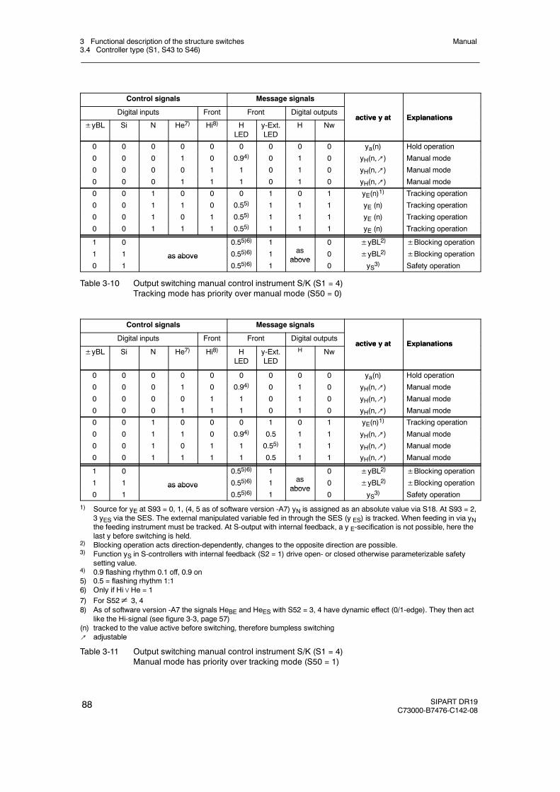
3 Functional description of the structure switches3.4 Controller type (S1, S43 to S46)
Manual
88 SIPART DR19C73000-B7476-C142-08
Control signals Message signals
Digital inputs Front Front Digital outputsactive y at Explanations
±yBL Si N He7) Hi8) HLED
y-Ext.LED
H Nwactive y at Explanations
0 0 0 0 0 0 0 0 0 ya(n) Hold operation
0 0 0 1 0 0.94) 0 1 0 yH(n,↗) Manual mode
0 0 0 0 1 1 0 1 0 yH(n,↗) Manual mode
0 0 0 1 1 1 0 1 0 yH(n,↗) Manual mode
0 0 1 0 0 0 1 0 1 yE(n)1) Tracking operation
0 0 1 1 0 0.55) 1 1 1 yE (n) Tracking operation
0 0 1 0 1 0.55) 1 1 1 yE (n) Tracking operation
0 0 1 1 1 0.55) 1 1 1 yE (n) Tracking operation
1 0 0.55)6) 1 0 ±yBL2) ±Blocking operation1 1 as above 0.55)6) 1 as
above0 ±yBL2) ±Blocking operation
0 1as above
0.55)6) 1above
0 yS3) Safety operation
Table 3-10 Output switching manual control instrument S/K (S1 = 4)Tracking mode has priority over manual mode (S50 = 0)
Control signals Message signals
Digital inputs Front Front Digital outputsactive y at Explanations
±yBL Si N He7) Hi8) HLED
y-Ext.LED
H Nwactive y at Explanations
0 0 0 0 0 0 0 0 0 ya(n) Hold operation
0 0 0 1 0 0.94) 0 1 0 yH(n,↗) Manual mode
0 0 0 0 1 1 0 1 0 yH(n,↗) Manual mode
0 0 0 1 1 1 0 1 0 yH(n,↗) Manual mode
0 0 1 0 0 0 1 0 1 yE(n)1) Tracking operation
0 0 1 1 0 0.94) 0.5 1 1 yH(n,↗) Manual mode
0 0 1 0 1 1 0.55) 1 1 yH(n,↗) Manual mode
0 0 1 1 1 1 0.5 1 1 yH(n,↗) Manual mode
1 0 0.55)6) 1 0 ±yBL2) ±Blocking operation1 1 as above 0.55)6) 1 as
above0 ±yBL2) ±Blocking operation
0 1as above
0.55)6) 1above
0 yS3) Safety operation
1) Source for yE at S93 = 0, 1, (4, 5 as of software version -A7) yN is assigned as an absolute value via S18. At S93 = 2,3 yES via the SES. The external manipulated variable fed in through the SES (y ES) is tracked. When feeding in via yNthe feeding instrument must be tracked. At S-output with internal feedback, a y E-secification is not possible, here thelast y before switching is held.
2) Blocking operation acts direction-dependently, changes to the opposite direction are possible.3) Function yS in S-controllers with internal feedback (S2 = 1) drive open- or closed otherwise parameterizable safety
setting value.4) 0.9 flashing rhythm 0.1 off, 0.9 on5) 0.5 = flashing rhythm 1:16) Only if Hi∨He = 17) For S52≠ 3, 48) As of software version -A7 the signals HeBE and HeES with S52 = 3, 4 have dynamic effect (0/1-edge). They then act
like the Hi-signal (see figure 3-3, page 57)(n) tracked to the value active before switching, therefore bumpless switching↗ adjustable
Table 3-11 Output switching manual control instrument S/K (S1 = 4)Manual mode has priority over tracking mode (S50 = 1)
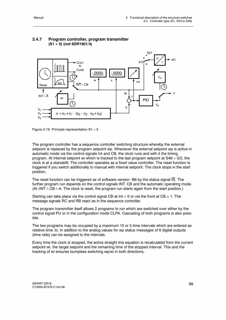
3 Functional description of the structure switches3.4 Controller type (S1, S43 to S46)
Manual
SIPART DR19C73000-B7476-C142-08
89
3.4.7 Program controller, program transmitter(S1 = 5) (not 6DR1901/4)
0000
wi
x =x1+c1 . (x2 - c2 . x3+c3)
PID
YH
Y
YA
xw
W+
-XX1
X2X3
xd
0000
S57
AO2/3CLb1
toCLb6
wpReset INT∧CB
INT∧A
UI
Figure 3-19 Principle representation S1 = 5
The program controller has a sequence controller switching structure whereby the externalsetpoint is replaced by the program setpoint wp. Whenever the external setpoint wp is active inautomatic mode via the control signals Int and CB, the clock runs and with it the timingprogram. At internal setpoint wi which is tracked to the last program setpoint at S46 = 0/2, theclock is at a standstill. The controller operates as a fixed value controller. The reset function istriggered if you switch additionally to manual with internal setpoint. The clock stops in the startposition.
The reset function can be triggered as of software version -B6 by the status signal tS. Thefurther program run depends on the control signals INT, CB and the automatic operating mode.(At /INT∧CB∧A: The clock is reset, the program run starts again from the start position.)
Starting can take place via the control signal CB at Int = 0 or via the front at CB = 1. Themessage signals RC and RB react as in the sequence controller.
The program transmitter itself allows 2 programs to run which are switched over either by thecontrol signal PU or in the configuration mode CLPA. Cascading of both programs is also poss-ible.
The two programs may be occupied by a maximum 10 or 5 time intervals which are entered asrelative time Δt. In addition to the analog values for wp status messages of 6 digital outputs(time rails) can be assigned to the intervals.
Every time the clock is stopped, the active straight line equation is recalculated from the currentsetpoint wi, the target setpoint and the remaining time of the stopped interval. This and thetracking of wi ensures bumpless switching wp/wi in both directions.
3 Functional description of the structure switches3.4 Controller type (S1, S43 to S46)
Manual
90 SIPART DR19C73000-B7476-C142-08
D Operating modes at the end of the program
At the end of the last interval at the end of the program the controller is automaticallyswitches to wi and operates as a fixed value controller in automatic operation.If operation takes place via S42 = 0, 1 with static CB, this switching tykes place by settingthe Int flip-flop stage to 1.
If operation takes place via S42 = 2 with dynamic CB, the switching takes place by a reset ofthe CB flip-flop stage to 0. The restart then takes place by pressing the Int key or an edge atcontrol input CB.
Due to the tracking of wi the entered value at the end of the last interval is active atS46 = 0/2 in the program pause. At S45 = 1 the internal setpoint is tracked to the safetysetpoint SH1 so that free cooling functions can also be implemented.
An end of program message is also possible by the status message of a digital output CLb1to CLb6.
D Program transmitter
If you assign the current output Iy to the active w, operation as a program transmitter whichcan then feed several sequence controllers for example.
D Cyclic program run
The cyclic program run is possible in the following operating modes:
- With external connection: Start/Stop function external or through device front
In dynamic CB (S42 = 2), assignment of a digital output CLbx (S70 to 75) with the statusmessage “end of program” (x.PE.x, in CLPA) and external connection of the binary outputwith the binary input CB, the program run is started again by the positive edge at the endof the program.
The cyclic program run can be ended by interrupting the external connection. By switch-ing setpoint internal/external (internal key 13), the start/stop function is given through thedevice front.
- Device-internal Start/Stop-function only via device front
At CB = High (S23 = 8) and CB-setting dynamic (S42 = 2), the cyclic program run ispossible without an external connection.
The start/stop function takes place through the device front by internal/external switching(internal key 13). The free DI or DO can be used for other functions.
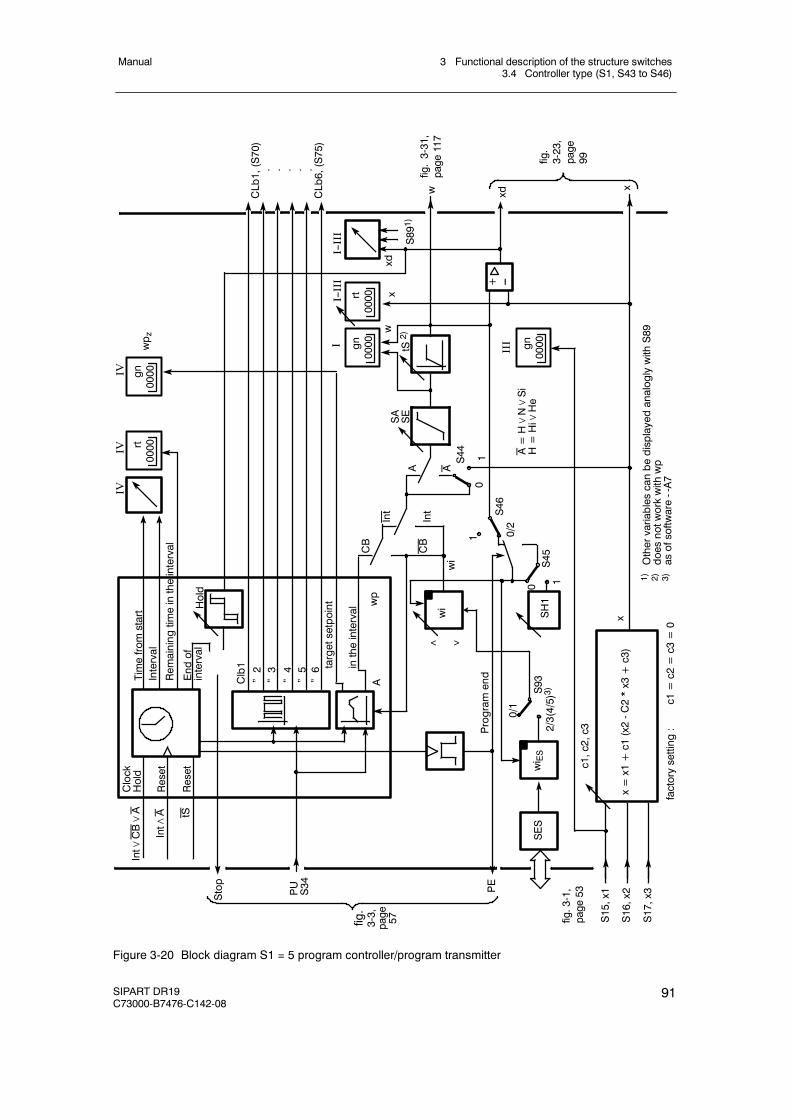
3 Functional description of the structure switches3.4 Controller type (S1, S43 to S46)
Manual
SIPART DR19C73000-B7476-C142-08
91
wi
SH1
SASE
x=x1+c1(x2-C2*x3+c3)
Clock
Hold
Reset
Stop
PUS34 PE
S15,x1
S16,x2
S17,x3
c1,c2,c3
x
Timefromstart
Interval
Remainingtimeintheinterval
Endof
interval
Hold
Clb1
”2”3”4”5”6 targetsetpoint
intheinterval
Awp
CB
Int
A
01S44
tS2)
S891)
CLb1,(S70)
. . . . .CLb6,(S75)
w xd
x
IV
Programend
wi
1 0/2S46
0 1S45
1)OthervariablescanbedisplayedanaloglywithS89
2)doesnotworkwithwp
3)asofsoftware--A7
factorysetting:
c1=c2=c3=0
xdx
w
SES
wi ES
0/1
2/3(4/5)3)S93
Reset
tS
Int∧
A
Int∨
CB∨A
A
0000gnI
0000rtI--III +
0000gn
Int
CB
< >
A=H∨N∨Si
H=Hi∨He
III
0000rt
0000gn
IVIV
wp z
fig.3-1,
page
53
fig.
3-3,
page 57
fig.3-31,
page
117
fig.
3-23,
page
99
--
I--III
Figure 3-20 Block diagram S1 = 5 program controller/program transmitter
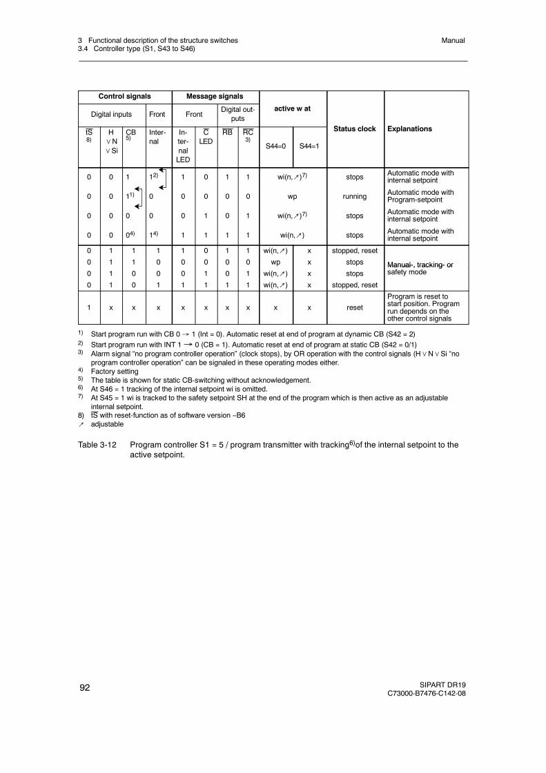
3 Functional description of the structure switches3.4 Controller type (S1, S43 to S46)
Manual
92 SIPART DR19C73000-B7476-C142-08
Control signals Message signals
Digital inputs Front FrontDigital out-
putsactive w at
St t l k E l titS8)
H∨N∨Si
CB5)
Inter-nal
In-ter-nalLED
CLED
RB RC3)
S44=0 S44=1
Status clock Explanations
0 0 1 12) 1 0 1 1 wi(n,↗)7) stops Automatic mode withinternal setpoint
0 0 11) 0 0 0 0 0 wp running Automatic mode withProgram-setpoint
0 0 0 0 0 1 0 1 wi(n,↗)7) stops Automatic mode withinternal setpoint
0 0 04) 14) 1 1 1 1 wi(n,↗) stops Automatic mode withinternal setpoint
0 1 1 1 1 0 1 1 wi(n,↗) x stopped, reset
0 1 1 0 0 0 0 0 wp x stops Manual-, tracking- or0 1 0 0 0 1 0 1 wi(n,↗) x stops
Manual-, tracking- orsafety mode
0 1 0 1 1 1 1 1 wi(n,↗) x stopped, reset
1 x x x x x x x x x reset
Program is reset tostart position. Programrun depends on theother control signals
1) Start program run with CB 0 1 (Int = 0). Automatic reset at end of program at dynamic CB (S42 = 2)2) Start program run with INT 1 0 (CB = 1). Automatic reset at end of program at static CB (S42 = 0/1)3) Alarm signal “no program controller operation” (clock stops), by OR operation with the control signals (H∨N∨Si “no
program controller operation” can be signaled in these operating modes either.4) Factory setting5) The table is shown for static CB-switching without acknowledgement.6) At S46 = 1 tracking of the internal setpoint wi is omitted.7) At S45 = 1 wi is tracked to the safety setpoint SH at the end of the program which is then active as an adjustable
internal setpoint.8) tS with reset-function as of software version --B6↗ adjustable
Table 3-12 Program controller S1 = 5 / program transmitter with tracking6)of the internal setpoint to theactive setpoint.
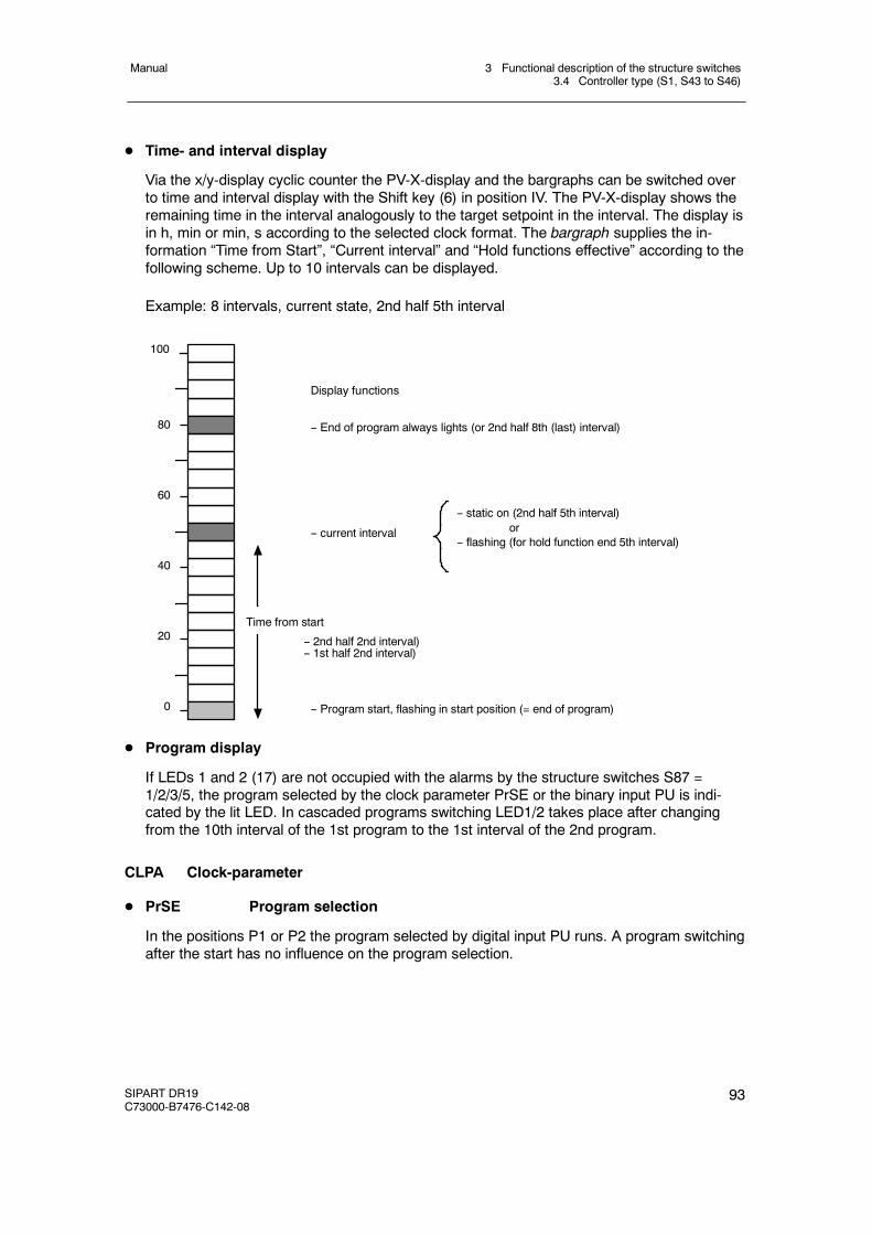
3 Functional description of the structure switches3.4 Controller type (S1, S43 to S46)
Manual
SIPART DR19C73000-B7476-C142-08
93
D Time- and interval display
Via the x/y-display cyclic counter the PV-X-display and the bargraphs can be switched overto time and interval display with the Shift key (6) in position IV. The PV-X-display shows theremaining time in the interval analogously to the target setpoint in the interval. The display isin h, min or min, s according to the selected clock format. The bargraph supplies the in-formation “Time from Start”, “Current interval” and “Hold functions effective” according to thefollowing scheme. Up to 10 intervals can be displayed.
Example: 8 intervals, current state, 2nd half 5th interval
100
80
60
40
20
0
-- End of program always lights (or 2nd half 8th (last) interval)
Time from start
-- current interval
-- Program start, flashing in start position (= end of program)
-- static on (2nd half 5th interval)or
-- flashing (for hold function end 5th interval)
Display functions
-- 2nd half 2nd interval)-- 1st half 2nd interval)
D Program display
If LEDs 1 and 2 (17) are not occupied with the alarms by the structure switches S87 =1/2/3/5, the program selected by the clock parameter PrSE or the binary input PU is indi-cated by the lit LED. In cascaded programs switching LED1/2 takes place after changingfrom the 10th interval of the 1st program to the 1st interval of the 2nd program.
CLPA Clock-parameter
D PrSE Program selection
In the positions P1 or P2 the program selected by digital input PU runs. A program switchingafter the start has no influence on the program selection.
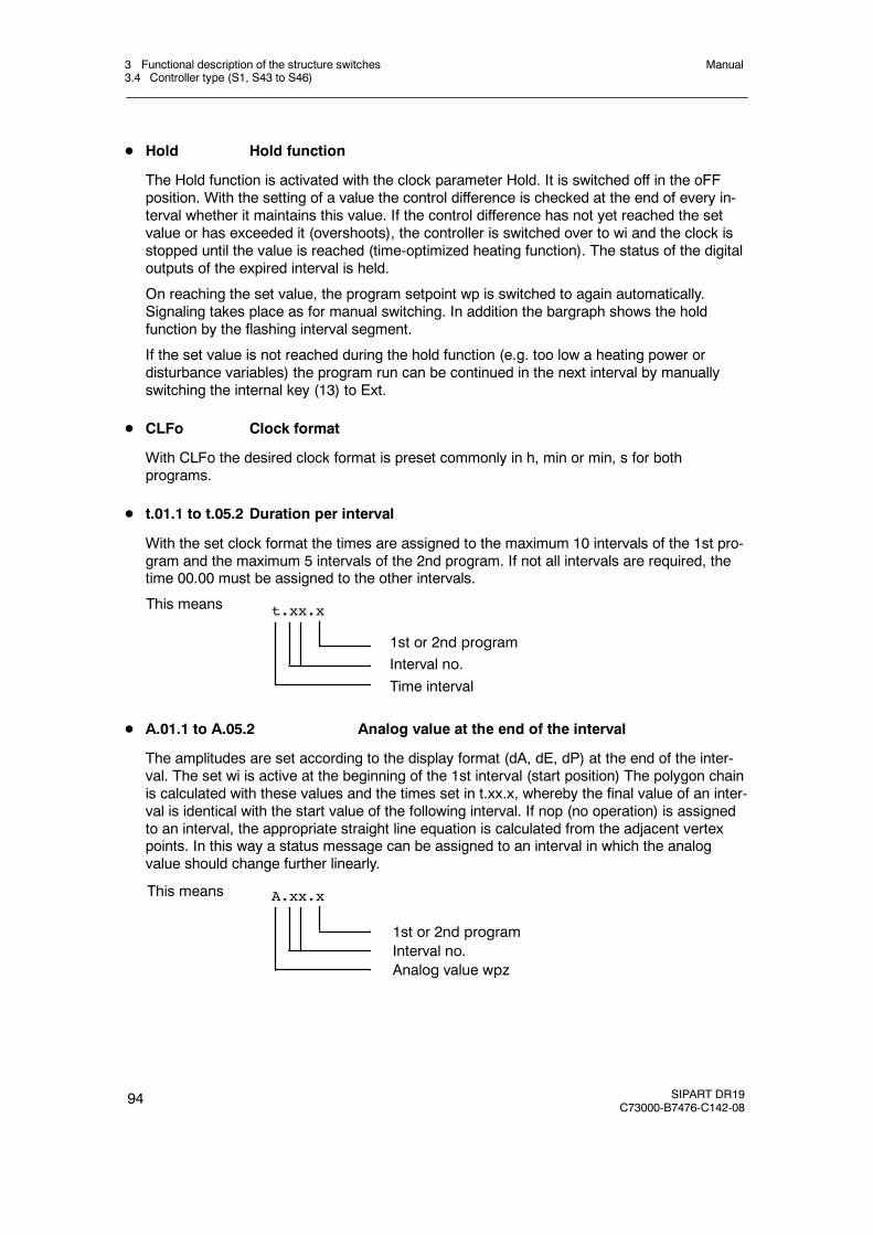
3 Functional description of the structure switches3.4 Controller type (S1, S43 to S46)
Manual
94 SIPART DR19C73000-B7476-C142-08
D Hold Hold function
The Hold function is activated with the clock parameter Hold. It is switched off in the oFFposition. With the setting of a value the control difference is checked at the end of every in-terval whether it maintains this value. If the control difference has not yet reached the setvalue or has exceeded it (overshoots), the controller is switched over to wi and the clock isstopped until the value is reached (time-optimized heating function). The status of the digitaloutputs of the expired interval is held.
On reaching the set value, the program setpoint wp is switched to again automatically.Signaling takes place as for manual switching. In addition the bargraph shows the holdfunction by the flashing interval segment.
If the set value is not reached during the hold function (e.g. too low a heating power ordisturbance variables) the program run can be continued in the next interval by manuallyswitching the internal key (13) to Ext.
D CLFo Clock format
With CLFo the desired clock format is preset commonly in h, min or min, s for bothprograms.
D t.01.1 to t.05.2 Duration per interval
With the set clock format the times are assigned to the maximum 10 intervals of the 1st pro-gram and the maximum 5 intervals of the 2nd program. If not all intervals are required, thetime 00.00 must be assigned to the other intervals.
This means
1st or 2nd programInterval no.Time interval
t.xx.x
D A.01.1 to A.05.2 Analog value at the end of the interval
The amplitudes are set according to the display format (dA, dE, dP) at the end of the inter-val. The set wi is active at the beginning of the 1st interval (start position) The polygon chainis calculated with these values and the times set in t.xx.x, whereby the final value of an inter-val is identical with the start value of the following interval. If nop (no operation) is assignedto an interval, the appropriate straight line equation is calculated from the adjacent vertexpoints. In this way a status message can be assigned to an interval in which the analogvalue should change further linearly.
This means
1st or 2nd programInterval no.Analog value wpz
A.xx.x

3 Functional description of the structure switches3.4 Controller type (S1, S43 to S46)
Manual
SIPART DR19C73000-B7476-C142-08
95
D (CLb)1.01.1 to (CLb)6.05.2 Binary output signal during the interval
A maximum 6 digital outputs CLb1 to CLb6 per interval can be occupied with status mess-ages Low and High. The entered status is active during the whole interval. The status at theend of the program is defined with x.PE.x in the start position. This enables the end of pro-gram alarm to be generated as an edge or a status message.
This means
1st or 2nd programInterval no.Digital output CLbx
x.xx.x
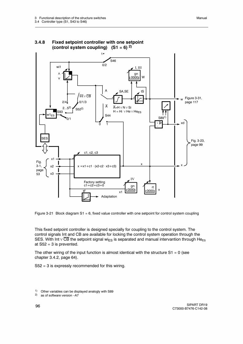
3 Functional description of the structure switches3.4 Controller type (S1, S43 to S46)
Manual
96 SIPART DR19C73000-B7476-C142-08
3.4.8 Fixed setpoint controller with one setpoint(control system coupling) (S1 = 6) 2)
tF
0/2
0
c1, c2, c3
x
1
S46
SA,SE
1
S44
Factory settingc1=c2=c3=0
x =x1+c1 . (x2-c2 . x3+c3)x2
x1
x3
xd
x
I, III
W
A
Adaptation
tS
wi1
x1
w
0/1
2...52)2/4 0/1/3
S522)
w1ES
SES
S93
Int∨CB
A A=H∨N∨SiH = Hi∨He∨HeES
gn0000
+--
x
IV
gn0000
rt0000
Figure 3-31,page 117
Fig. 3-23,page 99
Fig.3-1,page53
<>
S891)
Figure 3-21 Block diagram S1 = 6, fixed value controller with one setpoint for control system coupling
This fixed setpoint controller is designed specially for coupling to the control system. Thecontrol signals Int and CB are available for locking the control system operation through theSES. With Int∨CB the setpoint signal wiES is separated and manual intervantion through HeESat S52 = 3 is prevented.
The other wiring of the input function is almost identical with the structure S1 = 0 (seechapter 3.4.2, page 64).
S52 = 3 is expressly recommended for this wiring.
1) Other variables can be displayed analogly with S892) as of software version –A7
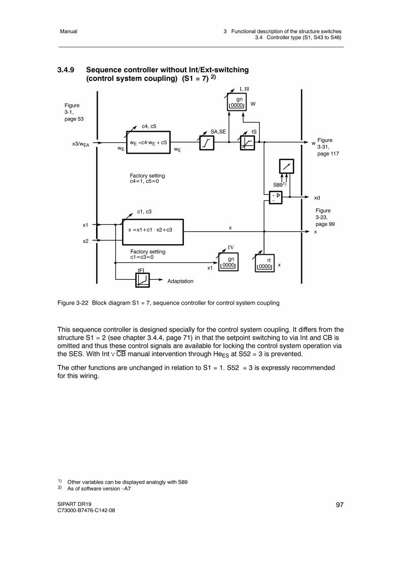
3 Functional description of the structure switches3.4 Controller type (S1, S43 to S46)
Manual
SIPART DR19C73000-B7476-C142-08
97
3.4.9 Sequence controller without Int/Ext-switching(control system coupling) (S1 = 7) 2)
tFI
c1, c3
x
SA,SE
Factory settingc1=c3=0
x =x1+c1 . x2+c3x1
xd
x
Adaptation
tS
x1
w
c4, c5
Factory settingc4=1, c5=0
wE =c4·wE + c5wE
x2
I, III
Wgn
0000
+--
x3/wEA
IV
gn0000
rt0000 x
Figure3-31,page 117
Figure3-23,page 99
Figure3-1,page 53
wE
S891)
Figure 3-22 Block diagram S1 = 7, sequence controller for control system coupling
This sequence controller is designed specially for the control system coupling. It differs from thestructure S1 = 2 (see chapter 3.4.4, page 71) in that the setpoint switching to via Int and CB isomitted and thus these control signals are available for locking the control system operation viathe SES. With Int∨CB manual intervention through HeES at S52 = 3 is prevented.
The other functions are unchanged in relation to S1 = 1. S52 = 3 is expressly recommendedfor this wiring.
1) Other variables can be displayed analogly with S892) As of software version –A7
3 Functional description of the structure switches3.5 Control algorithm
Manual
98 SIPART DR19C73000-B7476-C142-08
3.5 Control algorithm
D Control algorithm
The PID control algorithm is implemented as an interaction-free parallel structure and followsthe ideal controller equations whilst neglecting the filter constants and the cycle time.
- P-controller
ya =Kp ⋅ xd + yo or yaxd =Kp
- PI-controller
ya =Kp (xd + xd dt) +yo(t) or =Kp (1 + )1Tn t0
yaxd
1j ⋅ Tn
- D-element-connection (zD-part)
The D-element connection can be added optionally.yaE Tv
vv
= Kp j ⋅ Tv
1 + j ⋅
The input variable E for the D-element is S48 xd, x, x1, -z, or +z depending on theposition of S48.
- z-connectionThe z-part can be added optionally to the controller output ya.
ya =c6 ⋅ z or yaz = c6
D Controller direction of effect
The controller direction of effect is set with S47. It must always have the opposite behavior(negative follow-up) to the controlled system (including actuator and transmitter).
S47= 0, normal direction controller (+Kp, rising x causes falling y) for normal directioncontrolled systems (rising y causes rising x),
S47= 1, reverse direction controller (--Kp, rising x causes rising y) for reverse directioncontrolled systems (rising y causes falling x),
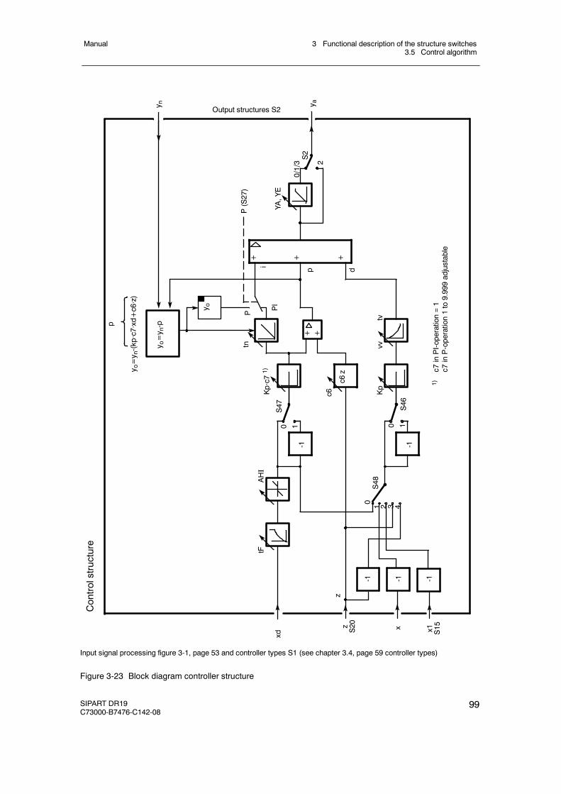
3 Functional description of the structure switches3.5 Control algorithm
Manual
SIPART DR19C73000-B7476-C142-08
99
z S20 x1 S15x
2
y n y a
S48
c6Kp·c71)
i
Ptn
S2
P(S27)
Kp
S46
S47
0
AHI
tF
0/1/3
0 10 1
+ + +
-1
c6z
y o
YA,YE
y o=y n-(kp·c7·xd+c6·z)
Controlstructure
1 2 3 4
xd
p
1)c7
inPI-operation=1
c7inP-operation1to9.999adjustable
-1 -1 -1
-1
vvtv
+
Output structures S2
+p d
y o=y n-p
z
PI
Input signal processing figure 3-1, page 53 and controller types S1 (see chapter 3.4, page 59 controller types)
Figure 3-23 Block diagram controller structure
3 Functional description of the structure switches3.5 Control algorithm
Manual
100 SIPART DR19C73000-B7476-C142-08
D Operating point yo for P-controllers
The operating point yo of the P-controller can be set either automatically or as a parameter(onPA).
Automatic working point (Yo = Auto)
Whenever there is no automatic operation (manual-, tracking-, safety- or blocking operation)the operating point yo is tracked so that switching to automatic operation is bumpless.This gives an automatic setting of the operating point yo in manual mode:
yo = yH - (Kp · c7 · (w - xH) + c6 · z)
If the actual value in manual mode (xH) is driven to the desired setpoint w by the appropriatemanual manipulated variable yH, the operating point yo is identical to the manual manipu-lated variable yH.
yo = yH or yo = yH + c6 · z.
Fixed working point (Yo = 0 to 100 %)
The controller operates in all operating modes with the working point set as a permanentparameter.
D Manipulated variable limit YA, YE
The manipulated variable limiting with parameters YA and YE is active depending on theswitch position of S54 only in automatic operation or in all operating modes. The limits ofthese parameters are at -10 and +110 %. However, it should be taken into account that thecontroller neither outputs negative actuating currents nor detects any negative position feed-back signals.
If the manipulated variable ya reaches one of the limits YA or YE in the limited operatingmode, further integration is aborted to avoid integral saturation. This ensures that the ma-nipulated variable can be changed immediately after reversing the polarity.
In manual-, tracking- (DDC) or safety mode the manipulated variable y can be driven out ofthe limiting range at S54 = 0 (limiting only in automatic mode). When switching to automaticoperation the last manipulated variable is then transferred bumplessly but only changes inthe manipulated variable in the direction of the YA to YE range are subsequently executed.
The manipulated variable limiting is possible in K-, two-position and three-position steppercontrollers with external position feedback (S2 = 0, 1, 3).
3 Functional description of the structure switches3.6 Controller output structures (S2, S50 to S56)
Manual
SIPART DR19C73000-B7476-C142-08
101
D Bumpless switching to automatic mode
If there is no automatic operation (manual, tracking, safety or active blocking operation) theI-part or the operating point yo (only at Yo = Auto) is tracked so that the switching to auto-matic operation is bumpless. Any still active D-part is set to zero.
D P-PI-switching
With the control signal P = 1, the controller is switched from PI- to P-behavior, at Yo = Auto,the switching is bumpless.
3.6 Controller output structures (S2, S50 to S56)
The controller structures follow four different controller output structures depending on structureswitch S2.
S2=0 K-controllerS2=1 two-position controller with 2 S-outputs heating/cooling, optionally 1 K-outputS2=2 three-position-(S)-controller with internal feedbackS2=3 three-position-(S)-controller with external feedback
D S2=0: Continuous (K) controller (figure 3-24, page 103 and figure 3-25, page 104)
To control proportional active actuators (e.g. pneumatic actuators or I/P-transformers) or ascommand controllers in cascades.
Actuating time tP, tM (onPA)
The setting speed of the automatic manipulated variable is set with the parameters tP andtM. In the oFF position, no limiting takes place, in positions 1 to 1000 s the minimum actuat-ing time for 0 to 100 % manipulated variable is preset. Whereby tP acts during increase andtM during decrease of the manipulated variable. The P-, I- and D-part as well as the disturb-ance variable z is limited in the rise speed.This setting speed limit is used:
- to avoid integral saturations in the floating times of the following actuator >1 s- to avoid hard output surges of the P-, D- and z-part.
In this case it must be taken into account that the control time is greater.
3 Functional description of the structure switches3.6 Controller output structures (S2, S50 to S56)
Manual
102 SIPART DR19C73000-B7476-C142-08
D S2 = 1: two-position controller with two S-outputs heating/cooling;optionally with one K-output
This output structure is identical to the K-output structure in its switching options (see fig-ure 3-24, page103 and figure 3-25, page104).
The output variable can only adopt two states for every switching output + Δy, -Δy. Switchingon or switching off. The relationship between switching on- and switching off is defined as
setting ratio =switch-on duration
switch-on duration + switch-off duration
Switch on duration and switch off duration together give the period duration.
The setting range y from 0 to 100 % can be divided into two sub-ranges. The range Y1 witha falling characteristic for cooling, the range 100% Y2 with rising characteristic for heating.Two pulse stages are connected in series which transform the two sub manipulated vari-ables into pulse-pause ratio. It is possible to use the manipulated variable limiting of y withthe parameters yA and yE, the setting ratio 1 is then not reached. Since the minimum pulseduration or pause can be set by tA or tE, further limiting is not normally necessary. A deadzone can be set between these two sub manipulated variables. By changing Y1 or Y2(oFPA) the dead zone is preset and the slope adapted to the cooling or heating aggregate.
Factory setting Y1 = Y2 = 50 % corresponds to dead zone = 0 %.
Every sub manipulated variable can be assigned a different period duration tP and tM(onPA). The setting ratio 0 to 1 is run through in every section, whereby the shortest turn-onor turn-off time is set with tE and tA (onPA). The period duration must be set so that the re-spective best compromise between the minimum permissible switch on duration of theactuator (e.g. contactor, solenoid valve, fan, cooling compressor), the switching frequencyand the resulting curve of the controller variable is found.
One of the partial manipulated variables Y1 or Y2 can be output as an analog manipulatedvariable by structure switch S57 (as of software version –B5).
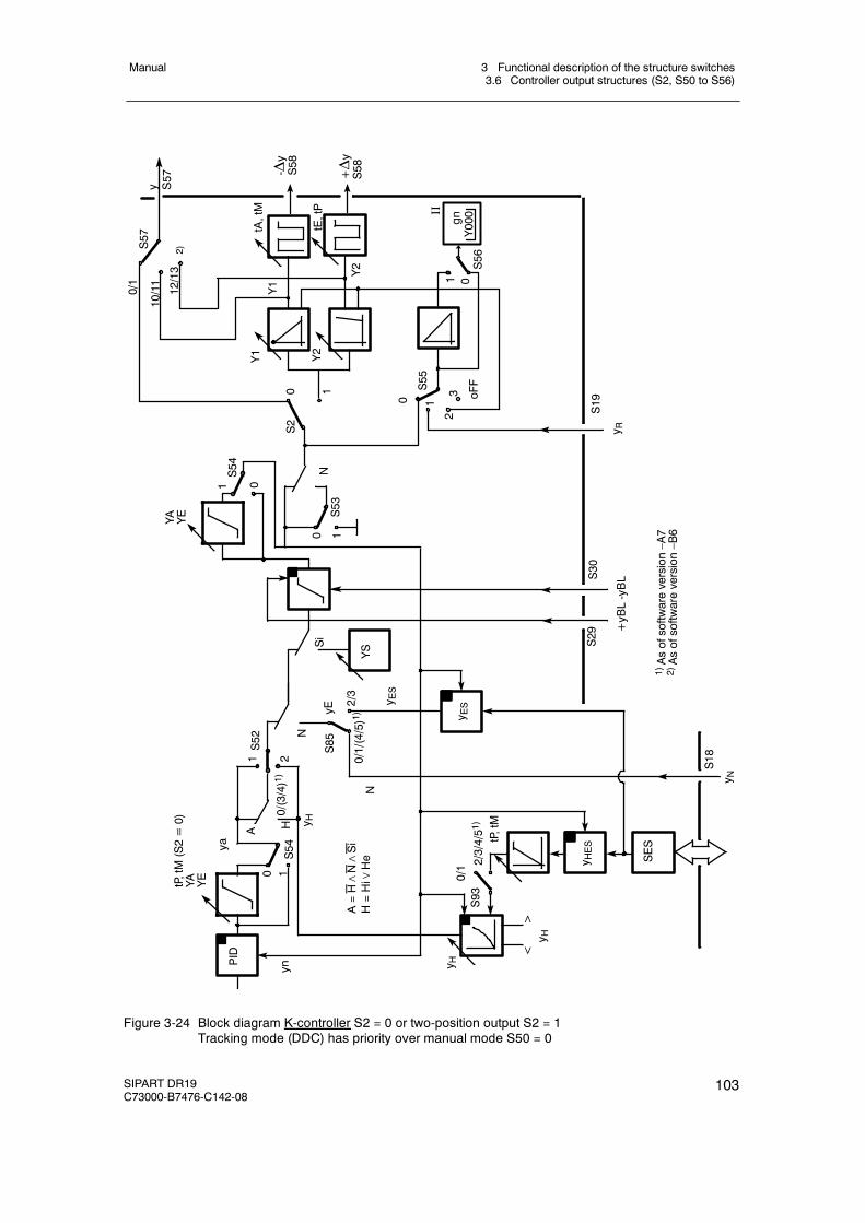
3 Functional description of the structure switches3.6 Controller output structures (S2, S50 to S56)
Manual
SIPART DR19C73000-B7476-C142-08
103
NtE,tP
tA,tM
S52
S55
2
1
S85
Y1 Y2
+yBL-yBL
oFF
2/3
2 0/1/(4/5)1)
1
1
1
0
0
0
S56
S53
NSi
yn
A
ya
tP,tM(S2=0)
YA YE
H
YS
-Δy
S58
S54
10
YA YE
30 1
S2
+Δy
S58
1 0
S54
S29
S30
S19
PID
0/(3/4)1)
<>
S18
SES
0/1 2/3/4/51)
S93
tP,tM
1)Asofsoftwareversion–A7
2)Asofsoftwareversion–B6
N
y R
y N
y H
y H
A=H∧N∧Si
H=Hi∨
He
y H
y ES
y HES
y ES
y S57
12/13
10/11
0/1
S57
Y1
Y2
yE
II
gnY000
2)
Figure 3-24 Block diagram K-controller S2 = 0 or two-position output S2 = 1Tracking mode (DDC) has priority over manual mode S50 = 0
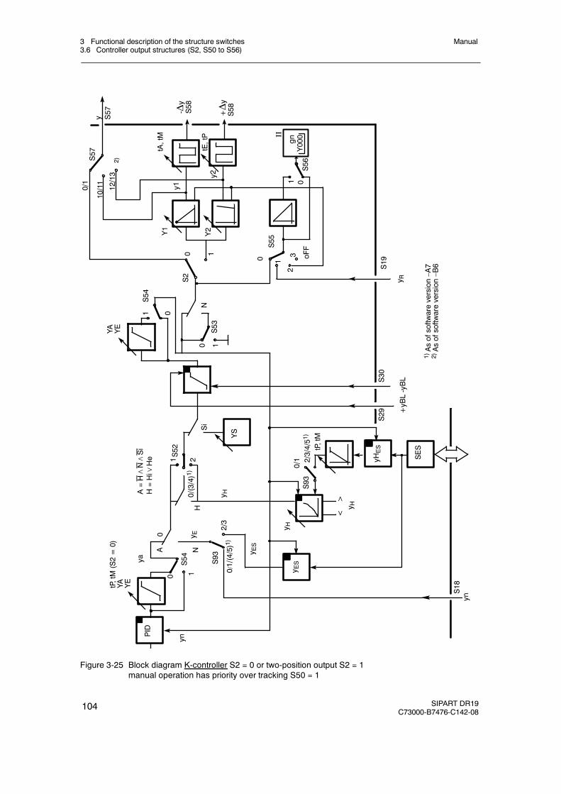
3 Functional description of the structure switches3.6 Controller output structures (S2, S50 to S56)
Manual
104 SIPART DR19C73000-B7476-C142-08
NN
S29
S52
S93
+yBL-yBL
2/3
0
2
0 /1/(4/5)1)
1
1
0
S53
Si
yn
A
ya
tP,tM(S2=0)
YA YE
YS
S54
10
YA YE
1 0
S54
S30
0/(3/4)1)
<>
SES
0/1 2/3/4/51)
S93
tP,tM
S18
HtE,tP
tA,tM
S55
2
1
Y1 Y2
oFF
1 0
0
S56
-Δy
S58
30 1
+Δy
S58
S19
y1
y2
y R
yHES
PID
y H
y H
y E
y ES
y HA=H∧N∧Si
H=Hi∨
He
y ES
yn
y S57
12/13
10/11
0/1
S57
S2
1)Asofsoftwareversion–A7
2)Asofsoftwareversion–B6
2)
II
gnY000
Figure 3-25 Block diagram K-controller S2 = 0 or two-position output S2 = 1manual operation has priority over tracking S50 = 1
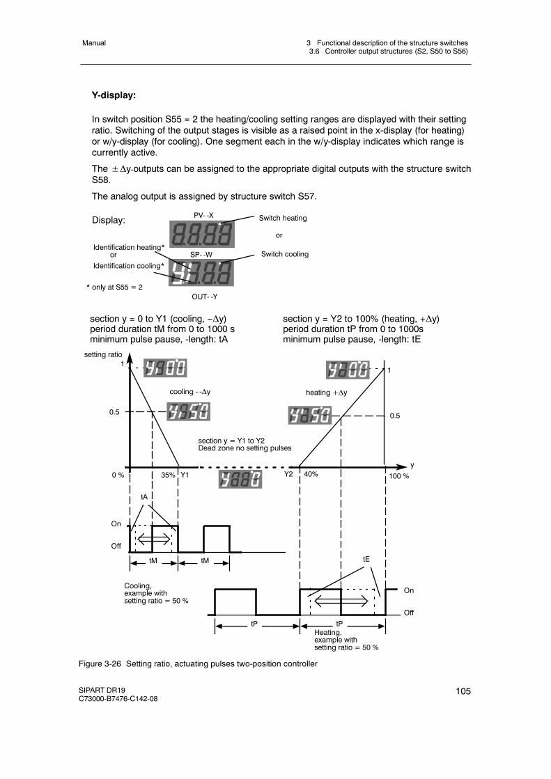
3 Functional description of the structure switches3.6 Controller output structures (S2, S50 to S56)
Manual
SIPART DR19C73000-B7476-C142-08
105
Y-display:
In switch position S55 = 2 the heating/cooling setting ranges are displayed with their settingratio. Switching of the output stages is visible as a raised point in the x-display (for heating)or w/y-display (for cooling). One segment each in the w/y-display indicates which range iscurrently active.
The±Δy-outputs can be assigned to the appropriate digital outputs with the structure switchS58.
The analog output is assigned by structure switch S57.
Display: PV- -X Switch heating
SP- -W Switch cooling
OUT- -Y
Identification heating*or
Identification cooling*
* only at S55 = 2
or
section y = 0 to Y1 (cooling, --Δy)period duration tM from 0 to 1000 sminimum pulse pause, -length: tA
section y = Y2 to 100% (heating, +Δy)period duration tP from 0 to 1000sminimum pulse pause, -length: tE
setting ratio
y
11
0.5 0.5
100 %40%0 % Y135% Y2
section y = Y1 to Y2Dead zone no setting pulses
tA
tE
On
Off
On
Off
tM tM
tP tP
Cooling,example withsetting ratio = 50 %
Heating,example withsetting ratio = 50 %
cooling - -Δy heating +Δy
Figure 3-26 Setting ratio, actuating pulses two-position controller
3 Functional description of the structure switches3.6 Controller output structures (S2, S50 to S56)
Manual
106 SIPART DR19C73000-B7476-C142-08
D S2 = 2: Three-position stepper-(S)-controller with internal feedback
see figure 3-27, page 107 and figure 3-28, page 108
To control I-acting motorized actuating drives.
In S-controllers with internal feedback the K-controller is followed by an internal position con-troller. The positioning control circuit consists of a comparator with following three-positionswitch with hysteresis and an integrator in the feedback. The I-function of the actuator issimulated by the integrator with adjustable floating time tY (parameterization mode onPA)which replaces the position feedback. To ensure the internal integrator and the K-controlleroutput do not drift apart or into saturation in time, both are set back rhythmically by the sameamount (synchronized). The y-output is only a relative manipulated variable. It is thereforenot possible to perform a manipulated variable limiting of YA and an absolute value preset ofYE und YS. The safety manipulated variable YS is specified as a direction-dependent con-tinuous contact. At YS≤50 % (oFPA) -Δy switches, at YS > 50 %, +Δy switches to continu-ous contact so that the end positions of the actuator represent the safety position. The posi-tion controller has an adjustable minimum pulse length (tE) and-pause (tA) with which theresponse threshold of the position controller is set indirectly:
- Switching on Aee = 2100 % ⋅ tE
tY
- Switching off Aea =100 % ⋅ tE
tY
- Hysteresis Aee -- Aea =100 % ⋅ tE
tY
- Pause Aa =100 % ⋅ tA
tY
- tY = tP, tM set floating time (parameterization mode onPA)
Aee must be set up after a pulse pause at least as a deviation until an actuating pulse withlength tE is output. Aea can remain as a constant control error of the position control circuit.
Aa can be set up after an actuating pulse as a deviation until an actuating pulse is output inthe same or opposite direction. When time tA has expired, the position controller reacts ac-cordingly to the set tE.
Setting criteria of tA and tE, see chapter 6.3, page 205.
The position feedback yR is only used to display the manipulated variable in S-controllerswith internal feedback. If they are not connected, S55 is set to 3, the manipulated variabledisplay is then dark.
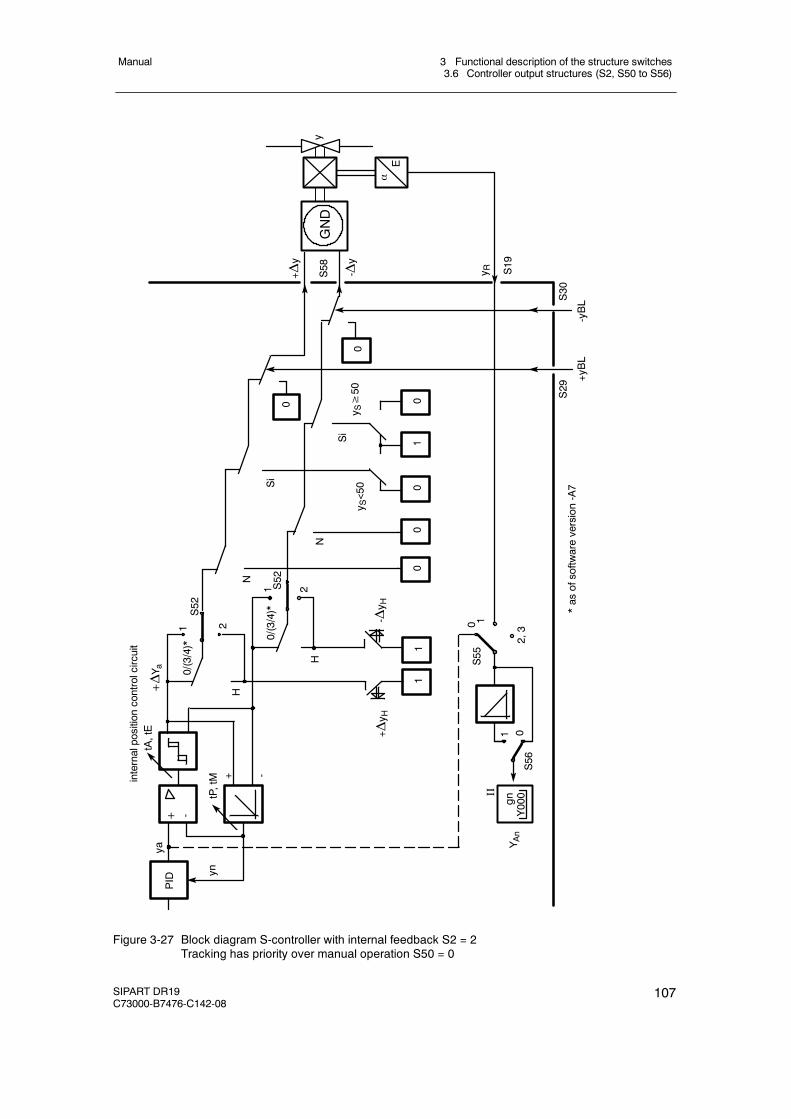
3 Functional description of the structure switches3.6 Controller output structures (S2, S50 to S56)
Manual
SIPART DR19C73000-B7476-C142-08
107
1
02,3
S55
1
S56
2
S52
1
H
2S52
1
H
+ Δy H
-Δy H
N
N
Si
Siy S≥50
+yBL
-yBL
+ -PID
+ -
tP,tM
tA,tE
internalpositioncontrolcircuit
+ΔY a
yn
ya
0/(3/4)*
S30
S29
*asofsoftwareversion-A7
0/(3/4)*
y S<50
- Δy
y R+Δy
S19
S58
αE
y
0
YAn
11
10
00
0
0
II
gnY000
0
GND
Figure 3-27 Block diagram S-controller with internal feedback S2 = 2Tracking has priority over manual operation S50 = 0
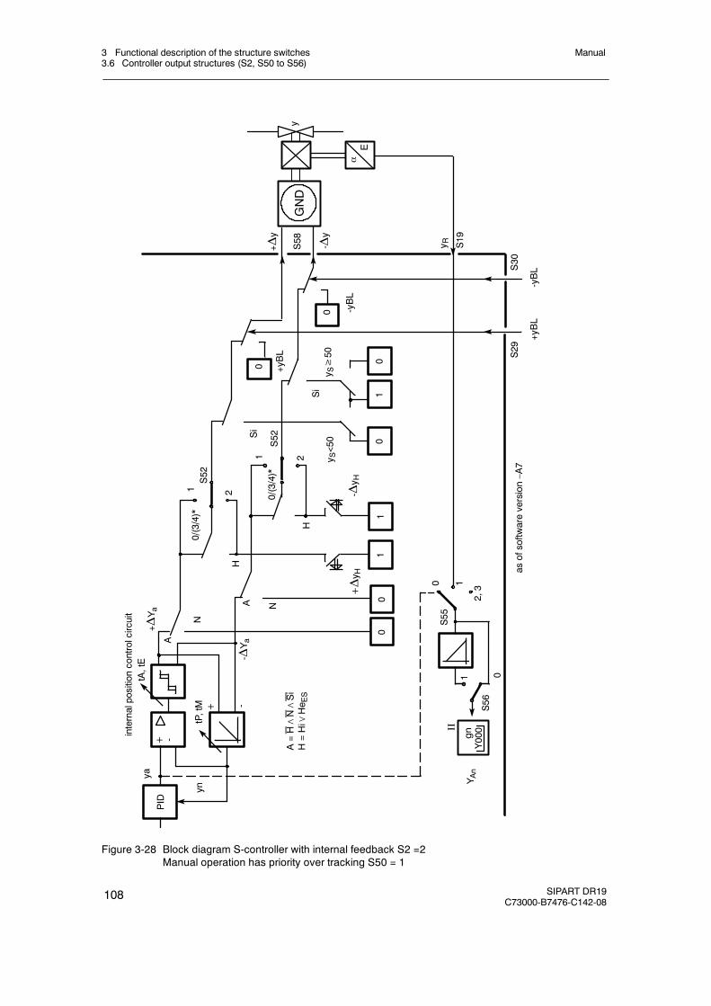
3 Functional description of the structure switches3.6 Controller output structures (S2, S50 to S56)
Manual
108 SIPART DR19C73000-B7476-C142-08
0 1
0
2,3
S55
1
S56
2
S52
0
00
0
1
A
2
S52
1
H
+Δy H
-Δy H
N
N
Si
Si
+ -
+ -
tP,tM
tA,tE
internalpositioncontrolcircuit
+ΔYa
A-Δ
Ya
H
yn
ya
0/(3/4)*
S29
asofsoftwareversion–A7
0/(3/4)*
0
S30
-Δy
y R+Δy
S19
S58
αE
yGND
PID
YAn
A=H∧N∧Si
H=Hi∨
He E
S
+yBL
-yBL
01
11
-yBL
y S≥50
y S<50
II
gnY000
+yBL
Figure 3-28 Block diagram S-controller with internal feedback S2 =2Manual operation has priority over tracking S50 = 1
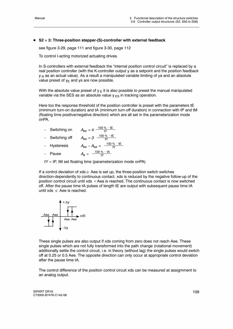
3 Functional description of the structure switches3.6 Controller output structures (S2, S50 to S56)
Manual
SIPART DR19C73000-B7476-C142-08
109
D S2 = 3: Three-position stepper-(S)-controller with external feedback
see figure 3-29, page 111 and figure 3-30, page 112
To control I-acting motorized actuating drives.
In S-controllers with external feedback the “internal position control circuit” is replaced by areal position controller (with the K-controller output y as a setpoint and the position feedbacky R as an actual value). As a result a manipulated variable limiting of ya and an absolutevalue preset of yE and ys are now possible.
With the absolute value preset of y E it is also possible to preset the manual manipulatedvariable via the SES as an absolute value y ES in tracking operation.
Here too the response threshold of the position controller is preset with the parameters tE(minimum turn-on duration) and tA (minimum turn-off duration) in connection with tP and tM(floating time positive/negative direction) which are all set in the parameterization modeonPA.
- Switching on Aee = 4100 % ⋅ tE
tY
- Switching off Aea = 3100 % ⋅ tE
tY
- Hysteresis Aee -- Aea =100 % ⋅ tE
tY
- Pause Aa =100 % ⋅ tA
tY
tY = tP, tM set floating time (parameterization mode onPA)
If a control deviation of xds≥ Aee is set up, the three-position switch switchesdirection-dependently to continuous contact. xds is reduced by the negative follow-up of theposition control circuit until xds<Aea is reached. The continuous contact is now switchedoff. After the pause time tA pulses of length tE are output with subsequent pause time tAuntil xds≤ Aee is reached.
-Aea -AeeAea Aee
-Δy
+Δy
xdS
These single pulses are also output if xds coming from zero does not reach Aee. Thesesingle pulses which are not fully transformed into the path change (rotational movement)additionally settle the control circuit, i.e. in theory (without lag) the single pulses would switchoff at 0.25 or 0.5 Aee. The opposite direction can only occur at appropriate control deviationafter the pause time tA.
The control difference of the position control circuit xds can be measured at assigmment toan analog output.
3 Functional description of the structure switches3.6 Controller output structures (S2, S50 to S56)
Manual
110 SIPART DR19C73000-B7476-C142-08
The manual adjustment is made as an incremental adjustment by far overranging of thethree-position switch so that manual adjustment is also possible when the position feedbackis interrupted.
To simplify commissioning of the position control circuit, the manual manipulated variable ispreset absolutely at S55=0 (manipulated variable of the K-controller) so that at this structureswitch position the setpoint of the position control circuit is changed continuously by themanual manipulated variable in order to perform optimization (see chapter 6.2, page 205). Itshould be taken into account here that the manual manipulated variable which is also dis-played is changed faster by the floating time tY than the active manipulated variable on theactuator and a lag therefore takes place. The leveling state can be observed by the Δy-LEDs(12) in the x-display (1) and w/y-display (2). S55 must be set to 1 after optimization to dis-play the active manipulated variable by the position feedback yR.
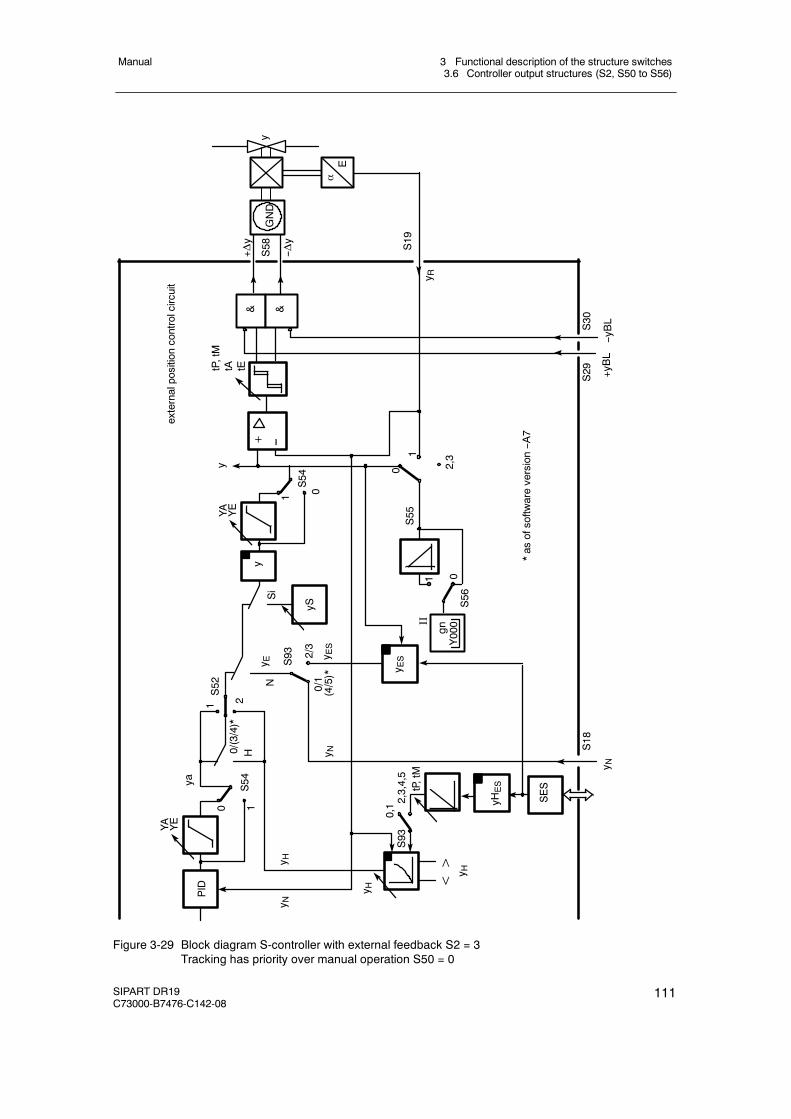
3 Functional description of the structure switches3.6 Controller output structures (S2, S50 to S56)
Manual
SIPART DR19C73000-B7476-C142-08
111
Si
0/1
2/3
YA
0,1
tP,tM
SES
<>
YE
PID
12
S52
H
ya
yS
y ESy E
S
y EN
yHES
y H
& &
--yBL
+yBL
αE
--Δy
+Δy
y
S19
y R
2,3,4,5
S93
y H
y Ny H
y
2,31
0S55
01
S56
externalpositioncontrolcircuit
y
+
y N
S18
0
S54
0/(3/4)*
1
(4/5)*
S93
y N
1 0S54
YA YE
S29
S30
S58
GND
tP,tM
tA tE
*as
ofsoftw
areversion--A
7
II
gnY000
--
Figure 3-29 Block diagram S-controller with external feedback S2 = 3Tracking has priority over manual operation S50 = 0
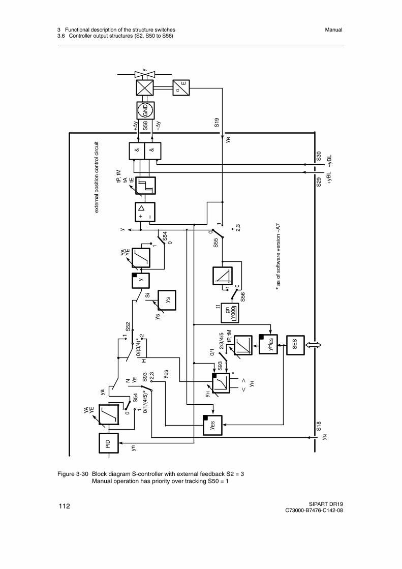
3 Functional description of the structure switches3.6 Controller output structures (S2, S50 to S56)
Manual
112 SIPART DR19C73000-B7476-C142-08
N y ES52
0/(3/4)*
1
0 0/1/(4/5)*
2,3
yn1 2
ya
YA YE
PID
0/1 2/3/4/5
S93
S54
Si
y S
& &
--yBL
+yBL
αE
--Δy
+Δy
y
S19
y R
y
2,31
0S55
01
S56
externalpositioncontrolcircuit
y
+
1 0S54
YA YE
S29
S30
S58
GND
SES
yHES
<> y H
y ES
y H
y ES
tP,tM
tA tE
*as
ofsoftw
areversion--A
7
y NS18
*
y S
S93
tP,tM
II
gnY000
H--
Figure 3-30 Block diagram S-controller with external feedback S2 = 3Manual operation has priority over tracking S50 = 1
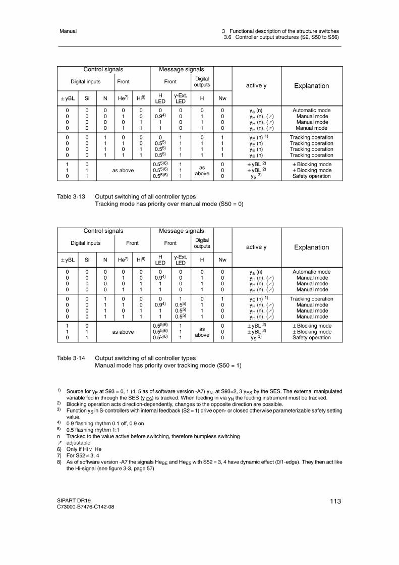
3 Functional description of the structure switches3.6 Controller output structures (S2, S50 to S56)
Manual
SIPART DR19C73000-B7476-C142-08
113
Control signals Message signals
Digital inputs Front Front Digitaloutputs active y Explanation
yBL Si N He7) Hi8) HLED
y-Ext.LED H Nw
y p
0000
0000
0000
0101
0011
00.94)11
0000
0111
0000
ya (n)yH (n), (↗)yH (n), (↗)yH (n), (↗)
Automatic modeManual modeManual modeManual mode
0000
0000
1111
0101
0011
00.55)0.55)0.55)
1111
0111
1111
yE (n) 1)yE (n)yE (n)yE (n)
Tracking operationTracking operationTracking operationTracking operation
110
011
as above0.55)6)0.55)6)0.55)6)
111
asabove
000
yBL 2)
yBL 2)
yS 3)
Blocking modeBlocking modeSafety operation
Table 3-13 Output switching of all controller typesTracking mode has priority over manual mode (S50 = 0)
Control signals Message signals
Digital inputs Front Front Digitaloutputs active y Explanation
yBL Si N He7) Hi8) HLED
y-Ext.LED H Nw
y p
0000
0000
0000
0101
0011
00.94)11
0000
0111
0000
ya (n)yH (n), (↗)yH (n), (↗)yH (n), (↗)
Automatic modeManual modeManual modeManual mode
0000
0000
1111
0101
0011
00.94)11
10.55)0.55)0.55)
0111
1000
yE (n) 1)yH (n), (↗)yH (n), (↗)yH (n), (↗)
Tracking operationManual modeManual modeManual mode
110
011
as above0.55)6)0.55)6)0.55)6)
111
asabove
000
yBL 2)
yBL 2)
yS 3)
Blocking modeBlocking modeSafety operation
Table 3-14 Output switching of all controller typesManual mode has priority over tracking mode (S50 = 1)
1) Source for yE at S93 = 0, 1 (4, 5 as of software version -A7) yN, at S93=2, 3 yES by the SES. The external manipulatedvariable fed in through the SES (y ES) is tracked. When feeding in via yN the feeding instrument must be tracked.
2) Blocking operation acts direction-dependently, changes to the opposite direction are possible.3) Function yS in S-controllers with internal feedback (S2 = 1) drive open- or closed otherwise parameterizable safety setting
value.4) 0.9 flashing rhythm 0.1 off, 0.9 on5) 0.5 flashing rhythm 1:1n Tracked to the value active before switching, therefore bumpless switching↗ adjustable6) Only if Hi∨ He7) For S52≠3, 48) As of software version -A7 the signals HeBE and HeES with S52 = 3, 4 have dynamic effect (0/1-edge). They then act like
the Hi-signal (see figure 3-3, page 57)
3 Functional description of the structure switches3.6 Controller output structures (S2, S50 to S56)
Manual
114 SIPART DR19C73000-B7476-C142-08
D Automatic mode (y = ya)
Automatic mode is switched off / on with the automatic/manual key or in dynamic switching(S52 = 3,4)1) by He (yellow Manual LED (11). All other control signals He, N, Si and±yBLmust be 0. The automatic manipulated variable is connected through to the controller output.
D Manual mode (y = yH)
Manual operation is switched on by the automatic/manual key (yellow manual LED(11) on)or the control signal He as an OR function. The control signal He acts statically in the struc-ture switch settings S52 = 0,1. At S52 = 3,4 He acts dynamically, i.e. every positive edgecauses a switching process. The control signals Si and±yBL must be 0. If tracking modehas priority over manual mode (S50=0) the control signal N must also be Low. Otherwisetracking operation or safety- or blocking operation become active, the manual-LED thenflashes in 0.5 rhythm as an identification. The manual manipulated variable is switchedthrough to the controller output. The manual manipulated variable is preset in K-controllersas an absolute value, in S-controllers as a positioning increment.
D Tracking mode (y = yE)
The tracking operation is switched on by the control signal N. The control signals Si and±yBL must be 0. If manual mode has priority over tracking mode (S50 = 1) the control sig-nal H = Hi∨He must be = 0.
The external manipulated variable yE is connected through to the controller output. Thesource for yE is preset at S93 = 0, 1, as an absolute value yN. With S93 = 2, 3 the absolutevalue becomes active as an external manipulated variable via the SES (yES).
In S-controllers with internal feedback (S2 = 2), absolute value presets of the manipulatedvariable and thus the tracking operation are not possible.
D Safety operation (y = YS)
The safety operation is switched on by the control signal Si. The control signal±yBL mustbe 0. The safety manipulated variable YS is through connected which can be set as a para-meter in the structuring mode oFPA in the range from -10 to 110 %. In S-controllers with in-ternal feedback (S2 = 2) absolute value preset of the manipulated variable is not possible.When safety operation is active, at YS≤50 % -Δy continuous contact and at YS > 50 % +Δycontinous contact is output so that the actuator drives to the end positions.
D Direction-dependent blocking operation
The blocking operation is controlled by the control signals±yBL. All other control signalshave no function. If a control signal is applied the manipulated variable output is blockeddirection-dependently, i.e. only changes in the opposite direction are allowed. If both controlsignals are applied simultaneously, the output is blocked absolutely. The direction-dependentblocking is necessary especially in S-controllers with internal feedback and actuators withlimit stop switches to avoid integral saturation. If the control circuit is opened on reaching the
1) as of software version –A7
3 Functional description of the structure switches3.6 Controller output structures (S2, S50 to S56)
Manual
SIPART DR19C73000-B7476-C142-08
115
end position of the actuator, further integration of the controller must be prevented in order tobe able to react immediately in the event of control difference reversal.
As described above, the control signals±yBL have priority over Si and H or N. The priorityof H or N can be selected by S50. All these operating modes have priority over automaticoperation.
The switching states are signaled by the LEDs Manual (11) and y-external (10). When man-ual mode is active or preselected (if the priority opeating modes are active), the manual LEDlights up. He = 1 is signaled by a flashing rhythm of 0.9 (control signal) if Hi = 0 (i.e. is inautomatic mode by the manual/automatic switching). When switching the control signal Hefrom 1! 0 the automatic mode becomes active.
Tracking, safety and blocking operation is signaled by the y-external LED. Flashing rhythm0.5 indicates that in “manual operation priority over tracking operation”, manual operation isactive but tracking operation is prepared and after switching to automatic operation also be-comes active.
D Blocking of the manual/automatic switching (S52)
With S52 the manual/automatic switching can be blocked in operating modes automaticmode only or manual mode only. The other operating modes are still possible. Then, trackingmode is only possible if tracking has priority over manual mode (see figure 3-24, page 103).
D Manual operation in case of transmitter fault (S51)
With S51 you can switch over to manual operation in the event of a transmitter groups fault(see chapter 3.2, page 51). Manual operation begins at S51 = 1 with the last y or at S51 = 2with the parameterized YS. In both cases the manual manipulated variable can be adjustedwith the± Δy keys after switching.
D Source and direction of effect of the y-display (S55, S56)
With S55 the y-display is switched to the different display sources or switched off. The abso-lute manipulated variable y or the split range-manipulated variables y1 and y2 in two-positioncontrollers heating/cooling or the position feedback-signal yR in three-position-S-controllerscan be displayed.
With S56 the display direction of effect can be selected rising/falling (see chapter 6.1,page 203).
D Control system coupling via the serial interface
As of software version --A7 a parallel process operation is possible through the serial inter-face in addition to the SPC controller (S1 = 2) in all types of controller. The control signals Intand Hi (via HeES at S52 = 3/4, see chapter 3.3, page 54) and the process variables wi andyH can be written through the serial interface at S93≥2 so that the switching from internal toexternal setpoint and automatic/manual switching is possible in all types of controller. If theinternal setpoint wi or the manual manipulated variable yH is active it can also be changed bythe SES or the adjusting keys on the front panel. Since the SES can only adjust absolutely
3 Functional description of the structure switches3.6 Controller output structures (S2, S50 to S56)
Manual
116 SIPART DR19C73000-B7476-C142-08
and not incrementally, it is advisable to use the setpoint ramp (tS) or the dynamic manipu-lated variable with ty to avoid steps.
This parallel “operation” via the serial interface can be locked at S52 = 3 by RC = Int∨CB(see figure 3-3, page 57). This locking facility for the operation via SES on the controllerfront is only useful in the controller types fixed setpoint controller with a setpoint (S1 = 5) andfollow-up controller without internal/external switching (S1 = 6) because in all other controllertypes both the internal key and the control signal CB have other additional functions.
At S52 = 4 the locking facility is omitted and operation is always parallel to the front keys.
To avoid simultaneous actuation via the controller front and the SES, the last switching ac-tion can be read on the process control system. For this, a status bit is set when writingIntES and HeES which is only reset when the front keys Int or Hi are actuated. By requestingthe status bit, the process control system can issue a warning when the last operation tookplace via the front.
At S92 = 1:
Writing of the status signals SiES... to ...tSHES is locked by RC.
If the last operation was through the SES, the SES warning flashes for 3 s in the w/y-displayon pressing the internal key. This initial pressing of the keys does not activate a switchingfunction, only when the keys are pressed again is the desired switching function triggered.
At S92 = 2:
Writing of the status signals SiES... to ...tSHES is locked by CB.
At S92 = 3: *)
The status signals SiES... to ...tSHES are always accessible via the SES (see figure 3-3,page 57).
*) as of software version C4
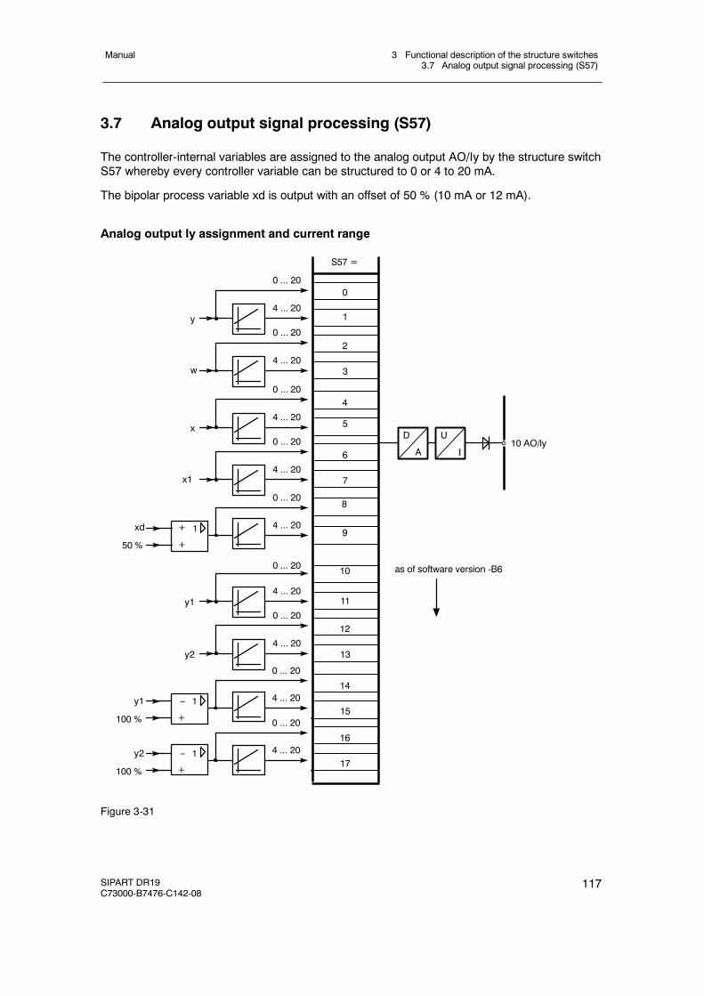
3 Functional description of the structure switches3.7 Analog output signal processing (S57)
Manual
SIPART DR19C73000-B7476-C142-08
117
3.7 Analog output signal processing (S57)
The controller-internal variables are assigned to the analog output AO/Iy by the structure switchS57 whereby every controller variable can be structured to 0 or 4 to 20 mA.
The bipolar process variable xd is output with an offset of 50 % (10 mA or 12 mA).
Analog output Iy assignment and current range
0
S57 =
1
8
9
0 ... 20
0 ... 20
4 ... 20
4 ... 20
U
I
D
A10 AO/ly
+xd
50 %
1
+
0 ... 20
4 ... 20y1
100 %
1
+
2
3
0 ... 20
4 ... 20
4
5
0 ... 20
4 ... 20
6
7
0 ... 20
4 ... 20
10
11
0 ... 20
4 ... 20
12
13
0 ... 20
4 ... 20y2
y1
y
w
x
x1
14
150 ... 20
4 ... 20y2
100 %
1
+
16
17
as of software version -B6
--
--
Figure 3-31
3 Functional description of the structure switches3.8 Digital output signal processing (S58 to S82)
Manual
118 SIPART DR19C73000-B7476-C142-08
3.8 Digital output signal processing (S58 to S82)
The message signals RB, RC ... MUF, +Δw and -Δw are assigned to the digital outputs DO1 toDO8 by the structure switches S59 to S69 and can be negated optionally with the structureswitches S76 to S82 (except +Δw and -Δw).
At S1 = 5 (program controller) the message signals CLb1...6 are also available which can beassigned to the digital outputs with S70 to S75 (see figure 3-32, page 120).
The digital outputs DO1, DO2 and DO7, DO8 of the standard controller can be extended withthe options modules 4DO 24 V +2DI (6DR2801-8E) or 2DO-relay 35 V (6DR2801-8D) in slot 3to a maximum 6 or 8 digital outputs. When using 4DO 24 V +2DI in slot 3 by DO3 to DO6, whenusing 2BA-relay 35 V in slot 3 by DO3 and DO4.When using options modules in slot 3, structure switch S22 must be set according to theassignment, other settings lead to error messages (see chapter 5.5, page 202).
The control signals±Δy (positioning increments of the S-controllers) are not negatable but canbe assigned optionally by S58 to one of the digital outputs DO1, DO2, DO7 or DO8. Setting ofS58 has priority over assignments with S59 to S75. The assigned digital outputs for±Δy arenot stored in “ST5” and “BABE” (refresh-time approx. 20 ms). Decription of ST5 and BABE: seeoperating instructions “Serial SIPART 6DR190x Bus Interface”.
On assigning different control signals to the same digital output an OR-function of the controlsignals is produced (exception at±Δy).
Unassigned digital outputs (switch position 0) are Low and can be set at S93 = 2 by the SES.All digital outputs have wired-or-diodes.
D Functional explanation of the digital message signals.
RB No computer standby of the controllerThis signal indicates that the controller is in internal operation, i.e. not incomputer standby.
RC Computer operationThis signal indicates the negated computer operation RC = Int∧CB andcontrols the setpoint switching.
H Manual modeThe controller is in manual mode, triggered either by the manual/automaticswitching on the front of the device (Hi) or by the digital output signal He if thecontrol signals Si,±yBL and N (with priority of trackingmode over manualmode) Low.
Nw Tracking operationThe controller is in tracking mode when the control signals Si, ±yBL and H(with priority of manual mode over tracking mode) are Low and the controlsignal N is High.
A1/A2 Alarm 1 and 2 indicate response of the limit value alarms A1 and A2.
A3/A4 Alarm 3 and 4 indicates response of the limit value alarms A3 and A4.
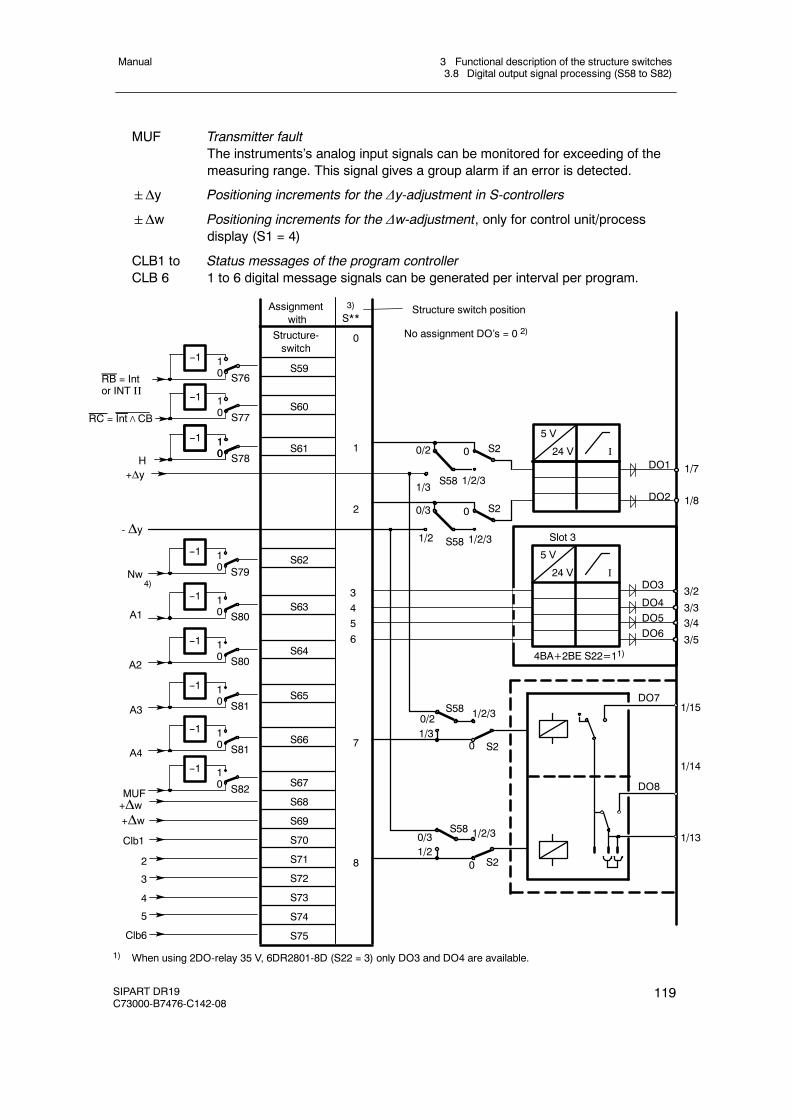
3 Functional description of the structure switches3.8 Digital output signal processing (S58 to S82)
Manual
SIPART DR19C73000-B7476-C142-08
119
MUF Transmitter faultThe instruments’s analog input signals can be monitored for exceeding of themeasuring range. This signal gives a group alarm if an error is detected.
Δy Positioning increments for the Δy-adjustment in S-controllers
Δw Positioning increments for the Δw-adjustment, only for control unit/processdisplay (S1 = 4)
CLB1 to Status messages of the program controllerCLB 6 1 to 6 digital message signals can be generated per interval per program.
No assignment DO’s = 0 2)
3)
S**Assignment
with
S59
S60
S61
S62
S63
S64
S65
S66
- Δy
Nw
A1
A2
A3
A4
MUF
Structure-switch
Structure switch position
DO7
DO8
4)
0/2
1/3
0
1/2/3S58
S2
0/3
1/2
0
1/2/3S58
0/21/3
S58 1/2/3
0 S2
0/31/2
S58 1/2/3
0 S2
S76
10
--1
S77
10
--1
S78
10
--1
RB = Intor INT II
RC = Int∧CB
H+Δy
10
--1
DO1
DO2
1/7
1/8
5 V
24 V I
S79
10
--1
S80
10
--1
S80
10
--1
S81
10
--1
S81
10
--1
S82
10
--1
1
2
3/33/43/5
3/2
5 V
24 V I
Slot 3
DO3
DO4DO5DO6
4BA+2BE S22=11)
3456
1/15
1/14
1/13
7
8
0
S67
S68
S69
S70
S71
S72
S73
+Δw+Δw
Clb1
2
3
4
S74
S75
5
Clb6
S2
1) When using 2DO-relay 35 V, 6DR2801-8D (S22 = 3) only DO3 and DO4 are available.
3 Functional description of the structure switches3.9 Adaptation (S49)
Manual
120 SIPART DR19C73000-B7476-C142-08
2) At S** = 0 there is no assignment, the digithal outputs are then 0 and can be set at S93 = 2 by the SES.3) Assignment of different control signals to one digital output causes an OR-function.4) Message signal active tracking mode see page 118.
Figure 3-32 Assignment of digital outputs (S58 to S82)
3.9 Adaptation (S49)
The adaptation procedure represents a reliable and easy to operate commissioning tool. Theadaptation method is far superior to manual optimization especially on slow controlled systems(high system order). It is activated by the operator and can be aborted at any time in the eventof danger. Overshoots are largely avoided during adaptation. The adaptation method can beaborted without danger at any time.
The controller parameters determined by adaptation become active automatically at the end ofself setting.
In the parameterization mode AdAP, which is only accessible at S49>0, a preselection is madewhether a PI- or a PID-controller is to be designed.
D Adaptation requirements
In order to be able to identify the system reliably the controlled variable must run through atleast 20 % of the control range. For this reason a target setpoint must be preset before start-ing adaptation which is at least 20 % away from the controlled variable’s starting value.
When operating as a two-position controller (S2 = 1), e.g. for operating mode “Heating/Cool-ing”, the split range-foot points Y1, Y2 (oFPA-parameter) must be set according to the fol-lowing instructions.
Y1=0.0 and Y2>0.0 heating onlyY1<100.0 und Y2=100.0 cooling only0.0<Y1 and Y2<100.0 heating and cooling
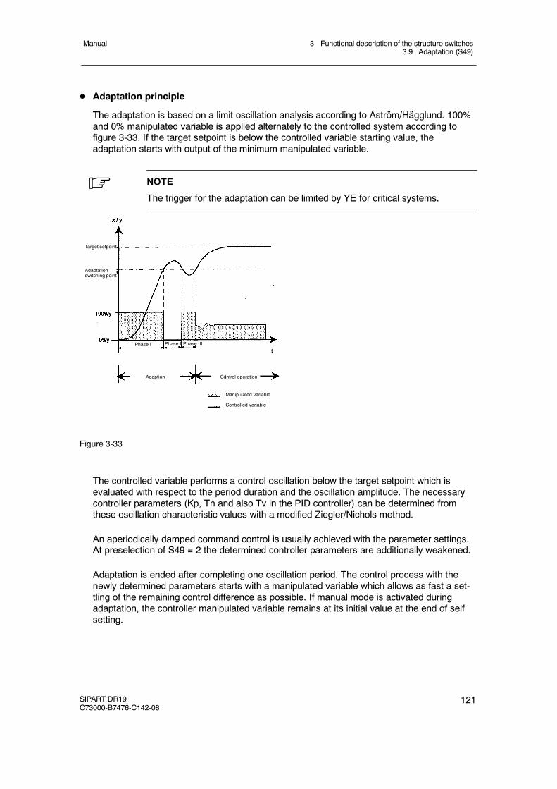
3 Functional description of the structure switches3.9 Adaptation (S49)
Manual
SIPART DR19C73000-B7476-C142-08
121
D Adaptation principle
The adaptation is based on a limit oscillation analysis according to Aström/Hägglund. 100%and 0% manipulated variable is applied alternately to the controlled system according tofigure 3-33. If the target setpoint is below the controlled variable starting value, theadaptation starts with output of the minimum manipulated variable.
. NOTE
The trigger for the adaptation can be limited by YE for critical systems.
Target setpoint
Adaptationswitching point
Adaption Control operation
Manipulated variable
Controlled variable
Phase I Phase IIPhase III
Figure 3-33
The controlled variable performs a control oscillation below the target setpoint which isevaluated with respect to the period duration and the oscillation amplitude. The necessarycontroller parameters (Kp, Tn and also Tv in the PID controller) can be determined fromthese oscillation characteristic values with a modified Ziegler/Nichols method.
An aperiodically damped command control is usually achieved with the parameter settings.At preselection of S49 = 2 the determined controller parameters are additionally weakened.
Adaptation is ended after completing one oscillation period. The control process with thenewly determined parameters starts with a manipulated variable which allows as fast a set-tling of the remaining control difference as possible. If manual mode is activated duringadaptation, the controller manipulated variable remains at its initial value at the end of selfsetting.
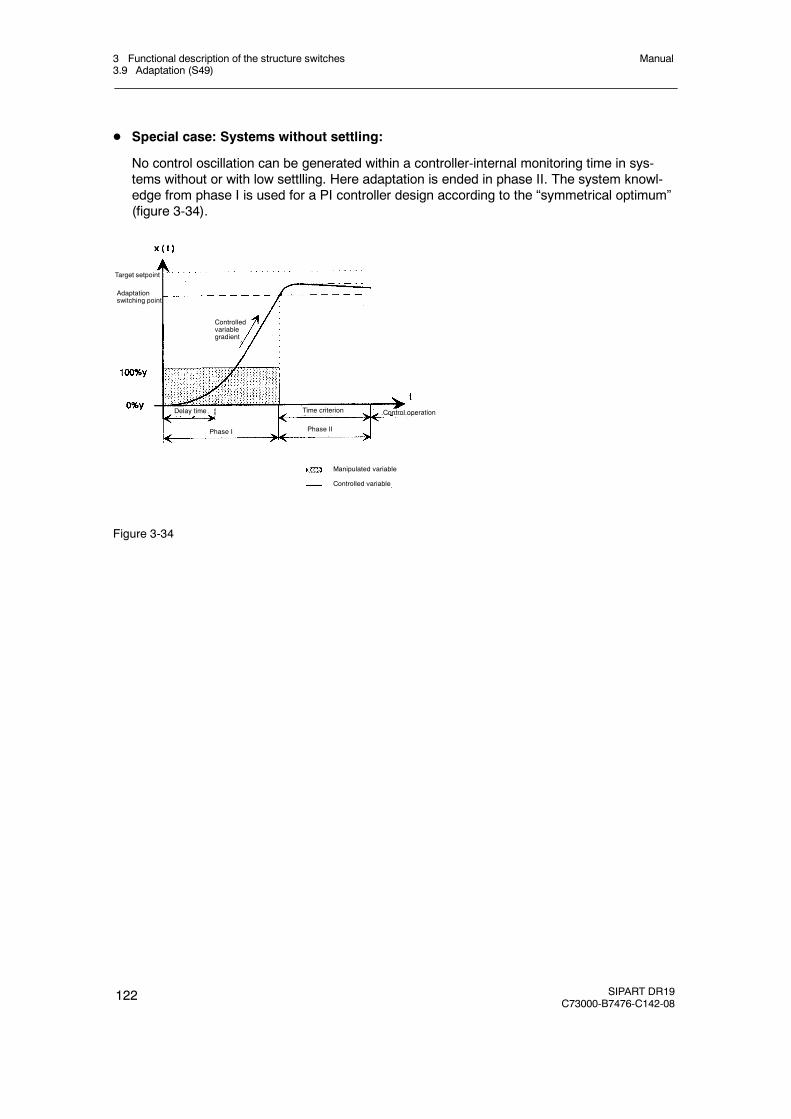
3 Functional description of the structure switches3.9 Adaptation (S49)
Manual
122 SIPART DR19C73000-B7476-C142-08
D Special case: Systems without settling:
No control oscillation can be generated within a controller-internal monitoring time in sys-tems without or with low settlling. Here adaptation is ended in phase II. The system knowl-edge from phase I is used for a PI controller design according to the “symmetrical optimum”(figure 3-34).
Phase I
Target setpoint
Adaptationswitching point
Phase II
Controlledvariablegradient
Control operationTime criterionDelay time
Manipulated variable
Controlled variable
Figure 3-34
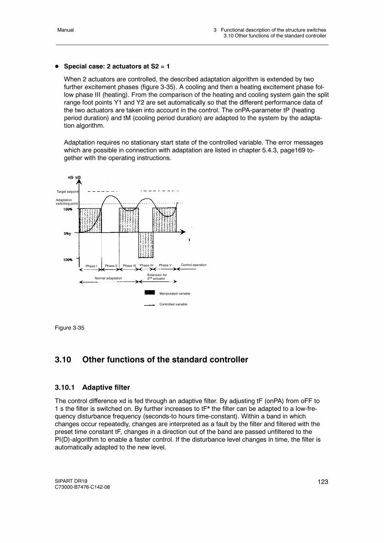
3 Functional description of the structure switches3.10 Other functions of the standard controller
Manual
SIPART DR19C73000-B7476-C142-08
123
D Special case: 2 actuators at S2 = 1
When 2 actuators are controlled, the described adaptation algorithm is extended by twofurther excitement phases (figure 3-35). A cooling and then a heating excitement phase fol-low phase III (heating). From the comparison of the heating and cooling system gain the splitrange foot points Y1 and Y2 are set automatically so that the different performance data ofthe two actuators are taken into account in the control. The onPA-parameter tP (heatingperiod duration) and tM (cooling period duration) are adapted to the system by the adapta-tion algorithm.
Adaptation requires no stationary start state of the controlled variable. The error messageswhich are possible in connection with adaptation are listed in chapter 5.4.3, page169 to-gether with the operating instructions.
Target setpoint
Adaptationswitching point
Phase I Phase II Phase III Phase IV Phase V Control operation
Normal adaptationExtension for2nd actuator
Manipulated variable
Controlled variable
Figure 3-35
3.10 Other functions of the standard controller
3.10.1 Adaptive filter
The control difference xd is fed through an adaptive filter. By adjusting tF (onPA) from oFF to1 s the filter is switched on. By further increases to tF* the filter can be adapted to a low-fre-quency disturbance frequency (seconds-to hours time-constant). Within a band in whichchanges occur repeatedly, changes are interpreted as a fault by the filter and filtered with thepreset time constant tF, changes in a direction out of the band are passed unfiltered to thePI(D)-algorithm to enable a faster control. If the disturbance level changes in time, the filter isautomatically adapted to the new level.
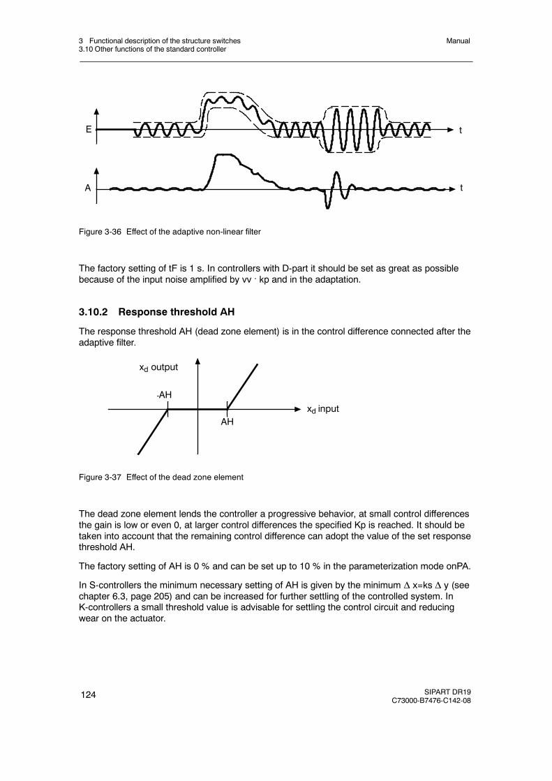
3 Functional description of the structure switches3.10 Other functions of the standard controller
Manual
124 SIPART DR19C73000-B7476-C142-08
E
A t
t
Figure 3-36 Effect of the adaptive non-linear filter
The factory setting of tF is 1 s. In controllers with D-part it should be set as great as possiblebecause of the input noise amplified by vv . kp and in the adaptation.
3.10.2 Response threshold AH
The response threshold AH (dead zone element) is in the control difference connected after theadaptive filter.
-AH
AH
xd output
xd input
Figure 3-37 Effect of the dead zone element
The dead zone element lends the controller a progressive behavior, at small control differencesthe gain is low or even 0, at larger control differences the specified Kp is reached. It should betaken into account that the remaining control difference can adopt the value of the set responsethreshold AH.
The factory setting of AH is 0 % and can be set up to 10 % in the parameterization mode onPA.
In S-controllers the minimum necessary setting of AH is given by the minimum Δ x=ks Δ y (seechapter 6.3, page 205) and can be increased for further settling of the controlled system. InK-controllers a small threshold value is advisable for settling the control circuit and reducingwear on the actuator.
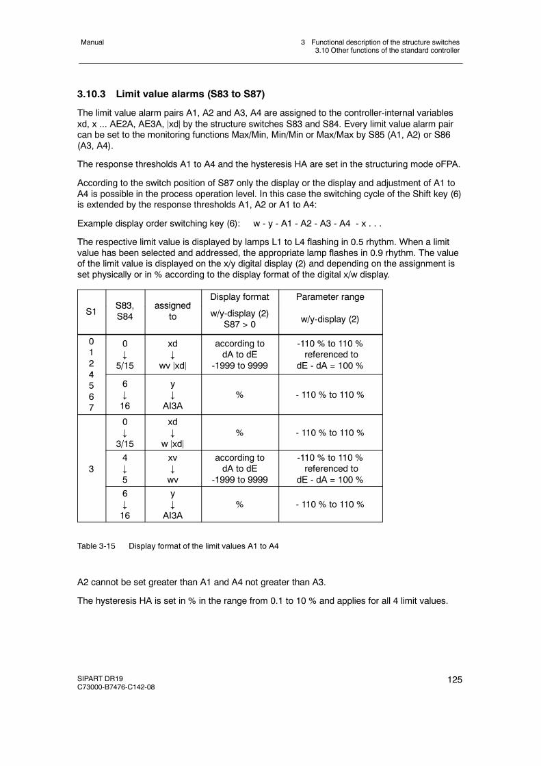
3 Functional description of the structure switches3.10 Other functions of the standard controller
Manual
SIPART DR19C73000-B7476-C142-08
125
3.10.3 Limit value alarms (S83 to S87)
The limit value alarm pairs A1, A2 and A3, A4 are assigned to the controller-internal variablesxd, x ... AE2A, AE3A, jxdj by the structure switches S83 and S84. Every limit value alarm paircan be set to the monitoring functions Max/Min, Min/Min or Max/Max by S85 (A1, A2) or S86(A3, A4).
The response thresholds A1 to A4 and the hysteresis HA are set in the structuring mode oFPA.
According to the switch position of S87 only the display or the display and adjustment of A1 toA4 is possible in the process operation level. In this case the switching cycle of the Shift key (6)is extended by the response thresholds A1, A2 or A1 to A4:
Example display order switching key (6): w - y - A1 - A2 - A3 - A4 - x . . .
The respective limit value is displayed by lamps L1 to L4 flashing in 0.5 rhythm. When a limitvalue has been selected and addressed, the appropriate lamp flashes in 0.9 rhythm. The valueof the limit value is displayed on the x/y digital display (2) and depending on the assignment isset physically or in % according to the display format of the digital x/w display.
S83 assignedDisplay format Parameter range
S1S83,S84
assignedto w/y-display (2)
S87 > 0 w/y-display (2)
0124
0#
5/15
xd#
wv jxdj
according todA to dE
-1999 to 9999
-110 % to 110 %referenced to
dE - dA = 100 %4567
6#16
y#
AI3A% - 110 % to 110 %
0#
3/15
xd#
w jxdj% - 110 % to 110 %
34#5
xv#wv
according todA to dE
-1999 to 9999
-110 % to 110 %referenced to
dE - dA = 100 %6#16
y#
AI3A% - 110 % to 110 %
Table 3-15 Display format of the limit values A1 to A4
A2 cannot be set greater than A1 and A4 not greater than A3.
The hysteresis HA is set in % in the range from 0.1 to 10 % and applies for all 4 limit values.
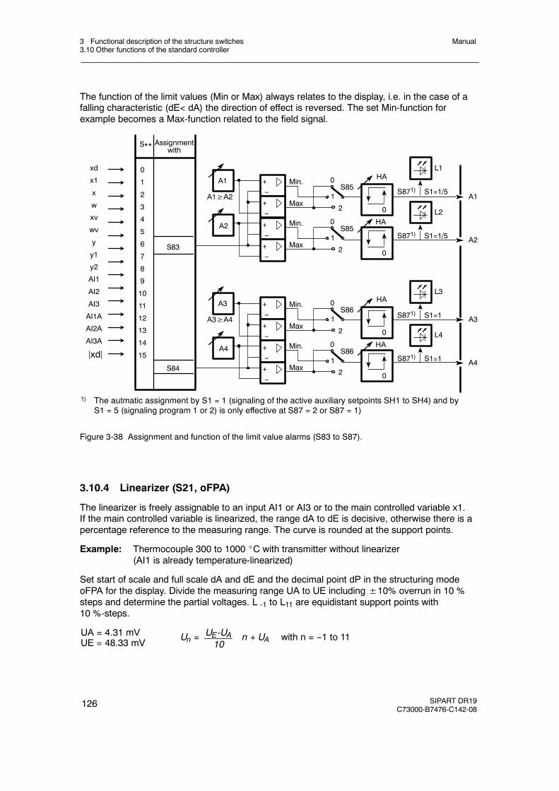
3 Functional description of the structure switches3.10 Other functions of the standard controller
Manual
126 SIPART DR19C73000-B7476-C142-08
The function of the limit values (Min or Max) always relates to the display, i.e. in the case of afalling characteristic (dE< dA) the direction of effect is reversed. The set Min-function forexample becomes a Max-function related to the field signal.
S84
S83
Assignmentwith
S**
xd
x1
x
w
xv
wv
y
y1
y2
AI1
AI2
AI3
AI1A
AI2A
AI3A
jxdj
0
1
2
3
4
5
6
7
8
9
10
11
12
13
14
15
A1 +--
Min.
+--
Max
S85
0
HA
A1
2
0
1
+--+-- 0
HA
A2
A2
A1≥A2
Min.
Max
S85
2
0
1
A3 +--
Min.
+--
Max
S86
0
HA
A3
2
0
1
+--+-- 0
HA
A4
A4
A3≥A4
Min.
Max
S86
2
0
1
S871) S1=1/5
L2
S871) S1=1/5
L1
S871) S1=1
L3
S871) S1=1
L4
1) The autmatic assignment by S1 = 1 (signaling of the active auxiliary setpoints SH1 to SH4) and byS1 = 5 (signaling program 1 or 2) is only effective at S87 = 2 or S87 = 1)
Figure 3-38 Assignment and function of the limit value alarms (S83 to S87).
3.10.4 Linearizer (S21, oFPA)
The linearizer is freely assignable to an input AI1 or AI3 or to the main controlled variable x1.If the main controlled variable is linearized, the range dA to dE is decisive, otherwise there is apercentage reference to the measuring range. The curve is rounded at the support points.
Example: Thermocouple 300 to 1000 _C with transmitter without linearizer(AI1 is already temperature-linearized)
Set start of scale and full scale dA and dE and the decimal point dP in the structuring modeoFPA for the display. Divide the measuring range UA to UE including±10% overrun in 10 %steps and determine the partial voltages. L -1 to L11 are equidistant support points with10 %-steps.
Un = n + UA with n = --1 to 11UE-UA10
UA = 4.31 mVUE = 48.33 mV
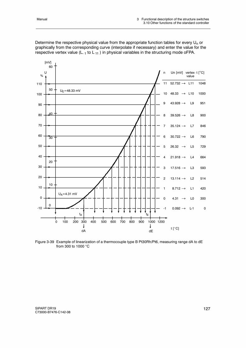
3 Functional description of the structure switches3.10 Other functions of the standard controller
Manual
SIPART DR19C73000-B7476-C142-08
127
Determine the respective physical value from the appropriate function tables for every Un orgraphically from the corresponding curve (interpolate if necessary) and enter the value for therespective vertex value (L- 1 to L 11 ) in physical variables in the structuring mode oFPA.
U
8 39.526 ! L8 900
7 35.124 ! L7 846
6 30.722 ! L6 790
5 26.32 ! L5 729
4 21.918 ! L4 664
3 17.516 ! L3 593
2 13.114 ! L2 514
1 8.712 ! L1 420
0 4.31 ! L0 300
-1 0.092 ! L-1 0
tA tE
UE=48.33 mV
60
50
40
30
20
10
0
0 100 200 300 400 500 600 700 800 900 1000 1200
110
100
90
80
70
60
50
40
30
20
10
0
-10
UA=4.31 mV
dA dEt [_C]
%n Un [mV] vertex- t [C]
value
11 52.732 ! L11 1048
10 48.33 ! L10 1000
9 43.928 ! L9 951
[mV]
Figure 3-39 Example of linearization of a thermocouple type B Pt30Rh/Pt6, measuring range dA to dEfrom 300 to 1000 C
3 Functional description of the structure switches3.10 Other functions of the standard controller
Manual
128 SIPART DR19C73000-B7476-C142-08
3.10.5 Restart conditions (S90, S91)
The restart conditions after mains recovery are determined with S90. With S90 = 0 the con-trollers restarts after mains recovery and after a watchdog reset with the oeprating mode andthe y which existed before the power failure. This variation must be used when temporarymains failures are to be expected in slow control circuits.
With S90 = 1 starting is effected after mains recovery in manual and internal mode with ys inthe K-controller (S2 = 0) and two-position controller (S2 = 1) or with the last y in the three-posi-tion controller (S2 = 2, 3). If only external operating mode has been selected by S43 = 1 or onlyautomatic mode by S52 = 1, restarting is effected in these modes.
With S91 the optical signaling of mains voltage recovery and reset is determined by flashing ofthe digital x display. The flashing is acknowledged by pressing the Shift key (6) or by an alarmrequest via SES.
3.10.6 Serial interface and PROFIBUS-DP (S92 to S99)
The structure switch S92 determines whether operation is with SES (S92 = 1/2/3*) or withoutSES (S92 = 0).
With S93 the depth of SES intervention is specified. Generally all available set data are read. Inposition 0 no transmission and reception of data to the controller is possible. In position 1 onlyparameters and structures can be transmitted. In positions 2 to 5 the process variables wES(external setpoint via the SES), wiES (internal setpoint via the SES), yES (external manipulatedvariable via the SES), yHES (manual manipulated variable via the SES) and all control signalscan be sent additionally via the SES. At the same time the sources for the external setpoint wESor wEA and the tracking manipulated variable yES or yN are switched with S93. This makes itpossible to preset the process variables and the control signals only via the SES or the processvariables analogly and only the control signals via the SES.
With S92 = 1/2/3 writing of the status signals SiES... to ...tSHES is locked optionally by RC orCB (see page 116).
The structure switches S94 to S99 determine the transmission procedure through the serialinterface. For further details, see the operating instructions “Serial SIPART DR190x Bus Inter-face”, Internet address www.fielddevices.com [Edition 05.2000].
Settings for PROFIBUS-DP see table 5-5, page 190 (structure switch list).
1) as of software version --C4
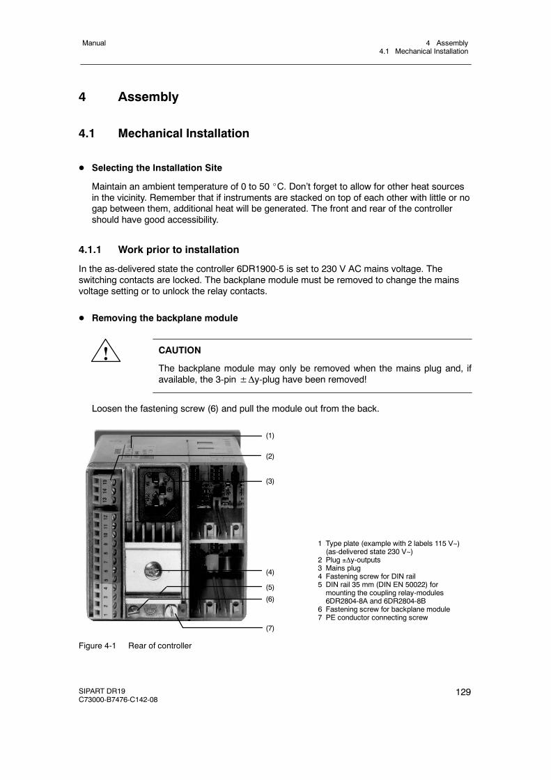
4 Assembly4.1 Mechanical Installation
Manual
SIPART DR19C73000-B7476-C142-08
129
4 Assembly
4.1 Mechanical Installation
D Selecting the Installation Site
Maintain an ambient temperature of 0 to 50 _C. Don’t forget to allow for other heat sourcesin the vicinity. Remember that if instruments are stacked on top of each other with little or nogap between them, additional heat will be generated. The front and rear of the controllershould have good accessibility.
4.1.1 Work prior to installation
In the as-delivered state the controller 6DR1900-5 is set to 230 V AC mains voltage. Theswitching contacts are locked. The backplane module must be removed to change the mainsvoltage setting or to unlock the relay contacts.
D Removing the backplane module
! CAUTION
The backplane module may only be removed when the mains plug and, ifavailable, the 3-pin±Δy-plug have been removed!
Loosen the fastening screw (6) and pull the module out from the back.
1 Type plate (example with 2 labels 115 V~)(as-delivered state 230 V~)
2 Plug y-outputs3 Mains plug4 Fastening screw for DIN rail5 DIN rail 35 mm (DIN EN 50022) formounting the coupling relay-modules6DR2804-8A and 6DR2804-8B
6 Fastening screw for backplane module7 PE conductor connecting screw
(1)
(2)
(7)
(4)
(5)
(6)
(3)
Figure 4-1 Rear of controller
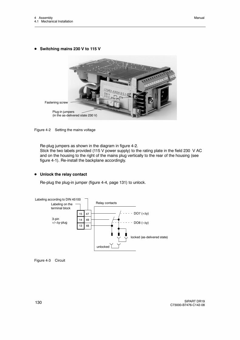
4 Assembly4.1 Mechanical Installation
Manual
130 SIPART DR19C73000-B7476-C142-08
D Switching mains 230 V to 115 V
Fastening screw
Plug-in jumpers(in the as-delivered state 230 V)
Figure 4-2 Setting the mains voltage
Re-plug jumpers as shown in the diagram in figure 4-2.Stick the two labels provided (115 V power supply) to the rating plate in the field 230 V ACand on the housing to the right of the mains plug vertically to the rear of the housing (seefigure 4-1). Re-install the backplane accordingly.
D Unlock the relay contact
Re-plug the plug-in jumper (figure 4-4, page 131) to unlock.
Labeling according to DIN 45100Labeling on theterminal block
15 47
14 49
13 48
3-pin+/--y-plug
Relay contacts
DO7 (+y)
DO8 (--y)
locked (as-delivered state)
unlocked
Figure 4-3 Circuit
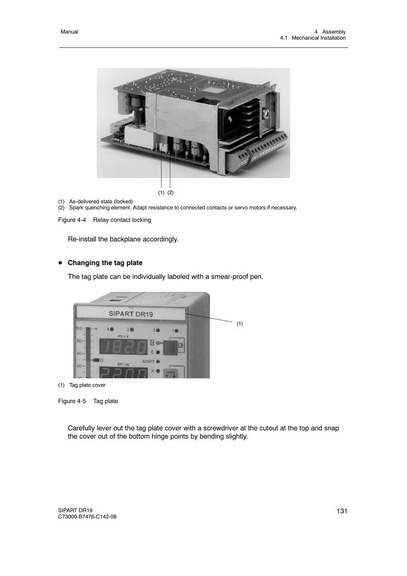
4 Assembly4.1 Mechanical Installation
Manual
SIPART DR19C73000-B7476-C142-08
131
(1) (2)
(1) As-delivered state (locked)(2) Spark quenching element. Adapt resistance to connected contacts or servo motors if necessary.
Figure 4-4 Relay contact locking
Re-install the backplane accordingly.
D Changing the tag plate
The tag plate can be individually labeled with a smear-proof pen.
(1)
(1) Tag plate cover
Figure 4-5 Tag plate
Carefully lever out the tag plate cover with a screwdriver at the cutout at the top and snapthe cover out of the bottom hinge points by bending slightly.
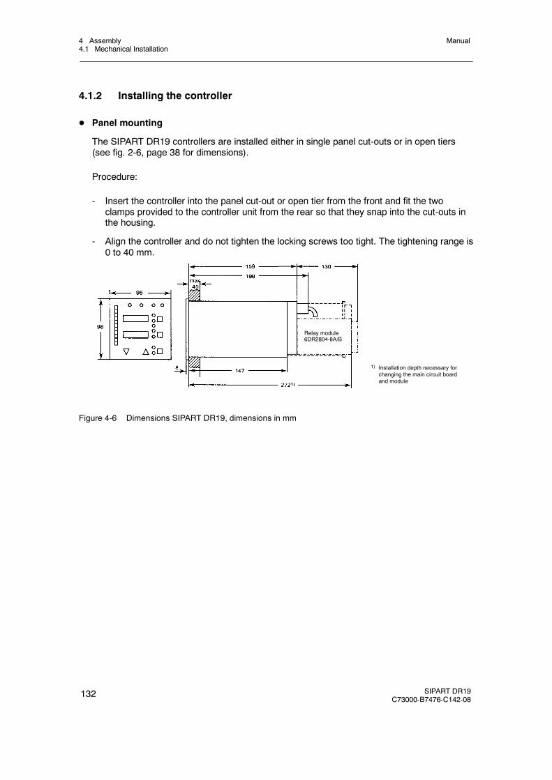
4 Assembly4.1 Mechanical Installation
Manual
132 SIPART DR19C73000-B7476-C142-08
4.1.2 Installing the controller
D Panel mounting
The SIPART DR19 controllers are installed either in single panel cut-outs or in open tiers(see fig. 2-6, page 38 for dimensions).
Procedure:
- Insert the controller into the panel cut-out or open tier from the front and fit the twoclamps provided to the controller unit from the rear so that they snap into the cut-outs inthe housing.
- Align the controller and do not tighten the locking screws too tight. The tightening range is0 to 40 mm.
1) Installation depth necessary forchanging the main circuit boardand module
Relay module6DR2804-8A/B
Figure 4-6 Dimensions SIPART DR19, dimensions in mm
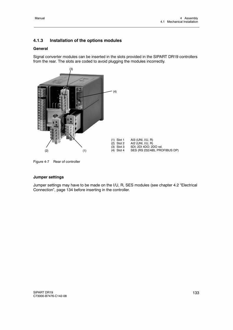
4 Assembly4.1 Mechanical Installation
Manual
SIPART DR19C73000-B7476-C142-08
133
4.1.3 Installation of the options modules
General
Signal converter modules can be inserted in the slots provided in the SIPART DR19 controllersfrom the rear. The slots are coded to avoid plugging the modules incorrectly.
(1) Slot 1 AI3 (UNI, I/U, R)(2) Slot 2 AI2 (UNI, I/U, R)(3) Slot 3 5DI; 2DI 4DO; 2DO rel.(4) Slot 4 SES (RS 232/485, PROFIBUS DP)(2)
(3)
(4)
(1)
Figure 4-7 Rear of controller
Jumper settings
Jumper settings may have to be made on the I/U, R, SES modules (see chapter 4.2 “ElectricalConnection”, page 134 before inserting in the controller.
4 Assembly4.2 Electrical Connection
Manual
134 SIPART DR19C73000-B7476-C142-08
4.2 Electrical Connection
4.2.1 Warnings and block diagram
The arrangement of the connecting elements can be seen in fig. 4-7, page 133.
! WARNING
The “Regulations for the installation of power systems with rated voltagesunder 1000 V” (VDE 0100)” must be observed in the electrical installation!
D PE conductor connection
Connect the PE conductor to the ground screw (see figure 4-8), page 136 on the back of thecontroller. When connecting to 115 V or 230 V AC-mains the PE conductor connection canalso be fed via the three-pin plug (see figure 4-9, page 137). The controller’s ground-connec-tion may also be connected with the PE conductor (grounded extra low voltages).
! WARNING
Disconnection of thePEconductor while the controller is poweredup canmakethe controller potentially dangerous. Disconnection of the PE conductor isprohibited.
D Power supply connection
The power supply is connected for 115 V AC or 230 V AC by a three-pin plug IEC 320/VDIN 49457 A, at 24 V UC the power supply iy connected by a special 2-pin plug (any polar-ity). The mains plugs are part of the scope of delivery.
! WARNING
Set the mains voltage plug-in jumpers (see figure 4-2), page 130 in the no-voltage state to the existing mains voltage.It is essential to observe the mains voltage specified on the rating plate or bythe mains voltage jumpers (115/230 V AC) or on the voltage plate (24 V UC)!Lay the power cable through a fuse; limit the rating (fire protection EN61010-1)to≤ 150 VA. Limit the mains voltage alternatively to 30 V at 24 V UC.
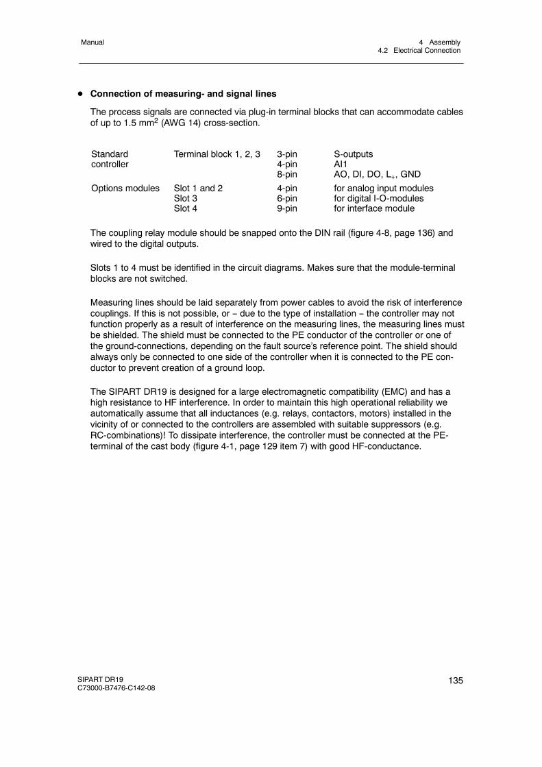
4 Assembly4.2 Electrical Connection
Manual
SIPART DR19C73000-B7476-C142-08
135
D Connection of measuring- and signal lines
The process signals are connected via plug-in terminal blocks that can accommodate cablesof up to 1.5 mm2 (AWG 14) cross-section.
Standardcontroller
Terminal block 1, 2, 3 3-pin4-pin8-pin
S-outputsAI1AO, DI, DO, L+, GND
Options modules Slot 1 and 2Slot 3Slot 4
4-pin6-pin9-pin
for analog input modulesfor digital I-O-modulesfor interface module
The coupling relay module should be snapped onto the DIN rail (figure 4-8, page 136) andwired to the digital outputs.
Slots 1 to 4 must be identified in the circuit diagrams. Makes sure that the module-terminalblocks are not switched.
Measuring lines should be laid separately from power cables to avoid the risk of interferencecouplings. If this is not possible, or -- due to the type of installation -- the controller may notfunction properly as a result of interference on the measuring lines, the measuring lines mustbe shielded. The shield must be connected to the PE conductor of the controller or one ofthe ground-connections, depending on the fault source’s reference point. The shield shouldalways only be connected to one side of the controller when it is connected to the PE con-ductor to prevent creation of a ground loop.
The SIPART DR19 is designed for a large electromagnetic compatibility (EMC) and has ahigh resistance to HF interference. In order to maintain this high operational reliability weautomatically assume that all inductances (e.g. relays, contactors, motors) installed in thevicinity of or connected to the controllers are assembled with suitable suppressors (e.g.RC-combinations)! To dissipate interference, the controller must be connected at the PE-terminal of the cast body (figure 4-1, page 129 item 7) with good HF-conductance.
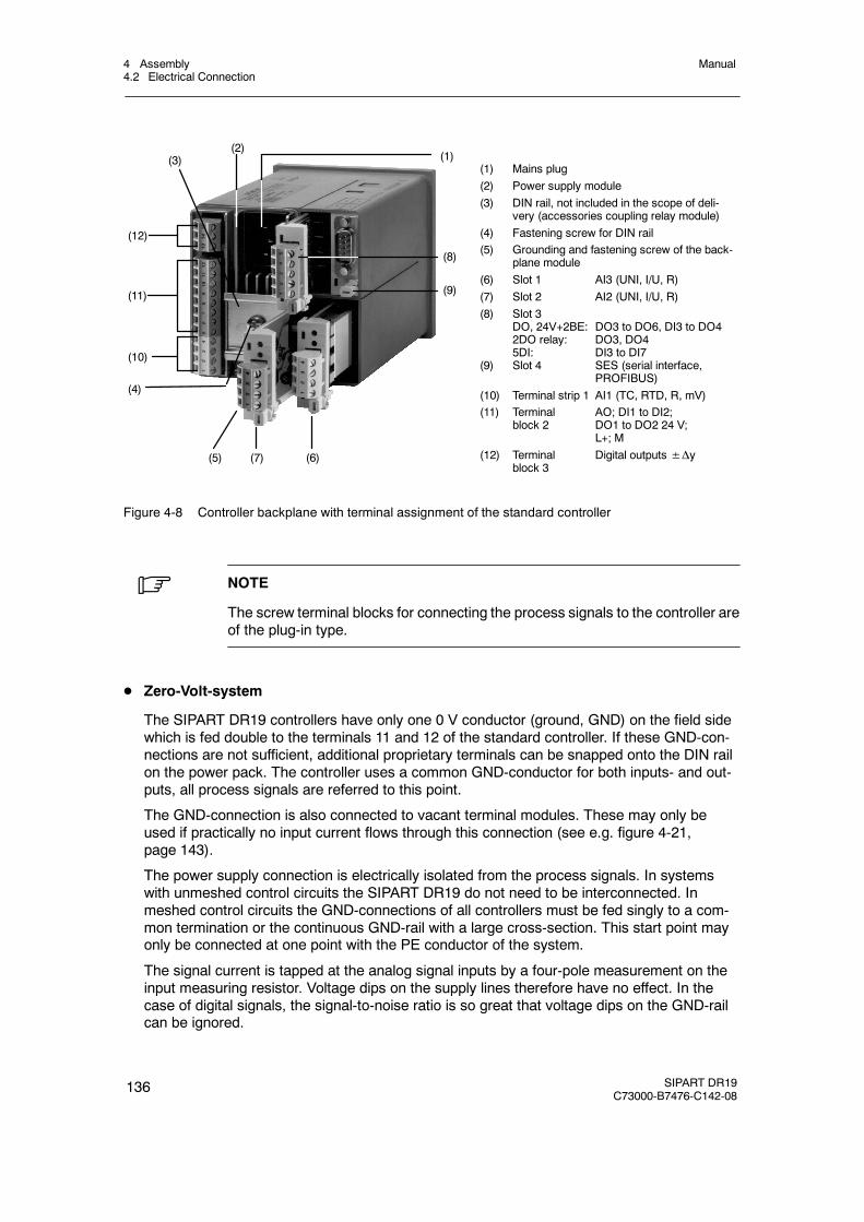
4 Assembly4.2 Electrical Connection
Manual
136 SIPART DR19C73000-B7476-C142-08
(1) Mains plug(2) Power supply module(3) DIN rail, not included in the scope of deli-
very (accessories coupling relay module)(4) Fastening screw for DIN rail(5) Grounding and fastening screw of the back-
plane module(6) Slot 1 AI3 (UNI, I/U, R)(7) Slot 2 AI2 (UNI, I/U, R)(8) Slot 3
DO, 24V+2BE: DO3 to DO6, DI3 to DO42DO relay: DO3, DO45DI: DI3 to DI7
(9) Slot 4 SES (serial interface,PROFIBUS)
(10) Terminal strip 1 AI1 (TC, RTD, R, mV)(11) Terminal AO; DI1 to DI2;
block 2 DO1 to DO2 24 V;L+; M
(12) Terminal Digital outputs±Δyblock 3
(6)
(4)
(10)
(8)
(11)
(12)
(2)(1)
(7)(5)
(9)
(3)
Figure 4-8 Controller backplane with terminal assignment of the standard controller
. NOTE
The screw terminal blocks for connecting the process signals to the controller areof the plug-in type.
D Zero-Volt-system
The SIPART DR19 controllers have only one 0 V conductor (ground, GND) on the field sidewhich is fed double to the terminals 11 and 12 of the standard controller. If these GND-con-nections are not sufficient, additional proprietary terminals can be snapped onto the DIN railon the power pack. The controller uses a common GND-conductor for both inputs- and out-puts, all process signals are referred to this point.
The GND-connection is also connected to vacant terminal modules. These may only beused if practically no input current flows through this connection (see e.g. figure 4-21,page 143).
The power supply connection is electrically isolated from the process signals. In systemswith unmeshed control circuits the SIPART DR19 do not need to be interconnected. Inmeshed control circuits the GND-connections of all controllers must be fed singly to a com-mon termination or the continuous GND-rail with a large cross-section. This start point mayonly be connected at one point with the PE conductor of the system.
The signal current is tapped at the analog signal inputs by a four-pole measurement on theinput measuring resistor. Voltage dips on the supply lines therefore have no effect. In thecase of digital signals, the signal-to-noise ratio is so great that voltage dips on the GND-railcan be ignored.
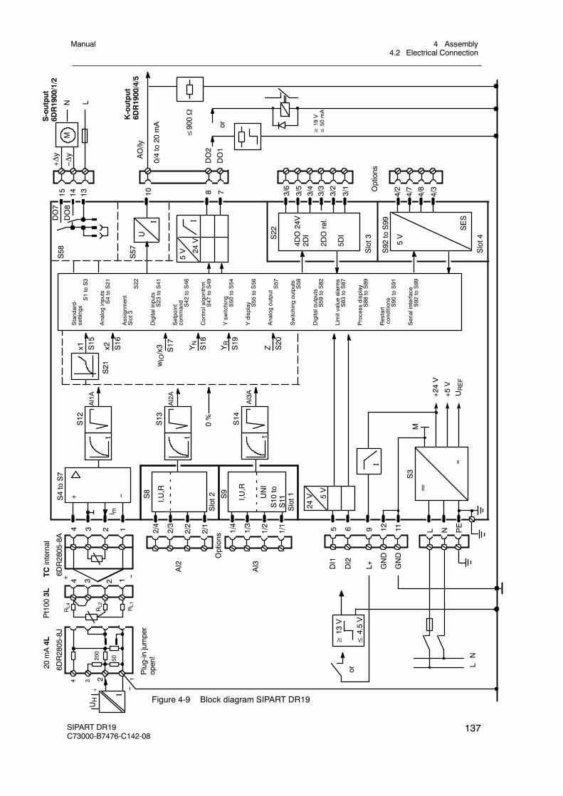
10
AI3A
S13
AI2A
≤900Ω
S12
AI1A
S8
4 3 2 1
6DR2805-8A
TCinternal
Pt100
3L
+ --
i m
RL2
RL4 RL1
20mA4L
4 3 2 1
200
50
UH
I
+ --
Plug-injumper
open!
6DR2805-8J
≥13
V
≤4.5V
or
AI2
Slot2 S9
Slot1I,U
,R
I,U,R
AI3
Options
UNI
S10
toS11
0%
YN
S18
5 6 12 11
DI1
DI2
24V 5V
9L+ GND
GND
LN
M
+24V
+5V
UREF
S14
S21
24V
5V
I
U
I
S57
15 14 13 8 7
S22
Z S20
YR
S19
wIO/x3 S17x2 S16
x1 S15
4DO24V
2DI
2DOrel.
5DI
Slot3
S92
toS99
4/2
4/7
4/8
4/3
Slot4
SES
5V
MN L
DO2
DO1
+Δy
--Δy AO/ly
0/4to20
mA or
≥19
V≤
50mA
IOptions
Standard-
settings
S1toS3
Analoginputs
S4toS21
Assignm
ent
Slot3
S22
Digitalinputs
S23
toS41
Setpoint
command
S42
toS46
Controlalgorithm
S47
toS49
Ysw
itching
S50
toS54
Ydisplay S55
toS56
AnalogoutputS57
Switching
outputs
S58
Digitaloutputs
S59
toS82
Limitvaluealarms
S83
toS87
Process
display
S88
toS89
Restart
conditions
S90
toS91
Serialinterface
S92
toS99
S4toS7
+ --
S3
=
S-output
6DR1900/1/2
K-output
6DR1900/4/5
1/4
1/3
1/2
1/1
N PE
L2/4
2/3
2/2
2/1
3/6
3/5
3/4
3/3
3/2
3/1
S58
4 3 2 1
DO7
DO8
ttt
Figure 4-9 Block diagram SIPART DR19
4 Assembly4.2 Electrical Connection
Manual
SIPART DR19C73000-B7476-C142-08
137
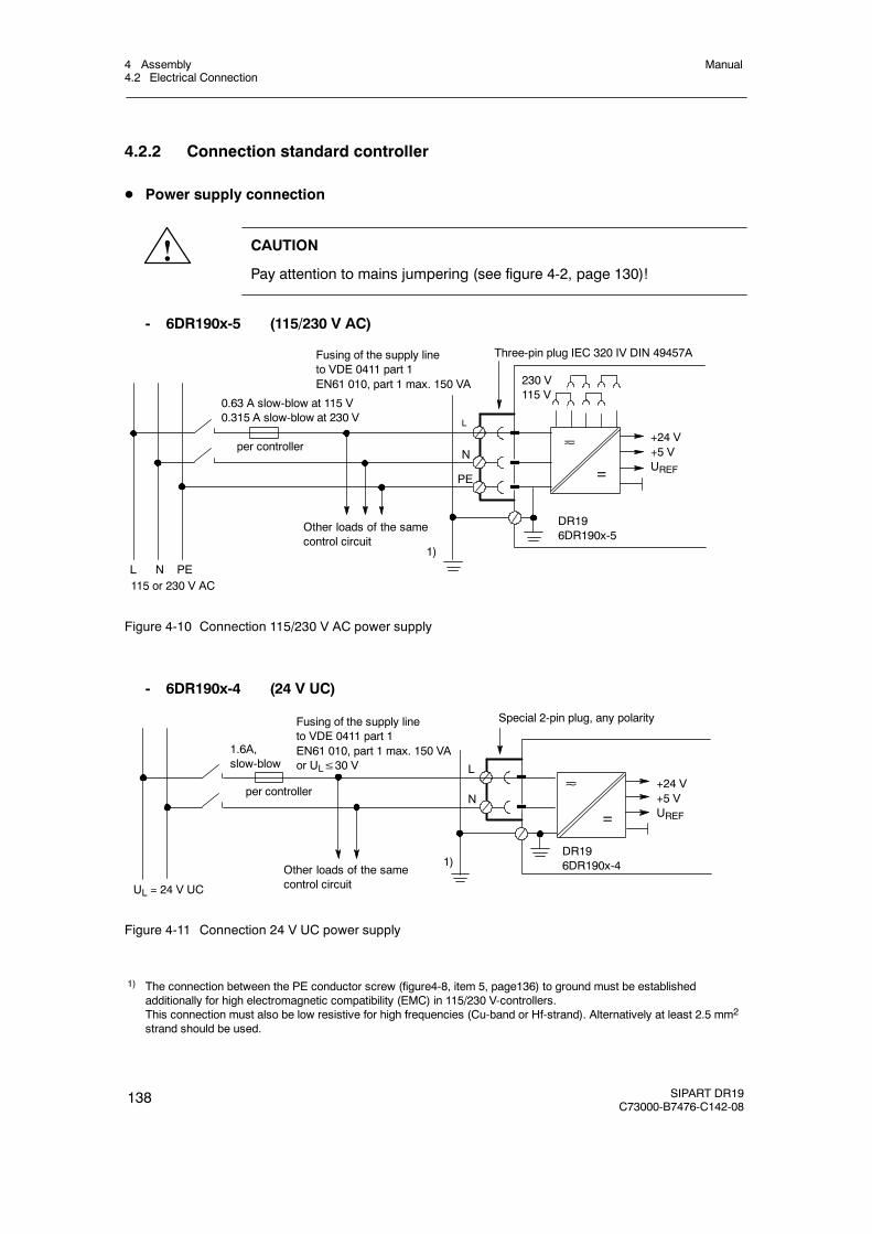
4 Assembly4.2 Electrical Connection
Manual
138 SIPART DR19C73000-B7476-C142-08
4.2.2 Connection standard controller
D Power supply connection
! CAUTION
Pay attention to mains jumpering (see figure 4-2, page 130)!
- 6DR190x-5 (115/230 V AC)
=
+24 V+5 VUREF
0.63 A slow-blow at 115 V0.315 A slow-blow at 230 V
per controller
1)
L
N
Three-pin plug IEC 320 IV DIN 49457A
230 V115 V
PE
L N PE115 or 230 V AC
DR196DR190x-5
Fusing of the supply lineto VDE 0411 part 1EN61 010, part 1 max. 150 VA
Other loads of the samecontrol circuit
Figure 4-10 Connection 115/230 V AC power supply
- 6DR190x-4 (24 V UC)
=
1.6A,slow-blow
per controller
1)
L
N
Special 2-pin plug, any polarity
UL = 24 V UC
+24 V+5 VUREF
Fusing of the supply lineto VDE 0411 part 1EN61 010, part 1 max. 150 VAor UL≤30 V
Other loads of the samecontrol circuit
DR196DR190x-4
Figure 4-11 Connection 24 V UC power supply
1) The connection between the PE conductor screw (figure4-8, item 5, page136) to ground must be establishedadditionally for high electromagnetic compatibility (EMC) in 115/230 V-controllers.This connection must also be low resistive for high frequencies (Cu-band or Hf-strand). Alternatively at least 2.5 mm2
strand should be used.
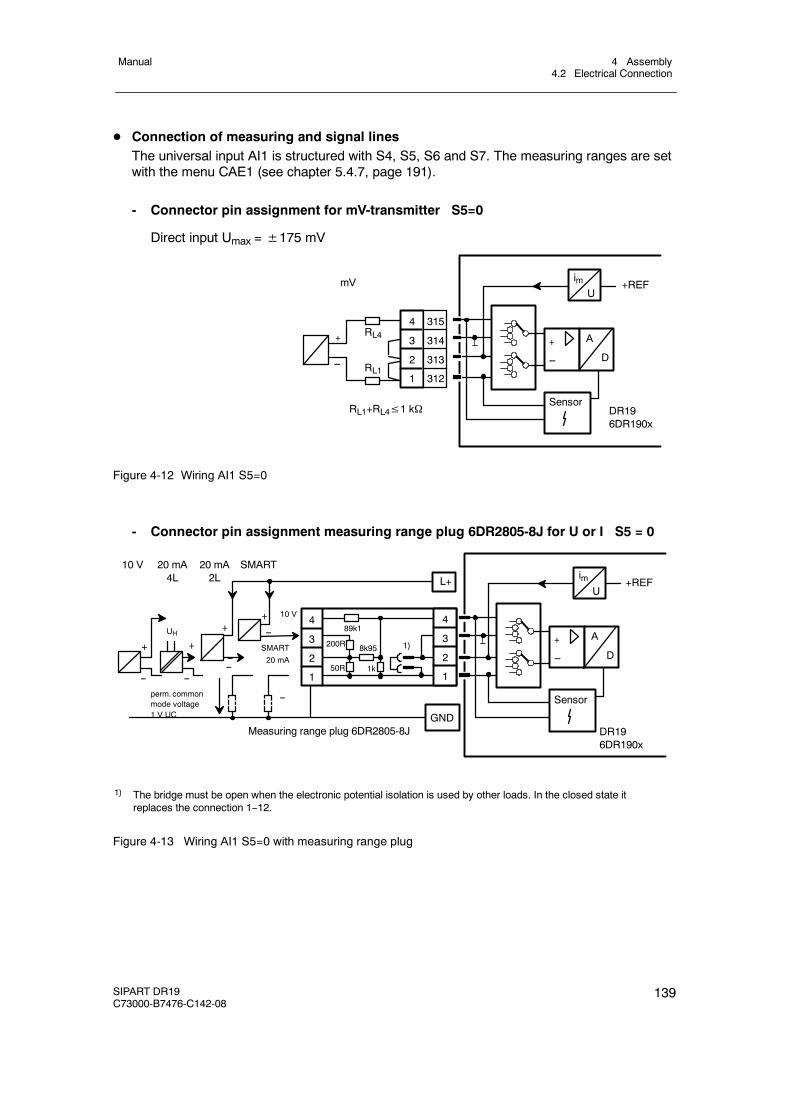
4 Assembly4.2 Electrical Connection
Manual
SIPART DR19C73000-B7476-C142-08
139
D Connection of measuring and signal linesThe universal input AI1 is structured with S4, S5, S6 and S7. The measuring ranges are setwith the menu CAE1 (see chapter 5.4.7, page 191).
- Connector pin assignment for mV-transmitter S5=0
Direct input Umax =±175 mV
RL4
RL1
RL1+RL4≤1 kΩ
+
--
mV imU
+REF
+
--
A
D
SensorDR196DR190x
4
3
2
1
315
314
313
312
Figure 4-12 Wiring AI1 S5=0
- Connector pin assignment measuring range plug 6DR2805-8J for U or I S5 = 0
4
3
2
1
89k1
200R 8k95
50R 1k
10 V+
--SMART
20 mA
+
--perm. commonmode voltage1 V UC
UH
+
--
Measuring range plug 6DR2805-8J
imU
+REF
+
--
A
D
Sensor
4
3
2
1
+
--
10 V 20 mA4L
20 mA2L
SMART
--
L+
GND
1) The bridge must be open when the electronic potential isolation is used by other loads. In the closed state itreplaces the connection 1--12.
1)
DR196DR190x
--
Figure 4-13 Wiring AI1 S5=0 with measuring range plug
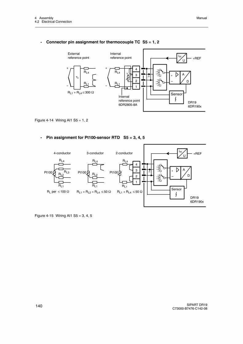
4 Assembly4.2 Electrical Connection
Manual
140 SIPART DR19C73000-B7476-C142-08
- Connector pin assignment for thermocouple TC S5 = 1, 2
imU
+REF
+
--
A
D
Sensor
4
3
2
1
RL4
RL1 + RL4≤300 Ω
T
RL1
Internalreference point6DR2805-8A
Internalreference point
+
--
RL4
RL1
+
--
Tb
Externalreference point
DR196DR190x
Figure 4-14 Wiring AI1 S5 = 1, 2
- Pin assignment for Pt100-sensor RTD S5 = 3, 4, 5
RL per≤100 Ω
RL4
Pt100
4-conductor
RL1
2-conductor
RL4
Pt100
RL1
RL2
3-conductor
RL4
Pt100
RL1
RL2RL3
RL1 = RL2 = RL4≤50 Ω RL1 + RL4≤50 Ω
imU
+REF
+
--
A
D
Sensor
4
3
2
1
DR196DR190x
Figure 4-15 Wiring AI1 S5 = 3, 4, 5
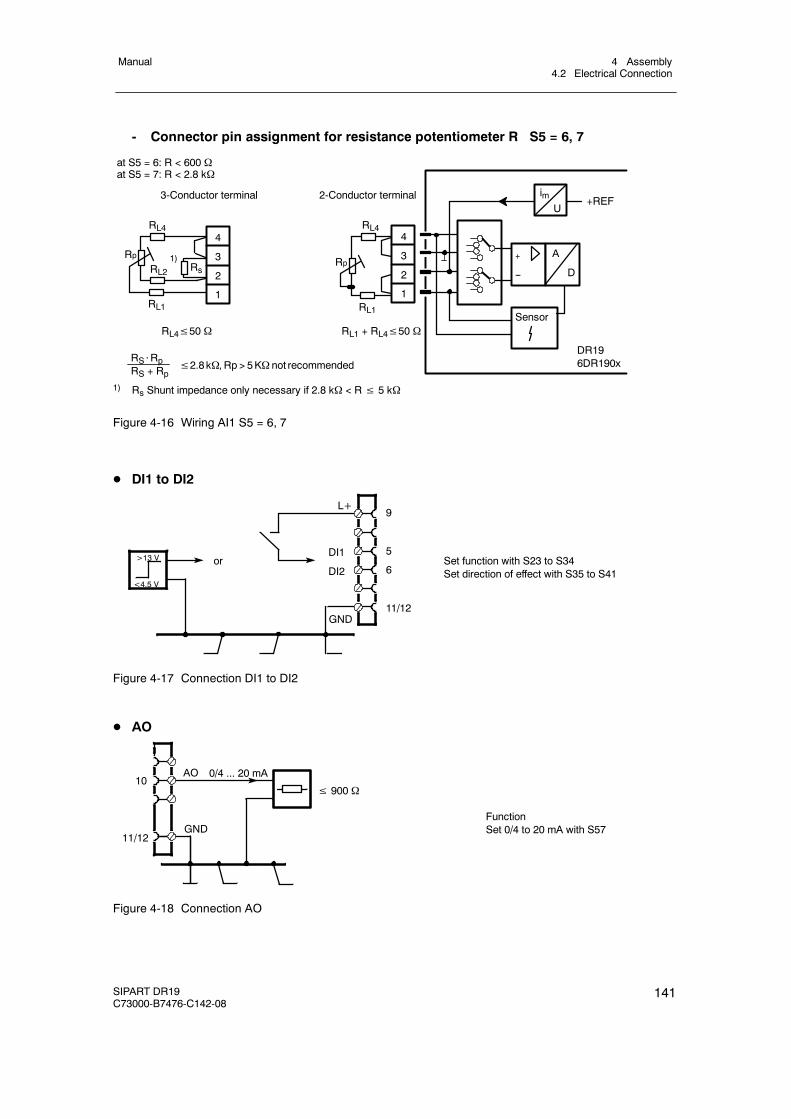
4 Assembly4.2 Electrical Connection
Manual
SIPART DR19C73000-B7476-C142-08
141
- Connector pin assignment for resistance potentiometer R S5 = 6, 7
2-Conductor terminal3-Conductor terminal
RL4
Rp
RL1
RL4
Rp
RL1
RL21)
Rs
RL4≤50 Ω RL1 + RL4≤50 Ω
RS⋅RpRS + Rp
≤2.8kΩ, Rp > 5KΩ not recommended
imU
+REF
+
--
A
D
Sensor
4
3
2
1
4
3
2
1
at S5 = 6: R < 600 Ωat S5 = 7: R < 2.8 kΩ
DR196DR190x
1) Rs Shunt impedance only necessary if 2.8 kΩ < R≤ 5 kΩ
Figure 4-16 Wiring AI1 S5 = 6, 7
D DI1 to DI2
<4.5 V
>13 V or
9
5
6
11/12
DI1
DI2
L+
GND
Set function with S23 to S34Set direction of effect with S35 to S41
Figure 4-17 Connection DI1 to DI2
D AO
≤ 900 Ω
0/4 ... 20 mA10
11/12GND
FunctionSet 0/4 to 20 mA with S57
AO
Figure 4-18 Connection AO
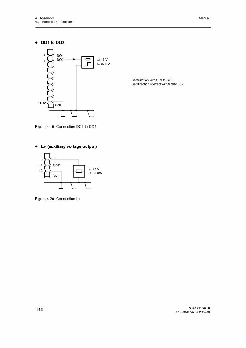
4 Assembly4.2 Electrical Connection
Manual
142 SIPART DR19C73000-B7476-C142-08
D DO1 to DO2
DO1DO2
7
8≥ 19 V≤ 50 mA
GND
Set function with S59 to S75Set direction of effect with S76 toS82
11/12
Figure 4-19 Connection DO1 to DO2
D L+ (auxiliary voltage output)
≥ 20 V≤ 60 mA
L+9
11
12
GND
GND
Figure 4-20 Connection L+
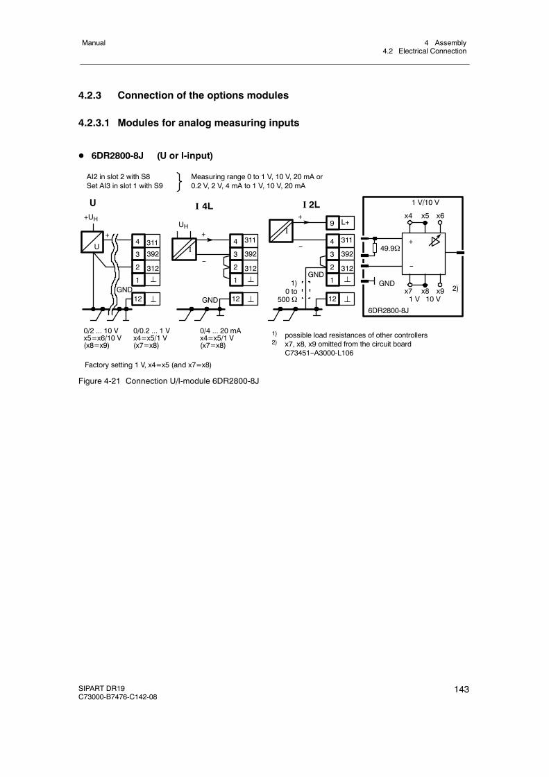
4 Assembly4.2 Electrical Connection
Manual
SIPART DR19C73000-B7476-C142-08
143
4.2.3 Connection of the options modules
4.2.3.1 Modules for analog measuring inputs
D 6DR2800-8J (U or I-input)
+
GND
UH
I 4L+UH
U
+
0/2 ... 10 V 0/0.2 ... 1 Vx5=x6/10 V x4=x5/1 V(x8=x9) (x7=x8)
I
0/4 ... 20 mAx4=x5/1 V(x7=x8)
U
Factory setting 1 V, x4=x5 (and x7=x8)
AI2 in slot 2 with S8 Measuring range 0 to 1 V, 10 V, 20 mA orSet AI3 in slot 1 with S9 0.2 V, 2 V, 4 mA to 1 V, 10 V, 20 mA
3114
3923
3122
1
12
3114
3923
3122
1
12
--
+
I
1) possible load resistances of other controllers2) x7, x8, x9 omitted from the circuit board
C73451--A3000-L106
3114
3923
3122
1
12
--
L+9
1)0 to
500 Ω
1 V/10 V
49.9Ω+
--
x4 x5 x6
x7 x8 x9 2)1 V 10 V
6DR2800-8J
I 2L
GNDGND
GND
Figure 4-21 Connection U/I-module 6DR2800-8J
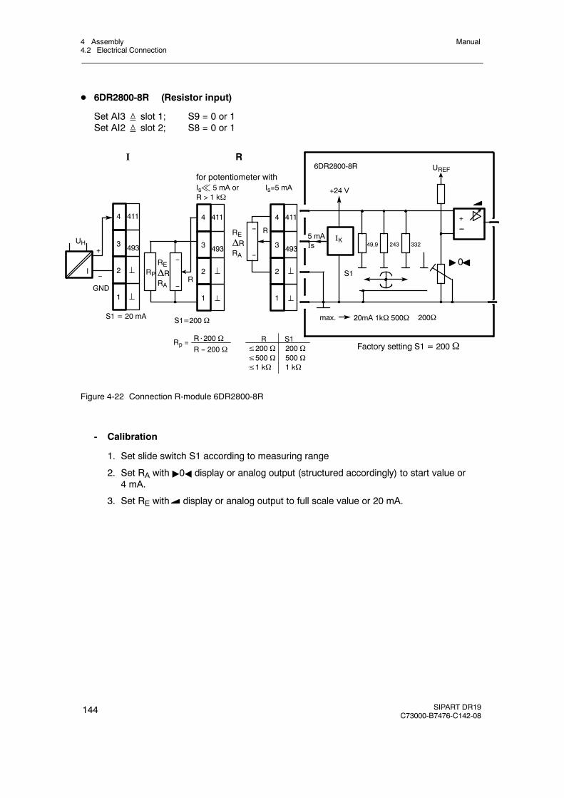
4 Assembly4.2 Electrical Connection
Manual
144 SIPART DR19C73000-B7476-C142-08
D 6DR2800-8R (Resistor input)
Set AI3≙ slot 1; S9 = 0 or 1Set AI2≙ slot 2; S8 = 0 or 1
R S1≤200 Ω 200 Ω≤500 Ω 500 Ω≤1 kΩ 1 kΩ
max.
UREF
20mA 1kΩ 500Ω
49,9 243 3325 mAIs
IKR
0
+24 V
S1R
REΔRRA
+
6DR2800-8Rfor potentiometer withIs% 5 mA or Is=5 mAR > 1 kΩ
I R
Factory setting S1 = 200Ω
S1 = 20 mA
R⋅200 ΩR -- 200 Ω
Rp =
4114
4933
2
1
4114
4933
2
1
S1=200 Ω
I
REΔRRA
4114
4933
2
1
+--
UH
RP--
--
--
--
--
200Ω
GND
Figure 4-22 Connection R-module 6DR2800-8R
- Calibration
1. Set slide switch S1 according to measuring range
2. Set RA with "0A display or analog output (structured accordingly) to start value or4 mA.
3. Set RE with display or analog output to full scale value or 20 mA.
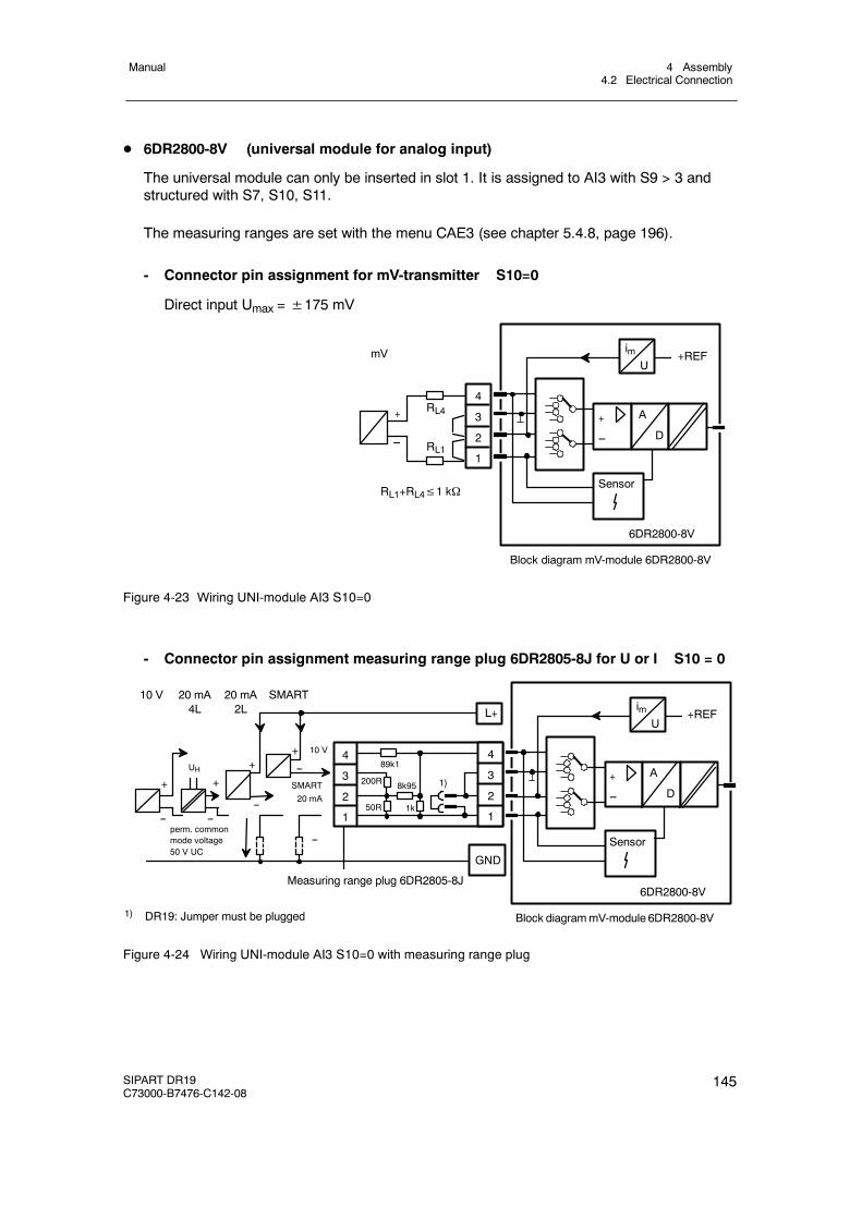
4 Assembly4.2 Electrical Connection
Manual
SIPART DR19C73000-B7476-C142-08
145
D 6DR2800-8V (universal module for analog input)
The universal module can only be inserted in slot 1. It is assigned to AI3 with S9 > 3 andstructured with S7, S10, S11.
The measuring ranges are set with the menu CAE3 (see chapter 5.4.8, page 196).
- Connector pin assignment for mV-transmitter S10=0
Direct input Umax =±175 mV
RL4
RL1
RL1+RL4≤1 kΩ
+
--
mV
Block diagram mV-module 6DR2800-8V
imU
+REF
+
--
A
D
Sensor
6DR2800-8V
4
3
2
1
Figure 4-23 Wiring UNI-module AI3 S10=0
- Connector pin assignment measuring range plug 6DR2805-8J for U or I S10 = 0
4
3
2
1
89k1
200R 8k95
50R 1k
10 V+
--SMART
20 mA
+
--perm. commonmode voltage50 V UC
UH
+
--
Measuring range plug 6DR2805-8J
Block diagrammV-module 6DR2800-8V
imU
+REF
+
--
A
D
Sensor
6DR2800-8V
4
3
2
1
+
10 V 20 mA4L
20 mA2L
SMART
--
L+
GND
1) DR19: Jumper must be plugged
1)
--
Figure 4-24 Wiring UNI-module AI3 S10=0 with measuring range plug
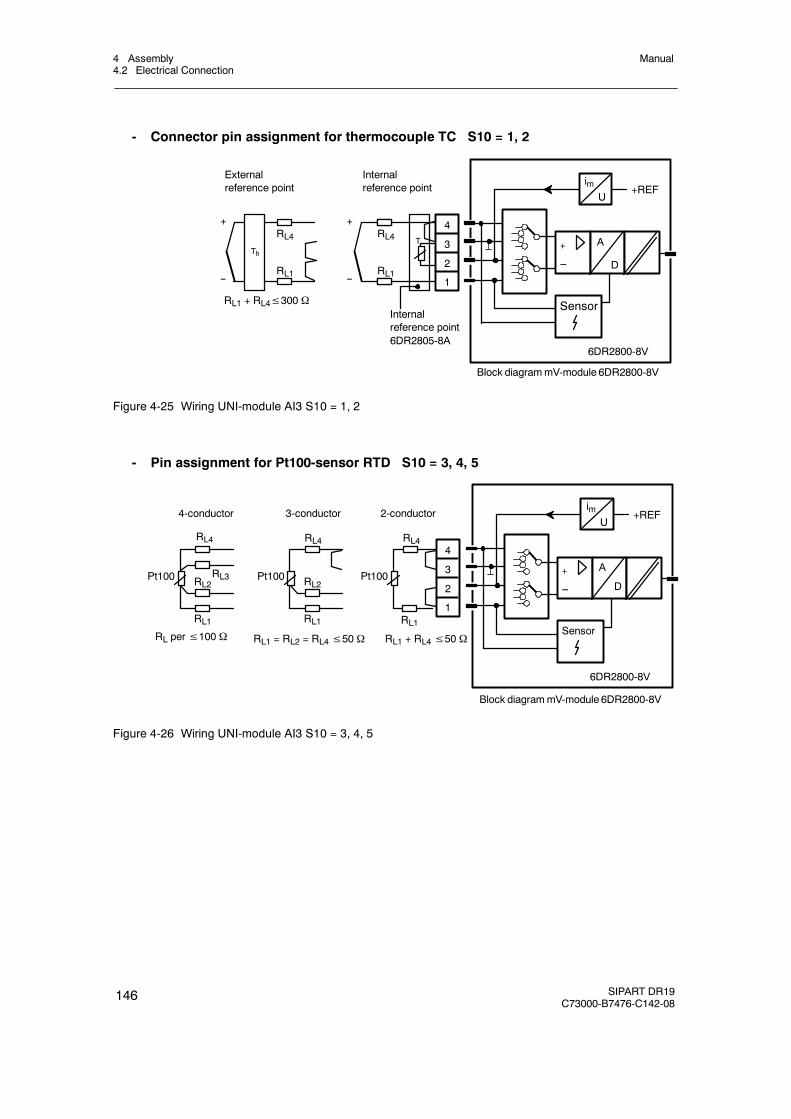
4 Assembly4.2 Electrical Connection
Manual
146 SIPART DR19C73000-B7476-C142-08
- Connector pin assignment for thermocouple TC S10 = 1, 2
imU
+REF
+
--
A
D
Sensor
6DR2800-8V
4
3
2
1
RL4
RL1 + RL4≤300 Ω
T
RL1
Internalreference point6DR2805-8A
Internalreference point
+
--
RL4
RL1
+
--
Tb
Externalreference point
Block diagrammV-module 6DR2800-8V
Figure 4-25 Wiring UNI-module AI3 S10 = 1, 2
- Pin assignment for Pt100-sensor RTD S10 = 3, 4, 5
RL per≤100 Ω
RL4
Pt100
4-conductor
RL1
2-conductor
RL4
Pt100
RL1
RL2
3-conductor
RL4
Pt100
RL1
RL2RL3
RL1 = RL2 = RL4≤50 Ω RL1 + RL4≤50 Ω
Block diagrammV-module 6DR2800-8V
imU
+REF
+
--
A
D
Sensor
6DR2800-8V
4
3
2
1
Figure 4-26 Wiring UNI-module AI3 S10 = 3, 4, 5
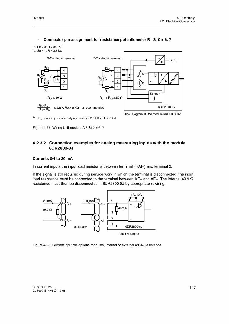
4 Assembly4.2 Electrical Connection
Manual
SIPART DR19C73000-B7476-C142-08
147
- Connector pin assignment for resistance potentiometer R S10 = 6, 7
2-Conductor terminal3-Conductor terminal
Block diagram of UNI-module 6DR2800-8V
RL4
Rp
RL1
RL4
Rp
RL1
RL21)
Rs
RL4≤50 Ω RL1 + RL4≤50 Ω
RS⋅RpRS + Rp
≤2.8 k, Rp > 5 KΩ not recommended
imU
+REF
+
--
A
D
Sensor
6DR2800-8V
4
3
2
1
4
3
2
1
at S8 = 6: R < 600 Ωat S8 = 7: R < 2.8 kΩ
1) Rs Shunt impedance only necessary if 2.8 kΩ < R≤ 5 kΩ
Figure 4-27 Wiring UNI-module AI3 S10 = 6, 7
4.2.3.2 Connection examples for analog measuring inputs with the module6DR2800-8J
Currents 0/4 to 20 mA
In current inputs the input load resistor is between terminal 4 (AI+) and terminal 3.
If the signal is still required during service work in which the terminal is disconnected, the inputload resistance must be connected to the terminal between AE+ and AE--. The internal 49.9 Ωresistance must then be disconnected in 6DR2800-8J by appropriate rewiring.
AI+
AI -
20 mA
49.9 Ω
1 V/10 V
--
+49.9 Ω
optionally 6DR2800-8J
AI+
AI -
20 mA 4
3
2
1
set 1 V jumper
Figure 4-28 Current input via options modules, internal or external 49.9Ω resistance
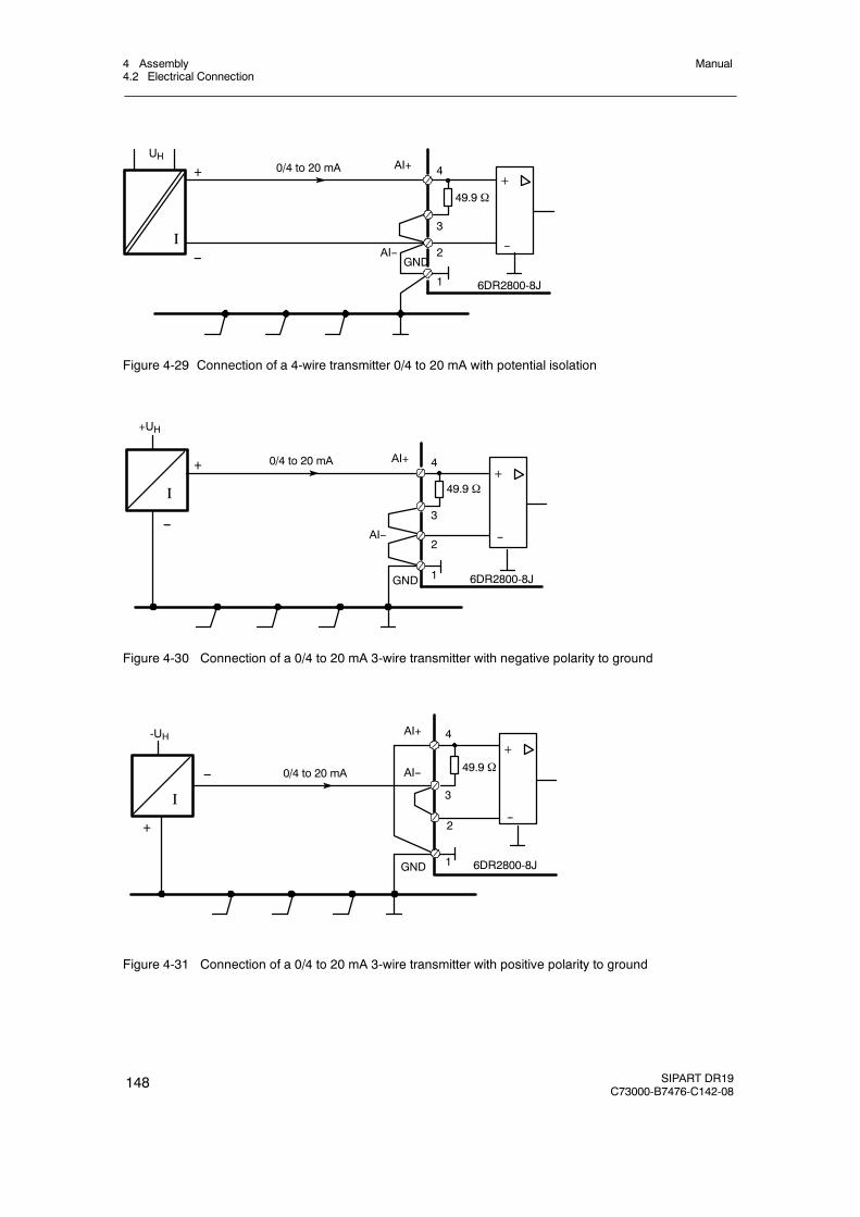
4 Assembly4.2 Electrical Connection
Manual
148 SIPART DR19C73000-B7476-C142-08
I
0/4 to 20 mA+
UHAI+
AI--GND
--
49.9 Ω
6DR2800-8J1
2
3
4
--
+
Figure 4-29 Connection of a 4-wire transmitter 0/4 to 20 mA with potential isolation
0/4 to 20 mA
+UH
AI+
AI--
GND 6DR2800-8J1
2
3
4+
--
49.9 ΩI
--
+
Figure 4-30 Connection of a 0/4 to 20 mA 3-wire transmitter with negative polarity to ground
0/4 to 20 mA
-UH AI+
AI--
GND 1
2
4+
--
49.9 Ω
3
6DR2800-8J
I
--
+
Figure 4-31 Connection of a 0/4 to 20 mA 3-wire transmitter with positive polarity to ground
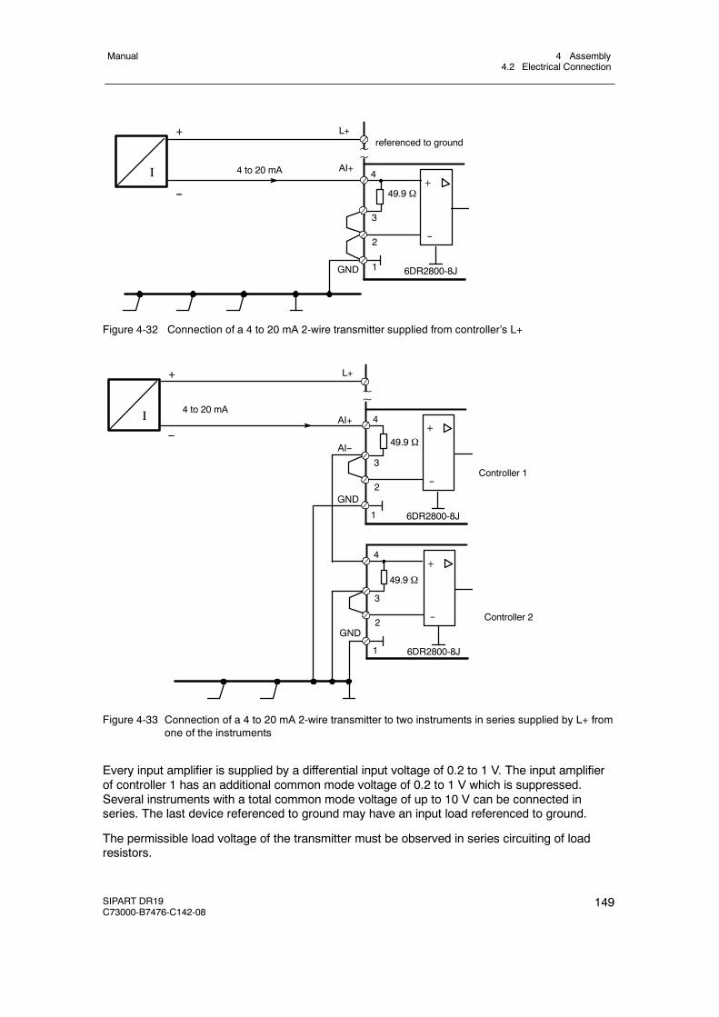
4 Assembly4.2 Electrical Connection
Manual
SIPART DR19C73000-B7476-C142-08
149
4 to 20 mA AI+
L+
--
referenced to ground~~
49.9 Ω
6DR2800-8J
3
+
--
GND
2
1
4I
+
Figure 4-32 Connection of a 4 to 20 mA 2-wire transmitter supplied from controller’s L+
49.9 Ω
6DR2800-8J
3
+
--
GND2
44 to 20 mA
Controller 1
AI+
AI--
L+
~~
Controller 2
1
49.9 Ω
6DR2800-8J
3
+
--2
4
1
GND
+
--
I
Figure 4-33 Connection of a 4 to 20 mA 2-wire transmitter to two instruments in series supplied by L+ fromone of the instruments
Every input amplifier is supplied by a differential input voltage of 0.2 to 1 V. The input amplifierof controller 1 has an additional common mode voltage of 0.2 to 1 V which is suppressed.Several instruments with a total common mode voltage of up to 10 V can be connected inseries. The last device referenced to ground may have an input load referenced to ground.
The permissible load voltage of the transmitter must be observed in series circuiting of loadresistors.
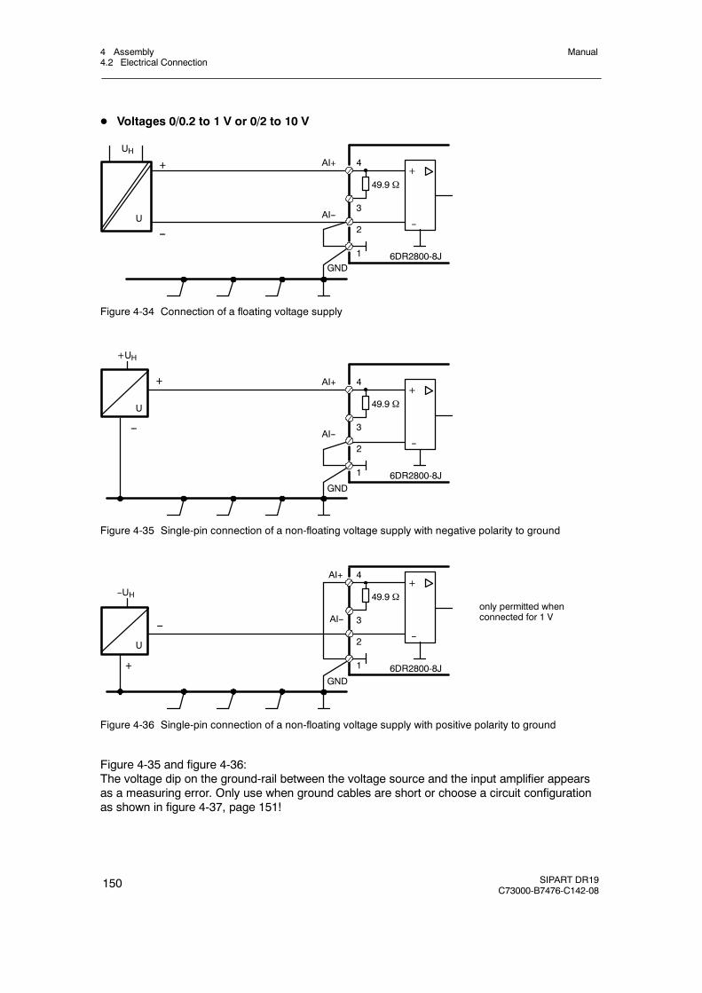
4 Assembly4.2 Electrical Connection
Manual
150 SIPART DR19C73000-B7476-C142-08
D Voltages 0/0.2 to 1 V or 0/2 to 10 V
+
UHAI+
AI--
GND
--
49.9 Ω
6DR2800-8J1
2
3
4
U
--
+
Figure 4-34 Connection of a floating voltage supply
+
+UH
AI+
AI--
GND
--
49.9 Ω
6DR2800-8J1
2
3
4
U
--
+
Figure 4-35 Single-pin connection of a non-floating voltage supply with negative polarity to ground
+--UH
AI+
AI--
GND
--
49.9 Ω
6DR2800-8J1
2
3
4
U
only permitted whenconnected for 1 V
--
+
Figure 4-36 Single-pin connection of a non-floating voltage supply with positive polarity to ground
Figure 4-35 and figure 4-36:The voltage dip on the ground-rail between the voltage source and the input amplifier appearsas a measuring error. Only use when ground cables are short or choose a circuit configurationas shown in figure 4-37, page 151!
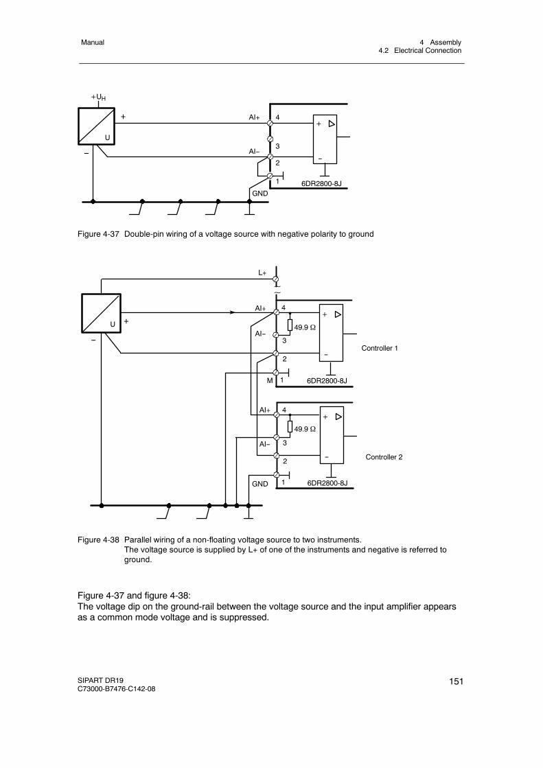
4 Assembly4.2 Electrical Connection
Manual
SIPART DR19C73000-B7476-C142-08
151
+
+UH
AI+
AI--
GND
--
6DR2800-8J1
2
3
4
U
--
+
Figure 4-37 Double-pin wiring of a voltage source with negative polarity to ground
6DR2800-8J
3
+
--
M
2
4
Controller 1
AI+
AI--
L+
~~
Controller 2
1
49.9 Ω
6DR2800-8J
3
+
--2
4
1GND
+
--
AI--
U 49.9 Ω
AI+
Figure 4-38 Parallel wiring of a non-floating voltage source to two instruments.The voltage source is supplied by L+ of one of the instruments and negative is referred toground.
Figure 4-37 and figure 4-38:The voltage dip on the ground-rail between the voltage source and the input amplifier appearsas a common mode voltage and is suppressed.
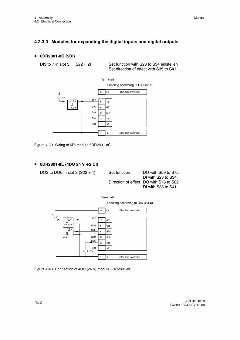
4 Assembly4.2 Electrical Connection
Manual
152 SIPART DR19C73000-B7476-C142-08
4.2.3.3 Modules for expanding the digital inputs and digital outputs
D 6DR2801-8C (5DI)
DI3 to 7 in slot 3 (S22 = 2) Set function with S23 to S34 einstellenSet direction of effect with S35 to S41
5 781
4 681
3 581
2 481
1 381
9 L+ Standard controller
11 ⊥ Standard controller
>13 V
<4.5 V
or
DI6
DI5
DI4
DI3
DI7
Terminals
Labeling according to DIN 45140
Figure 4-39 Wiring of 5DI module 6DR2801-8C
D 6DR2801-8E (4DO 24 V +2 DI)
DO3 to DO6 in slot 3 (S22 = 1) Set function DO with S59 to S75DI with S23 to S34
Direction of effect DO with S76 to S82DI with S35 to S41
6 481
5 685
4 585
3 485
2 385
1 381
9 L+ Standard controller
11 ⊥ Standard controller
>13 V
<4.5 V
or
≥ 19 V
≤ 30mA
DI4
DO6
DO5
DO4
DO3
DI3
Terminals
Labeling according to DIN 45140
Figure 4-40 Connection of 4DO (24 V)-module 6DR2801-8E
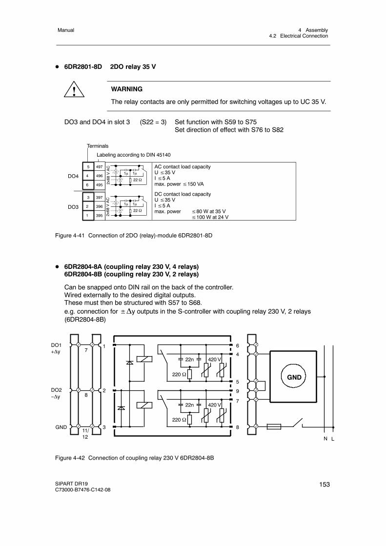
4 Assembly4.2 Electrical Connection
Manual
SIPART DR19C73000-B7476-C142-08
153
D 6DR2801-8D 2DO relay 35 V
! WARNING
The relay contacts are only permitted for switching voltages up to UC 35 V.
DO3 and DO4 in slot 3 (S22 = 3) Set function with S59 to S75Set direction of effect with S76 to S82
5 497
4 496
6 495
Terminals
Labeling according to DIN 45140
DO4
2x68
VAC
1μ 1μ
22 Ω
3 397
2 396
1 395
DO31μ 1μ
22 Ω
....
......
AC contact load capacityU≤35 VI≤5 Amax. power≤150 VA
DC contact load capacityU≤35 VI≤5 Amax. power ≤80 W at 35 V
≤100 W at 24 V2x68
VAC ....
......
Figure 4-41 Connection of 2DO (relay)-module 6DR2801-8D
D 6DR2804-8A (coupling relay 230 V, 4 relays)6DR2804-8B (coupling relay 230 V, 2 relays)
Can be snapped onto DIN rail on the back of the controller.Wired externally to the desired digital outputs.These must then be structured with S57 to S68.e.g. connection for±Δy outputs in the S-controller with coupling relay 230 V, 2 relays(6DR2804-8B)
420 V
420 V
GND
DO1+Δy
DO2--Δy
220 Ω
22n
11/12
220 Ω
22n
N L
1
2
3
6
4
5
9
7
8GND
8
7
Figure 4-42 Connection of coupling relay 230 V 6DR2804-8B
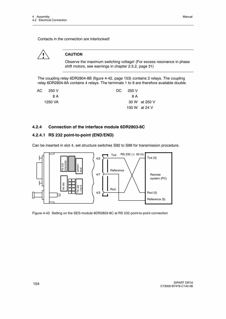
4 Assembly4.2 Electrical Connection
Manual
154 SIPART DR19C73000-B7476-C142-08
Contacts in the connection are interlocked!
! CAUTION
Observe the maximum switching voltage! (For excess resonance in phaseshift motors, see warnings in chapter 2.5.2, page 31)
The coupling relay 6DR2804-8B (figure 4-42, page 153) contains 2 relays. The couplingrelay 6DR2804-8A contains 4 relays. The terminals 1 to 9 are therefore available double.
AC 250 V8 A
1250 VA
DC 250 V8 A
30 W at 250 V100 W at 24 V
4.2.4 Connection of the interface module 6DR2803-8C
4.2.4.1 RS 232 point-to-point (END/END)
Can be inserted in slot 4, set structure switches S92 to S99 for transmission procedure.
Reference
Rxd
TxdTxd (3)
Rxd (2)
Reference (5)
Remotesystem (PC)
RS 232 (≤ 50 m)4/2
4/7
4/3
RS232
END/END
SIPART-
BUS
RS485
RS485
+150
R
Figure 4-43 Setting on the SES-module 6DR2803-8C at RS 232 point-to-point connection
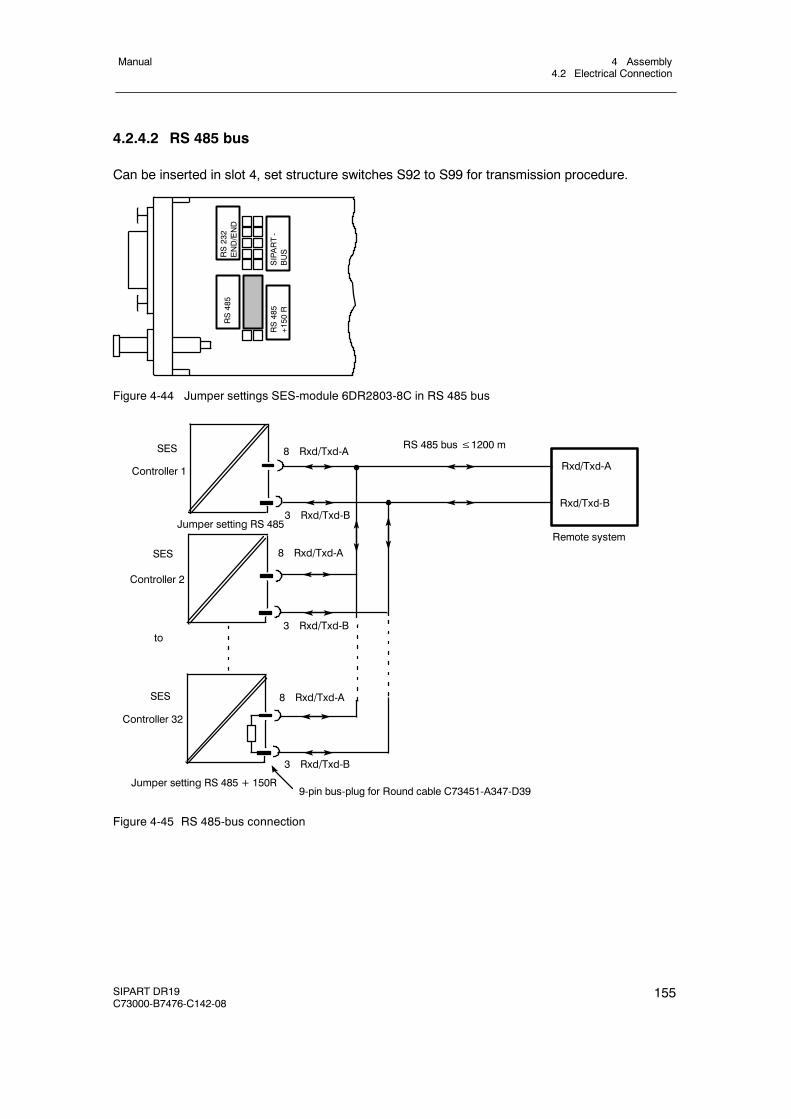
4 Assembly4.2 Electrical Connection
Manual
SIPART DR19C73000-B7476-C142-08
155
4.2.4.2 RS 485 bus
Can be inserted in slot 4, set structure switches S92 to S99 for transmission procedure.
RS232
END/END
SIPART-
BUS
RS485
RS485
+150
R
Figure 4-44 Jumper settings SES-module 6DR2803-8C in RS 485 bus
Controller 32
RS 485 bus≤1200 mSES
Remote system
Controller 1
Controller 2
to
Rxd/Txd-B
Rxd/Txd-A
9-pin bus-plug for Round cable C73451-A347-D39
8 Rxd/Txd-A
8 Rxd/Txd-A
8 Rxd/Txd-A
3 Rxd/Txd-B
3 Rxd/Txd-B
3 Rxd/Txd-B
SES
SES
Jumper setting RS 485
Jumper setting RS 485 + 150R
Figure 4-45 RS 485-bus connection
4 Assembly4.2 Electrical Connection
Manual
156 SIPART DR19C73000-B7476-C142-08
. NOTE on the line termination
The RS 485-bus must be terminated with its characteristic impedance. To do this,the terminating resistor in the “last” bus user is switched by plugging the codingbridge appropriately.See the SIMATIC S5-manual Distributed I/O System ET 200 for detailed descrip-tions and notes on cable and bus cable laying. “Distributed I/O system ET 200” tofind. Order number EWA 4NEB 8126114-*
4.2.4.3 PROFIBUS-DP, 6DR2803-8P
Technical Data
Transmittable signals RS 485, PROFIBUS-DP-protocolTransmittable data Operating state, process variables, parameters and
structure switchesTransmission procedurePROFIBUS-/-DP-protocol
According to DIN 19245, Part 1 and Part 3(EN 50170)
Transmission speed 9.6 kbit/s to 1.5 Mbit/sStation number 0 to 125 (note software version)Time monitoring of the data traffic Can be structured on the controller in connection
with DP watchdogElectrical isolation betweenRxd/Txd-P/-N and the controller
50 V UC common mode voltage
Test voltage 500 V ACRepeater-control signal CNTR-P TTL-level with 1 TTL loadSupply voltage VP (5 V) 5 V --0.4/+0.2 V/+0.2 V, short-circuit proofLine lengths, per segment at1.5 MBit/s
200 m; for other data see ET 200Manual 6ES5 998-3ES22
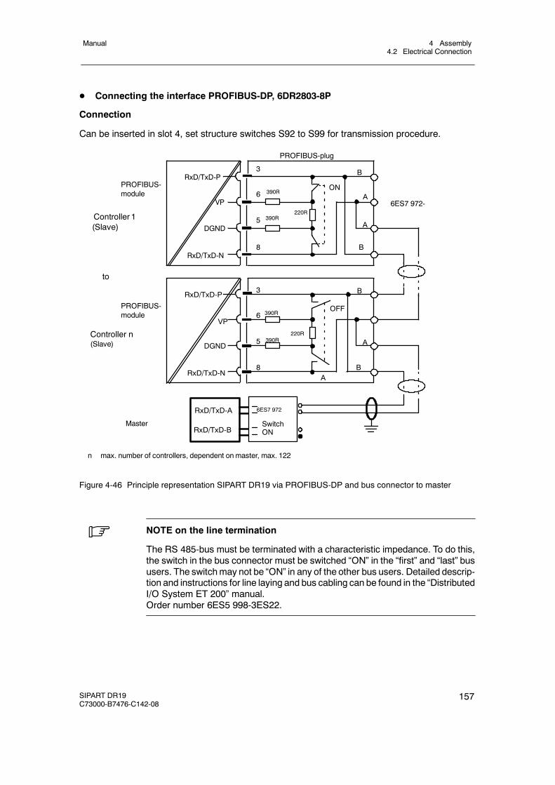
4 Assembly4.2 Electrical Connection
Manual
SIPART DR19C73000-B7476-C142-08
157
D Connecting the interface PROFIBUS-DP, 6DR2803-8P
Connection
Can be inserted in slot 4, set structure switches S92 to S99 for transmission procedure.
B
A
A
RxD/TxD-P
VP390R
3
6ON
DGND5
220R390R
PROFIBUS-module
PROFIBUS-plug
Controller 1(Slave)
RxD/TxD-N8
B
Controller n(Slave)
to
RxD/TxD-P
VP390R
3
6OFF
DGND5
220R390R
RxD/TxD-N8
B
A
A
B
PROFIBUS-module
RxD/TxD-A
RxD/TxD-BMaster
n max. number of controllers, dependent onmaster, max. 122
6ES7 972-
6ES7 972
SwitchON
Figure 4-46 Principle representation SIPART DR19 via PROFIBUS-DP and bus connector to master
. NOTE on the line termination
The RS 485-bus must be terminated with a characteristic impedance. To do this,the switch in the bus connector must be switched “ON” in the “first” and “last” bususers. The switchmay not be “ON” in any of the other bus users. Detailed descrip-tion and instructions for line laying and bus cabling can be found in the “DistributedI/O System ET 200” manual.Order number 6ES5 998-3ES22.

4 Assembly4.2 Electrical Connection
Manual
158 SIPART DR19C73000-B7476-C142-08
5 Operation5.1 General
Manual
SIPART DR19C73000-B7476-C142-08
159
5 Operation
5.1 General
D Operating modes
The SIPART DR19 is operated completely by the operating keys of the front module. Thefunction of the operating panel can be switched between three main levels:
Process operationmode
The process values x, w, y and the controller status are displayed,the process operation mode can be controlled by the operating keys.
Selection mode Here the list is selected which can be changed or activated in theconfiguration mode. These are the following lists:
onPA Online parameters(AdAP) Start adaptationoFPA Offline parameters(CLPA) Program controller/transmitterStrS Structure switchesCAE1 Set analog input AI1(CAE3) Set UNI-moduleAPSt all preset
The lists for onPA, oFPA, StrS, CAE1 and APST are always dis-played in the selection level.The lists for AdAP, CLPA and CAE3 only appear in the display whenthey have been selected by structure switches.
Configuration modes Settings are made in the selected list or functions are activated.
Some of the keys and displays on the front module are assigned different control and displayfunctions when the operating mode is changed. See the description of the respective mainlevel for details.
D Operating locks
Operation of the controller or access to the selection or configuration modes can be lockedby digital signals. The following blocking steps are possible:
bLb Blocking, OperationThe complete operation of the controller is blocked. Exception: Switching of thedigital display w/y (2). “bLb” appears in the display on pressing the operating keys.
bLS Blocking, StructuringBlocking the lists CLPA, oFPA, StrS, CAE1, CAE3 and APSt.Only the list for onPA and AdAP is accessible. “bLS” appears in the display whenthe blocked mode is called
bLPS Blocking, Parameterization and StructuringThe complete selection and configuration mode is blocked. The process operationmode is free. “bLPS” appears in the display when the blocked mode is called
5 Operation5.2 Process operation mode
Manual
160 SIPART DR19C73000-B7476-C142-08
D Behavior of the controller in the factory setting
SIPART DR19 operates as a fixed value controller in the factory setting.For safety reasons the online parameters, “proportional action factor Kp” and the “integralaction time Tn” are preset to uncritical values.
It is absolutely essential that these parameters be set to suit the requirements of yourcontrolled system.
5.2 Process operation mode
5.2.1 General
D Control elements
See page 5 for the control and display elements.
Due to the design and color scheme of the operating front panel, the control elements andthe labeling, operation of the SIPART DR19 in process mode requires no detailed explana-tion.
D Actual value
The four-digit PV-X-digital displays (1) show the actual value.
D Setpoint
The four-digit SP-W/OUT-Y-digital display (2) shows the active setpoint (when the greenw-LED (5) lights steadily) (see structure switch S88). The green internal/external key (13)switches between the internal and external setpoint. The internal setpoint is set with thegreen Δw/Δy-adjusting keys (7), (8). The green internal LED (15) signals operation with theinternal setpoint, the C LED (14) also lights green when there is no CB control signal.
However, a setpoint setting is only possible when the green LEDs (5 and 15) signal that theSP-W/OUT digital display is showing the setpoint and internal mode is set.
D Control difference
The analog display (3) shows the control difference xd in the factory setting (see structureswitch S89).
D Manipulated variable
Independently of the variable output at analog output AO, the four-digit SP-W/OUT-Y digitaldisplay (2) indicates the manipulated variable y (when the x-LED (4) and the w-LED (5) areout) or the position feedback yR or split range y1/y2 according to the position of the structureswitch S55.
5 Operation5.2 Process operation mode
Manual
SIPART DR19C73000-B7476-C142-08
161
The setpoint display is switched over to the manipulated variable display by pressing theShift key (6) once (x-LED (4) and w-LED (5) are out) or in manual mode (manual-LED (11)lights up) or in y-external mode (y-external-LED (10) lights).
The M/A-key (9) switches between manual- and automatic operation. The yellow manualLED (11) signals by lighting steadily or flashing that manual operation has been activated.Lighting of the also yellow y-external LED (13) signals an external intervention in the ma-nipulated variable, i.e. a tracking, safety or blocking operation. The manipulated variable canbe adjusted in manual mode with the yellow±Δy-keys (7), (8) The±Δy-LEDs (12) showthe output of the positioning increments in all operating modes of the S-controller.
D Adaptation
The adaptation LED (16) signals the active adaptation procedure by flashing.
D Lamp test
If the button (6) is kept pressed for longer than 5 s, all LEDs on the front of the controller aredriven independently of the respective display until the button is released again. The originaldisplay position is restored after checking the lamp function.
D Display of software version and controller type
The SIPART DR19 controller software will be improved in the course of new knowledge. Therespective version of the software is stored in the EPROM with identification and can becalled as follows:
" Run the lamp test with the button (6),
" Then press the button (13) additionally. On the digital displays (1) and (2) theidentification can now be read off for the controller software version.
D Alarms
The red alarm LEDs (17) signal exceeding or dropping below the limit values A1 to A4.The alarms A1 to A4 are set by the offline parameters. Assignment to the variables to bemonitored is effected with the structure switches S83, S84, their function with S85, S86 andtheir display and setting with S87.
5.2.2 Operation and displays in the program controller setting (S1 = 5)
With the cyclic counter display (S88) the x-display (1) and the bargraphs (3) can be switchedover to time and interval display. At S88 = 7, flashing x-LED (4) and w-LED (5) the x-display (1)shows the remaining time in the interval and the w/y-display (2) the target setpoint wpz of thecurrently running interval.
The bargraph (3) indicates the time from the start and the current interval. It also provides in-formation whether the program has been stopped.
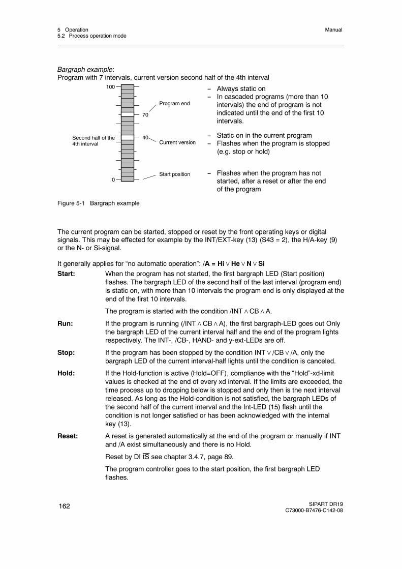
5 Operation5.2 Process operation mode
Manual
162 SIPART DR19C73000-B7476-C142-08
Bargraph example:Program with 7 intervals, current version second half of the 4th interval
40
70
100
0Start position
Current version
Program end
Second half of the4th interval
-- Always static on-- In cascaded programs (more than 10
intervals) the end of program is notindicated until the end of the first 10intervals.
-- Static on in the current program-- Flashes when the program is stopped
(e.g. stop or hold)
-- Flashes when the program has notstarted, after a reset or after the endof the program
Figure 5-1 Bargraph example
The current program can be started, stopped or reset by the front operating keys or digitalsignals. This may be effected for example by the INT/EXT-key (13) (S43 = 2), the H/A-key (9)or the N- or Si-signal.
It generally applies for “no automatic operation”: /A = Hi∨He∨N∨SiStart: When the program has not started, the first bargraph LED (Start position)
flashes. The bargraph LED of the second half of the last interval (program end)is static on, with more than 10 intervals the program end is only displayed at theend of the first 10 intervals.
The program is started with the condition /INT∧CB∧A.
Run: If the program is running (/INT∧CB∧A), the first bargraph-LED goes out Onlythe bargraph LED of the current interval half and the end of the program lightsrespectively. The INT-, /CB-, HAND- and y-ext-LEDs are off.
Stop: If the program has been stopped by the condition INT∨/CB∨/A, only thebargraph LED of the current interval-half lights until the condition is canceled.
Hold: If the Hold-function is active (Hold=OFF), compliance with the “Hold”-xd-limitvalues is checked at the end of every xd interval. If the limits are exceeded, thetime process up to dropping below is stopped and only then is the next intervalreleased. As long as the Hold-condition is not satisfied, the bargraph LEDs ofthe second half of the current interval and the Int-LED (15) flash until thecondition is not longer satisfied or has been acknowledged with the internalkey (13).
Reset: A reset is generated automatically at the end of the program or manually if INTand /A exist simultaneously and there is no Hold.
Reset by DI tS see chapter 3.4.7, page 89.
The program controller goes to the start position, the first bargraph LEDflashes.
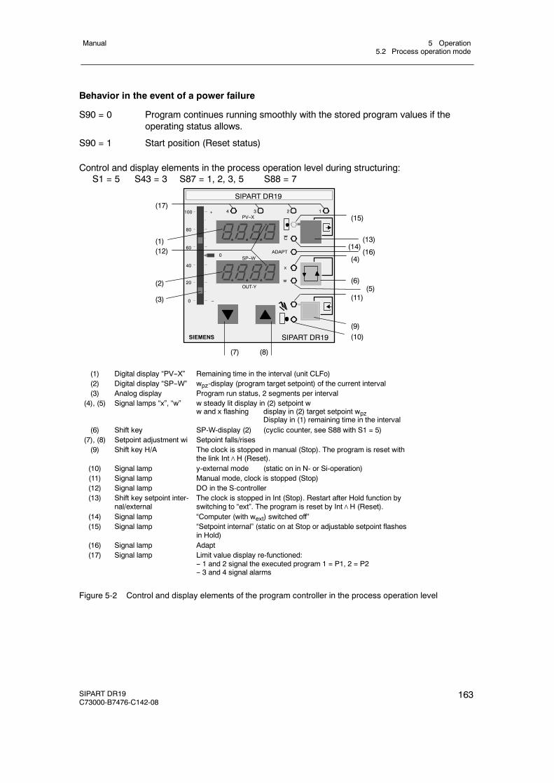
5 Operation5.2 Process operation mode
Manual
SIPART DR19C73000-B7476-C142-08
163
Behavior in the event of a power failure
S90 = 0 Program continues running smoothly with the stored program values if theoperating status allows.
S90 = 1 Start position (Reset status)
Control and display elements in the process operation level during structuring:S1 = 5 S43 = 3 S87 = 1, 2, 3, 5 S88 = 7
SIPART DR19
SIEMENS
OUT-Y
C
x
w
ADAPT
1234
SP--W
PV--X
SIPART DR19
100
80
0
20
40
60
+
--
0
(7) (8)
(17)
(1)
(2)
(3)
(10)(9)
(11)(5)
(6)
(4)(16)
(14)(13)
(15)
(12)
(1) Digital display “PV--X” Remaining time in the interval (unit CLFo)(2) Digital display “SP--W” wpz-display (program target setpoint) of the current interval(3) Analog display Program run status, 2 segments per interval
(4), (5) Signal lamps “x”, “w” w steady lit display in (2) setpoint ww and x flashing display in (2) target setpoint wpz
Display in (1) remaining time in the interval(6) Shift key SP-W-display (2) (cyclic counter, see S88 with S1 = 5)
(7), (8) Setpoint adjustment wi Setpoint falls/rises(9) Shift key H/A The clock is stopped in manual (Stop). The program is reset with
the link Int∧H (Reset).(10) Signal lamp y-external mode (static on in N- or Si-operation)(11) Signal lamp Manual mode, clock is stopped (Stop)(12) Signal lamp DO in the S-controller(13) Shift key setpoint inter-
nal/externalThe clock is stopped in Int (Stop). Restart after Hold function byswitching to “ext”. The program is reset by Int∧H (Reset).
(14) Signal lamp “Computer (with wext) switched off”(15) Signal lamp “Setpoint internal” (static on at Stop or adjustable setpoint flashes
in Hold)(16) Signal lamp Adapt(17) Signal lamp Limit value display re-functioned:
-- 1 and 2 signal the executed program 1 = P1, 2 = P2-- 3 and 4 signal alarms
Figure 5-2 Control and display elements of the program controller in the process operation level
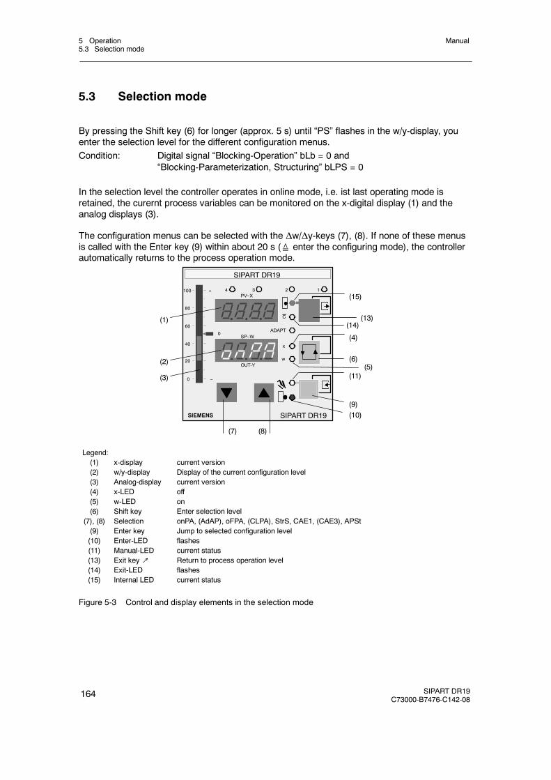
5 Operation5.3 Selection mode
Manual
164 SIPART DR19C73000-B7476-C142-08
5.3 Selection mode
By pressing the Shift key (6) for longer (approx. 5 s) until “PS” flashes in the w/y-display, youenter the selection level for the different configuration menus.Condition: Digital signal “Blocking-Operation” bLb = 0 and
“Blocking-Parameterization, Structuring” bLPS = 0
In the selection level the controller operates in online mode, i.e. ist last operating mode isretained, the curernt process variables can be monitored on the x-digital display (1) and theanalog displays (3).
The configuration menus can be selected with the Δw/Δy-keys (7), (8). If none of these menusis called with the Enter key (9) within about 20 s (≙ enter the configuring mode), the controllerautomatically returns to the process operation mode.
SIPART DR19
SIEMENS
OUT-Y
C
x
w
ADAPT
1234
SP--W
PV--X
SIPART DR19
100
80
0
20
40
60
+
--
0
(7) (8)
(1)
(2)
(3)
(10)(9)
(11)(5)
(6)
(4)
(14)(13)
(15)
Legend:(1) x-display current version(2) w/y-display Display of the current configuration level(3) Analog-display current version(4) x-LED off(5) w-LED on(6) Shift key Enter selection level
(7), (8) Selection onPA, (AdAP), oFPA, (CLPA), StrS, CAE1, (CAE3), APSt(9) Enter key Jump to selected configuration level(10) Enter-LED flashes(11) Manual-LED current status(13) Exit key↗ Return to process operation level(14) Exit-LED flashes(15) Internal LED current status
Figure 5-3 Control and display elements in the selection mode
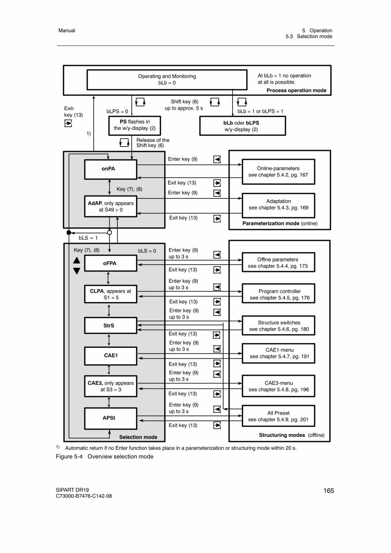
5 Operation5.3 Selection mode
Manual
SIPART DR19C73000-B7476-C142-08
165
Exit key (13)
1)
bLb = 1 or bLPS = 1bLPS = 0
Enter key (9)
Shift key (6)up to approx. 5 s
Process operation mode
Operating and MonitoringbLb = 0
onPA
Exit-key (13)
PS flashes inthe w/y-display (2)
Online-parameterssee chapter 5.4.2, pg. 167
Adaptationsee chapter 5.4.3, pg. 169
Parameterization mode (online)
AdAP, only appearsat S49 > 0
bLb oder bLPSw/y-display (2)
At bLb = 1 no operationat all is possible.
bLS = 1
bLS = 0
StrS
CAE3, only appearsat S3 > 3
APSt
Selection mode
Offine parameterssee chapter 5.4.4, pg. 173
Structure switchessee chapter 5.4.6, pg. 180
CAE3-menusee chapter 5.4.8, pg. 196
All Presetsee chapter 5.4.9, pg. 201
Exit key (13)
Structuring modes (offline)
Release of theShift key (6)
Enter key (9)up to 3 s
Key (7), (8)
Key (7), (8)
Exit key (13)
Enter key (9)
Exit key (13)
Enter key (9)up to 3 s
Exit key (13)
CAE1CAE1-menu
see chapter 5.4.7, pg. 191
Enter key (9)up to 3 s
Enter key (9)up to 3 s
Exit key (13)
CLPA, appears atS1 = 5
Program controllersee chapter 5.4.5, pg. 176
Enter key (9)up to 3 s
Exit key (13)
oFPA
Enter key (9)up to 3 s
Exit key (13)
1) Automatic return if no Enter function takes place in a parameterization or structuring mode within 20 s.
Figure 5-4 Overview selection mode
5 Operation5.4 Configuration modes
Manual
166 SIPART DR19C73000-B7476-C142-08
5.4 Configuration modes
5.4.1 General, Online and Offline modes
The settings in the configuration modes onPA and AdAP and the selection in the selectionmode (see fig. 5-4, page 165 takes place in online mode, i.e. the controller continues operatingin its last mode. Entry into the onPA and AdAP-levels takes place directly from the selectionlevels by pressing the Enter key (9). The analog xd-display (3) continues to display the processimage so that the reaction of the controlled system to parameter changes can be read directly.The internal LED (15) and Manual LED (11) and the Alarm LEDs A1 to A4 indicate the currentoperating state. The internal/external key (13) becomes the Exit key, the corresponding C--LED(14) indicates ready to exit, i.e. every time the LED flashes, pressing the Exit key jumps fromthe selected mode to the next level up in the hierarchy.
The automatic/manual key (9) becomes the Enter key, the corresponding y external LED (10)indicates ready to enter, i.e. whenever the LED flashes, pressing the Enter key jumps to thenext level down in the hierarchy.
Pressing the Enter key (9) for 3 s switches from the pre-selection level to the offline level withthe oFPA, StrS, CAE1, CAE3 and APSt menus. The user stays offline when returning (fromoffline level) to the pre-selection level. When subsequently entering another offline-level thethree-second-time condition is omitted. The three-second time condition for entering an offlinemenu is only valid again after exiting the offline mode by selecting an online mode with theonPA and Adap menus or exiting the preselection mode. The controller switches into theabsolute manual mode (offline mode), i.e. the last manipulated variable of the online mode isretained (in K-controllers the last manipulated variable, in S-controllers no positioning in-crements are output). A change in the manipulated variable with the±Δy-keys (7), (8) is notpossible, the control signals N, Si and±yBL are inactive. The analog output, the digital outputsand the alarm LEDs A1 to A4 are held at the last value or status. To indicate the offline-mode,the analog xd-display (3) shows a striped pattern and the manual LED (11) lights up. The abso-lute manual mode is retained when returning to the parameterization preselection mode (onlinemode) or the process operation mode from the structuring preselection mode with the Exit key(16). This also applies when only automatic operation has been selected with S52 = 1. The con-troller must also be reactivated in the process operation mode for safety reasons by switchingto automatic operation.
The internal LED (15) is out during offline operation. The Enter key (9) and Exit key (13) and themanual LED (11), the internal LED (15) and C-LED (14) have the same function as in the onlineconfiguration levels.
If the control signal bLPS = 1, parameterization and structuring is blocked, after pressing theShift key (6) bPLS appears in the w/y display (2).
If the control signal bLS = 1, structuring is blocked. Only onPA and AdAP appear in theselection mode.
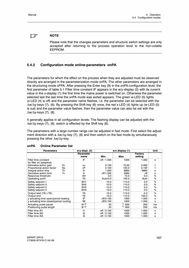
5 Operation5.4 Configuration modes
Manual
SIPART DR19C73000-B7476-C142-08
167
. NOTE
Please note that the changes parameters and structure switch settings are onlyaccepted after returning to the process operation level to the non-volatileEEPROM.
5.4.2 Configuration mode online-parameters onPA
The parameters for which the effect on the process when they are adjusted must be observeddirectly are arranged in the parameterization mode onPA. The other parameters are arranged inthe structuring mode oFPA. After pressing the Enter key (9) in the onPA-configuration level, thefirst parameter of table 5-1 Filter time constant tF appears in the w/y-display (2) with its curerntvalue in the x-display (1) the first time the mains power is switched on. Otherwise the parameterselected last the last time the onPA mode was exited appears. The green w-LED (5) lights(x-LED (4) is off) and the parameter name flashes, i.e. the parameter can be selected with theΔw/Δy-keys (7), (8). By pressing the Shift key (6) once, the red x-LED (4) lights up (w-LED (5)is out) and the parameter value flashes, then the parameter value can also be set with theΔw/Δy-keys (7), (8).
It generally applies in all configuration levels: The flashing display can be adjusted with theΔw/Δy-keys (7), (8), switch is effected by the Shift key (6).
The parameters with a large number range can be adjusted in fast mode. First select the adjust-ment direction with a Δw/Δy-key (7), (8) and then switch on the fast mode by simultaneouslypressing the other Δw/Δy-key.
onPA Online Parameter listParameters w/y-displ. (2) w/x display (1) Unit
Parametername Min. Max.
Factorysetting
Filter time constantfor filter xd (adaptive)Derivative action gain VvProportional action factor KpIntegral action time TnDerivative action time TvResponse thresholdOperating point
tF
uucPtntvAHY0
off / 1.000
0.1000.1001.000
off/1.0000.0
Auto/0.0
1000
10.00100.09984299210.0100.0
1.000
5.0000.1009984off0.0Auto
s
11ss%%
Safety setpoint 1Safety setpoint 2Safety setpoint 3Safety setpoint 4
SH1SH2SH3SH4
-10.0-10.0-10.0-10.0
110.0110.0110.0110.0
0.00.00.00.0
%%%%
Output start (YA≤YE)Output endy actuating time open/period heatingy actuating time closed/period cooling
YAYEtPtM
-10.0-10.0
off/0.100off/0.100
110.0110.010001000
-5.0105.01.0001.000
%%ss
Actuating pulse pausePositioning pulse length
tA 2)tE 2)
2020
1) 6001) 600
200200
msms
Filter time AI1Filter time AI2Filter time AI3
t1t2t3
off / 0.100off / 0.100off / 0.100
100010001000
1.0001.0001.000
sss
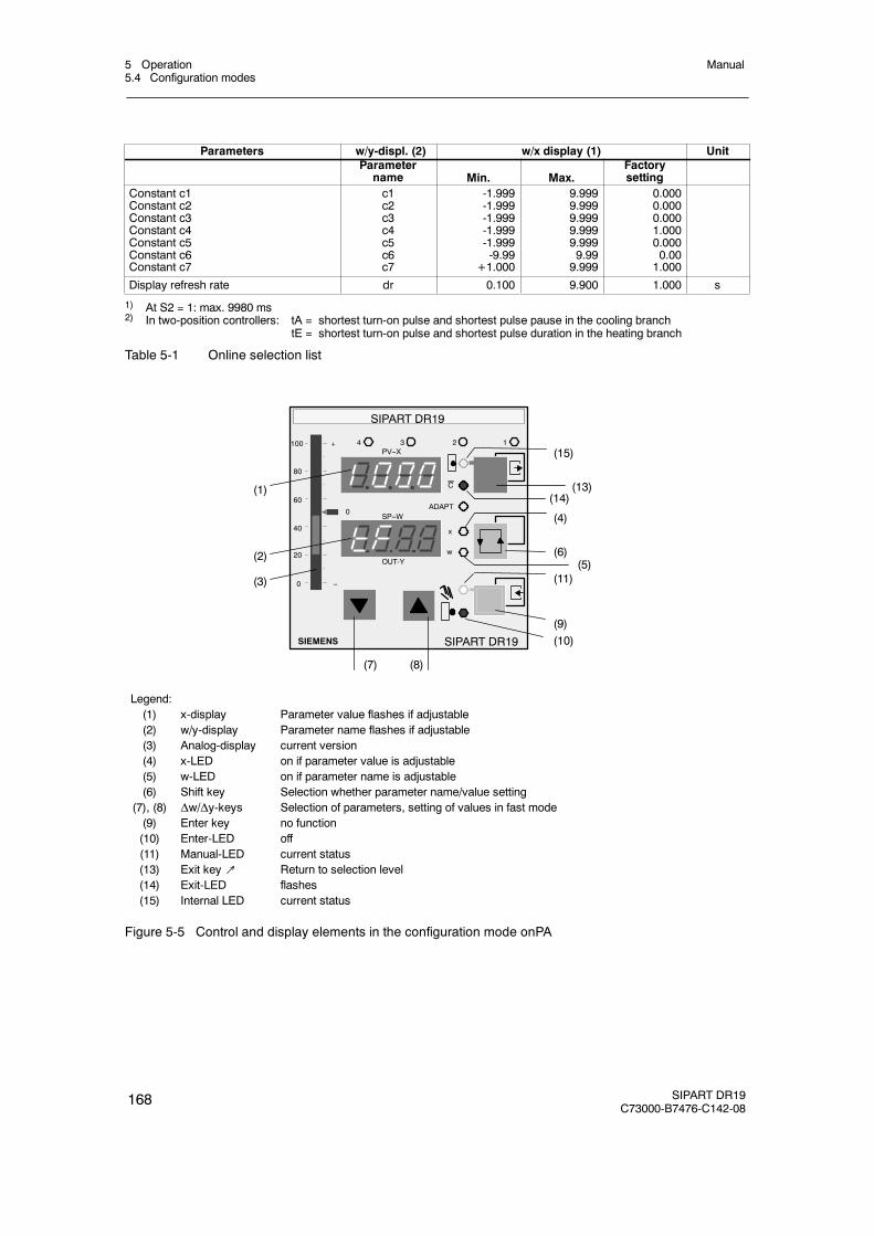
5 Operation5.4 Configuration modes
Manual
168 SIPART DR19C73000-B7476-C142-08
Parameters w/y-displ. (2) w/x display (1) UnitParametername Min. Max.
Factorysetting
Constant c1Constant c2Constant c3Constant c4Constant c5Constant c6Constant c7
c1c2c3c4c5c6c7
-1.999-1.999-1.999-1.999-1.999-9.99
+1.000
9.9999.9999.9999.9999.9999.999.999
0.0000.0000.0001.0000.0000.001.000
Display refresh rate dr 0.100 9.900 1.000 s
1) At S2 = 1: max. 9980 ms2) In two-position controllers: tA = shortest turn-on pulse and shortest pulse pause in the cooling branch
tE = shortest turn-on pulse and shortest pulse duration in the heating branch
Table 5-1 Online selection list
SIPART DR19
SIEMENS
OUT-Y
C
x
w
ADAPT
1234
SP--W
PV--X
SIPART DR19
100
80
0
20
40
60
+
--
0
(7) (8)
(1)
(2)
(3)
(10)(9)
(11)(5)
(6)
(4)
(14)(13)
(15)
Legend:(1) x-display Parameter value flashes if adjustable(2) w/y-display Parameter name flashes if adjustable(3) Analog-display current version(4) x-LED on if parameter value is adjustable(5) w-LED on if parameter name is adjustable(6) Shift key Selection whether parameter name/value setting
(7), (8) Δw/Δy-keys Selection of parameters, setting of values in fast mode(9) Enter key no function(10) Enter-LED off(11) Manual-LED current status(13) Exit key↗ Return to selection level(14) Exit-LED flashes(15) Internal LED current status
Figure 5-5 Control and display elements in the configuration mode onPA
5 Operation5.4 Configuration modes
Manual
SIPART DR19C73000-B7476-C142-08
169
5.4.3 Configuration mode adaptation AdAP
This mode only appears in the selection level if S49 > 0 ist (with adaptation). In theparameterization mode AdAP the control circuit is open, the limit value alarms and digitalcontrol signals are active
D Conditions for adaptation
- Structure switch S49 > 0 set.- The difference amount between the setpoint w and the actual value x must be greater
than 20 % at the starting point.- There may be no tracking or safety operation by the control signals.
Four different statuses are distinguished in the configuration level.
- pre adaptation- During adaptation- Aborted adaptation- post adaptation
D Pre adaptation
Adaptation can be started optionally in automatic or manual mode. In controlled systemswith low gain and low or no overshoot, the structure switch setting S49 = 1 is recommended.S49 = 2 should be selected at large gain of the controlled system and greater overshoot.
It is advisable to start in automatic mode because the controller operates automatically withthe determined parameters at the end of adaptation. If adaptation is started and ended inmanual mode, the controller outputs a manipulated value after adaptation which causes assmall as possible a control difference xd. The parameters YA and YE have no effect on theadaptation procedure.
Start of adaptation:
2. Enter the selection level with the Shift key (6) and select the configuration level AdAPwith the w/y-keys (7), (8). Enter-LED (10) flashes.
3. Call AdAP with the Enter key (9) AdAP and select the controller structure PI or PID withthe w/y-key (7), (8). Enter-LED (10) flashes as a start request.
4. Start adaptation with the Enter key (9) (Adapt LED (16) starts to flash).
D During adaptation
The AdAPT LED (16) flashes during adaptation. All the process variables can be observed.However, the w/y-keys (7), (8) are locked. The adaptation time depends on the delay time inthe process.
During the adaptation process you can switch from automatic to manual mode and viceversa. But this has no influence on the course of adaptation. The control circuit is open inany case. Only the status is determined which the controller adopts at the end of the adapta-tion process.
5 Operation5.4 Configuration modes
Manual
170 SIPART DR19C73000-B7476-C142-08
The controller outputs 100 % and 0 % of the manipulated variable y several times at theoutput during adaptation. This generates an oscillation of the controlled variable x within thetarget setpoint/start actual value band. The controller parameters are determined by thecurve (oscillation time, amplitude) (see chapter 3.9, page120).
D Aborted adaptation
If adaptation is aborted, the safety manipulated value YS is output, the controller goes intomanual mode, the AdAPT-LED (16) goes off and the old control parameters are retained
The manual abortion can be triggered at any time by pressing the Exit key (13). Thisreturns you to the process operation level.
Automatic abortion is accompanied by an error message (see table 5-2, page 172). Theerror messages are indicated in the digital x-display (1) and w/y-display (2). The Exit LED(14) flashes. The error message is acknowledged by pressing the Exit key (13), the con-troller returns to the process operation level.
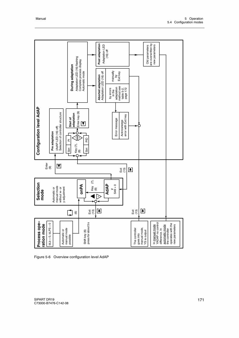
5 Operation5.4 Configuration modes
Manual
SIPART DR19C73000-B7476-C142-08
171
Process
ope--
rationmode
bLb=0,bLPS=0
Shiftkey(6)
pressforabout5s
Selection
mode
onPA
ConfigurationlevelAdAP
Pre
adaptation
(AdA
P-LED(16)off)
Selectionofcontrollerstructure
(6)
Exit
(13)
Enter
(9)
Key
(7),
(8)
Duringadaptation
AdaptationLE
D(16)flashing
Com
pleteprocessdisplay
Autom
aticmode
Aborted
adaptation
AdaptationLE
D(16)off
byerrors
inthe
adaptation
methodsee
table5-2,
page
172
manually
byExitkey
Inmanualm
ode
YADAPno
control
difference.In
automaticmode
thecontroller
operates
with
the
newparameters
The
controller
goes
into
manualm
ode,
YSisoutput
Autom
aticor
manualm
ode
possible
Postadaptation
AdaptationLE
D(16)off
Autom
aticor
manualm
ode
withoutw
-or
y-adjustment
AdAP
ifS49
>0
Exit
(13)
Key
(7),
(8)Strt
PI
Strt
PID
Oldparameters
areoverwrittenby
newparameters
+--
Startof
adaptation
Enterkey(9)
Exit
(13)
Errormessage
Acknowledge
errorwith
Exitkey
+
Figure 5-6 Overview configuration level AdAP
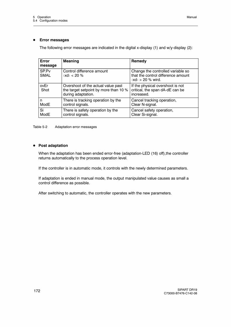
5 Operation5.4 Configuration modes
Manual
172 SIPART DR19C73000-B7476-C142-08
D Error messages
The following error messages are indicated in the digital x-display (1) and w/y-display (2):
Errormessage
Meaning Remedy
SP.PvSMAL
Control difference amountxd < 20 %
Change the controlled variable sothat the control difference amountxd > 20 % wird.
ovErShot
Overshoot of the actual value pastthe target setpoint by more than 10 %during adaptation.
If the physical overshoot is notcritical, the span dA-dE can beincreased.
nModE
There is tracking operation by thecontrol signals.
Cancel tracking operation,Clear N-signal.
SiModE
There is safety operation by thecontrol signals.
Cancel safety operation,Clear Si-signal.
Table 5-2 Adaptation error messages
D Post adaptation
When the adaptation has been ended error-free (adaptation-LED (16) off),the controllerreturns automatically to the process operation level.
If the controller is in automatic mode, it controls with the newly determined parameters.
If adaptation is ended in manual mode, the output manipulated value causes as small acontrol difference as possible.
After switching to automatic, the controller operates with the new parameters.
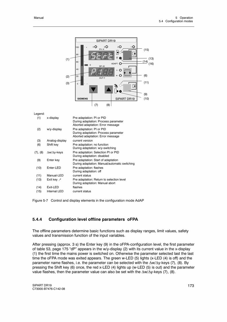
5 Operation5.4 Configuration modes
Manual
SIPART DR19C73000-B7476-C142-08
173
SIPART DR19
SIEMENS
OUT-Y
C
x
w
ADAPT
1234
SP--W
PV--X
SIPART DR19
100
80
0
20
40
60
+
--
0
(7) (8)
(1)
(2)
(3)
(10)(9)
(11)
(6)
(16)(14)
(13)
(15)
Legend:(1) x-display Pre adaptation: PI or PID
During adaptation: Process parameterAborted adaptation: Error message
(2) w/y-display Pre adaptation: PI or PIDDuring adaptation: Process parameterAborted adaptation: Error message
(3) Analog-display current version(6) Shift key Pre adaptation: no function
During adaptation: w/y-switching(7), (8) Δw/Δy-keys Pre adaptation: Selection PI or PID
During adaptation: disabled(9) Enter key Pre adaptation: Start of adaptation
During adaptation: Manual/automatic switching(10) Enter-LED Pre adaptation: flashes
During adaptation: off(11) Manual-LED current status(13) Exit key↗ Pre adaptation: Return to selection level
During adaptation: Manual abort(14) Exit-LED flashes(15) Internal LED current status
Figure 5-7 Control and display elements in the configuration mode AdAP
5.4.4 Configuration level offline parameters oFPA
The offline parameters determine basic functions such as display ranges, limit values, safetyvalues and transmission function of the input variables.
After pressing (approx. 3 s) the Enter key (9) in the oFPA-configuration level, the first parameterof table 53, page 175 “dP” appears in the w/y-display (2) with its current value in the x-display(1) the first time the mains power is switched on. Otherwise the parameter selected last the lasttime the oFPA mode was exited appears. The green w-LED (5) lights (x-LED (4) is off) and theparameter name flashes, i.e. the parameter can be selected with the Δw/Δy-keys (7), (8). Bypressing the Shift key (6) once, the red x-LED (4) lights up (w-LED (5) is out) and the parametervalue flashes, then the parameter value can also be set with the Δw/Δy-keys (7), (8).
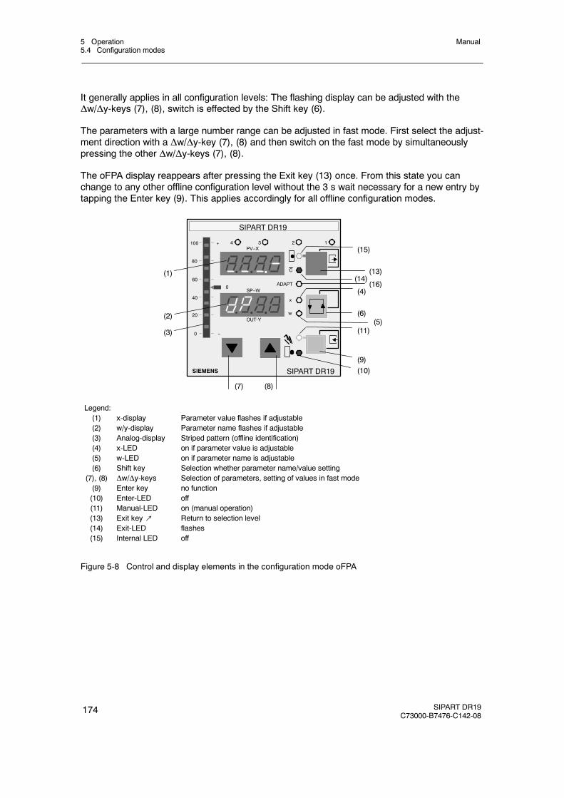
5 Operation5.4 Configuration modes
Manual
174 SIPART DR19C73000-B7476-C142-08
It generally applies in all configuration levels: The flashing display can be adjusted with theΔw/Δy-keys (7), (8), switch is effected by the Shift key (6).
The parameters with a large number range can be adjusted in fast mode. First select the adjust-ment direction with a Δw/Δy-key (7), (8) and then switch on the fast mode by simultaneouslypressing the other Δw/Δy-keys (7), (8).
The oFPA display reappears after pressing the Exit key (13) once. From this state you canchange to any other offline configuration level without the 3 s wait necessary for a new entry bytapping the Enter key (9). This applies accordingly for all offline configuration modes.
(1)
(2)
(3)
SIPART DR19
SIEMENS
OUT-Y
C
x
w
ADAPT
1234
SP--W
PV--X
SIPART DR19
(7) (8)
(10)(9)
(11)
(6)
(4)(16)
(14)(13)
(15)
(5)
100
80
0
20
40
60
+
--
0
Legend:(1) x-display Parameter value flashes if adjustable(2) w/y-display Parameter name flashes if adjustable(3) Analog-display Striped pattern (offline identification)(4) x-LED on if parameter value is adjustable(5) w-LED on if parameter name is adjustable(6) Shift key Selection whether parameter name/value setting
(7), (8) Δw/Δy-keys Selection of parameters, setting of values in fast mode(9) Enter key no function(10) Enter-LED off(11) Manual-LED on (manual operation)(13) Exit key↗ Return to selection level(14) Exit-LED flashes(15) Internal LED off
Figure 5-8 Control and display elements in the configuration mode oFPA
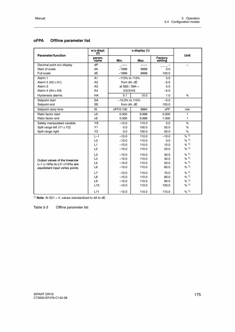
5 Operation5.4 Configuration modes
Manual
SIPART DR19C73000-B7476-C142-08
175
oFPA Offline parameter list
Parameter/function
w/y-displ.(2)
x-display (1)
UnitParameter/functionparam.name Min. Max.
Factorysetting
Unit
Decimal point w/x display dP _.------ -------- _ _ _.-- --Start of scale dA --1999 9999 0.0Full scale dE --1999 9999 100.0
Alarm 1 A1 --110% to 110% 5.0Alarm 2 (A2≤A1) A2 from dA, dE --5.0Alarm 3 A3 at S83 / S84 = 5.0Alarm 4 (A4≤A3) A4 0/2/3/4/5 --5.0
Hysteresis alarms HA 0.1 10.0 1.0 %
Setpoint start SA --10,0% to 110% --5.0Setpoint end SE from dA, dE 105.0
Setpoint ramp time tS oFF/0.100 9984 oFF min
Ratio factor start vA 0.000 9.999 0.000 1Ratio factor end vE 0.000 9.999 1.000 1
Safety manipulated variable YS --10.0 110.0 0.0 %Split range left (Y1≤Y2) Y1 0.0 100.0 50.0 %Split range right Y2 0.0 100.0 50.0 %
L--1 --10.0 110.0 --10.0 % 1)
L0 --10.0 110.0 0.0 % 1)
L1 --10.0 110.0 10.0 % 1)
L2 --10.0 110.0 20.0 % 1)
L3 --10.0 110.0 30.0 % 1)
Output values of the linearizer L4 --10.0 110.0 40.0 % 1)Output values of the linearizerL--1 (--10%) to L11 (110%) are L5 --10.0 110.0 50.0 % 1)L--1 (--10%) to L11 (110%) areequidistant input vertex points L6 --10.0 110.0 60.0 % 1)equidistant input vertex points
L7 --10.0 110.0 70.0 % 1)
L8 --10.0 110.0 80.0 % 1)
L9 --10.0 110.0 90.0 % 1)
L10 --10.0 110.0 100.0 % 1)
L11 --10.0 110.0 110.0 % 1)
1) Note: At S21 = 4, values standardized to dA to dE.
Table 5-3 Offline parameter list
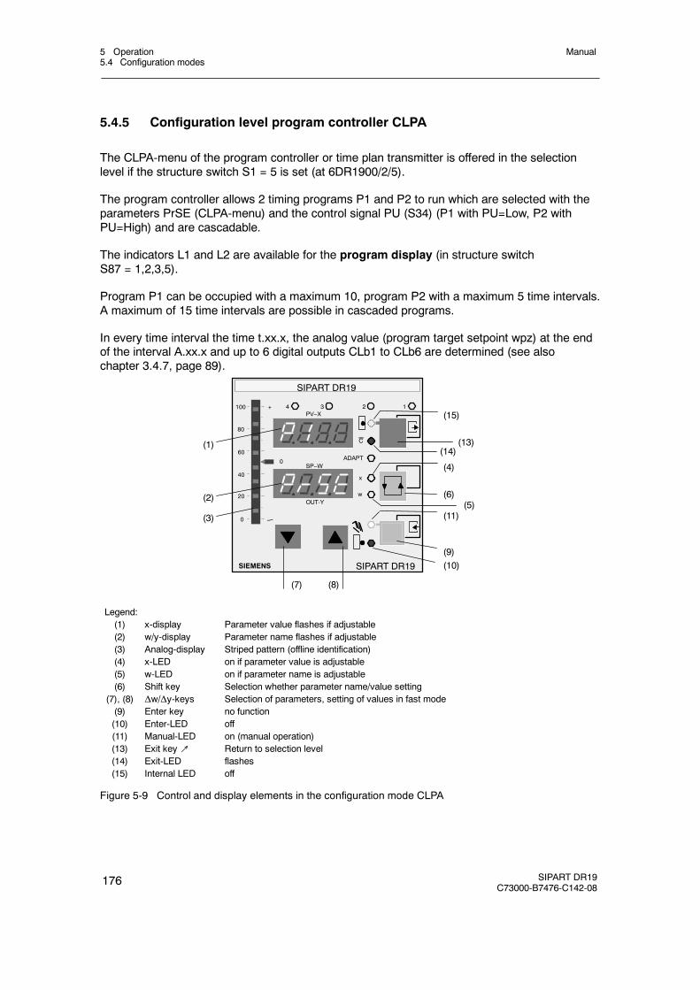
5 Operation5.4 Configuration modes
Manual
176 SIPART DR19C73000-B7476-C142-08
5.4.5 Configuration level program controller CLPA
The CLPA-menu of the program controller or time plan transmitter is offered in the selectionlevel if the structure switch S1 = 5 is set (at 6DR1900/2/5).
The program controller allows 2 timing programs P1 and P2 to run which are selected with theparameters PrSE (CLPA-menu) and the control signal PU (S34) (P1 with PU=Low, P2 withPU=High) and are cascadable.
The indicators L1 and L2 are available for the program display (in structure switchS87 = 1,2,3,5).
Program P1 can be occupied with a maximum 10, program P2 with a maximum 5 time intervals.A maximum of 15 time intervals are possible in cascaded programs.
In every time interval the time t.xx.x, the analog value (program target setpoint wpz) at the endof the interval A.xx.x and up to 6 digital outputs CLb1 to CLb6 are determined (see alsochapter 3.4.7, page 89).
(1)
(2)
(3)
SIPART DR19
SIEMENS
OUT-Y
C
x
w
ADAPT
1234
SP--W
PV--X
SIPART DR19
--
(7) (8)
(10)(9)
(11)
(6)
(4)
(14)(13)
(15)
(5)
100
80
0
20
40
60
+
--
0
Legend:(1) x-display Parameter value flashes if adjustable(2) w/y-display Parameter name flashes if adjustable(3) Analog-display Striped pattern (offline identification)(4) x-LED on if parameter value is adjustable(5) w-LED on if parameter name is adjustable(6) Shift key Selection whether parameter name/value setting
(7), (8) Δw/Δy-keys Selection of parameters, setting of values in fast mode(9) Enter key no function(10) Enter-LED off(11) Manual-LED on (manual operation)(13) Exit key↗ Return to selection level(14) Exit-LED flashes(15) Internal LED off
Figure 5-9 Control and display elements in the configuration mode CLPA
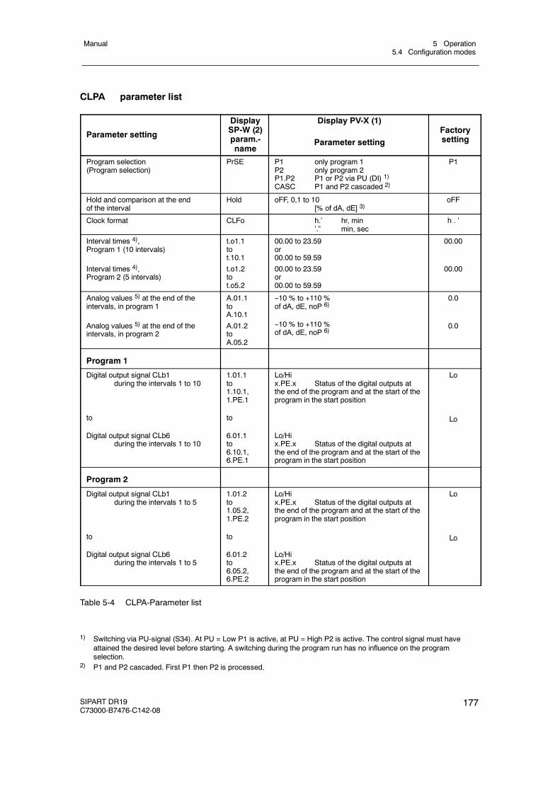
5 Operation5.4 Configuration modes
Manual
SIPART DR19C73000-B7476-C142-08
177
CLPA parameter list
Parameter setting
DisplaySP-W (2)param.-name
Display PV-X (1)
Parameter settingFactorysetting
Program selection(Program selection)
PrSE P1 only program 1P2 only program 2P1.P2 P1 or P2 via PU (DI) 1)CASC P1 and P2 cascaded 2)
P1
Hold and comparison at the endof the interval
Hold oFF, 0,1 to 10[% of dA, dE] 3)
oFF
Clock format CLFo h.’ hr, min’.” min, sec
h . ’
Interval times 4),Program 1 (10 intervals)
Interval times 4),Program 2 (5 intervals)
t.o1.1tot.10.1
t.o1.2tot.o5.2
00.00 to 23.59or00.00 to 59.59
00.00 to 23.59or00.00 to 59.59
00.00
00.00
Analog values 5) at the end of theintervals, in program 1
Analog values 5) at the end of theintervals, in program 2
A.01.1toA.10.1
A.01.2toA.05.2
--10 % to +110 %of dA, dE, noP 6)
--10 % to +110 %of dA, dE, noP 6)
0.0
0.0
Program 1
Digital output signal CLb1during the intervals 1 to 10
to
Digital output signal CLb6during the intervals 1 to 10
1.01.1to1.10.1,1.PE.1
to
6.01.1to6.10.1,6.PE.1
Lo/Hix.PE.x Status of the digital outputs atthe end of the program and at the start of theprogram in the start position
Lo/Hix.PE.x Status of the digital outputs atthe end of the program and at the start of theprogram in the start position
Lo
Lo
Program 2
Digital output signal CLb1during the intervals 1 to 5
to
Digital output signal CLb6during the intervals 1 to 5
1.01.2to1.05.2,1.PE.2
to
6.01.2to6.05.2,6.PE.2
Lo/Hix.PE.x Status of the digital outputs atthe end of the program and at the start of theprogram in the start position
Lo/Hix.PE.x Status of the digital outputs atthe end of the program and at the start of theprogram in the start position
Lo
Lo
Table 5-4 CLPA-Parameter list
1) Switching via PU-signal (S34). At PU = Low P1 is active, at PU = High P2 is active. The control signal must haveattained the desired level before starting. A switching during the program run has no influence on the programselection.
2) P1 and P2 cascaded. First P1 then P2 is processed.
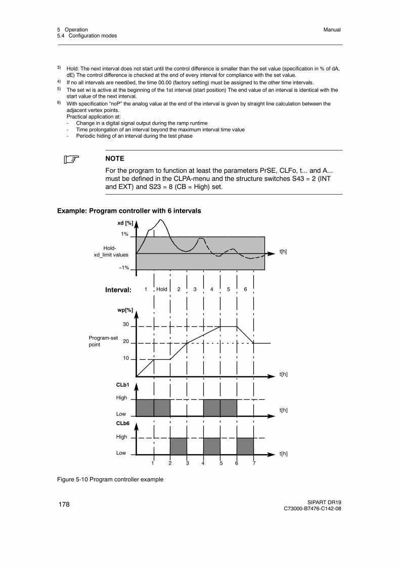
5 Operation5.4 Configuration modes
Manual
178 SIPART DR19C73000-B7476-C142-08
3) Hold: The next interval does not start until the control difference is smaller than the set value (specification in % of dA,dE) The control difference is checked at the end of every interval for compliance with the set value.
4) If no all intervals are needöed, the time 00.00 (factory setting) must be assigned to the other time intervals.5) The set wi is active at the beginning of the 1st interval (start position) The end value of an interval is identical with the
start value of the next interval.6) With specification “noP” the analog value at the end of the interval is given by straight line calculation between the
adjacent vertex points.Practical application at:- Change in a digital signal output during the ramp runtime- Time prolongation of an interval beyond the maximum interval time value- Periodic hiding of an interval during the test phase
. NOTE
For the program to function at least the parameters PrSE, CLFo, t... and A...must be defined in the CLPA-menu and the structure switches S43 = 2 (INTand EXT) and S23 = 8 (CB = High) set.
Example: Program controller with 6 intervals
xd [%]
Hold-xd_limit values
1%
--1%
t[h]
t[h]
t[h]
t[h]
wp[%]
10
20
30
High
Low
1 2 3 4 5 6 7
Interval: 1 2 3 4 5 6Hold
CLb1
CLb6
Program-setpoint
High
Low
Figure 5-10 Program controller example
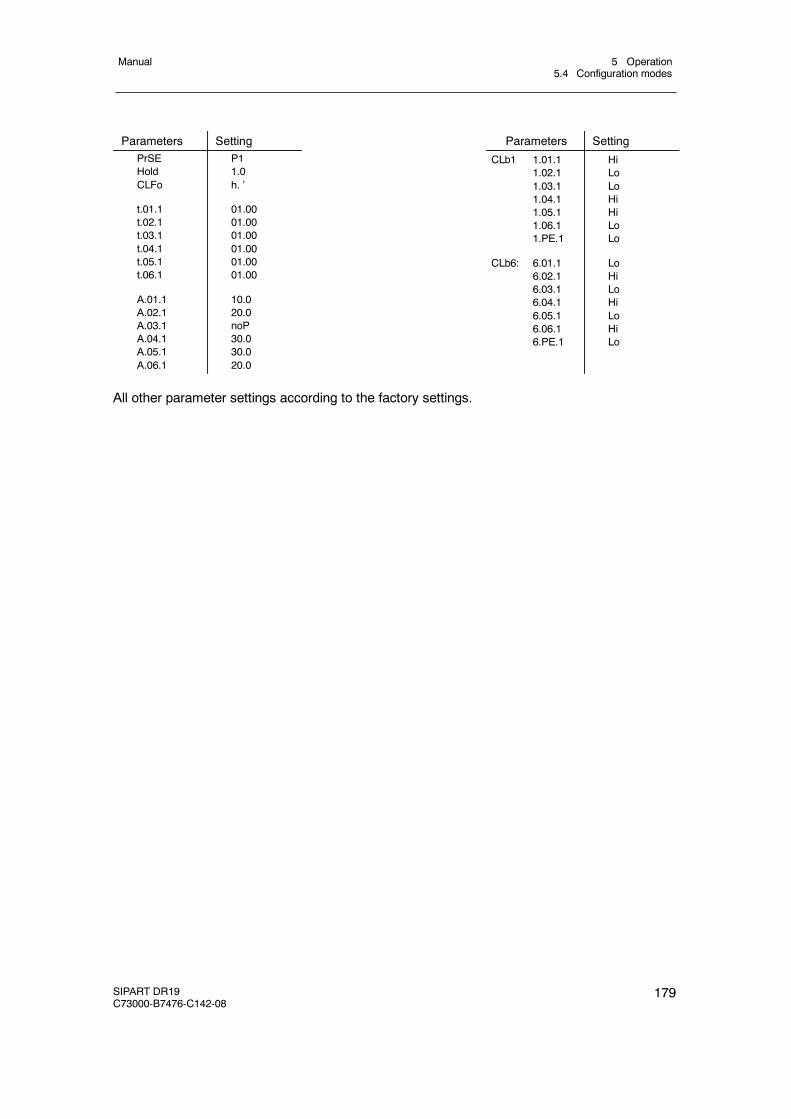
5 Operation5.4 Configuration modes
Manual
SIPART DR19C73000-B7476-C142-08
179
Parameters Setting Parameters SettingPrSEHoldCLFo
t.01.1t.02.1t.03.1t.04.1t.05.1t.06.1
A.01.1A.02.1A.03.1A.04.1A.05.1A.06.1
P11.0h. ’
01.0001.0001.0001.0001.0001.00
10.020.0noP30.030.020.0
CLb1
CLb6:
1.01.11.02.11.03.11.04.11.05.11.06.11.PE.1
6.01.16.02.16.03.16.04.16.05.16.06.16.PE.1
HiLoLoHiHiLoLo
LoHiLoHiLoHiLo
All other parameter settings according to the factory settings.
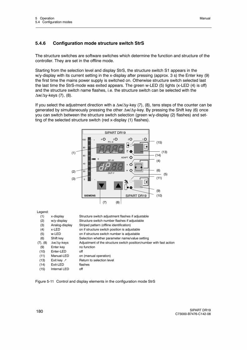
5 Operation5.4 Configuration modes
Manual
180 SIPART DR19C73000-B7476-C142-08
5.4.6 Configuration mode structure switch StrS
The structure switches are software switches which determine the function and structure of thecontroller. They are set in the offline mode.
Starting from the selection level and display StrS, the structure switch S1 appears in thew/y-display with its current setting in the x-display after pressing (approx. 3 s) the Enter key (9)the first time the mains power supply is switched on. Otherwise structure switch selected lastthe last time the StrS-mode was exited appears. The green w-LED (5) lights (x-LED (4) is off)and the structure switch name flashes, i.e. the structure switch can be selected with theΔw/Δy-keys (7), (8).
If you select the adjustment direction with a Δw/Δy-key (7), (8), tens steps of the counter can begenerated by simultaneously pressing the other Δw/Δy-key. By pressing the Shift key (6) onceyou can switch between the structure switch selection (green w/y-display (2) flashes) and set-ting of the selected structure switch (red x-display (1) flashes).
SIPART DR19
SIEMENS
OUT-Y
C
x
w
ADAPT
1234
SP--W
PV--X
SIPART DR19
100
80
0
20
40
60
+
--
0
(7) (8)
(1)
(2)
(3)
(10)(9)
(11)
(6)
(4)
(14)(13)
(15)
(5)
Legend:(1) x-display Structure switch adjustment flashes if adjustable(2) w/y-display Structure switch number flashes if adjustable(3) Analog-display Striped pattern (offline identification)(4) x-LED on if structure switch position is adjustable(5) w-LED on if structure switch number is adjustable(6) Shift key Selection whether parameter name/value setting
(7), (8) Δw/Δy-keys Adjustment of the structure switch position/number with fast action(9) Enter key no function(10) Enter-LED off(11) Manual-LED on (manual operation)(13) Exit key↗ Return to selection level(14) Exit-LED flashes(15) Internal LED off
Figure 5-11 Control and display elements in the configuration mode StrS
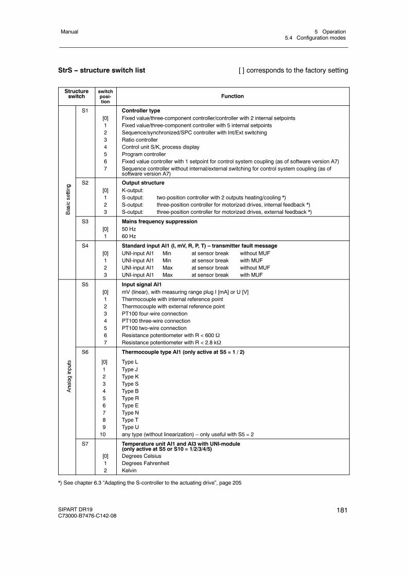
5 Operation5.4 Configuration modes
Manual
SIPART DR19C73000-B7476-C142-08
181
StrS -- structure switch list [ ] corresponds to the factory setting
Structureswitch
switchposi-tion
Function
S1 Controller type[0] Fixed value/three-component controller/controller with 2 internal setpoints1 Fixed value/three-component controller with 5 internal setpoints2 Sequence/synchronized/SPC controller with Int/Ext switching3 Ratio controller4 Control unit S/K, process display5 Program controller6 Fixed value controller with 1 setpoint for control system coupling (as of software version A7)7 Sequence controller without internal/external switching for control system coupling (as of
software version A7)
g S2 Output structure
etting
[0] K-output:
sett
1 S-output: two-position controller with 2 outputs heating/cooling *)
asics
2 S-output: three-position controller for motorized drives, internal feedback *)
Bas 3 S-output: three-position controller for motorized drives, external feedback *)B
S3 Mains frequency suppression[0] 50 Hz1 60 Hz
S4 Standard input AI1 (I, mV, R, P, T) – transmitter fault message[0] UNI-input AI1 Min at sensor break without MUF1 UNI-input AI1 Min at sensor break with MUF2 UNI-input AI1 Max at sensor break without MUF3 UNI-input AI1 Max at sensor break with MUF
S5 Input signal AI1[0] mV (linear), with measuring range plug I [mA] or U [V]1 Thermocouple with internal reference point2 Thermocouple with external reference point3 PT100 four-wire connection4 PT100 three-wire connection5 PT100 two-wire connection6 Resistance potentiometer with R < 600 Ω7 Resistance potentiometer with R < 2.8 kΩ
S6 Thermocouple type AI1 (only active at S5 = 1 / 2)
uts [0] Type L
input
1 Type J
ogin
2 Type K
nalo 3 Type S
An
4 Type B5 Type R6 Type E7 Type N8 Type T9 Type U10 any type (without linearization) – only useful with S5 = 2
S7 Temperature unit AI1 and AI3 with UNI-module(only active at S5 or S10 = 1/2/3/4/5)
[0] Degrees Celsius1 Degrees Fahrenheit2 Kelvin
*) See chapter 6.3 “Adapting the S-controller to the actuating drive”, page 205
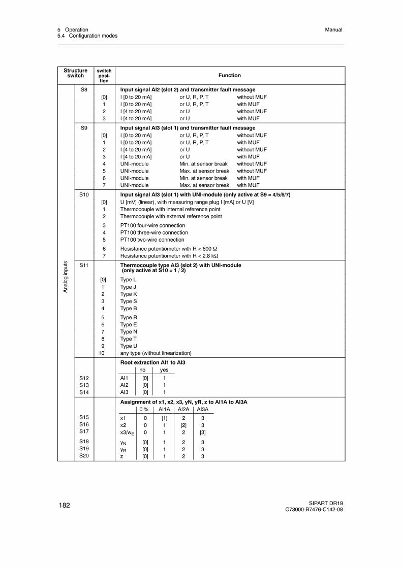
5 Operation5.4 Configuration modes
Manual
182 SIPART DR19C73000-B7476-C142-08
Structureswitch
switchposi-tion
Function
S8 Input signal AI2 (slot 2) and transmitter fault message[0] I [0 to 20 mA] or U, R, P, T without MUF1 I [0 to 20 mA] or U, R, P, T with MUF2 I [4 to 20 mA] or U without MUF3 I [4 to 20 mA] or U with MUF
S9 Input signal AI3 (slot 1) and transmitter fault message[0] I [0 to 20 mA] or U, R, P, T without MUF1 I [0 to 20 mA] or U, R, P, T with MUF2 I [4 to 20 mA] or U without MUF3 I [4 to 20 mA] or U with MUF4 UNI-module Min. at sensor break without MUF5 UNI-module Max. at sensor break without MUF6 UNI-module Min. at sensor break with MUF7 UNI-module Max. at sensor break with MUF
S10 Input signal AI3 (slot 1) with UNI-module (only active at S9 = 4/5/6/7)[0] U [mV] (linear), with measuring range plug I [mA] or U [V]1 Thermocouple with internal reference point2 Thermocouple with external reference point
3 PT100 four-wire connection4 PT100 three-wire connection5 PT100 two-wire connection
6 Resistance potentiometer with R < 600 Ω7 Resistance potentiometer with R < 2.8 kΩ
inputs S11 Thermocouple type AI3 (slot 2) with UNI-module
(only active at S10 = 1 / 2)
alog
in
[0] Type L
Analo
1 Type J
A 2 Type K3 Type S4 Type B
5 Type R6 Type E7 Type N8 Type T9 Type U10 any type (without linearization)
S12S13S14
Root extraction AI1 to AI3no yes
AI1 [0] 1AI2 [0] 1AI3 [0] 1
S15S16S17
S18S19S20
Assignment of x1, x2, x3, yN, yR, z to AI1A to AI3A0 % AI1A AI2A AI3A
x1 0 [1] 2 3x2 0 1 [2] 3x3/wE 0 1 2 [3]
yN [0] 1 2 3yR [0] 1 2 3z [0] 1 2 3
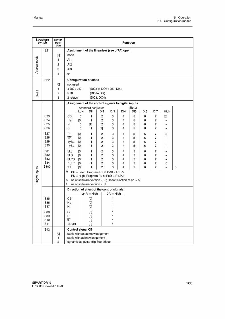
5 Operation5.4 Configuration modes
Manual
SIPART DR19C73000-B7476-C142-08
183
Structureswitch Function
switchposi-tion
S21 Assignment of the linearizer (see ofPA) open
ts
[0] none
nputs
1 AI1
ogin
2 AI2
Analo
3 AI3
An
4 x1
S22 Configuration of slot 3
[0] not used
3 1 4 DO / 2 DI (DO3 to DO6 / DI3, DI4)
Slot3 2 5 DI (DI3 to DI7)
Sl
3 2 relays (DO3, DO4)
Assignment of the control signals to digital inputs
puts
S23S24S25S26
S27S28S29S30
S31S32S33S34S100
Low DI1 DI2 DI3 DI4 DI5 DI6 DI7 High
CB 0 1 2 3 4 5 6 7 [8]He [0] 1 2 3 4 5 6 7 --N 0 [1] 2 3 4 5 6 7 --Si 0 1 [2] 3 4 5 6 7 --
P [0] 1 2 3 4 5 6 7 8tS2) [0] 1 2 3 4 5 6 7 --+yBL [0] 1 2 3 4 5 6 7 ----yBL [0] 1 2 3 4 5 6 7 --
bLb [0] 1 2 3 4 5 6 7 --bLS [0] 1 2 3 4 5 6 7 --bLPS [0] 1 2 3 4 5 6 7 --PU 1) [0] 1 2 3 4 5 6 7 8tSH [0] 1 2 3 4 5 6 7 --
Standard controller Slot 3
3)
Digitalinpu
1) PU = Low: Program P1 at PrSt = P1.P2PU = High: Program P2 at PrSt = P1.P2
2) as of software version --B6; Reset-function at S1 = 53) as of software version --B9
Direction of effect of the control signals
S35S36S37
S38S39S40S41
24 V = High 0 V = High
CB [0] 1He [0] 1N [0] 1
Si [0] 1P [0] 1tS [0] 1+/--yBL [0] 1
S42 Control signal CB[0] static without acknowledgement1 static with acknowledgement2 dynamic as pulse (flip-flop-effect)
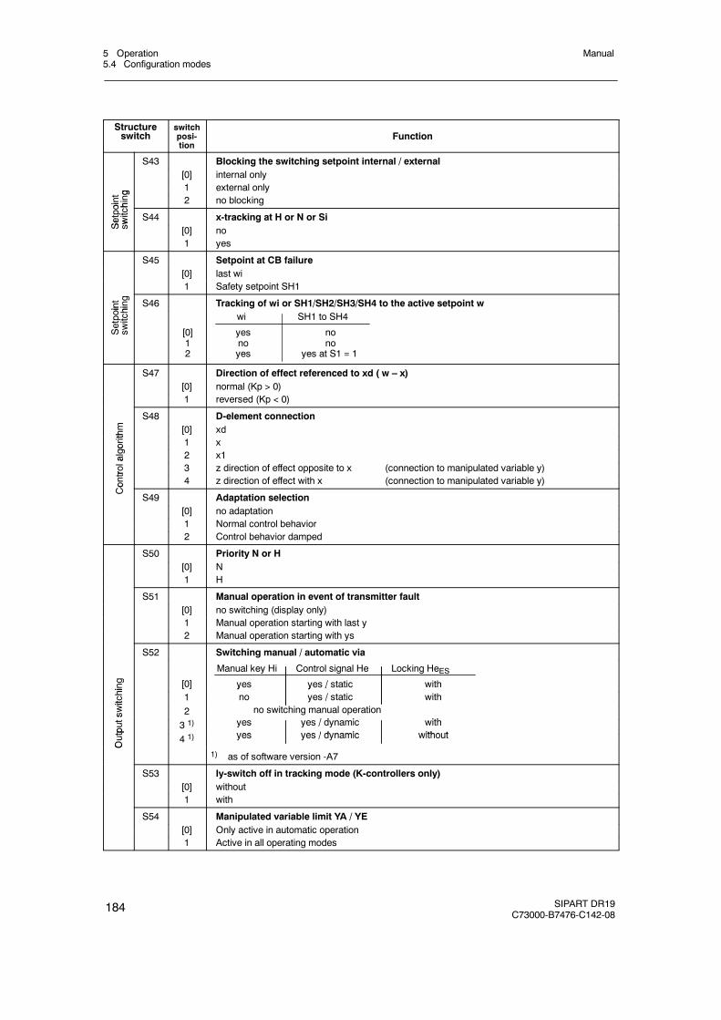
5 Operation5.4 Configuration modes
Manual
184 SIPART DR19C73000-B7476-C142-08
Structureswitch Function
switchposi-tion
S43 Blocking the switching setpoint internal / external[0] internal only
g 1 external only
oint hing 2 no blocking
Setpoi
switch
S44 x-tracking at H or N or Si
Se
sw [0] no1 yes
S45 Setpoint at CB failure[0] last wi1 Safety setpoint SH1
oint hing S46 Tracking of wi or SH1/SH2/SH3/SH4 to the active setpoint w
Setpoin
switchi
[0]12
wi SH1 to SH4
yes nono noyes yes at S1 = 1
S47 Direction of effect referenced to xd ( w – x)[0] normal (Kp > 0)1 reversed (Kp < 0)
m
S48 D-element connection
thm [0] xd
gorith
1 x
algo 2 x1
trola
3 z direction of effect opposite to x (connection to manipulated variable y)
Contr
4 z direction of effect with x (connection to manipulated variable y)
Co
S49 Adaptation selection[0] no adaptation1 Normal control behavior2 Control behavior damped
S50 Priority N or H[0] N1 H
S51 Manual operation in event of transmitter fault[0] no switching (display only)1 Manual operation starting with last y2 Manual operation starting with ys
S52 Switching manual / automatic via
hing [0]
Manual key Hi Control signal He Locking HeESyes yes / static with
witchi 1
y y /no yes / static with
swit
2y
no switching manual operation/ d i ith
tputs
3 1) yes yes / dynamic withyes yes / dynamic without
Outp
4 1) yes yes / dynamic without
O
1) as of software version -A7
S53 Iy-switch off in tracking mode (K-controllers only)[0] without1 with
S54 Manipulated variable limit YA / YE[0] Only active in automatic operation1 Active in all operating modes
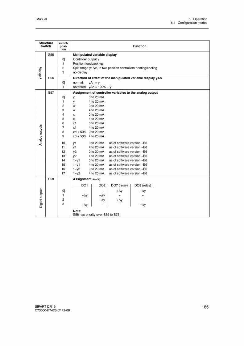
5 Operation5.4 Configuration modes
Manual
SIPART DR19C73000-B7476-C142-08
185
Structureswitch Function
switchposi-tion
S55 Manipulated variable display[0] Controller output y1 Position feedback yR
lay 2 Split range y1/y2, in two position controllers heating/cooling
ispla
3 no display
ydis
S56 Direction of effect of the manipulated variable display yAn[0] normal: yAn = y1 reversed: yAn = 100% -- y
S57 Assignment of controller variables to the analog output[0] y 0 to 20 mA1 y 4 to 20 mA2 w 0 to 20 mA3 w 4 to 20 mA4 x 0 to 20 mA5 x 4 to 20 mA
s 6 x1 0 to 20 mA
puts 7 x1 4 to 20 mA
outp 8 xd + 50% 0 to 20 mA
ogo
9 xd + 50% 4 to 20 mA
Analo
10 y1 0 to 20 mA as of software version --B6A
11 y1 4 to 20 mA as of software version --B612 y2 0 to 20 mA as of software version --B613 y2 4 to 20 mA as of software version --B614 1--y1 0 to 20 mA as of software version --B615 1--y1 4 to 20 mA as of software version --B616 1--y2 0 to 20 mA as of software version --B617 1--y2 4 to 20 mA as of software version --B6
S58 Assignment +/--Δy
Digitaloutputs [0]
123
DO1 DO2 DO7 (relay) DO8 (relay)
-- -- +Δy --Δy+Δy --Δy -- ---- --Δy +Δy --
+Δy -- -- --Δy
Note:S58 has priority over S59 to S75
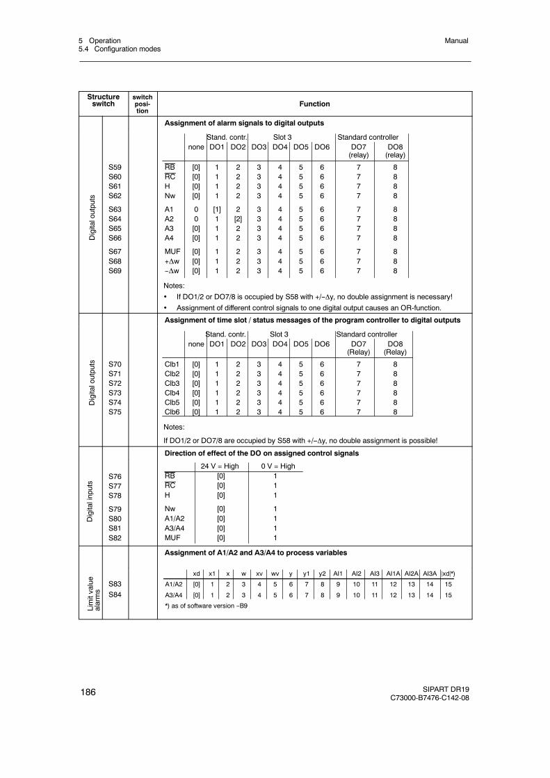
5 Operation5.4 Configuration modes
Manual
186 SIPART DR19C73000-B7476-C142-08
Structureswitch Function
switchposi-tion
Assignment of alarm signals to digital outputs
Digitaloutputs
S59S60S61S62
S63S64S65S66
S67S68S69
none DO1 DO2 DO3 DO4 DO5 DO6 DO7 DO8(relay) (relay)
RB [0] 1 2 3 4 5 6 7 8RC [0] 1 2 3 4 5 6 7 8H [0] 1 2 3 4 5 6 7 8Nw [0] 1 2 3 4 5 6 7 8
A1 0 [1] 2 3 4 5 6 7 8A2 0 1 [2] 3 4 5 6 7 8A3 [0] 1 2 3 4 5 6 7 8A4 [0] 1 2 3 4 5 6 7 8
MUF [0] 1 2 3 4 5 6 7 8+Δw [0] 1 2 3 4 5 6 7 8--Δw [0] 1 2 3 4 5 6 7 8
Notes:
If DO1/2 or DO7/8 is occupied by S58 with +/--y, no double assignment is necessary!
Assignment of different control signals to one digital output causes an OR-function.
Stand. contr. Slot 3 Standard controller
Assignment of time slot / status messages of the program controller to digital outputs
Digitaloutputs S70
S71S72S73S74S75
none DO1 DO2 DO3 DO4 DO5 DO6 DO7 DO8(Relay) (Relay)
Clb1 [0] 1 2 3 4 5 6 7 8Clb2 [0] 1 2 3 4 5 6 7 8Clb3 [0] 1 2 3 4 5 6 7 8Clb4 [0] 1 2 3 4 5 6 7 8Clb5 [0] 1 2 3 4 5 6 7 8Clb6 [0] 1 2 3 4 5 6 7 8
Notes:
If DO1/2 or DO7/8 are occupied by S58 with +/--y, no double assignment is possible!
Stand. contr. Slot 3 Standard controller
Direction of effect of the DO on assigned control signals
Digitalinputs
S76S77S78
S79S80S81S82
24 V = High 0 V = HighRB [0] 1RC [0] 1H [0] 1
Nw [0] 1A1/A2 [0] 1A3/A4 [0] 1MUF [0] 1
Assignment of A1/A2 and A3/A4 to process variables
Limitvalue
alarms
S83S84
xd x1 x w xv wv y y1 y2 AI1 AI2 AI3 AI1A AI2A AI3A jxdj*)
A1/A2 [0] 1 2 3 4 5 6 7 8 9 10 11 12 13 14 15
A3/A4 [0] 1 2 3 4 5 6 7 8 9 10 11 12 13 14 15
*) as of software version --B9
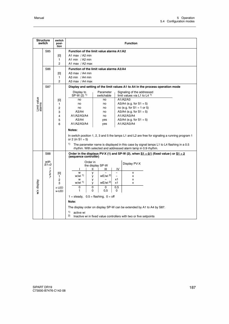
5 Operation5.4 Configuration modes
Manual
SIPART DR19C73000-B7476-C142-08
187
Structureswitch Function
switchposi-tion
S85 Function of the limit value alarms A1/A2[0] A1 max / A2 min1 A1 min / A2 min2 A1 max / A2 max
S86 Function of the limit value alarms A3/A4[0] A3 max / A4 min1 A3 min / A4 min2 A3 max / A4 max
S87 Display and setting of the limit values A1 to A4 in the process operation mode
Limitvalue
alarms
[0]123456
Display to Parameter Signaling of the addressedSP-W (2) 1) switchable limit values via L1 to L4 1)
no no A1/A2/A3no no A3/A4 (e.g. for S1 = 5)no no no (e.g. for S1 = 1 or 5)
A3/A4 no A3/A4 (e.g. for S1 = 5)A1/A2/A3/A4 no A1/A2/A3/A4
A3/A4 yes A3/A4 (e.g. for S1 = 5)A1/A2/A3/A4 yes A1/A2/A3/A4
Notes:
In switch position 1, 2, 3 and 5 the lamps L1 and L2 are free for signaling a running program 1or 2 (in S1 = 5)1) The parameter name is displayed in this case by signal lamps L1 to L4 flashing in a 0.5
rhythm. With selected and addressed alarm lamp in 0.9 rhythm.
S88 Order in the displays PV-X (1) and SP-W (2), when S1 = 0/1 (fixed value-) or S1 = 2(sequence controller)
w/xdisplay
withS1=0
1267
[0]123
x-LEDw-LED
Order inthe display SP-W
I II III IVw y -- -- x
w/wi 1) y wE/wi 2) -- xw y -- x1 x
w/wi 1) y wE/wi 2) x1 x0 0 0 0,51 0 0,5 0
Display PV-X
w
1 = steady, 0.5 = flashing, 0 = off
Note:
The display order on display SP-W can be extended by A1 to A4 by S87.1) active wi2) Inactive wi in fixed value controllers with two or five setpoints
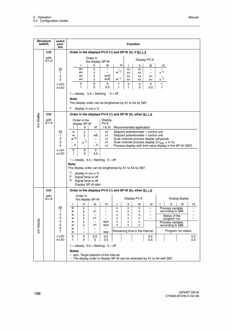
5 Operation5.4 Configuration modes
Manual
188 SIPART DR19C73000-B7476-C142-08
Structureswitch Function
switchposi-tion
S88 Order in the displays PV-X (1) and SP-W (2), if S1 = 3
withS1=3
[0]123
x-LEDw-LED
Order inthe display SP-W
I II III IVwv y -- --wv y -- w 1)
wv y wvEwv y wvE w 1)
0 0 0 11 0 0.5 1
I II III IVxv xv -- --xv xv -- x 1)
xv xv xv --xv xv xv x 1)
0 0 0 11 0 0.5 1
Display PV-X
1 = steady, 0.5 = flashing, 0 = off
Note:The display order can be lengthened by A1 to A4 by S87.
1) display in xxx.x %
play S88 Order in the displays PV-X (1) and SP-W (2), when S1 = 4
w/xdispla
withS1=4
[0]1234
x-LEDw-LED
I II III I to IIIw y -- x1w y wE x1w 2) -- -- x1-- y 1) -- x1-- 3) -- -- 3) x10 0 01 0 0,5
DisplayPV-X
Order in thedisplay SP-W
Recommended applicationSetpoint potentiometer + control unitSetpoint potentiometer + control unitDual--channel process display (physical)Dual--channel process display (x1phy, y in %)Process display with limit value display in the SP-W (S87)
1 = steady, 0.5 = flashing, 0 = offNote:The display order can be lengthened by A1 to A4 by S87.1) display in xxx.x %2) Signal lamp w off3) Signal lamp w off
Display SP-W dark
S88 Order in the displays PV-X (1) and SP-W (2), when S1 = 5
w/xdisplay
withS1=5
[0]1234567
x-LEDw-LED
Order inthe display SP-W
I II III IVw y -- --w y x1 --w y -- --w y x1 --w y -- wpzw y x1 wpzw -- -- --w -- -- wpz0 0 0.5 0.51 0 0 0.5
I II III IVx x x --x x x --x x x --x x x --x x xx x x
0.50.5
Display PV-X
I II III IV--------
0.50.5
Analog display
Process variable,according to S89
Status of theprogram run
Process variable,according to S89
Program run statusRemaining time in the interval
1 = steady, 0.5 = flashing, 0 = off
Notes:-- wpz: Target setpoint of the interval-- The display order in display SP-W can be extended by A1 to A4 with S87.
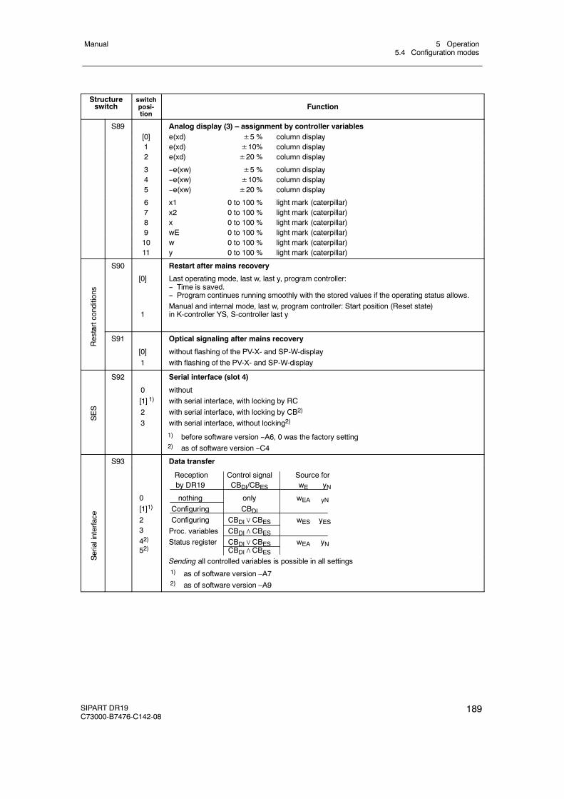
5 Operation5.4 Configuration modes
Manual
SIPART DR19C73000-B7476-C142-08
189
Structureswitch Function
switchposi-tion
S89 Analog display (3) – assignment by controller variables[0] e(xd) ±5 % column display1 e(xd) ±10% column display2 e(xd) ±20 % column display
3 --e(xw) ±5 % column display4 --e(xw) ±10% column display5 --e(xw) ±20 % column display
6 x1 0 to 100 % light mark (caterpillar)7 x2 0 to 100 % light mark (caterpillar)8 x 0 to 100 % light mark (caterpillar)9 wE 0 to 100 % light mark (caterpillar)10 w 0 to 100 % light mark (caterpillar)11 y 0 to 100 % light mark (caterpillar)
tartconditions
S90
[0]
1
Restart after mains recovery
Last operating mode, last w, last y, program controller:-- Time is saved.-- Program continues running smoothly with the stored values if the operating status allows.Manual and internal mode, last w, program controller: Start position (Reset state)in K-controller YS, S-controller last y
Resta
S91
[0]1
Optical signaling after mains recovery
without flashing of the PV-X- and SP-W-displaywith flashing of the PV-X- and SP-W-display
SES
S92
0[1] 1)
23
Serial interface (slot 4)
withoutwith serial interface, with locking by RCwith serial interface, with locking by CB2)
with serial interface, without locking2)
1) before software version --A6, 0 was the factory setting2) as of software version --C4
S93 Data transfer
Serialinterface
0[1]1)
2342)
52)
Reception Control signal Source forby DR19 CBDI/CBES wE yN
nothing only wEA yN
Configuring CBDIConfiguring CBDI∨CBES wES yESProc. variables CBDI∧CBESStatus register CBDI∨CBES wEA yN
CBDI∧CBES
Se
Sending all controlled variables is possible in all settings1) as of software version –A72) as of software version –A9
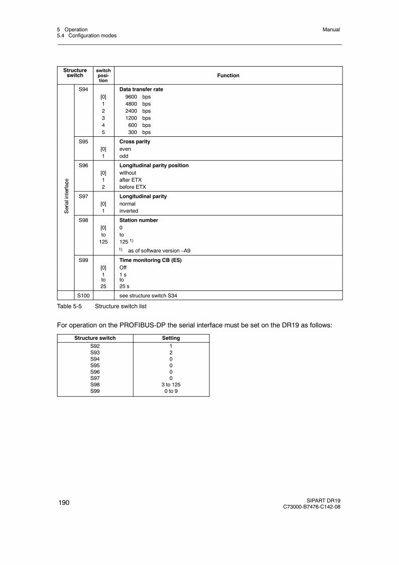
5 Operation5.4 Configuration modes
Manual
190 SIPART DR19C73000-B7476-C142-08
Structureswitch Function
switchposi-tion
S94 Data transfer rate[0] 9600 bps1 4800 bps2 2400 bps3 1200 bps4 600 bps5 300 bps
S95 Cross parity[0] even1 odd
S96 Longitudinal parity position[0] without
ce 1 after ETX
erfac
2 before ETX
linter
S97 Longitudinal parity
erial
[0] normal
Ser 1 invertedS
S98 Station number[0] 0to to125 125 1)
1) as of software version –A9
S99 Time monitoring CB (ES)[0] Off1to
1 sto
25 25 s
S100 see structure switch S34
Table 5-5 Structure switch list
For operation on the PROFIBUS-DP the serial interface must be set on the DR19 as follows:
Structure switch Setting
S92S93S94S95S96S97S98S99
120000
3 to 1250 to 9
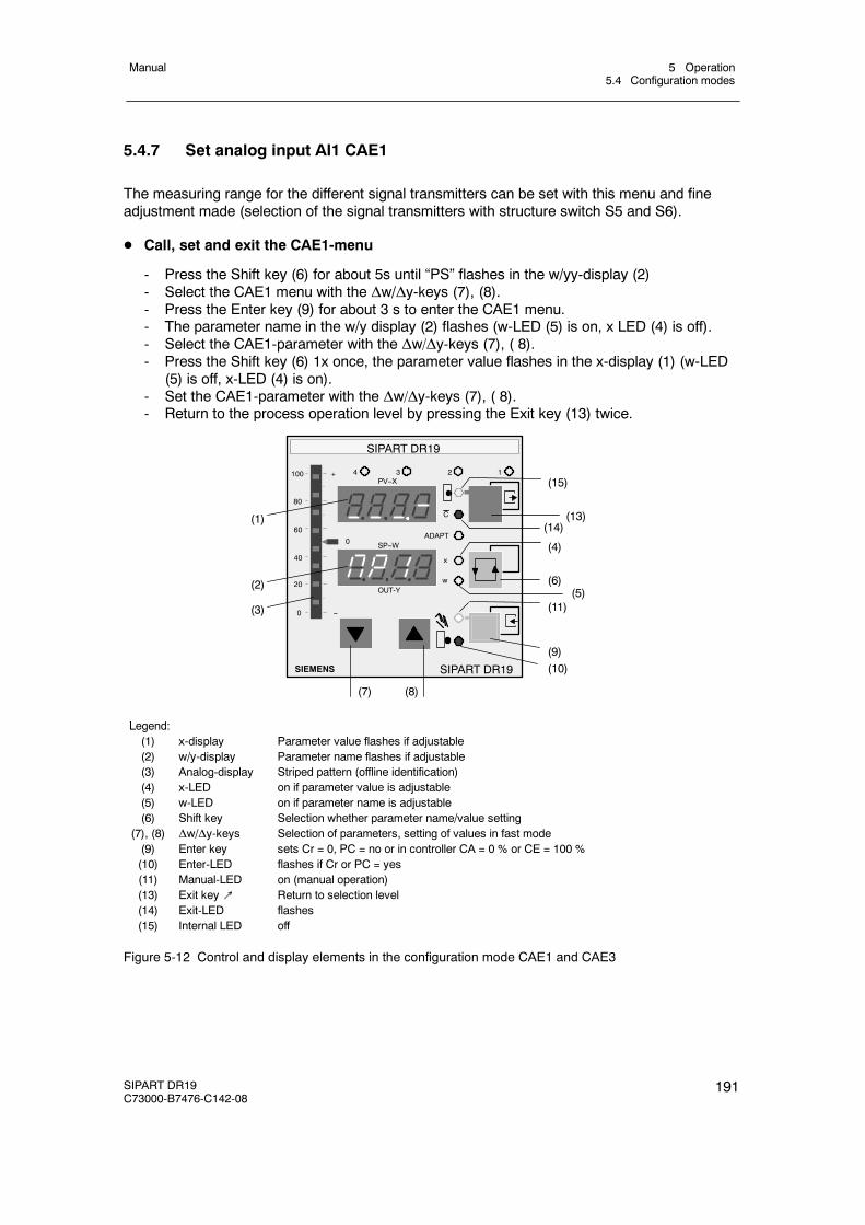
5 Operation5.4 Configuration modes
Manual
SIPART DR19C73000-B7476-C142-08
191
5.4.7 Set analog input AI1 CAE1
The measuring range for the different signal transmitters can be set with this menu and fineadjustment made (selection of the signal transmitters with structure switch S5 and S6).
D Call, set and exit the CAE1-menu
- Press the Shift key (6) for about 5s until “PS” flashes in the w/yy-display (2)- Select the CAE1 menu with the Δw/Δy-keys (7), (8).- Press the Enter key (9) for about 3 s to enter the CAE1 menu.- The parameter name in the w/y display (2) flashes (w-LED (5) is on, x LED (4) is off).- Select the CAE1-parameter with the Δw/Δy-keys (7), ( 8).- Press the Shift key (6) 1x once, the parameter value flashes in the x-display (1) (w-LED
(5) is off, x-LED (4) is on).- Set the CAE1-parameter with the Δw/Δy-keys (7), ( 8).- Return to the process operation level by pressing the Exit key (13) twice.
(1)
(2)
(3)
SIPART DR19
SIEMENS
OUT-Y
C
x
w
ADAPT
1234
SP--W
PV--X
SIPART DR19
(7) (8)
(10)(9)
(11)(5)
(6)
(4)
(14)(13)
(15)100
80
0
20
40
60
+
--
0
Legend:(1) x-display Parameter value flashes if adjustable(2) w/y-display Parameter name flashes if adjustable(3) Analog-display Striped pattern (offline identification)(4) x-LED on if parameter value is adjustable(5) w-LED on if parameter name is adjustable(6) Shift key Selection whether parameter name/value setting
(7), (8) Δw/Δy-keys Selection of parameters, setting of values in fast mode(9) Enter key sets Cr = 0, PC = no or in controller CA = 0 % or CE = 100 %(10) Enter-LED flashes if Cr or PC = yes(11) Manual-LED on (manual operation)(13) Exit key↗ Return to selection level(14) Exit-LED flashes(15) Internal LED off
Figure 5-12 Control and display elements in the configuration mode CAE1 and CAE3
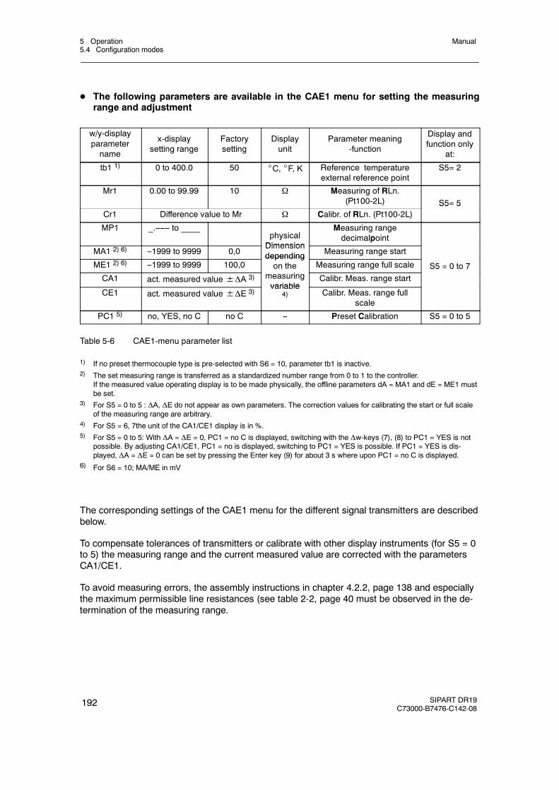
5 Operation5.4 Configuration modes
Manual
192 SIPART DR19C73000-B7476-C142-08
D The following parameters are available in the CAE1 menu for setting the measuringrange and adjustment
w/y-displayparametername
x-displaysetting range
Factorysetting
Displayunit
Parameter meaning-function
Display andfunction only
at:
tb1 1) 0 to 400.0 50 _C, _F, K Reference temperatureexternal reference point
S5= 2
Mr1 0.00 to 99.99 10 Ω Measuring of RLn.(Pt100-2L) S5= 5
Cr1 Difference value to Mr Ω Calibr. of RLn. (Pt100-2L)S5 5
MP1 _.------ to ____physicalDimension
Measuring rangedecimalpoint
MA1 2) 6) --1999 to 9999 0,0Dimensiondepending Measuring range start
ME1 2) 6) --1999 to 9999 100,0dependingon the Measuring range full scale S5 = 0 to 7
CA1 act. measured value±ΔA 3) measuringvariable
Calibr. Meas. range start
CE1 act. measured value±ΔE 3)variable
4) Calibr. Meas. range fullscale
PC1 5) no, YES, no C no C -- Preset Calibration S5 = 0 to 5
Table 5-6 CAE1-menu parameter list
1) If no preset thermocouple type is pre-selected with S6 = 10, parameter tb1 is inactive.2) The set measuring range is transferred as a standardized number range from 0 to 1 to the controller.
If the measured value operating display is to be made physically, the offline parameters dA = MA1 and dE = ME1 mustbe set.
3) For S5 = 0 to 5 : ΔA, ΔE do not appear as own parameters. The correction values for calibrating the start or full scaleof the measuring range are arbitrary.
4) For S5 = 6, 7the unit of the CA1/CE1 display is in %.5) For S5 = 0 to 5: With ΔA = ΔE = 0, PC1 = no C is displayed, switching with the Δw-keys (7), (8) to PC1 = YES is not
possible. By adjusting CA1/CE1, PC1 = no is displayed, switching to PC1 = YES is possible. If PC1 = YES is dis-played, ΔA = ΔE = 0 can be set by pressing the Enter key (9) for about 3 s where upon PC1 = no C is displayed.
6) For S6 = 10; MA/ME in mV
The corresponding settings of the CAE1 menu for the different signal transmitters are describedbelow.
To compensate tolerances of transmitters or calibrate with other display instruments (for S5 = 0to 5) the measuring range and the current measured value are corrected with the parametersCA1/CE1.
To avoid measuring errors, the assembly instructions in chapter 4.2.2, page 138 and especiallythe maximum permissible line resistances (see table 2-2, page 40 must be observed in the de-termination of the measuring range.
5 Operation5.4 Configuration modes
Manual
SIPART DR19C73000-B7476-C142-08
193
5.4.7.1 Measuring range for mV (S5 = 0)
D MA1/ME1 -- set measuring range
Call parameter MA1, ME1, set measuring range start band end:Measuring range limits -175 mV≤MA1≤ME1≤+175 mV
D CA1/CE1 – fine adjustment
Call parameter CA1,set signal to start of scale,correct the display with CA1 if necessary.
Call parameter CE1,set signal to full scale,correct the display with CE1 if necessary.
5.4.7.2 Measuring range for U, I (S5 = 0)only with measuring range plug 6DR2805-8J
D MA1/ME1 -- set measuring range
Call parameter MA1, ME1, set measuring range start and end:Measuring range limits -175 mV≤MA1≤ME1≤+175 mV
Initialization in the measuring range plug
0 to 10 V or 0 to 20 mA signal corresponds to MA1 = 0 mV ME1 = 100 mV2 to 10 V or 4 to 20 mA signal corresponds to MA1 = 20 mV ME1 = 100 mV
D CA/CE fine adjustment
Call parameter CA1,set signal to start of scale,correct the display with CA1 if necessary.
Call parameter CE1,set signal to full scale,correct the display with CE1 if necessary.
5.4.7.3 Measuring range for thermocouple with internal reference point (S5 = 1)
D MA1/ME1 -- set measuring range
Call parameters MA1, ME1, start of scale and full scale according to the thermocouple type(S6) and the temperature unit (S7).
5 Operation5.4 Configuration modes
Manual
194 SIPART DR19C73000-B7476-C142-08
D CA1/CE1 – fine adjustment
Call parameter CA1,set signal to start of scale,correct the display with CA1 if necessary.
Call parameter CE1,set signal to full scale,correct the display with CE1 if necessary.
5.4.7.4 Measuring range for thermocouple with internal reference point (S5 = 2)
D tb1 – external reference points-temperature
Set the external reference point temperature with tb1. Preset temperature unit with S7.Attention: tb1 has no effect at S6 = 10!
D Set MA1 – ME1 measuring range
Call parameters MA1, ME1, start of scale and full scale according to the thermocouple type(S6) and the temperature unit.
D CA1/CE1 – fine adjustment (only if required)
Call parameter CA1,set signal to start of scale,correct the display with CA1 if necessary.
Call parameter CE1,set signal to full scale,correct the display with CE1 if necessary.
5.4.7.5 Measuring range for PT100 four-wire and three-wire connection(S5 = 3, 4)
D MA1/ME1 -- set measuring range
Call parameter MA1, ME1, set measuring range start and end:Measuring range limits -200 _C≤MA1≤ME1≤+850 _C
Preset temperature unit with S7.
D CA1/CE1 – fine adjustment (only if required)
Call parameter CA1,set signal to start of scale,correct the display with CA1 if necessary.
Call parameter CE1,set signal to full scale,correct the display with CE1 if necessary.
5 Operation5.4 Configuration modes
Manual
SIPART DR19C73000-B7476-C142-08
195
5.4.7.6 Measuring range for PT100 two-wire connection (S5 = 5)
D MR1/CR1 adjustment of the supply lead resistor
Path 1: The feed line resistance is known.- Enter the known resistance value with parameter MR1- CR1 is ignored
Path 2: The feed line resistance is not known.- Short circuit PT100- sensor at the measuring point- Call parameter CR1 and press the Enter key (9) until 0.00 Ω
is displayed- MR1 indicates the measured resistance value
D Set MA1 – ME1 measuring range
Call parameter MA1, ME1, set measuring range start and end:Measuring range limits -200 _C≤MA1≤ME1≤+850 _C
Preset temperature unit with S7.
D CA1/CE1 – fine adjustment
Call parameter CA1,set signal to start of scale,correct the display with CA1 if necessary.
Call parameter CE1,set signal to full scale,correct the display with CE1 if necessary.
5.4.7.7 Measuring range for resistance potentiometer (S5 = 6, 7)
Path 1 : The start and end values of the R-potentiometer are known.
- Call parameter MA1, ME1set start of scale and full scale:0 Ω≤MA1≤ME1≤600 Ω / 2,8 kΩ
- Parameters CA1/CE1 indicate at R = MA1 0% , at R = ME1 100 %.For the three-wire connection applies: R = Rp+ RL4For the four-wire connection applies: R = Rp+ RL1 + RL4
Path 2 : The start and end values of the R-potentiometer are not known.
- Call parameter CA1,Move final control element to position 0 %, press the Enter key (9) until 0.0 %is displayed.
- Call parameter CE1,Move final control element to position 100 %, press the Enter key until 100.0 %is displayed.
- Parameters MA1/ME1 indicate the appropriate resistance values.- MP1 must be set so that the range is not exceeded (x-display (1): oFL)
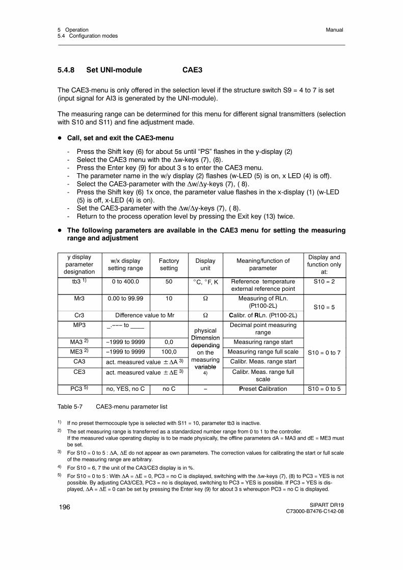
5 Operation5.4 Configuration modes
Manual
196 SIPART DR19C73000-B7476-C142-08
5.4.8 Set UNI-module CAE3
The CAE3-menu is only offered in the selection level if the structure switch S9 = 4 to 7 is set(input signal for AI3 is generated by the UNI-module).
The measuring range can be determined for this menu for different signal transmitters (selectionwith S10 and S11) and fine adjustment made.
D Call, set and exit the CAE3-menu
- Press the Shift key (6) for about 5s until “PS” flashes in the y-display (2)- Select the CAE3 menu with the Δw-keys (7), (8).- Press the Enter key (9) for about 3 s to enter the CAE3 menu.- The parameter name in the w/y display (2) flashes (w-LED (5) is on, x LED (4) is off).- Select the CAE3-parameter with the Δw/Δy-keys (7), ( 8).- Press the Shift key (6) 1x once, the parameter value flashes in the x-display (1) (w-LED
(5) is off, x-LED (4) is on).- Set the CAE3-parameter with the Δw/Δy-keys (7), ( 8).- Return to the process operation level by pressing the Exit key (13) twice.
D The following parameters are available in the CAE3 menu for setting the measuringrange and adjustment
y displayparameterdesignation
w/x displaysetting range
Factorysetting
Displayunit
Meaning/function ofparameter
Display andfunction only
at:
tb3 1) 0 to 400.0 50 _C, _F, K Reference temperatureexternal reference point
S10 = 2
Mr3 0.00 to 99.99 10 Ω Measuring of RLn.(Pt100-2L) S10 = 5
Cr3 Difference value to Mr Ω Calibr. of RLn. (Pt100-2L)S10 5
MP3 _.------ to ____physicalDimension
Decimal point measuringrange
MA3 2) --1999 to 9999 0,0Dimensiondepending Measuring range start
ME3 2) --1999 to 9999 100,0dependingon the Measuring range full scale S10 = 0 to 7
CA3 act. measured value±ΔA 3) measuringvariable
Calibr. Meas. range start
CE3 act. measured value±ΔE 3)variable
4) Calibr. Meas. range fullscale
PC3 5) no, YES, no C no C -- Preset Calibration S10 = 0 to 5
Table 5-7 CAE3-menu parameter list
1) If no preset thermocouple type is selected with S11 = 10, parameter tb3 is inactive.2) The set measuring range is transferred as a standardized number range from 0 to 1 to the controller.
If the measured value operating display is to be made physically, the offline parameters dA = MA3 and dE = ME3 mustbe set.
3) For S10 = 0 to 5 : ΔA, ΔE do not appear as own parameters. The correction values for calibrating the start or full scaleof the measuring range are arbitrary.
4) For S10 = 6, 7 the unit of the CA3/CE3 display is in %.5) For S10 = 0 to 5 : With ΔA = ΔE = 0, PC3 = no C is displayed, switching with the Δw-keys (7), (8) to PC3 = YES is not
possible. By adjusting CA3/CE3, PC3 = no is displayed, switching to PC3 = YES is possible. If PC3 = YES is dis-played, ΔA = ΔE = 0 can be set by pressing the Enter key (9) for about 3 s whereupon PC3 = no C is displayed.
5 Operation5.4 Configuration modes
Manual
SIPART DR19C73000-B7476-C142-08
197
Control and display elements in the configuration level CAE3, see figure 5-12, page 191
The corresponding settings of the CAE3 menu for the different signal transmitters are describedbelow.
To compensate tolerances of transmitters or calibrate with other display instruments (for S10 =0 to 5) the measuring range and the current measured value are corrected with the parametersCA3/CE3.
5.4.8.1 Measuring range for mV (S10 = 0)
D MA3/ME3 – set measuring range
Call parameter MA3, ME3, set start of scale and full scale:Measuring range limits -175 mV≤MA3≤ME3≤+175 mV
D CA3/CE3 – fine adjustment (only if required)
Call parameter CA3,set signal to start of scale,correct the display with CA3 if necessary.
Call parameter CE3,set signal to full scale,correct the display with CE3 if necessary.
5.4.8.2 Measuring range for U, I (S10 = 0)only with measuring range plug 6DR2805-8J
D MA3/ME3 – set measuring range
Call parameter MA3, ME3, set start of scale and full scale:Measuring range limits -175 mV≤MA3≤ME3≤+175 mV
Initialization in the measuring range plug:
0 to 10 V or 0 to 20 mA signal corresponds to MA3 = 0 mV ME3 = 100 mV2 to 10 V or 4 to 20 mA signal corresponds to MA3 = 20 mV ME3 = 100 mV
D CA3/CE3 – fine adjustment (only if required)
Call parameter CA3,set signal to start of scale,correct the display with CA3 if necessary.
Call parameter CE3,set signal to full scale,correct the display with CE3 if necessary.
5 Operation5.4 Configuration modes
Manual
198 SIPART DR19C73000-B7476-C142-08
5.4.8.3 Measuring range for thermocouple with internal reference point(S10 = 1)
D MA3/ME3 – set measuring range
Call parameters MA3, ME3, start of scale and full scale according to the thermocouple type(S11) and the temperature unit (S7).
D CA3/CE3 – fine adjustment
Call parameter CA3,set signal to start of scale,correct the display with CA3 if necessary.
Call parameter CE3,set signal to full scale,correct the display with CE3 if necessary.
5.4.8.4 Measuring range for thermocouple with internal reference point(S10 = 2)
D tb3 – external reference points-temperature
Set the external reference point temperature with tb3. Preset temperature unit with S7.Attention: tb3 has no effect at S11 = 10!
D MA3/ME3 – set measuring range
Call parameters MA3, ME3, start of scale and full scale according to the thermocouple type(S11) and the temperature unit.
D CA3/CE3 – fine adjustment
Call parameter CA3,set signal to start of scale,correct the display with CA3 if necessary.
Call parameter CE3,set signal to full scale,correct the display with CE3 if necessary.
5 Operation5.4 Configuration modes
Manual
SIPART DR19C73000-B7476-C142-08
199
5.4.8.5 Measuring range for PT100 four-wire and three-wire connection(S10 = 3, 4)
D MA3/ME3 – set measuring range
Call parameter MA3, ME3, set start of scale and full scale:Measuring range limits -200 _C≤MA3≤ME3≤+850 _C
Preset temperature unit with S7.
D CA3/CE3 – fine adjustment (only if required)
Call parameter CA3,set signal to start of scale,correct the display with CA3 if necessary.
Call parameter CE3,set signal to full scale,correct the display with CE3 if necessary.
5.4.8.6 Measuring range for PT100 two-wire connection (S10 = 5)
D MR3/CR3-adjustment of the feed resistance
Path 1: The feed line resistance is known.
- Enter the known resistance value with parameter MR3- CR3 is ignored
Path 2: The feed line resistance is not known.
- Short circuit PT100- sensor at the measuring point- Call parameter CR3 and press the Enter key (9) until 0.00 Ω
is displayed- MR3 indicates the measured resistance value
D MA3/ME3 – set measuring range
Call parameter MA3, ME3, set start of scale and full scale:Measuring range limits -200 _C≤MA3≤ME3≤+850 _C
Preset temperature unit with S7.
D CA3/CE3 – fine adjustment (only if required)
Call parameter CA3,set signal to start of scale,correct the display with CA3 if necessary.
Call parameter CE3,set signal to full scale,correct the display with CE3 if necessary.
5 Operation5.4 Configuration modes
Manual
200 SIPART DR19C73000-B7476-C142-08
5.4.8.7 Measuring range for resistance potentiometer (S10 = 6, 7)
Path 1 : The start and end values of the R-potentiometer are known.
- Call parameter MA3, ME3, set start of scale and full scale:0 Ω≤MA3≤ME3≤600 Ω / 2.8 kΩ
- Parameters CA3/CE3 indicate at R = MA3 0% , at R = ME3 100 %.For the three-wire connection applies: R = Rp+ RL4For the three-wire connection applies: R = Rp+ RL1 + RL4
Path 2 : The start and end values of the R-potentiometer are not known.
- Call parameter CA3 ,Move final control element to position 0 %, press the Enter key (9) until 0.0 %is displayed.
- Call parameter CE3 ,Move final control element to position 100 %, press the Enter key until 100.0 %is displayed.
- Parameters MA3/ME3 indicate the appropriate resistance values.- MP3 must be set so that the range is not exceeded (x-display (1): oFL)
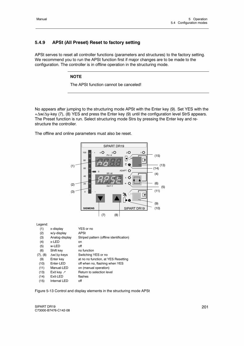
5 Operation5.4 Configuration modes
Manual
SIPART DR19C73000-B7476-C142-08
201
5.4.9 APSt (All Preset) Reset to factory setting
APSt serves to reset all controller functions (parameters and structures) to the factory setting.We recommend you to run the APSt function first if major changes are to be made to theconfiguration. The controller is in offline operation in the structuring mode.
NOTE
The APSt function cannot be canceled!
No appears after jumping to the structuring mode APSt with the Enter key (9). Set YES with the+Δw/Δy-key (7), (8) YES and press the Enter key (9) until the configuration level StrS appears.The Preset function is run. Select structuring mode Strs by pressing the Enter key and re-structure the controller.
The offline and online parameters must also be reset.
(1)
(2)
(3)
SIPART DR19
SIEMENS
OUT-Y
C
x
w
ADAPT
1234
SP--W
PV--X
SIPART DR19
(7) (8)
(10)(9)
(11)(5)
(6)
(4)
(14)(13)
(15)100
80
0
20
40
60
+
--
0
Legend:(1) x-display YES or no(2) w/y-display APSt(3) Analog-display Striped pattern (offline identification)(4) x-LED on(5) w-LED off(6) Shift key no function
(7), (8) Δw/Δy-keys Switching YES or no(9) Enter key at no no function, at YES Resetting(10) Enter-LED off when no, flashing when YES(11) Manual-LED on (manual operation)(13) Exit key↗ Return to selection level(14) Exit-LED flashes(15) Internal LED off
Figure 5-13 Control and display elements in the structuring mode APSt
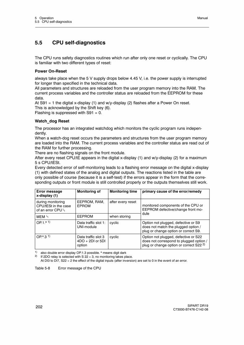
5 Operation5.5 CPU self-diagnostics
Manual
202 SIPART DR19C73000-B7476-C142-08
5.5 CPU self-diagnostics
The CPU runs safety diagnostics routines which run after only one reset or cyclically. The CPUis familiar with two different types of reset:
Power On-Reset
always take place when the 5 V supply drops below 4.45 V, i.e. the power supply is interruptedfor longer than specified in the technical data.All parameters and structures are reloaded from the user program memory into the RAM. Thecurrent process variables and the controller status are reloaded from the EEPROM for thesedata.At S91 = 1 the digital x-display (1) and w/y-display (2) flashes after a Power On reset.This is acknowledged by the Shift key (6).Flashing is suppressed with S91 = 0.
Watch_dog Reset
The processor has an integrated watchdog which monitors the cyclic program runs indepen-dently.When a watch-dog reset occurs the parameters and structures from the user program memoryare loaded into the RAM. The current process variables and the controller status are read out ofthe RAM for further processing.There are no flashing signals on the front module.After every reset CPU/tE appears in the digital x-display (1) and w/y-display (2) for a maximum5 s CPU/tESt.Every detected error of self-monitoring leads to a flashing error message on the digital x-display(1) with defined states of the analog and digital outputs. The reactions listed in the table areonly possible of course (because it is a self-test) if the errors appear in the form that the corre-sponding outputs or front module is still controlled properly or the outputs themselves still work.
Error messagex-display (1)
Monitoring of Monitoring time primary cause of the error/remedy
during monitoringCPU/tESt in the caseof an error CPU
EEPROM, RAM,EPROM
after every resetmonitored components of the CPU orEEPROM defective/change front mo-dule
MEM EEPROM when storingdule
OP.1.* 1) Data traffic slot 1:UNI-module
cyclic Option not plugged, defective or S9does not match the plugged option /plug or change option or correct S9.
OP.*.3 1) Data traffic slot 34DO + 2DI or 5DIoption
cyclic Option not plugged, defective or S22does not correspond to plugged option /plug or change option or correct S22 2)
1) also double error display OP.1.3 possible. * means digit dark2) If 2DO relay is selected with S 22 = 3, no monitoring takes place.
At DI3 to DI7, S22 = 2 the effect of the digital inputs (after inversion) are set to 0 in the event of an error.
Table 5-8 Error message of the CPU
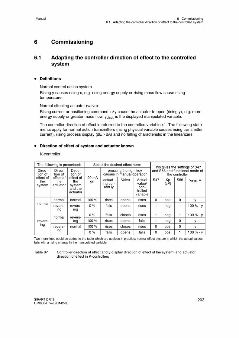
6 Commissioning6.1 Adapting the controller direction of effect to the controlled system
Manual
SIPART DR19C73000-B7476-C142-08
203
6 Commissioning
6.1 Adapting the controller direction of effect to the controlledsystem
D Definitions
Normal control action systemRising y causes rising x, e.g. rising energy supply or rising mass flow cause risingtemperature.
Normal effecting actuator (valve):Rising current or positioning command +y cause the actuator to open (rising y), e.g. moreenergy supply or greater mass flow. ydispl. is the displayed manipulated variable.
The controller direction of effect is referred to the controlled variable x1. The following state-ments apply for normal action transmitters (rising physical variable causes rising transmittercurrent), rising process display (dE>dA) and no falling characteristic in the linearizers.
D Direction of effect of system and actuator known
K-controller
The following is prescribed: Select the desired effect here:This gives the settings of S47
Direc-tion offf t f
Direc-tion offf t f
Direc-tion offf t f 20 A
pressing the right keycauses in manual operation
This gives the settings of S47and S56 and functional mode of
the controllert o oeffect ofthe
system
t o oeffect ofthe
actuator
t o oeffect ofthe
systemand theactuator
20 mAon actuat-
ing cur-rent ly
Valve Actualvalue/con-trolledvariable
S47 Kp(cP)
S56 ydispl. =
lnormal normal 100 % rises opens rises 0 pos. 0 y
normal revers-ing
revers-ing
0 % falls opens rises 1 neg. 1 100 % - y
normal revers-0 % falls closes rises 1 neg. 1 100 % - y
revers-i
normal revers-ing 100 % rises opens falls 1 neg. 0 yrevers
ing revers-i
normal 100 % rises closes rises 0 pos. 0 ying 0 % falls opens falls 0 pos. 1 100 % - y
Two more lines could be added to the table which are useless in practice: normal effect system in which the actual valuesfalls with a rising change in the manipulated variable.
Table 6-1 Controller direction of effect and y-display direction of effect of the system- and actuatordirection of effect in K-controllers
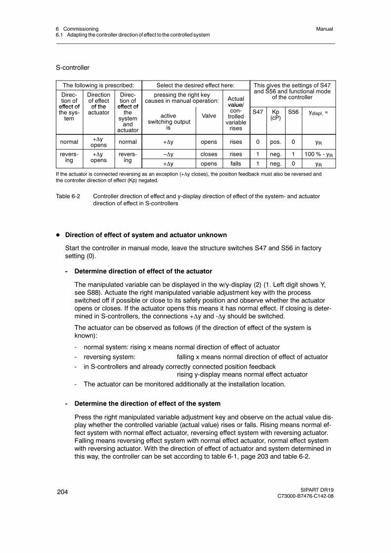
6 Commissioning6.1 Adapting the controller direction of effect to the controlledsystem
Manual
204 SIPART DR19C73000-B7476-C142-08
S-controller
The following is prescribed: Select the desired effect here: This gives the settings of S47d S56 d f ti l dDirec-
tion ofeffect of
Directionof effectof the
Direc-tion ofeffect of
pressing the right keycauses in manual operation: Actual
value/
g gand S56 and functional mode
of the controller
effect ofthe sys-tem
of theactuator
effect ofthe
systemand
actuator
activeswitching output
is
Valve
value/con-trolledvariablerises
S47 Kp(cP)
S56 ydispl. =
normal +yopens normal +y opens rises 0 pos. 0 yR
revers-i
+y revers-i
--y closes rises 1 neg. 1 100 % - yRing
yopens ing +y opens falls 1 neg. 0 yR
If the actuator is connected reversing as an exception (+y closes), the position feedback must also be reversed andthe controller direction of effect (Kp) negated.
Table 6-2 Controller direction of effect and y-display direction of effect of the system- and actuatordirection of effect in S-controllers
D Direction of effect of system and actuator unknown
Start the controller in manual mode, leave the structure switches S47 and S56 in factorysetting (0).
- Determine direction of effect of the actuator
The manipulated variable can be displayed in the w/y-display (2) (1. Left digit shows Y,see S88). Actuate the right manipulated variable adjustment key with the processswitched off if possible or close to its safety position and observe whether the actuatoropens or closes. If the actuator opens this means it has normal effect. If closing is deter-mined in S-controllers, the connections +y and -y should be switched.
The actuator can be observed as follows (if the direction of effect of the system isknown):
- normal system: rising x means normal direction of effect of actuator- reversing system: falling x means normal direction of effect of actuator- in S-controllers and already correctly connected position feedback
rising y-display means normal effect actuator- The actuator can be monitored additionally at the installation location.
- Determine the direction of effect of the system
Press the right manipulated variable adjustment key and observe on the actual value dis-play whether the controlled variable (actual value) rises or falls. Rising means normal ef-fect system with normal effect actuator, reversing effect system with reversing actuator.Falling means reversing effect system with normal effect actuator, normal effect systemwith reversing actuator. With the direction of effect of actuator and system determined inthis way, the controller can be set according to table 6-1, page 203 and table 6-2.
6 Commissioning6.2 Setting of actuating time in K-controllers (S2 = 0)
Manual
SIPART DR19C73000-B7476-C142-08
205
6.2 Setting of actuating time in K-controllers (S2 = 0)
D Actuating time tP, tM
Set the actuating time tP (open) or tM (closed) to the actuating time of the following actuator. Ifthe control circuit is to be settled additionally, e.g. to avoid hard impact on the actuating drive,tP, tM can be further increased in automatic operation.
The value of tP is usually set identical to the value of tM.
6.3 Adaptation of the S-controller to the actuating drive
D Output Two-position controller for heating/cooling (S2 = 1)
The setting range y can be divided into two sections. The offline-parameters Y1 and Y2 andthe online-parameters YA and YE determine these steps.
The period duration and the shortest turn-on and turn-off times are determined in the coolingbranch (section [YA, Y1]) by the online -parameters tM and tA and in the heating branch(section [Y2, YE]) by the online-parameters tP and tE (see chapter 3.6, fig. 3-24, pg. 103)
The period durations tP and tM should be chosen as great as possible, whereby the follow-ing should be observed:
- Great values of tP and tM result in low wear of the internal and external switchgear.
- Large values cause a periodic fluctuation of the controlled variable x which is greater thefaster the controlled system is.
D S-controller with internal feedback (S2 = 2)
Set the actuating time of the actuating drive (e.g. 60 s) with the online-parameters tP, tM(0.1 to 1000 s). Attention: the factory setting is 1 s!
The online-parameter tE (minimum turn-on time) must be selected at least great enough thatthe actuating drive starts reliably under consideration of the series connected power switch.The greater the value of tE is set, the more wear-free and smoother the switching and driveelements connected after the controller operate. Large values of tE require a greater deadband AH in which the controller cannot control defined because the resolution of the con-trolled variable diminishes with increasing turn-on duration.
The factory setting for tE is 200 ms. This corresponds to a y-resolution in a 60-s-actuatingdrive of:
100 % · tEtP (or tM)
=Δy = 100 % · 200 ms60 s
= 0.33 %
The minimum possible resolution is transferred with the system gain Ks to the controlledvariable:
Δx = Ks · Δy
6 Commissioning6.3 Adaptation of the S-controller to the actuating drive
Manual
206 SIPART DR19C73000-B7476-C142-08
The parameter tA (minimum turn-off time) should be selected great enough that the actuat-ing drive is disconnected reliably under consideration of the series connected power switchbefore a new pulse arrives (especially in the opposite direction). The greater the value of tA,the more resistant to wear the switching- and drive elements connected after the controlleroperate and the greater the dead time of the controller under some circumstances. Thevalue of tA is usually set identical to the value of tE.
tA = tE = 120 to 240 ms are recommended for 60-s-actuating drives. The more restless thecontrolled system, the greater the two parameters should be selected if this is reasonablyjustified by the controller result.
The response threshold AH must be set according to the set tE and the resulting Δy or Δx.The following condition must be met.
AH > Δx2
or AH >Ks⋅tE⋅100 %
2⋅tP (or tM)
Otherwise the controller outputs positioning increments although the control deviation hasreached the smallest possible value due to the finite resolution. Setting of AH, seechapter 5.4.2, pg. 167.
D S-controller with external feedback (S2 = 3)
The position control circuit is optimized with the online-parameters tP/tM. The same relation-ships apply as in the S-controller with internal position feedback whereby the dynamic of theposition control circuit (non-linearities, follow-up) is added to the criteria of the processabilityof the positioning increments by the final control element. It will usually be necessary to se-lect tP/tM and the resulting response threshold smaller than in the S-controller with internalposition feedback for the above mentioned reasons.
The position control circuit is optimized in manual mode. For this the optimization phase S55is set to 0 so that the manual manipulated variable is preset as an absolute value. It shouldbe noted here that the active manipulated variable lags behind the manipulated variable dis-play due to the actuating time of the actuator.
In the event of unlinearity in the position control circuit optimization must take place in thearea of the greatest slope.
Procedure for optimization of the position control circuit (position controller also active inmanual mode):
- Set S55 to 0
- Set tA and tE so that the actuating drive can just process the position increments (seeS-controller with internal feedback).
- Set 1st order filter of the yR-input (t1, 2 or 3) to 0.01 TP/TM (real travel time of the drive).
- Increase tP/tM until the position control circuit overshoots due to slight changes in themanual smanipulated variable (opposite pulse via the Δy-LEDs (12) in the w/y-display(2)).
- Reduce tP/tM slightly again until the position control circuit settles.
- Set S55 to 1 again.
6 Commissioning6.4 Setting the filter and the response threshold
Manual
SIPART DR19C73000-B7476-C142-08
207
6.4 Setting the filter and the response threshold
Set the structure switch S3 to the mains frequency 50 or 60 Hz existing in the system (factorysetting 50 Hz) to suppress faults due to the mains frequency.
D Filter of first order of analog inputs
The filter time constants (t1 to t3) for the input filters are set in the onPA parameterizationmode to the greatest possible value which the control circuit permits without influencing thecontrollability (t1 to t3 < Tg). When using the adaptation method the appropriate input filtersmust be optimized.
D Adaptive, non-linear filters of the control difference
Since the dead zone is set automatically and its variable is therefore unknown, the time tF(onPA) should be selected just so that the control circuit cannot oscillate when there is alarge dead zone (tF less than Tg). When using the D-part (PD, PID) the use of the adaptive,non-linear filter is strongly recommended because the input noise amplified by Kp·vv can besuppressed.
If the filters are required, these must be set before using the adaptation method.
D Optimization of the response threshold AH
If the output of the controller is to additionally settled or the load on the actuator reduced, thenecessary response threshold AH can be increased. The response threshold AH is given inthree-position controllers (S2 = 2, 3) by the setting of tE (see chapter 6.3, page 205) andmust be greater than zero. In K-controllers and two-position controllers (S2 = 0, 1) a re-sponse threshold of approx. 0.5 % is recommendable.
It should be taken into account that the remaining control error can adopt the value of the setresponse threshold AH.
6 Commissioning6.5 Automatic setting of control parameters
Manual
208 SIPART DR19C73000-B7476-C142-08
6.5 Automatic setting of control parametersby the adaptation methodSee chapter 3.9 “Adaptation (S49)”, page 120 and chapter 5.4.3 “Configuration leveladaptation”, page 169.
6.6 Manual setting of the control parameterswithout knowledge of the plant behavior
The control parameters for optimum control of the system are not yet known in this case. Tokeep the control circuit stable in all cases, the following factory settings must be made:
Proportional action factor Kp = 0.1Integral action time Tn = 9984 sDerivative action time Tv = oFF
D P-controller (control signal P = high)
- Set the desired setpoint and set the control difference to zero in manual operation.- The operating point necessary for the control difference is set automatically in manual
operation at Yo=AUto (factory setting). The operating point can also be set manually bysetting the online-parameter yo to the desired operating point.
- Switch to automatic operation.- Increase Kp slowly until the control loop tends to oscillate due to slight setpoint changes.- Reduce Kp slightly until the oscillations disappear.
D PD-controller (control signal P = high)
- Set the desired setpoint and set the control difference to zero in manual operation.- The operating point necessary for the control difference is set automatically in manual
operation at Yo = AUto (factory setting). The operating point can also be set manually bysetting the online-parameter yo to the desired operating point.
- Switch to automatic operation.- Increase Kp slowly until the control loop tends to oscillate due to slight setpoint changes.- Switch Tv from oFF to 1 s.- Increase Tv until the oscillations disappear.- Increase Kp slowly until oscillations reappear.- Repeat the setting according to the two previous steps until the oscillations can no longer
be eliminated.- Reduce Tv and Kp slightly until the oscillations are eliminated.
6 Commissioning6.6 Manual setting of the control parameters
Manual
SIPART DR19C73000-B7476-C142-08
209
D PI-controller (control signal P = Low)
- Set the desired setpoint and set the control difference to zero in manual operation.- Switch to automatic operation.- Increase Kp slowly until the control loop tends to oscillate due to slight setpoint changes.- Reduce Kp slightly until the oscillations disappear.- Reduce Tn until the control loop tends to oscillate again.- Increase Tn slightly until the tendency to oscillate disappears.
D PID-controller (control signal P = Low)
- Set the desired setpoint and set the control difference to zero in manual operation.- Switch to automatic operation.- Increase Kp slowly until the control loop tends to oscillate due to slight setpoint changes.- Switch Tv from oFF to 1 s.- Increase Tv until the oscillations disappear.- Increase Kp slowly again until the oscillations reappear.- Repeat the setting according to the previous two steps until the oscillations cannot be
eliminated again.- Reduce Tv and Kp slightly until the oscillations stop.- Reduce Tn until the control loop tends to oscillate again.- Increase Tn slightly until the tendency to oscillate disappears.
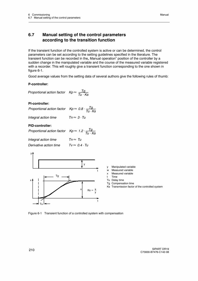
6 Commissioning6.7 Manual setting of the control parameters
Manual
210 SIPART DR19C73000-B7476-C142-08
6.7 Manual setting of the control parametersaccording to the transition function
If the transient function of the controlled system is active or can be determined, the controlparameters can be set according to the setting guidelines specified in the literature. Thetransient function can be recorded in the„ Manual operation” position of the controller by asudden change in the manipulated variable and the course of the measured variable registeredwith a recorder. This will roughly give a transient function corresponding to the one shown infigure 6-1.
Good average values from the setting data of several authors give the following rules of thumb:
P-controller:
Proportional action factor Kp≈ TgTu · Ks
PI-controller:
Proportional action factor Kp≈ 0.8 · TgTu · Ks
Integral action time Tn≈ 3 · Tu
PID-controller:
Proportional action factor Kp≈ 1.2 · TgTu · Ks
Integral action time Tn≈ Tu
Derivative action time Tv≈ 0.4 · Tu
y Manipulated variablew Measured variablex Measured variablet TimeTu Delay timeTg Compensation timeKs Transmission factor of the controlled system
y
t
x
t
Tg
x Ks = xy
Tu
y
Figure 6-1 Transient function of a controlled system with compensation
7 Application examples for configuring the controller7.1 General
Manual
SIPART DR19C73000-B7476-C142-08
211
7 Application examples for configuring the controller
7.1 General
Below frequent applications/connections of the SIPART DR19 devices are listed in the form ofconfiguration examples. The circuits are sorted according to their application S-controller,K-controller or two-position controller. All input and output connections and the order numbersof the respective required controllers or accessory modules are stated. A principle circuitdiagram of the control circuit and a short description make comprehension easier
We have purposely described the simple applications in very great detail to help the technicianabove all who only needs to design these circuits very occasionally.
Mains voltage
As shown, the power supply must be fused and the PE conductor connected. The permissiblepower supply range must be stated respectively with the type number of the controller.Fuses and connecting leads are not supplied with the controllers.
Input connections
A wide variety of input circuits are shown. Please note that the measuring range plug is requiredwhen using the analog input AI1 and the input variable mA/V. Feeding can take place from theSIPART DR19 controller when using two-wire transmitters.
Output circuits
The output circuits are represented uniformly: for the K-output for load independent currentsignal 0 or 4 to 20 mA, for S-output the switching outputs are output via the relays which maybe loaded with a maximum AC 250 V. If the setting outputs of the S-controller are desired withdigital signals, the digital outputs DO1 and DO2 must be used.
NOTICE
If inductances (e.g. stepper motors, contactors, etc.) are switched with theavailable relay outputs, adequate protection against interferenceby wiringwithRC-combinations or other suitablemeansmust beprovided on the systemsidein order to achieve EMC protection aims and because of wear on the contacts.
7 Application examples for configuring the controller7.1 General
Manual
212 SIPART DR19C73000-B7476-C142-08
D Configuration
Structure switches SAll controllers are supplied with the specified factory settings and must be structured to suitthe application during commissioning.
The necessary switch positions for the respective application in the examples butessential structure switches are named.
In addition other settings may be necessary due to system-specific criteria.
The following configuration examples have exclusively parallel circuits. Therefore thestructure switches which relate to the serial interface are not specified.
Parameters onPA and oFPAThe controllers must be adapted in every case using the system data. The factory setting ofthe control parameters must be selected so that the control loop does not tend to oscillateeven under worst case conditions (Kp = 0, 1, Tn = 9984 s). Kp and Tn or y0 and if necess-ary Tv and AH must be set.
UNI-input CAE1For the measuring variables TC/RTD/R sensor direct connection at AI1 the measuring rangeand the reference point temperature or line resistance must be set in all cases by the CAEmenu.For measuring variables mA/V the use of the measuring range plug 6DR2805-8J isrecommended.
Control algorithmAll configuration examples (except Z1) are shown for PI or PID behavior. Switching to P orPD behavior is possible with a digital input signal (structure switch S27). In the SIPARTDR19 as an S-controller a P- or PD-controller operation is only possible with externalposition feedback (S2=3).
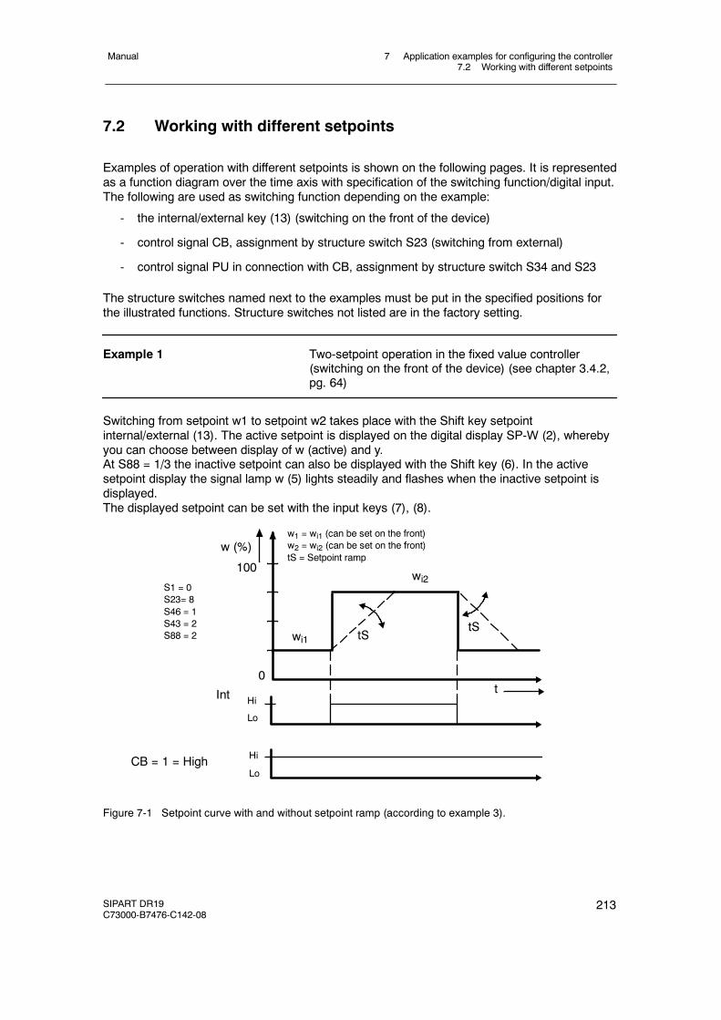
7 Application examples for configuring the controller7.2 Working with different setpoints
Manual
SIPART DR19C73000-B7476-C142-08
213
7.2 Working with different setpoints
Examples of operation with different setpoints is shown on the following pages. It is representedas a function diagram over the time axis with specification of the switching function/digital input.The following are used as switching function depending on the example:
- the internal/external key (13) (switching on the front of the device)
- control signal CB, assignment by structure switch S23 (switching from external)
- control signal PU in connection with CB, assignment by structure switch S34 and S23
The structure switches named next to the examples must be put in the specified positions forthe illustrated functions. Structure switches not listed are in the factory setting.
Example 1 Two-setpoint operation in the fixed value controller(switching on the front of the device) (see chapter 3.4.2,pg. 64)
Switching from setpoint w1 to setpoint w2 takes place with the Shift key setpointinternal/external (13). The active setpoint is displayed on the digital display SP-W (2), wherebyyou can choose between display of w (active) and y.At S88 = 1/3 the inactive setpoint can also be displayed with the Shift key (6). In the activesetpoint display the signal lamp w (5) lights steadily and flashes when the inactive setpoint isdisplayed.The displayed setpoint can be set with the input keys (7), (8).
wi2
wi1
t0
w (%)
100
S1 = 0S23= 8S46 = 1S43 = 2S88 = 2
w1 = wi1 (can be set on the front)w2 = wi2 (can be set on the front)tS = Setpoint ramp
Int
CB = 1 = HighLo
Hi
tStS
Lo
Hi
Figure 7-1 Setpoint curve with and without setpoint ramp (according to example 3).
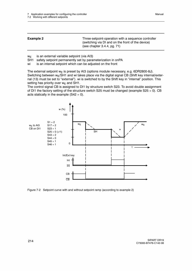
7 Application examples for configuring the controller7.2 Working with different setpoints
Manual
214 SIPART DR19C73000-B7476-C142-08
Example 2 Three-setpoint-operation with a sequence controller(switching via DI and on the front of the device)(see chapter 3.4.4, pg. 71)
wE is an external variable setpoint (via AI3)SH1 safety setpoint permanently set by parameterization in onPAwi is an internal setpoint which can be adjusted on the front
The external setpoint wE is preset by AI3 (options module necessary, e.g. 6DR2800-8J).Switching between wE/SH1 and wi takes place via the digital signal CB (Shift key internal/exter-nal (13) must be set to “external”). wi is switched to by the Shift key in “internal” position. Thissetting has priority over wE and SH1.The control signal CB is assigned to DI1 by structure switch S23. To avoid double assignmentof DI1 the factory setting of the structure switch S25 must be changed (example S25 = 0). CBacts statically in the example (S42 = 0).
SHw
t0
w (%)
100
Int
S1 = 2wE to AI3 S17 = 2CB on DI1 S23 = 1
S25 = 0 (¸1)S43 = 2S44 = 0S45 = 1S46 = 1
Int/Ext key
Int
CB
CB
wE wE
Figure 7-2 Setpoint curve with and without setpoint ramp (according to example 2)
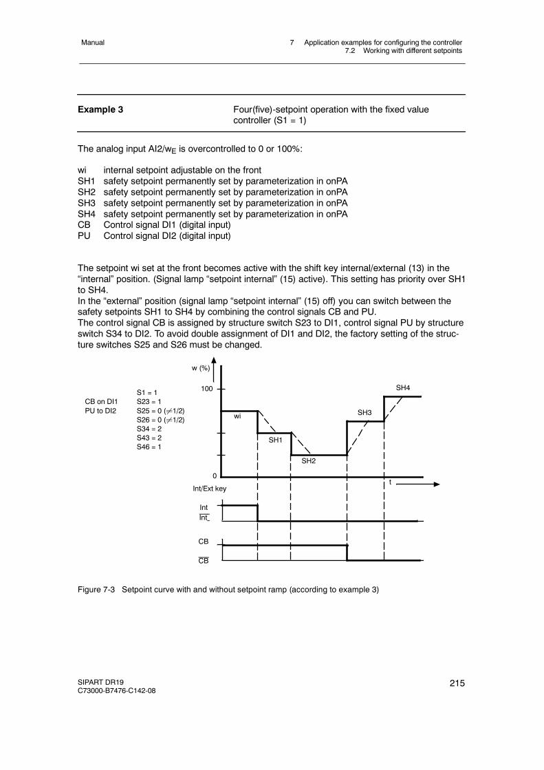
7 Application examples for configuring the controller7.2 Working with different setpoints
Manual
SIPART DR19C73000-B7476-C142-08
215
Example 3 Four(five)-setpoint operation with the fixed valuecontroller (S1 = 1)
The analog input AI2/wE is overcontrolled to 0 or 100%:
wi internal setpoint adjustable on the frontSH1 safety setpoint permanently set by parameterization in onPASH2 safety setpoint permanently set by parameterization in onPASH3 safety setpoint permanently set by parameterization in onPASH4 safety setpoint permanently set by parameterization in onPACB Control signal DI1 (digital input)PU Control signal DI2 (digital input)
The setpoint wi set at the front becomes active with the shift key internal/external (13) in the“internal” position. (Signal lamp “setpoint internal” (15) active). This setting has priority over SH1to SH4.In the “external” position (signal lamp “setpoint internal” (15) off) you can switch between thesafety setpoints SH1 to SH4 by combining the control signals CB and PU.The control signal CB is assigned by structure switch S23 to DI1, control signal PU by structureswitch S34 to DI2. To avoid double assignment of DI1 and DI2, the factory setting of the struc-ture switches S25 and S26 must be changed.
S1 = 1CB on DI1 S23 = 1PU to DI2 S25 = 0 (¸1/2)
S26 = 0 (¸1/2)S34 = 2S43 = 2S46 = 1
SH1
t0
100
IntInt
CB
CB
wi
Int/Ext key
SH2
SH3
SH4
w (%)
Figure 7-3 Setpoint curve with and without setpoint ramp (according to example 3)
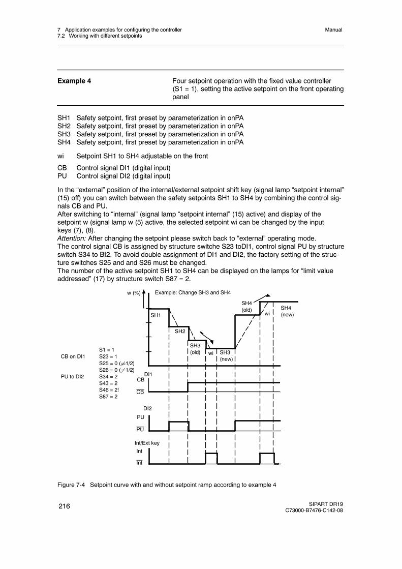
7 Application examples for configuring the controller7.2 Working with different setpoints
Manual
216 SIPART DR19C73000-B7476-C142-08
Example 4 Four setpoint operation with the fixed value controller(S1 = 1), setting the active setpoint on the front operatingpanel
SH1 Safety setpoint, first preset by parameterization in onPASH2 Safety setpoint, first preset by parameterization in onPASH3 Safety setpoint, first preset by parameterization in onPASH4 Safety setpoint, first preset by parameterization in onPA
wi Setpoint SH1 to SH4 adjustable on the front
CB Control signal DI1 (digital input)PU Control signal DI2 (digital input)
In the “external” position of the internal/external setpoint shift key (signal lamp “setpoint internal”(15) off) you can switch between the safety setpoints SH1 to SH4 by combining the control sig-nals CB and PU.After switching to “internal” (signal lamp “setpoint internal” (15) active) and display of thesetpoint w (signal lamp w (5) active, the selected setpoint wi can be changed by the inputkeys (7), (8).Attention: After changing the setpoint please switch back to “external” operating mode.The control signal CB is assigned by structure switche S23 toDI1, control signal PU by structureswitch S34 to BI2. To avoid double assignment of DI1 and DI2, the factory setting of the struc-ture switches S25 and and S26 must be changed.The number of the active setpoint SH1 to SH4 can be displayed on the lamps for “limit valueaddressed” (17) by structure switch S87 = 2.
w (%)
SH1
SH2
SH3(old) SH3
(new)
SH4(old) SH4
(new)wi
wiS1 = 1
CB on DI1 S23 = 1S25 = 0 (¸1/2)S26 = 0 (¸1/2)
PU to DI2 S34 = 2S43 = 2S46 = 2!S87 = 2
Int
Int
Int/Ext key
PU
DI2
PU
CBDI1
CB
Example: Change SH3 and SH4
Figure 7-4 Setpoint curve with and without setpoint ramp according to example 4
7 Application examples for configuring the controller7.3 Program controller, program transmitter
Manual
SIPART DR19C73000-B7476-C142-08
217
7.3 Program controller, program transmitter
Examples of program configuration for program controller/program transmitter is shown on thefollowing pages. It is represented as a function diagram over the time axis with specification ofthe switching function/digital input.The following are used as switching function depending on the example:
- the internal/external key (13) (switching on the front of the device)
- Control signal CB, assignment by structure switch S23 (Start/Stop program)
- Control signal PU, assignment by structure switch S34 (switching program P1/P2)(switching from external)
The structure switches named next to the examples must be put in the specified positions forthe illustrated functions. Structure switches not listed are in the factory setting.
When using as a program transmitter (prerequisite: K-standard controller) the setpoint w isassigned to the analog output by structure switch S57.
7 Application examples for configuring the controller7.3 Program controller, program transmitter
Manual
218 SIPART DR19C73000-B7476-C142-08
Example 1 Time program with program start on the front of thedevice, interval message by time slot, message end ofprogram, setpoint at start and end of programpermanently set.
DO1 Message output for Clb1, time section t.01.1 or t.05.1 activeDO2 Message output for Clb2, program not started or program endedwi internal setpoint adjustable on the front
The program is started by switching to external setpoint (Shift key setpoint internal/external(13)), message lamp “setpoint internal” (15) off). “setpoint” internal is switched back to automati-cally at the end of the program. The setpoint wi set on the front is active at the start and end ofthe program (S46 = 1). Assignment time slot CLb1 and CLb2 to DO1 and DO2 via S70 andS71. To avoid double assignment of DI1 and DI2, the factory setting of the structure switchesS63 and S64 must be changed.
The display “PV-X” (1) shows the remaining time in the active interval. In the “SP-W” (2) displayyou can choose between the current setpoint or target setpoint at the end of the interval (S88)with the Shift key (6). The program status is displayed in the analog display (3) (scope of pro-gram, program step).
The program is reset by the combination switching “setpoint internal” (13) and “manual” (9)operating mode.
Six program steps are specified in the example.
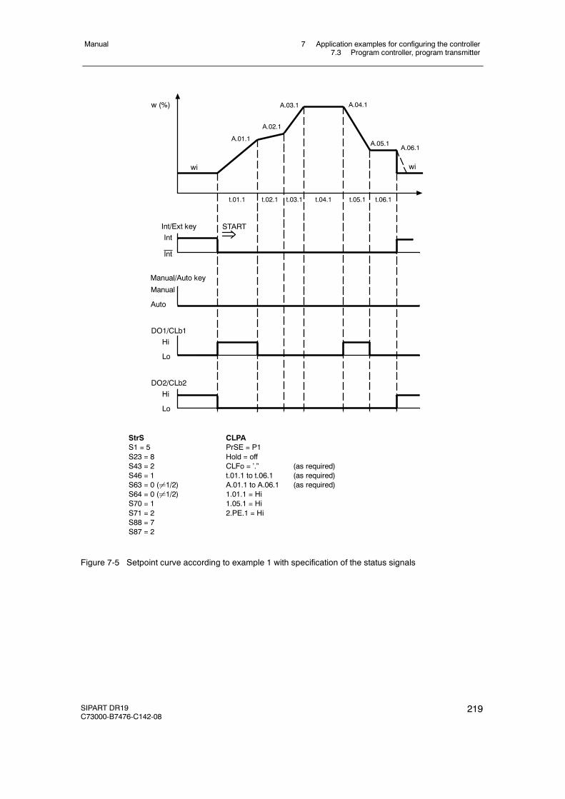
7 Application examples for configuring the controller7.3 Program controller, program transmitter
Manual
SIPART DR19C73000-B7476-C142-08
219
StrSS1 = 5S23 = 8S43 = 2S46 = 1S63 = 0 (¸1/2)S64 = 0 (¸1/2)S70 = 1S71 = 2S88 = 7S87 = 2
CLPAPrSE = P1Hold = offCLFo = ’.” (as required)t.01.1 to t.06.1 (as required)A.01.1 to A.06.1 (as required)1.01.1 = Hi1.05.1 = Hi2.PE.1 = Hi
Int
Int
Int/Ext key
Manual
Manual/Auto key
Auto
HiDO2/CLb2
Lo
HiDO1/CLb1
Lo
START
t.01.1 t.02.1 t.03.1 t.04.1 t.05.1 t.06.1
wi
w (%)
A.01.1
A.02.1
A.03.1 A.04.1
A.05.1A.06.1
wi
Figure 7-5 Setpoint curve according to example 1 with specification of the status signals
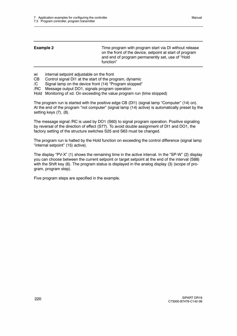
7 Application examples for configuring the controller7.3 Program controller, program transmitter
Manual
220 SIPART DR19C73000-B7476-C142-08
Example 2 Time program with program start via DI without releaseon the front of the device, setpoint at start of programand end of program permanently set, use of “Holdfunction”
wi internal setpoint adjustable on the frontCB Control signal DI1 at the start of the program, dynamic/C Signal lamp on the device front (14) “Program stopped”/RC Message output DO1, signals program operationHold Monitoring of xd. On exceeding the value program run (time stopped)
The program run is started with the positive edge CB (DI1) (signal lamp “Computer” (14) on).At the end of the program “not computer” (signal lamp (14) active) is automatically preset by thesetting keys (7), (8).
The message signal /RC is used by DO1 (S60) to signal program operation. Positive signalingby reversal of the direction of effect (S77). To avoid double assignment of DI1 and DO1, thefactory setting of the structure switches S25 and S63 must be changed.
The program run is halted by the Hold function on exceeding the control difference (signal lamp“internal setpoint” (15) active).
The display “PV-X” (1) shows the remaining time in the active interval. In the “SP-W” (2) displayyou can choose between the current setpoint or target setpoint at the end of the interval (S88)with the Shift key (6). The program status is displayed in the analog display (3) (scope of pro-gram, program step).
Five program steps are specified in the example.
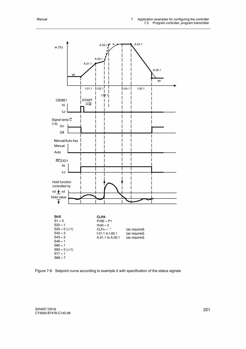
7 Application examples for configuring the controller7.3 Program controller, program transmitter
Manual
SIPART DR19C73000-B7476-C142-08
221
StrSS1 = 5S23 = 1S25 = 0 (¸1)S42 = 2S43 = 2S46 = 1S60 = 1S63 = 0 (¸1)S77 = 1S88 = 7
CLPAPrSE = P1Hold = 3CLFo = ’.” (as required)t.01.1 to t.05.1 (as required)A.01.1 to A.05.1 (as required)
START
t.01.1 t.02.1
t.03.1
t.04.1 t.05.1
wi
w (%)
A.01.1
A.02.1
A.03.1 A.04.1
A.05.1
wi
Manual
Manual/Auto key
Auto
HiCB/BE1
Lo
On
Signal lamp C(14)
Off
HiRC/DO1
Lo
Hold functioncontrolled by
xd xd
Hold value
Figure 7-6 Setpoint curve according to example 2 with specification of the status signals
7 Application examples for configuring the controller7.3 Program controller, program transmitter
Manual
222 SIPART DR19C73000-B7476-C142-08
Example 3 Time program with program start via DI after release onthe device front, setpoint at program start adjustable onthe front or last program setpoint, tracking of the programsetpoint to the internal setpoint
wi internal setpoint adjustable on the front at the program startwi (new) wi is tracked at the end of the program to the last program setpointw2 Setpoint change in the “internal” mode of the controllerCB Control signal DI1 at the program start, static
At external setpoint (13) (signal lamp “setpoint internal” (15) off) the program function is startedwith CB= high (DI1) (signal lamp “computer” (14) off). “setpoint internal” is switched to automati-cally at the end of the program (signal lamp “setpoint” internal (15) on). At the start of the pro-gram the setpoint wi set at the front is active. This is tracked to the last program setpoint A.03.1at the end of the program (S46 = 0).
The program run can be interrupted by switching to setpoint internal (13) and the current set-point changed by the input keys (7), (8). The switching is bumpless, starting from the set set-point the target setpoint at the end of the current program section is driven to over the remain-ing time (S46 = 0).
To avoid double assignment of DI1 the factory setting of the structure switch S25 must bechanged (example S25).
The display “PV-X” (1) shows the remaining time in the active interval. In the “SP-W” (2) displayyou can choose between the current setpoint or target setpoint at the end of the interval (S88)with the Shift key (6). The program status is displayed in the analog display (3) (scope of pro-gram, program step).
Three program steps are specified in the example.
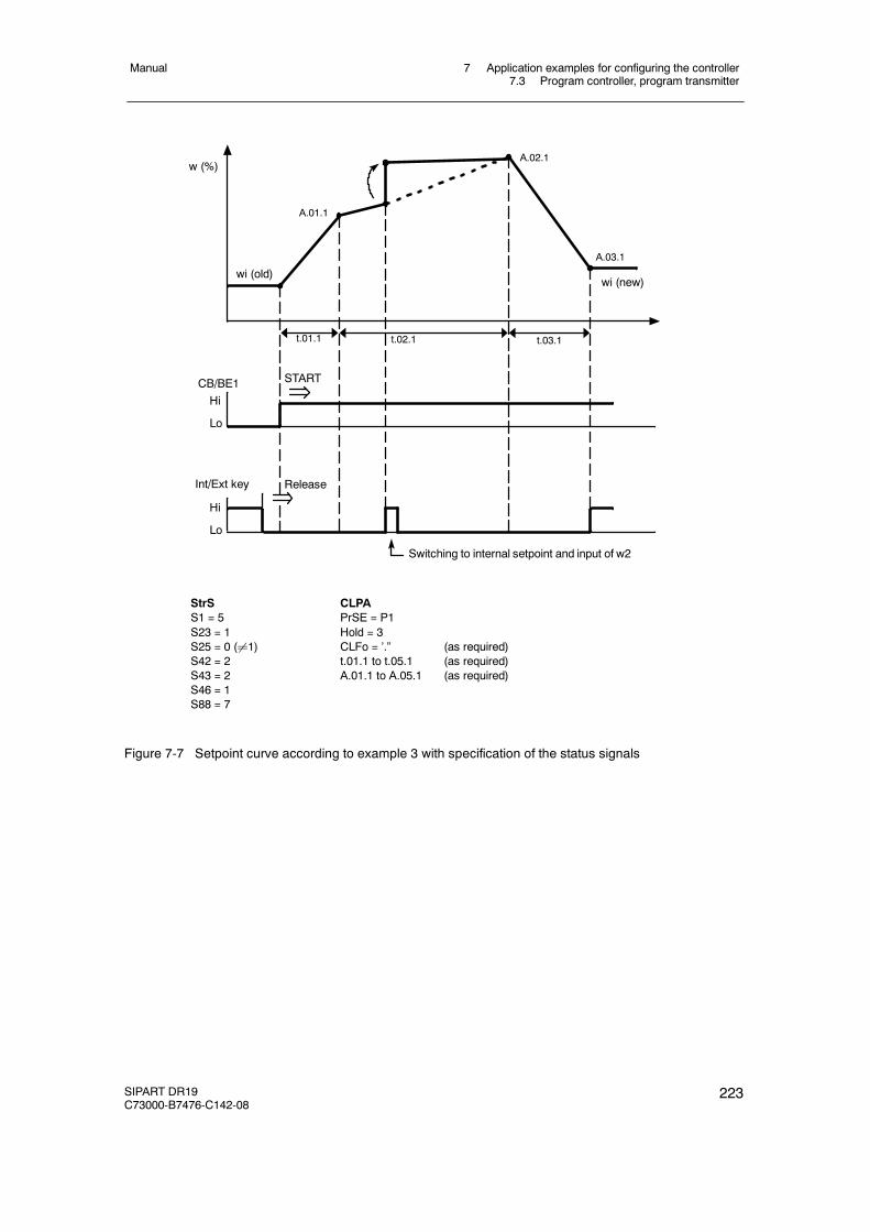
7 Application examples for configuring the controller7.3 Program controller, program transmitter
Manual
SIPART DR19C73000-B7476-C142-08
223
StrSS1 = 5S23 = 1S25 = 0 (¸1)S42 = 2S43 = 2S46 = 1S88 = 7
CLPAPrSE = P1Hold = 3CLFo = ’.” (as required)t.01.1 to t.05.1 (as required)A.01.1 to A.05.1 (as required)
START
t.01.1 t.02.1 t.03.1
wi (old)
w (%)
A.01.1
A.02.1
A.03.1
wi (new)
HiCB/BE1
Lo
Hi
Int/Ext key
Lo
Release
Switching to internal setpoint and input of w2
Figure 7-7 Setpoint curve according to example 3 with specification of the status signals
7 Application examples for configuring the controller7.3 Program controller, program transmitter
Manual
224 SIPART DR19C73000-B7476-C142-08
Example 4 Time program with cyclic program run, program start ondevice front, scope of program: 15 steps (P1 and P2connected), see chapter 3.4.3, pg. 67
wi internal setpoint adjustable on the front at the program startP1 Program section P1, display on signal lamp 1 (17)P2 Program section P2, display on signal lamp 2 (17)
The program is started by switching to external setpoint (Shift key setpoint internal/external(13)), message lamp “setpoint internal” (15) off). The programs P1 and P2 are connected witheach other (CLPA, PrSE = CASC).
The program run is repeated cyclically. Cancel by switching setpoint internal (13). At the start ofthe program the setpoint wi set at the front is active. This is tracked to the last program setpointA.05.2 at the end of the program (S46 = 0).
The display “PV-X” (1) shows the remaining time in the active interval. In the “SP-W” (2) displayyou can choose between setpoint or target setpoint at the end of the interval (S88) with theShift key (6). The program status is shown in the analog display (3) (current program step inP1, scope of program and current program step in P2).
The active program part P1/P2 is displayed on the signal lamps 1/2 (17).
Fifteen program steps are specified in the example.
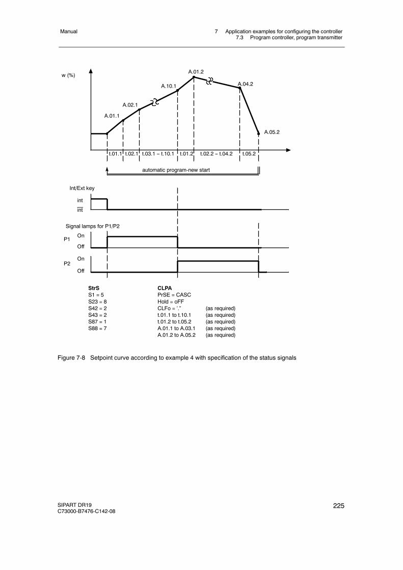
7 Application examples for configuring the controller7.3 Program controller, program transmitter
Manual
SIPART DR19C73000-B7476-C142-08
225
StrSS1 = 5S23 = 8S42 = 2S43 = 2S87 = 1S88 = 7
CLPAPrSE = CASCHold = oFFCLFo = ’.” (as required)t.01.1 to t.10.1 (as required)t.01.2 to t.05.2 (as required)A.01.1 to A.03.1 (as required)A.01.2 to A.05.2 (as required)
w (%)
Int/Ext key
int
int
A.01.1
Signal lamps for P1/P2
Off
On
t.01.1 t.02.1 t.01.2t.03.1 -- t.10.1 t.02.2 -- t.04.2 t.05.2
A.02.1
A.10.1
A.01.2
A.04.2
A.05.2
automatic program-new start
P1
Off
OnP2
Figure 7-8 Setpoint curve according to example 4 with specification of the status signals
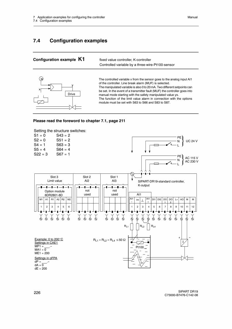
7 Application examples for configuring the controller7.4 Configuration examples
Manual
226 SIPART DR19C73000-B7476-C142-08
7.4 Configuration examples
Configuration example K1 fixed value controller, K-controllerControlled variable by a three-wire-Pt100-sensor
x
w
y
Drive
The controlled variable x from the sensor goes to the analog input AI1of the controller. Line break alarm (MUF) is selected.Themanipulated variable is also 0 to 20mA. Twodifferent setpoints canbe set. In the event of a transmitter fault (MUF) the controller goes intomanual mode starting with the safety manipulated value ys.The function of the limit value alarm in connection with the optionsmodule must be set with S63 to S66 and S83 to S87.
Please read the foreword to chapter 7.1, page 211
PENL
SIPART-DR19-standard controller,K-output
PENL
UC 24 V
AC 115 VAC 230 V
DI1 DI2 DO1
DO2
M ML+ AO
1 2 3 4 5 6 7 8 9 10 11 12
Setting the structure switches:S1 = 0S2 = 0S4 = 1S5 = 4S22 = 3
Slot 1AI3
notused
Slot 2AI2
notused
Slot 3Limit value
Option module6DR2801-8D
M1 A1 R2 M2R1 A2
1 2 3 4 5 6
--I
+
S43 = 2S51 = 2S63 = 3S64 = 4S67 = 1
Pt100
RL1 RL2 RL4
RL1 = RL2 = RL4≤50ΩExample: 0 to 200_CSettings in CAE1MP1 = ___.--MA1 = 0ME1 = 200
Settings in oFPAdP = ___.--dA = 0dE = 200
Im AI1+
AI1--
AI1
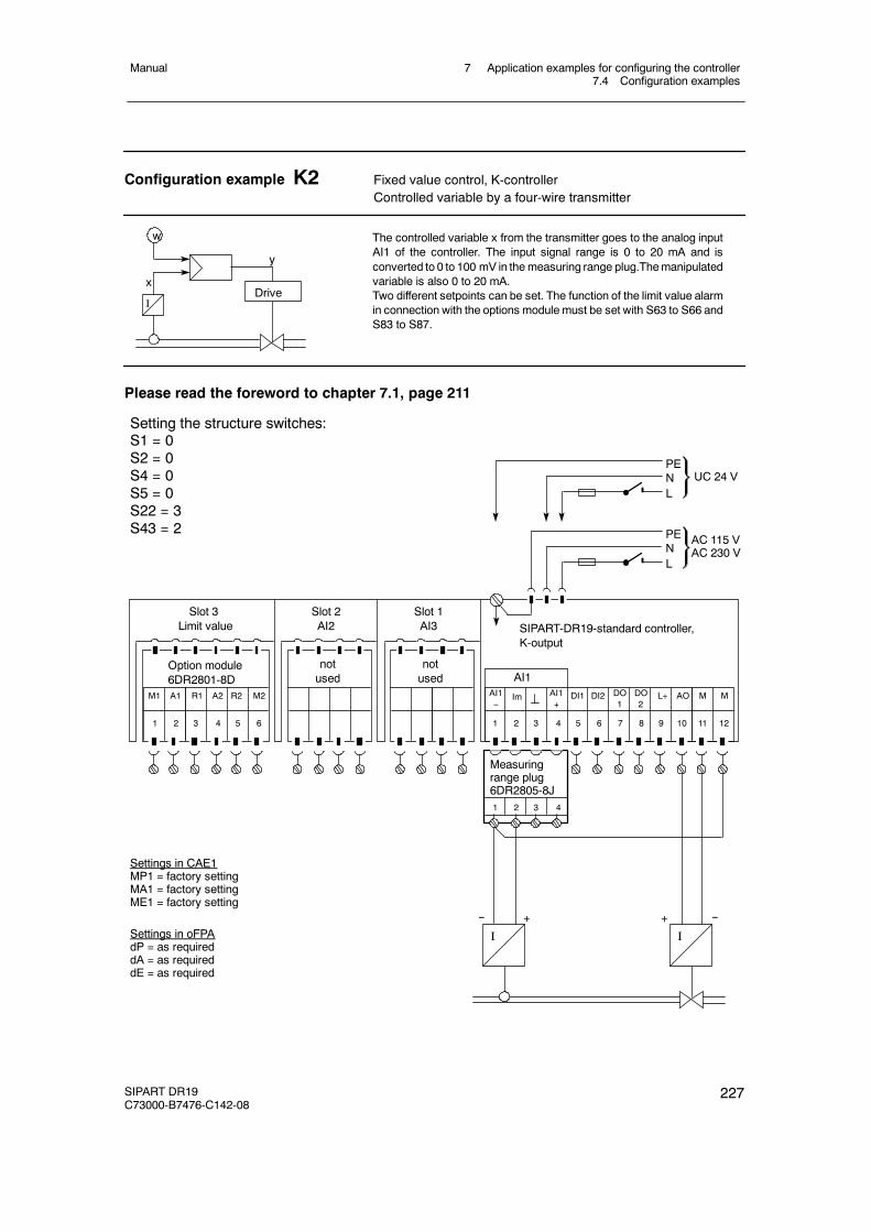
7 Application examples for configuring the controller7.4 Configuration examples
Manual
SIPART DR19C73000-B7476-C142-08
227
Configuration example K2 Fixed value control, K-controllerControlled variable by a four-wire transmitter
x
w
I
y
Drive
The controlled variable x from the transmitter goes to the analog inputAI1 of the controller. The input signal range is 0 to 20 mA and isconverted to 0 to 100 mV in themeasuring range plug.Themanipulatedvariable is also 0 to 20 mA.Two different setpoints can be set. The function of the limit value alarmin connection with the options module must be set with S63 to S66 andS83 to S87.
Please read the foreword to chapter 7.1, page 211
AI1--
PENL
SIPART-DR19-standard controller,K-output
PENL
UC 24 V
AC 115 VAC 230 V
Im AI1+
DI1 DI2 DO1
DO2
M ML+ AO
1 2 3 4 5 6 7 8 9 10 11 12
Setting the structure switches:S1 = 0S2 = 0S4 = 0S5 = 0S22 = 3S43 = 2
Slot 1AI3
notused
Slot 2AI2
notused
Slot 3Limit value
Option module6DR2801-8D
M1 A1 R2 M2R1 A2
1 2 3 4 5 6
--
I
+
Settings in CAE1MP1 = factory settingMA1 = factory settingME1 = factory setting
Settings in oFPAdP = as requireddA = as requireddE = as required
Measuringrange plug6DR2805-8J
AI1
1 2 3 4
--
I
+
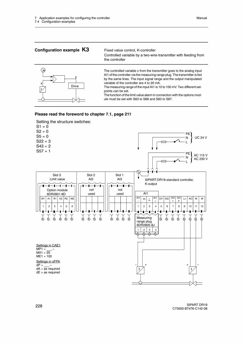
7 Application examples for configuring the controller7.4 Configuration examples
Manual
228 SIPART DR19C73000-B7476-C142-08
Configuration example K3 Fixed value control, K-controllerControlled variable by a two-wire-transmitter with feeding fromthe controller
x
w
I
y
Drive
The controlled variable x from the transmitter goes to the analog inputAI1 of the controller via themeasuring range plug. The transmitter is fedby the same lines. The input signal range and the output manipulatedvariable of the controller are 4 to 20 mA.Themeasuring range of the input AI1 is 10 to 100mV. Two different set-points can be set.The function of the limit value alarm in connection with the optionsmod-ule must be set with S63 to S66 and S83 to S87.
Please read the foreword to chapter 7.1, page 211
AI1--
PENL
SIPART-DR19-standard controller,K-output
PENL
UC 24 V
AC 115 VAC 230 V
Im AI1+
DI1 DI2 DO1
DO2
M ML+ AO
1 2 3 4 5 6 7 8 9 10 11 12
Setting the structure switches:S1 = 0S2 = 0S5 = 0S22 = 3S43 = 2S57 = 1
Slot 1AI3
notused
Slot 2AI2
notused
Slot 3Limit value
Option module6DR2801-8D
M1 A1 R2 M2R1 A2
1 2 3 4 5 6
--I
+ --I
+
Settings in CAE1MP1 = ___.--MA1 = 20ME1 = 100
Settings in oFPAdP = ___.--dA = as requireddE = as required
Measuringrange plug6DR2805-8J
AI1
1 2 3 4
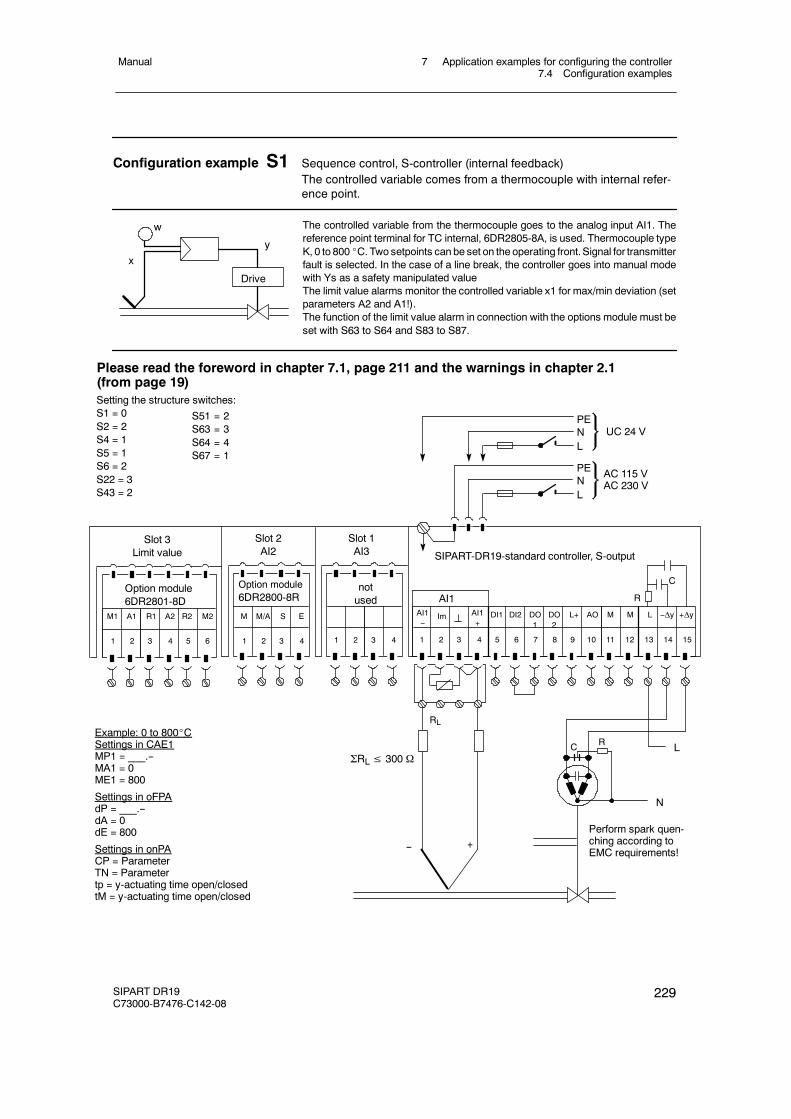
7 Application examples for configuring the controller7.4 Configuration examples
Manual
SIPART DR19C73000-B7476-C142-08
229
Configuration example S1 Sequence control, S-controller (internal feedback)The controlled variable comes from a thermocouple with internal refer-ence point.
The controlled variable from the thermocouple goes to the analog input AI1. Thereference point terminal for TC internal, 6DR2805-8A, is used. Thermocouple typeK, 0 to 800 _C. Two setpoints can be set on the operating front.Signal for transmitterfault is selected. In the case of a line break, the controller goes into manual modewith Ys as a safety manipulated valueThe limit value alarms monitor the controlled variable x1 for max/min deviation (setparameters A2 and A1!).The function of the limit value alarm in connection with the options module must beset with S63 to S64 and S83 to S87.
w
xy
Drive
Please read the foreword in chapter 7.1, page 211 and the warnings in chapter 2.1(from page 19)Setting the structure switches:S1 = 0S2 = 2S4 = 1S5 = 1S6 = 2S22 = 3S43 = 2
Example: 0 to 800_CSettings in CAE1MP1 = ___.--MA1 = 0ME1 = 800
Settings in oFPAdP = ___.--dA = 0dE = 800
Settings in onPACP = ParameterTN = Parametertp = y-actuating time open/closedtM = y-actuating time open/closed
PENL
PENL
UC 24 V
AC 115 VAC 230 V
DI1 DI2 DO1
DO2
M ML+ AO
1 2 3 4 5 6 7 8 9 10 11 12
Slot 1AI3
Slot 2AI2
Slot 3Limit value
Option module6DR2801-8D
M1 A1 R2 M2R1 A2
1 2 3 4 5 6
notused
M M/A S E
1 2 3 4
Option module6DR2800-8R
L +Δy
13 14 15
--Δy
SIPART-DR19-standard controller, S-output
LRC
N
Perform spark quen-ching according toEMC requirements!
R
C
1 2 3 4
AI1--
Im AI1+
AI1
RL
-- +
ΣRL≤ 300 Ω
S51 = 2S63 = 3S64 = 4S67 = 1
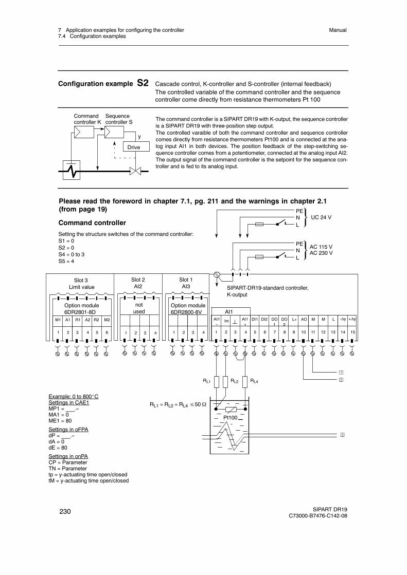
7 Application examples for configuring the controller7.4 Configuration examples
Manual
230 SIPART DR19C73000-B7476-C142-08
Configuration example S2 Cascade control, K-controller and S-controller (internal feedback)The controlled variable of the command controller and the sequencecontroller come directly from resistance thermometers Pt 100
The command controller is a SIPART DR19 with K-output, the sequence controlleris a SIPART DR19 with three-position step output.The controlled varaible of both the command controller and sequence controllercomes directly from resistance thermometers Pt100 and is connected at the ana-log input AI1 in both devices. The position feedback of the step-switching se-quence controller comes from a potentiometer, connected at the analog input AI2.The output signal of the command controller is the setpoint for the sequence con-troller and is fed to its analog input.
y
Drive
Commandcontroller K
Sequencecontroller S
Command controller
Setting the structure switches of the command controller:S1 = 0S2 = 0S4 = 0 to 3S5 = 4
Slot 1AI3
Slot 2AI2
notused
Slot 3Limit value
Option module6DR2801-8D
M1 A1 R2 M2R1 A2
1 2 3 4 5 6
Option module6DR2800-8V
1 2 3 4
Please read the foreword in chapter 7.1, pg. 211 and the warnings in chapter 2.1(from page 19)
PENL
SIPART-DR19-standard controller,K-output
PENL
UC 24 V
AC 115 VAC 230 V
DI1 DI2 DO1
DO2
M ML+ AO
1 2 3 4 5 6 7 8 9 10 11 12
-ΔyL
13 14 15
+Δy
Pt100
RL1 = RL2 = RL4≤50Ω
RL1 RL2 RL4
1 2 3 4
¡
©
¢
AI1--
Im AI1+
AI1
Example: 0 to 800_CSettings in CAE1MP1 = ___.--MA1 = 0ME1 = 80
Settings in oFPAdP = ___.--dA = 0dE = 80
Settings in onPACP = ParameterTN = Parametertp = y-actuating time open/closedtM = y-actuating time open/closed
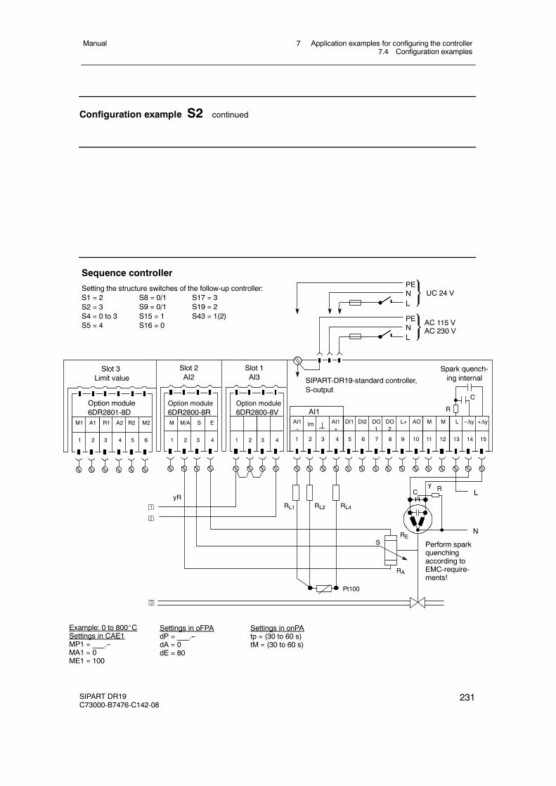
7 Application examples for configuring the controller7.4 Configuration examples
Manual
SIPART DR19C73000-B7476-C142-08
231
Configuration example S2 continued
PENL
PENL
UC 24 V
AC 115 VAC 230 V
DI1 DI2 DO1
DO2
M ML+ AO
1 2 3 4 5 6 7 8 9 10 11 12
Sequence controller
Setting the structure switches of the follow-up controller:S1 = 2S2 = 3S4 = 0 to 3S5 = 4
Slot 1AI3
Slot 2AI2
Spark quench-ing internal
Slot 3Limit value
Option module6DR2801-8D
M1 A1 R2 M2R1 A2
1 2 3 4 5 6
M M/A S E
1 2 3 4
Option module6DR2800-8R
L +Δy
13 14 15
--Δy
SIPART-DR19-standard controller,S-output
LRC
N
Perform sparkquenchingaccording toEMC-require-ments!
y
RA
RES
Option module6DR2800-8V
1 2 3 4
RL1 RL2 RL4yR
Pt100
R
C
¡
©
¢
S8 = 0/1S9 = 0/1S15 = 1S16 = 0
S17 = 3S19 = 2S43 = 1(2)
Example: 0 to 800_CSettings in CAE1MP1 = ___.--MA1 = 0ME1 = 100
Settings in oFPAdP = ___.--dA = 0dE = 80
Settings in onPAtp = (30 to 60 s)tM = (30 to 60 s)
AI1--
Im AI1+
AI1
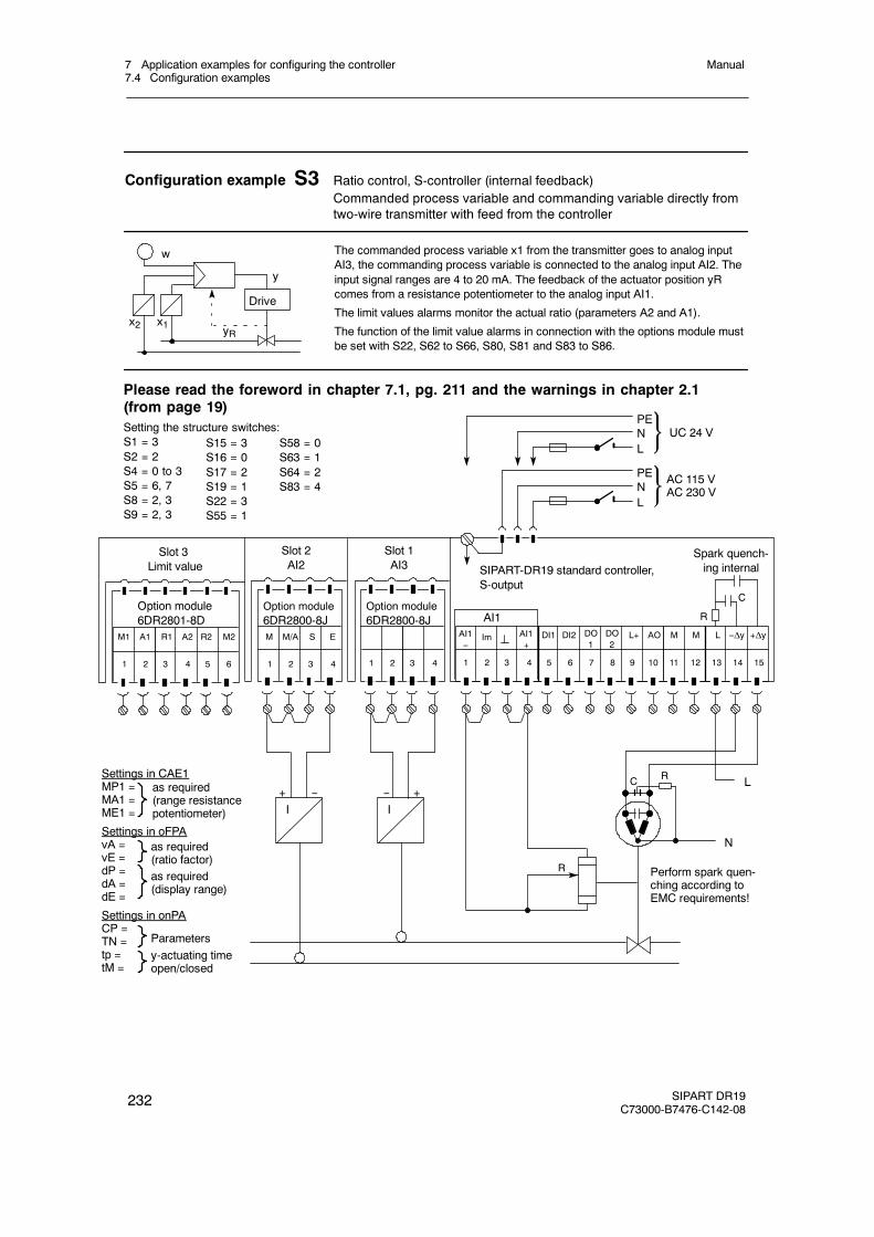
7 Application examples for configuring the controller7.4 Configuration examples
Manual
232 SIPART DR19C73000-B7476-C142-08
Configuration example S3 Ratio control, S-controller (internal feedback)Commanded process variable and commanding variable directly fromtwo-wire transmitter with feed from the controller
The commanded process variable x1 from the transmitter goes to analog inputAI3, the commanding process variable is connected to the analog input AI2. Theinput signal ranges are 4 to 20 mA. The feedback of the actuator position yRcomes from a resistance potentiometer to the analog input AI1.
The limit values alarms monitor the actual ratio (parameters A2 and A1).
The function of the limit value alarms in connection with the options module mustbe set with S22, S62 to S66, S80, S81 and S83 to S86.
x2
w
y
Drive
yRx1
PENL
PENL
UC 24 V
AC 115 VAC 230 V
DI1 DI2 DO1
DO2
M ML+ AO
1 2 3 4 5 6 7 8 9 10 11 12
Setting the structure switches:S1 = 3S2 = 2S4 = 0 to 3S5 = 6, 7S8 = 2, 3S9 = 2, 3
Slot 1AI3
Slot 2AI2
Spark quench-ing internal
Slot 3Limit value
Option module6DR2801-8D
M1 A1 R2 M2R1 A2
1 2 3 4 5 6
M M/A S E
1 2 3 4
Option module6DR2800-8J
L +Δy
13 14 15
--Δy
S15 = 3S16 = 0S17 = 2S19 = 1S22 = 3S55 = 1
Please read the foreword in chapter 7.1, pg. 211 and the warnings in chapter 2.1(from page 19)
SIPART-DR19 standard controller,S-output
LRC
N
Perform spark quen-ching according toEMC requirements!
R
C
I+ --
R
I+--
1 2 3 4
Option module6DR2800-8J
Settings in CAE1MP1 =MA1 =ME1 =
Settings in oFPAvA =vE =dP =dA =dE =
Settings in onPACP =TN =tp =tM =
as required(range resistancepotentiometer)
as required(ratio factor)as required(display range)
Parametersy-actuating timeopen/closed
AI1--
Im AI1+
AI1
S58 = 0S63 = 1S64 = 2S83 = 4
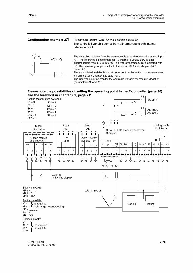
7 Application examples for configuring the controller7.4 Configuration examples
Manual
SIPART DR19C73000-B7476-C142-08
233
Configuration example Z1 Fixed value control with PD two-position controllerThe controlled variable comes from a thermocouple with internalreference point.
The controlled variable from the thermocouple goes directly to the analog inputAI1. The reference point element for TC internal, 6DR2805-8A, is used.Thermocouple type J, 0 to 400 _C. The type of thermocouple is selected withS6. The measuring range is set with the menu CAE1 (see chapter 5.4.7,page 191).The manipulated variable is output dependent on the setting of the parametersY1 and Y2 (see Chapter 3.6, page 101).The limit value alarms monitor the controlled variable for max/min deviation(parameters A2 and A1).
w+Δy / --Δy
x
PENL
PENL
UC 24 V
AC 115 VAC 230 V
DI1 DI2 DO1
DO2
M ML+ AO
1 2 3 4 5 6 7 8 9 10 11 12
Setting the structure switches:S1 = 0S2 = 1S5 = 1S6 = 1S15 = 1S22 = 3
Slot 1AI3
Slot 2AI2
Slot 3Limit value
Option module6DR2801-8D
M1 A1 R2 M2R1 A2
1 2 3 4 5 6
notused
1 2 3 4
Option module6DR2801-8V
L +Δy
13 14 15
--Δy
S27 = 8S58 = 0S63 = 3S64 = 4S83 = 1
Please note the possibilities of setting the operating point in the P-controller (page 98)and the foreword in chapter 7.1, page 211
SIPART-DR19-standard controller,S-output
L
1 2 3 4
Cooling Heating
NΣRL≤ 300 Ω
-- +IAI1--
Im AI1+
AI1 R
C
Spark quench-ing internal
RL
-- +
externallimit value display
Settings in CAE1MP1 = ___.--MA1 = 0ME1 = 400
Settings in oFPAy1=y2=dP = _ _ _ _dA = 0dE = 400
Settings in onPACP =TN =tp =tM =
as required(split range heating/cooling)
as requiredy0 = 50 %
7 Application examples for configuring the controller7.5 Configuring tool, forms
Manual
234 SIPART DR19C73000-B7476-C142-08
7.5 Configuring tool, forms
We recommend the following procedure for solving your controller problems:
- Determining the assembly of the controller.- If necessary: Determine position of jumpers and switches of the backplane module and the
signal transformer.- Drawing the wiring diagram.- Settings to be entered further down in the onPA, oFPA and Stru and CAE1 list (structuring,
parameterization).- The SIMATIC PDM user interface is available for PC-supported configurations.
For notes
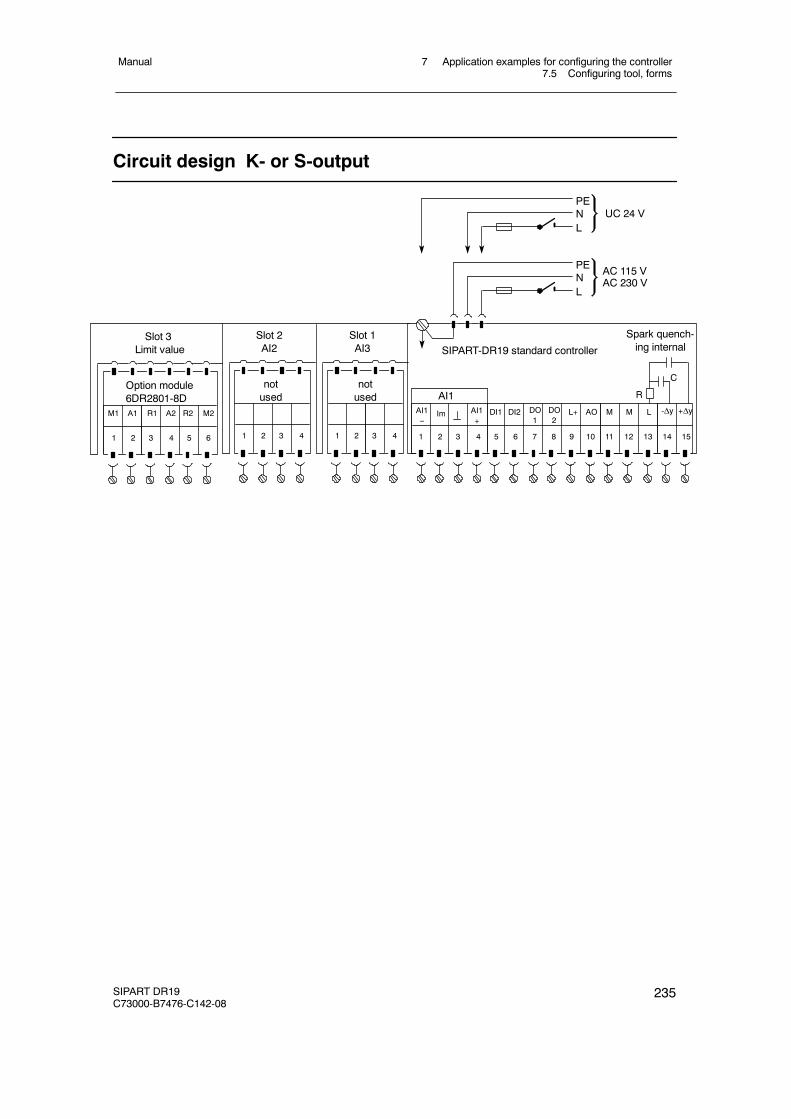
7 Application examples for configuring the controller7.5 Configuring tool, forms
Manual
SIPART DR19C73000-B7476-C142-08
235
Circuit design K- or S-output
Slot 1AI3
Slot 2AI2
notused
Slot 3Limit value
Option module6DR2801-8D
M1 A1 R2 M2R1 A2
1 2 3 4 5 6
notused
PENL
SIPART-DR19 standard controller
PENL
UC 24 V
AC 115 VAC 230 V
DI1 DI2 DO1
DO2
M ML+ AO
1 2 3 4 5 6 7 8 9 10 11 12
-ΔyL
13 14 15
+Δy
1 2 3 4 1 2 3 4
AI1--
Im AI1+
AI1 R
C
Spark quench-ing internal
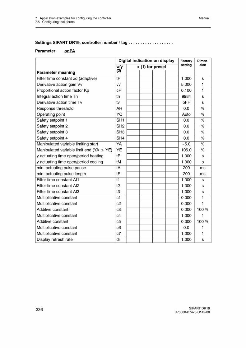
7 Application examples for configuring the controller7.5 Configuring tool, forms
Manual
236 SIPART DR19C73000-B7476-C142-08
Settings SIPART DR19, controller number / tag . . . . . . . . . . . . . . . . . . .
Parameter onPA
Digital indication on display Factorytti
Dimen-iw/y
(2)x (1) for preset
ysetting sion
Parameter meaningy
(2)
Filter time constant xd (adaptive) tF 1.000 s( p )Derivative action gain Vv vv 5.000 1gProportional action factor Kp cP 0.100 1p pIntegral action time Tn tn 9984 sgDerivative action time Tv tv oFF sResponse threshold AH 0.0 %pOperating point YO Auto %Safety setpoint 1 SH1 0.0 %y pSafety setpoint 2 SH2 0.0 %y pSafety setpoint 3 SH3 0.0 %y pSafety setpoint 4 SH4 0.0 %Manipulated variable limiting start YA --5.0 %p gManipulated variable limit end (YA≤ YE) YE 105.0 %p ( )y actuating time open/period heating tP 1.000 sy g p p gy actuating time open/period cooling tM 1.000 smin. actuating pulse pause tA 200 msg p pmin. actuating pulse length tE 200 msFilter time constant AI1 t1 1.000 sFilter time constant AI2 t2 1.000 sFilter time constant AI3 t3 1.000 sMultiplicative constant c1 0.000 1pMultiplicative constant c2 0.000 1pAdditive constant c3 0.000 100 %Multiplicative constant c4 1.000 1pAdditive constant c5 0.000 100 %Multiplicative constant c6 0.0 1pMultiplicative constant c7 1.000 1Display refresh rate dr 1.000 s
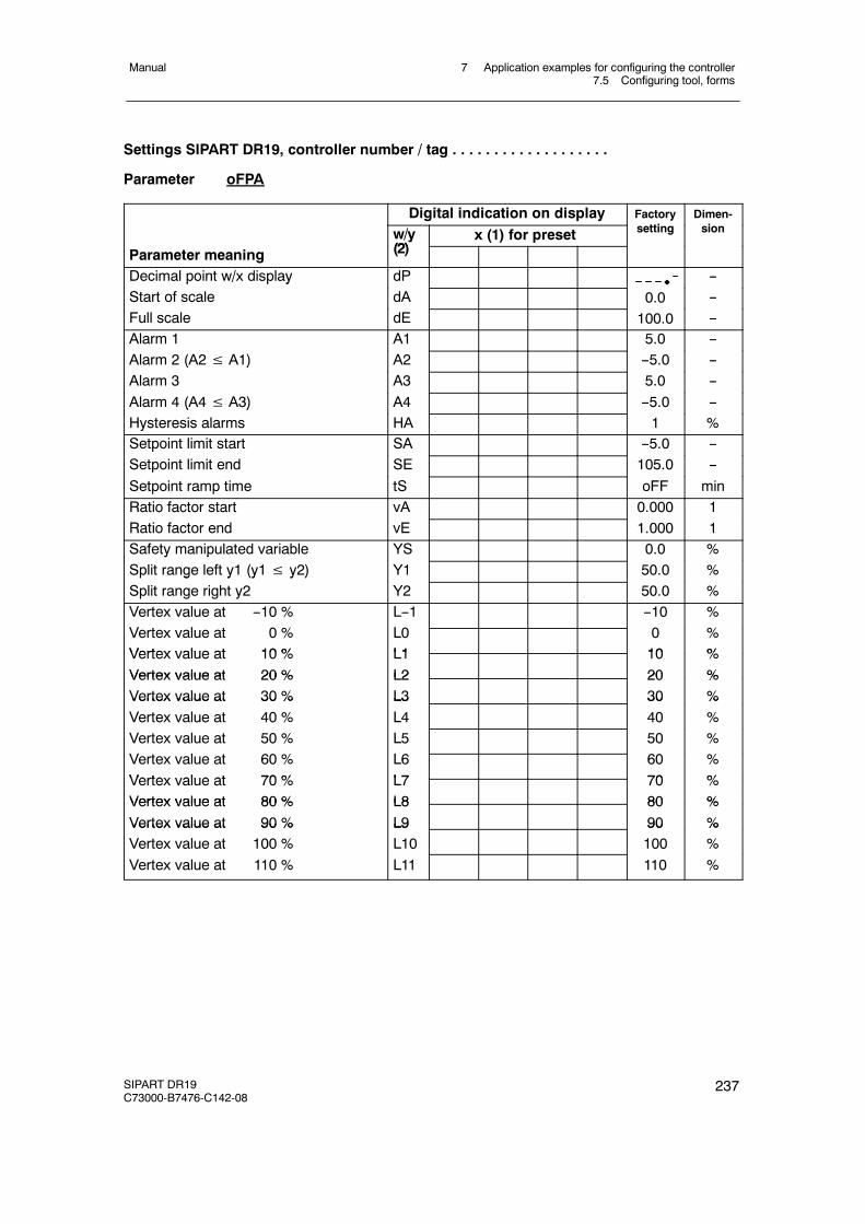
7 Application examples for configuring the controller7.5 Configuring tool, forms
Manual
SIPART DR19C73000-B7476-C142-08
237
Settings SIPART DR19, controller number / tag . . . . . . . . . . . . . . . . . . .
Parameter oFPA
Digital indication on display Factorytti
Dimen-iw/y
(2)x (1) for preset
ysetting sion
Parameter meaningy
(2)
Decimal point w/x display dP --p p yStart of scale dA 0.0 --Full scale dE 100.0 --Alarm 1 A1 5.0 --Alarm 2 (A2≤ A1) A2 --5.0 --( )Alarm 3 A3 5.0 --Alarm 4 (A4≤ A3) A4 --5.0 --( )Hysteresis alarms HA 1 %Setpoint limit start SA --5.0 --pSetpoint limit end SE 105.0 --Setpoint ramp time tS oFF minRatio factor start vA 0.000 1Ratio factor end vE 1.000 1Safety manipulated variable YS 0.0 %y pSplit range left y1 (y1≤ y2) Y1 50.0 %p g y (y y )Split range right y2 Y2 50.0 %Vertex value at --10 %V l 0 %
L--1L0
--100
%%Vertex value at 0 %
Vertex value at 10 %L0L1
010
%%Vertex value at 10 %
Vertex value at 20 %L1L2
1020
%%Vertex value at 20 %
Vertex value at 30 %L2L3
2030
%%Vertex value at 30 %
Vertex value at 40 %L3L4
3040
%%
Vertex value at 50 % L5 50 %Vertex value at 60 %Vertex value at 70 %
L6L7
6070
%%Vertex value at 70 %
Vertex value at 80 %L7L8
7080
%%Vertex value at 80 %
Vertex value at 90 %L8L9
8090
%%Vertex value at 90 %
Vertex value at 100 %L9L10
90100
%%
Vertex value at 110 % L11 110 %
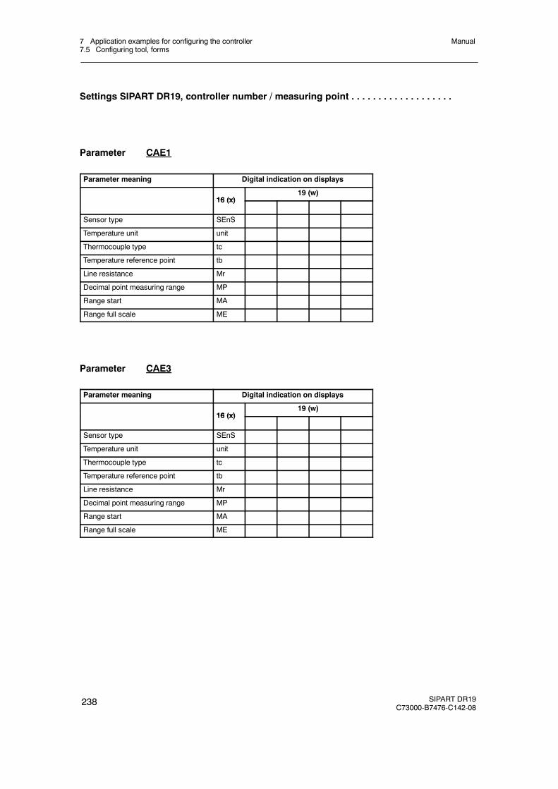
7 Application examples for configuring the controller7.5 Configuring tool, forms
Manual
238 SIPART DR19C73000-B7476-C142-08
Settings SIPART DR19, controller number / measuring point . . . . . . . . . . . . . . . . . . .
Parameter CAE1
Parameter meaning Digital indication on displays
16 (x)19 (w)
16 (x)
Sensor type SEnS
Temperature unit unit
Thermocouple type tc
Temperature reference point tb
Line resistance Mr
Decimal point measuring range MP
Range start MA
Range full scale ME
Parameter CAE3
Parameter meaning Digital indication on displays
16 (x)19 (w)
16 (x)
Sensor type SEnS
Temperature unit unit
Thermocouple type tc
Temperature reference point tb
Line resistance Mr
Decimal point measuring range MP
Range start MA
Range full scale ME
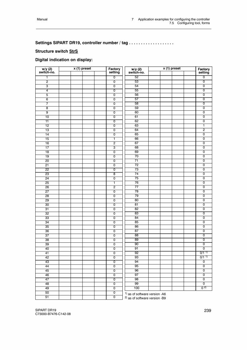
7 Application examples for configuring the controller7.5 Configuring tool, forms
Manual
SIPART DR19C73000-B7476-C142-08
239
Settings SIPART DR19, controller number / tag . . . . . . . . . . . . . . . . . . .
Structure switch StrS
Digital indication on display:
w/y (2)i h
x (1) preset Factoryi
w/y (2)switch-no.
Factorysetting
1 02 03 04 05 06 07 08 09 010 011 012 013 014 015 116 217 318 019 020 021 022 023 824 025 126 227 028 029 030 031 032 033 034 035 036 037 038 039 040 041 042 043 044 045 046 047 048 049 050 051 0
w/y (2) x (1) preset Factoryw/y (2)switch-no.
Factorysetting
52 053 054 055 056 057 058 059 060 061 062 063 164 265 066 067 068 069 070 071 072 073 074 075 076 077 078 079 080 081 082 083 084 085 086 087 088 089 090 091 092 0/1 1)
93 0/1 1)
94 095 096 097 098 099 0100 0 2)
1) as of software version -A62) as of software version -B9

7 Application examples for configuring the controller7.5 Configuring tool, forms
Manual
240 SIPART DR19C73000-B7476-C142-08
8 Maintenance8.1 General information and handling
Manual
SIPART DR19C73000-B7476-C142-08
241
8 Maintenance
8.1 General information and handling
The controller is maintenance-free. White spirit or industrial alcohol is recommended forcleaning the front foil and the plastic housing if necessary.
Be changed freely without readjustment with power supplied. The other modules may also bereplaced without readjustment (procedure as described in chapter 8.2).
CAUTION
Allmodules contain componentswhichare vulnerable to static. Observethe safety precautions!
S-final control elements on S-controllers remain in their last position.
! WARNING
The backplane module may only be exchanged when the power supplyhas been safely disconnected!
! WARNING
Modules may only be repaired in an authorized workshop. This appliesparticularly to the backplane module because of the safety functions(safe disconnection and safety extra low voltages).
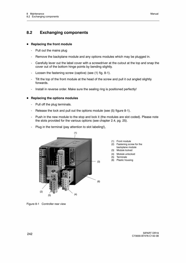
8 Maintenance8.2 Exchanging components
Manual
242 SIPART DR19C73000-B7476-C142-08
8.2 Exchanging components
D Replacing the front module
- Pull out the mains plug
- Remove the backplane module and any options modules which may be plugged in.
- Carefully lever out the label cover with a screwdriver at the cutout at the top and snap thecover out of the bottom hinge points by bending slightly.
- Loosen the fastening screw (captive) (see (1) fig. 8-1).
- Tilt the top of the front module at the head of the screw and pull it out angled slightlyforwards.
- Install in reverse order. Make sure the sealing ring is positioned perfectly!
D Replacing the options modules
- Pull off the plug terminals.
- Release the lock and pull out the options module (see (5) figure 8-1).
- Push in the new module to the stop and lock it (the modules are slot coded). Please notethe slots provided for the various options (see chapter 2.4, pg. 25).
- Plug in the terminal (pay attention to slot labeling!),
(1)
(6)
(3)
(1) Front module(2) Fastening screw for the
backplane module(3) Module locked
(4) Module unlocked(5) Terminals(6) Plastic housing
(5) (4)(2)
Figure 8-1 Controller rear view
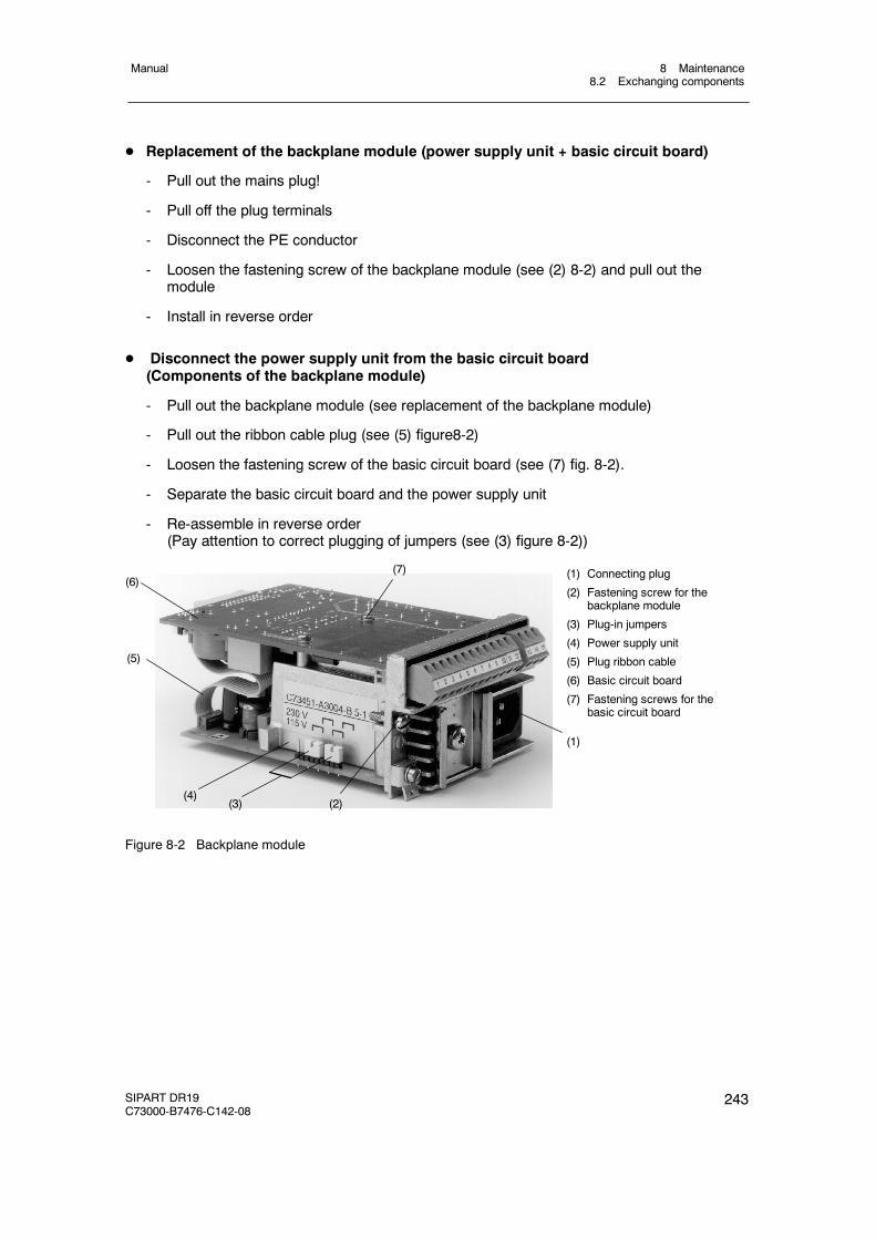
8 Maintenance8.2 Exchanging components
Manual
SIPART DR19C73000-B7476-C142-08
243
D Replacement of the backplane module (power supply unit + basic circuit board)
- Pull out the mains plug!
- Pull off the plug terminals
- Disconnect the PE conductor
- Loosen the fastening screw of the backplane module (see (2) 8-2) and pull out themodule
- Install in reverse order
D Disconnect the power supply unit from the basic circuit board(Components of the backplane module)
- Pull out the backplane module (see replacement of the backplane module)
- Pull out the ribbon cable plug (see (5) figure8-2)
- Loosen the fastening screw of the basic circuit board (see (7) fig. 8-2).
- Separate the basic circuit board and the power supply unit
- Re-assemble in reverse order(Pay attention to correct plugging of jumpers (see (3) figure 8-2))
(1) Connecting plug
(2) Fastening screw for thebackplane module
(3) Plug-in jumpers
(4) Power supply unit
(5) Plug ribbon cable
(6) Basic circuit board
(7) Fastening screws for thebasic circuit board
(7)(6)
(5)
(4)(3) (2)
(1)
Figure 8-2 Backplane module
8 Maintenance8.3 LED-test and software state
Manual
244 SIPART DR19C73000-B7476-C142-08
8.3 LED-test and software state
If the Shift key (6) is pressed for about 10 s (“ PS” flashes on the manipulated variable displayafter about 5 s), this leads to the LED-test. All LEDs light up, the displays show “8.8.8.8.” and a2 LED wide light mark runs on the bargraph from 0 to 100 % (on reaching 100 % the light marksstarts again at 0 %).
If the internal/external key (13) is kept pressed permanently during the lamp guiding, “dr19”appears on the digital x/w display and the device software version appears on the digital w/ydisplay.
During the LED-test and display of the software state the controller continues to operate onlinein its last operating mode.
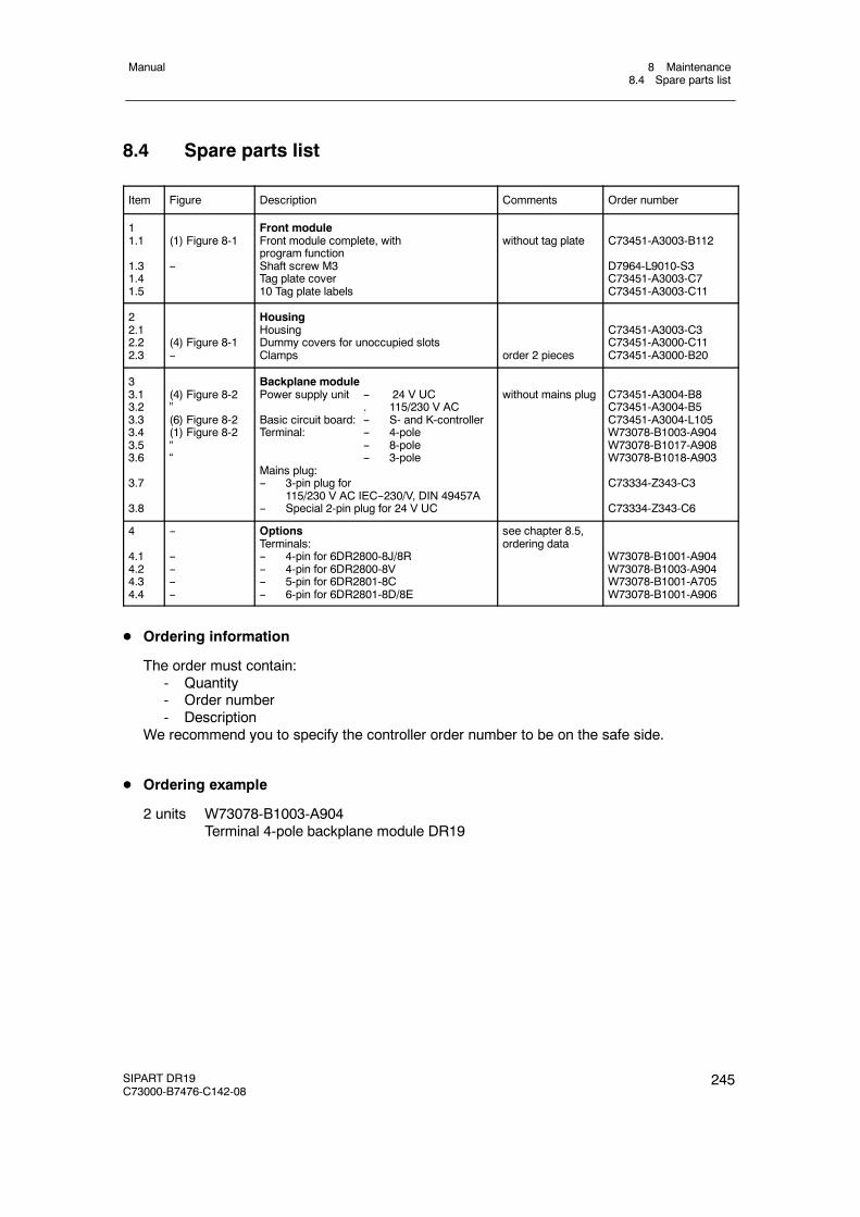
8 Maintenance8.4 Spare parts list
Manual
SIPART DR19C73000-B7476-C142-08
245
8.4 Spare parts list
Item Figure Description Comments Order number
11.1
1.31.41.5
(1) Figure 8-1
--
Front moduleFront module complete, withprogram functionShaft screw M3Tag plate cover10 Tag plate labels
without tag plate C73451-A3003-B112
D7964-L9010-S3C73451-A3003-C7C73451-A3003-C11
22.12.22.3
(4) Figure 8-1--
HousingHousingDummy covers for unoccupied slotsClamps order 2 pieces
C73451-A3003-C3C73451-A3000-C11C73451-A3000-B20
33.13.23.33.43.53.6
3.7
3.8
(4) Figure 8-2”(6) Figure 8-2(1) Figure 8-2““
Backplane modulePower supply unit -- 24 V UC
. 115/230 V ACBasic circuit board: -- S- and K-controllerTerminal: -- 4-pole
-- 8-pole-- 3-pole
Mains plug:-- 3-pin plug for
115/230 V AC IEC--230/V, DIN 49457A-- Special 2-pin plug for 24 V UC
without mains plug C73451-A3004-B8C73451-A3004-B5C73451-A3004-L105W73078-B1003-A904W73078-B1017-A908W73078-B1018-A903
C73334-Z343-C3
C73334-Z343-C6
4
4.14.24.34.4
--
--------
OptionsTerminals:-- 4-pin for 6DR2800-8J/8R-- 4-pin for 6DR2800-8V-- 5-pin for 6DR2801-8C-- 6-pin for 6DR2801-8D/8E
see chapter 8.5,ordering data
W73078-B1001-A904W73078-B1003-A904W73078-B1001-A705W73078-B1001-A906
D Ordering information
The order must contain:- Quantity- Order number- Description
We recommend you to specify the controller order number to be on the safe side.
D Ordering example
2 units W73078-B1003-A904Terminal 4-pole backplane module DR19
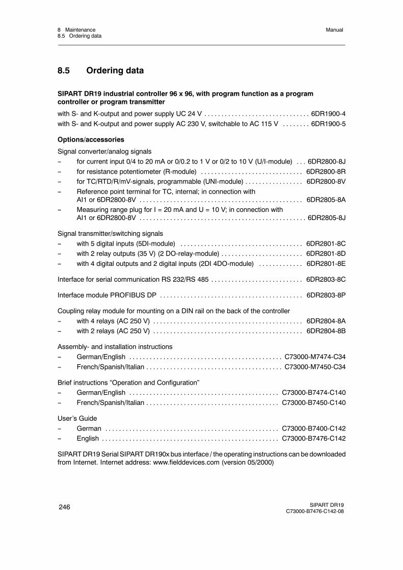
8 Maintenance8.5 Ordering data
Manual
246 SIPART DR19C73000-B7476-C142-08
8.5 Ordering data
SIPART DR19 industrial controller 96 x 96, with program function as a programcontroller or program transmitter
with S- and K-output and power supply UC 24 V 6DR1900-4. . . . . . . . . . . . . . . . . . . . . . . . . . . . . . .with S- and K-output and power supply AC 230 V, switchable to AC 115 V 6DR1900-5. . . . . . . .
Options/accessories
Signal converter/analog signals-- for current input 0/4 to 20 mA or 0/0.2 to 1 V or 0/2 to 10 V (U/I-module) 6DR2800-8J. . .-- for resistance potentiometer (R-module) 6DR2800-8R. . . . . . . . . . . . . . . . . . . . . . . . . . . . . .-- for TC/RTD/R/mV-signals, programmable (UNI-module) 6DR2800-8V. . . . . . . . . . . . . . . . .-- Reference point terminal for TC, internal; in connection with
AI1 or 6DR2800-8V 6DR2805-8A. . . . . . . . . . . . . . . . . . . . . . . . . . . . . . . . . . . . . . . . . . . . . . . .-- Measuring range plug for I = 20 mA and U = 10 V; in connection with
AI1 or 6DR2800-8V 6DR2805-8J. . . . . . . . . . . . . . . . . . . . . . . . . . . . . . . . . . . . . . . . . . . . . . . . .
Signal transmitter/switching signals-- with 5 digital inputs (5DI-module) 6DR2801-8C. . . . . . . . . . . . . . . . . . . . . . . . . . . . . . . . . . . .-- with 2 relay outputs (35 V) (2 DO-relay-module) 6DR2801-8D. . . . . . . . . . . . . . . . . . . . . . . .-- with 4 digital outputs and 2 digital inputs (2DI 4DO-module) 6DR2801-8E. . . . . . . . . . . . .
Interface for serial communication RS 232/RS 485 6DR2803-8C. . . . . . . . . . . . . . . . . . . . . . . . . . .
Interface module PROFIBUS DP 6DR2803-8P. . . . . . . . . . . . . . . . . . . . . . . . . . . . . . . . . . . . . . . . . .
Coupling relay module for mounting on a DIN rail on the back of the controller-- with 4 relays (AC 250 V) 6DR2804-8A. . . . . . . . . . . . . . . . . . . . . . . . . . . . . . . . . . . . . . . . . . . .-- with 2 relays (AC 250 V) 6DR2804-8B. . . . . . . . . . . . . . . . . . . . . . . . . . . . . . . . . . . . . . . . . . . .
Assembly- and installation instructions-- German/English C73000-M7474-C34. . . . . . . . . . . . . . . . . . . . . . . . . . . . . . . . . . . . . . . . . . . . .-- French/Spanish/Italian C73000-M7450-C34. . . . . . . . . . . . . . . . . . . . . . . . . . . . . . . . . . . . . . . .
Brief instructions “Operation and Configuration”-- German/English C73000-B7474-C140. . . . . . . . . . . . . . . . . . . . . . . . . . . . . . . . . . . . . . . . . . . .-- French/Spanish/Italian C73000-B7450-C140. . . . . . . . . . . . . . . . . . . . . . . . . . . . . . . . . . . . . . .
User’s Guide-- German C73000-B7400-C142. . . . . . . . . . . . . . . . . . . . . . . . . . . . . . . . . . . . . . . . . . . . . . . . . . .-- English C73000-B7476-C142. . . . . . . . . . . . . . . . . . . . . . . . . . . . . . . . . . . . . . . . . . . . . . . . . . . .
SIPARTDR19Serial SIPARTDR190x bus interface / theoperating instructions can bedownloadedfrom Internet. Internet address: www.fielddevices.com (version 05/2000)
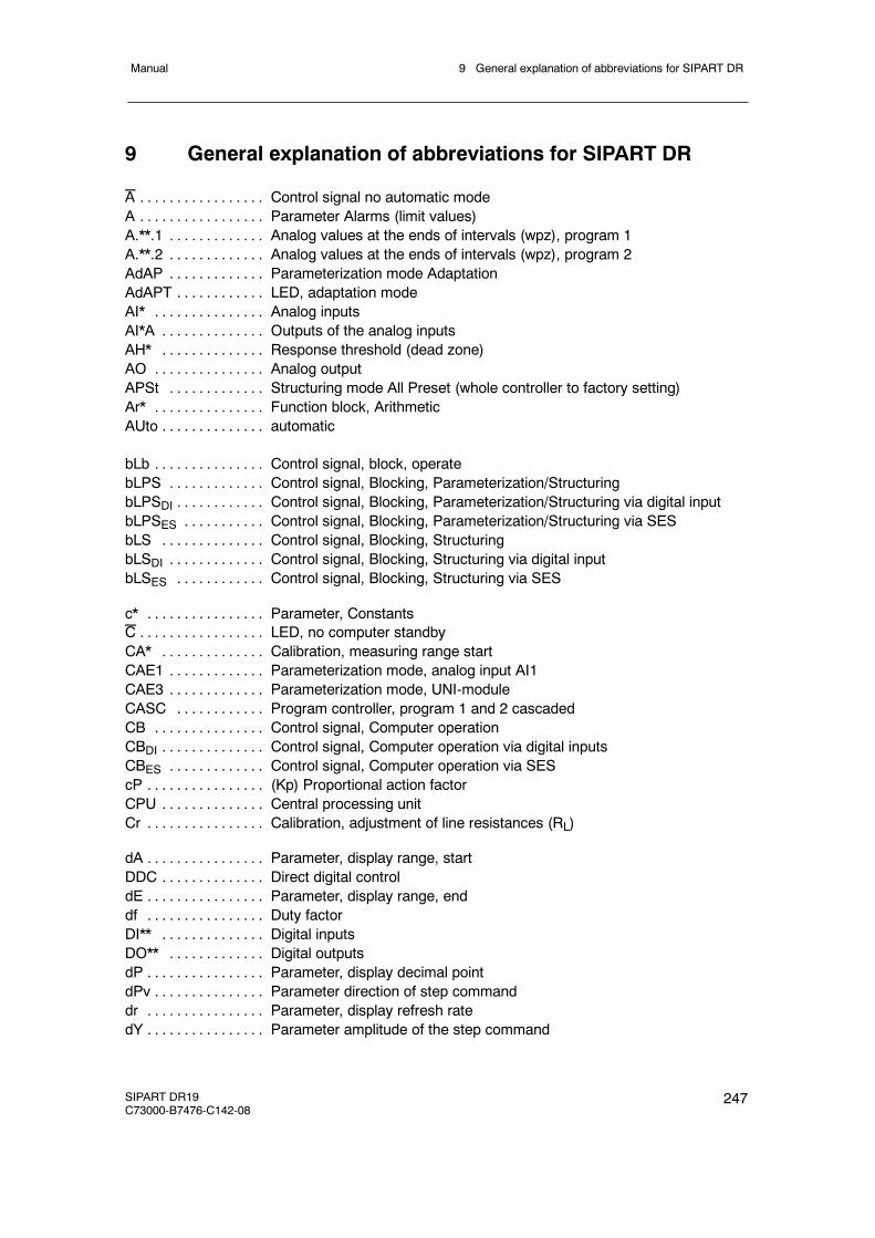
9 General explanation of abbreviations for SIPART DRManual
SIPART DR19C73000-B7476-C142-08
247
9 General explanation of abbreviations for SIPART DR
A Control signal no automatic mode. . . . . . . . . . . . . . . . .A Parameter Alarms (limit values). . . . . . . . . . . . . . . . .A.**.1 Analog values at the ends of intervals (wpz), program 1. . . . . . . . . . . . .A.**.2 Analog values at the ends of intervals (wpz), program 2. . . . . . . . . . . . .AdAP Parameterization mode Adaptation. . . . . . . . . . . . .AdAPT LED, adaptation mode. . . . . . . . . . . .AI* Analog inputs. . . . . . . . . . . . . . .AI*A Outputs of the analog inputs. . . . . . . . . . . . . .AH* Response threshold (dead zone). . . . . . . . . . . . . .AO Analog output. . . . . . . . . . . . . . .APSt Structuring mode All Preset (whole controller to factory setting). . . . . . . . . . . . .Ar* Function block, Arithmetic. . . . . . . . . . . . . . .AUto automatic. . . . . . . . . . . . . .
bLb Control signal, block, operate. . . . . . . . . . . . . . .bLPS Control signal, Blocking, Parameterization/Structuring. . . . . . . . . . . . .bLPSDI Control signal, Blocking, Parameterization/Structuring via digital input. . . . . . . . . . . .bLPSES Control signal, Blocking, Parameterization/Structuring via SES. . . . . . . . . . .bLS Control signal, Blocking, Structuring. . . . . . . . . . . . . .bLSDI Control signal, Blocking, Structuring via digital input. . . . . . . . . . . . .bLSES Control signal, Blocking, Structuring via SES. . . . . . . . . . . .
c* Parameter, Constants. . . . . . . . . . . . . . . .C LED, no computer standby. . . . . . . . . . . . . . . . .CA* Calibration, measuring range start. . . . . . . . . . . . . .CAE1 Parameterization mode, analog input AI1. . . . . . . . . . . . .CAE3 Parameterization mode, UNI-module. . . . . . . . . . . . .CASC Program controller, program 1 and 2 cascaded. . . . . . . . . . . .CB Control signal, Computer operation. . . . . . . . . . . . . . .CBDI Control signal, Computer operation via digital inputs. . . . . . . . . . . . . .CBES Control signal, Computer operation via SES. . . . . . . . . . . . .cP (Kp) Proportional action factor. . . . . . . . . . . . . . . .CPU Central processing unit. . . . . . . . . . . . . .Cr Calibration, adjustment of line resistances (RL). . . . . . . . . . . . . . . .
dA Parameter, display range, start. . . . . . . . . . . . . . . .DDC Direct digital control. . . . . . . . . . . . . .dE Parameter, display range, end. . . . . . . . . . . . . . . .df Duty factor. . . . . . . . . . . . . . . .DI** Digital inputs. . . . . . . . . . . . . .DO** Digital outputs. . . . . . . . . . . . .dP Parameter, display decimal point. . . . . . . . . . . . . . . .dPv Parameter direction of step command. . . . . . . . . . . . . . .dr Parameter, display refresh rate. . . . . . . . . . . . . . . .dY Parameter amplitude of the step command. . . . . . . . . . . . . . . .
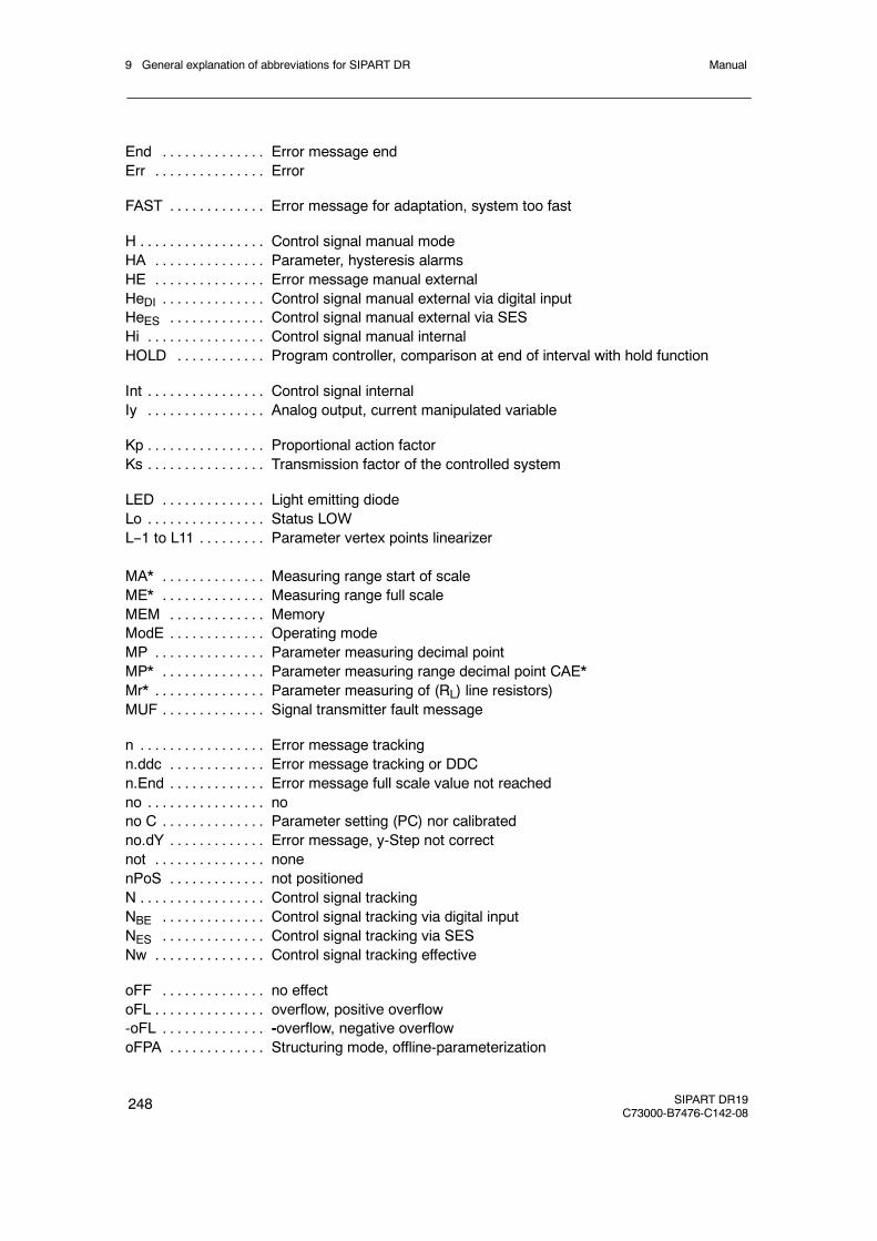
9 General explanation of abbreviations for SIPART DR Manual
248 SIPART DR19C73000-B7476-C142-08
End Error message end. . . . . . . . . . . . . .Err Error. . . . . . . . . . . . . . .
FAST Error message for adaptation, system too fast. . . . . . . . . . . . .
H Control signal manual mode. . . . . . . . . . . . . . . . .HA Parameter, hysteresis alarms. . . . . . . . . . . . . . .HE Error message manual external. . . . . . . . . . . . . . .HeDI Control signal manual external via digital input. . . . . . . . . . . . . .HeES Control signal manual external via SES. . . . . . . . . . . . .Hi Control signal manual internal. . . . . . . . . . . . . . . .HOLD Program controller, comparison at end of interval with hold function. . . . . . . . . . . .
Int Control signal internal. . . . . . . . . . . . . . . .Iy Analog output, current manipulated variable. . . . . . . . . . . . . . . .
Kp Proportional action factor. . . . . . . . . . . . . . . .Ks Transmission factor of the controlled system. . . . . . . . . . . . . . . .
LED Light emitting diode. . . . . . . . . . . . . .Lo Status LOW. . . . . . . . . . . . . . . .L--1 to L11 Parameter vertex points linearizer. . . . . . . . .
MA* Measuring range start of scale. . . . . . . . . . . . . .ME* Measuring range full scale. . . . . . . . . . . . . .MEM Memory. . . . . . . . . . . . .ModE Operating mode. . . . . . . . . . . . .MP Parameter measuring decimal point. . . . . . . . . . . . . . .MP* Parameter measuring range decimal point CAE*. . . . . . . . . . . . . .Mr* Parameter measuring of (RL) line resistors). . . . . . . . . . . . . . .MUF Signal transmitter fault message. . . . . . . . . . . . . .
n Error message tracking. . . . . . . . . . . . . . . . .n.ddc Error message tracking or DDC. . . . . . . . . . . . .n.End Error message full scale value not reached. . . . . . . . . . . . .no no. . . . . . . . . . . . . . . .no C Parameter setting (PC) nor calibrated. . . . . . . . . . . . . .no.dY Error message, y-Step not correct. . . . . . . . . . . . .not none. . . . . . . . . . . . . . .nPoS not positioned. . . . . . . . . . . . .N Control signal tracking. . . . . . . . . . . . . . . . .NBE Control signal tracking via digital input. . . . . . . . . . . . . .NES Control signal tracking via SES. . . . . . . . . . . . . .Nw Control signal tracking effective. . . . . . . . . . . . . . .
oFF no effect. . . . . . . . . . . . . .oFL overflow, positive overflow. . . . . . . . . . . . . . .-oFL -overflow, negative overflow. . . . . . . . . . . . . .oFPA Structuring mode, offline-parameterization. . . . . . . . . . . . .
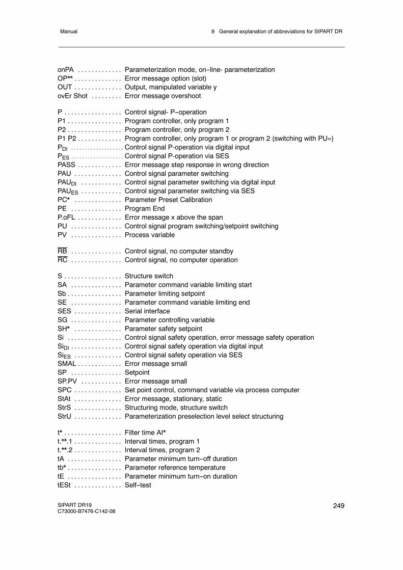
9 General explanation of abbreviations for SIPART DRManual
SIPART DR19C73000-B7476-C142-08
249
onPA Parameterization mode, on--line- parameterization. . . . . . . . . . . . .OP** Error message option (slot). . . . . . . . . . . . . .OUT Output, manipulated variable y. . . . . . . . . . . . . .ovEr Shot Error message overshoot. . . . . . . . .
P Control signal- P--operation. . . . . . . . . . . . . . . . .P1 Program controller, only program 1. . . . . . . . . . . . . . . .P2 Program controller, only program 2. . . . . . . . . . . . . . . .P1 P2 Program controller, only program 1 or program 2 (switching with PU=). . . . . . . . . . . . .PDI Control signal P-operation via digital input. . . . . . . . . . . . . . . . . . .
PES Control signal P-operation via SES. . . . . . . . . . . . . . . . . . .
PASS Error message step response in wrong direction. . . . . . . . . . . . .PAU Control signal parameter switching. . . . . . . . . . . . . .PAUDI Control signal parameter switching via digital input. . . . . . . . . . . .PAUES Control signal parameter switching via SES. . . . . . . . . . . .PC* Parameter Preset Calibration. . . . . . . . . . . . . .PE Program End. . . . . . . . . . . . . . .P.oFL Error message x above the span. . . . . . . . . . . . .PU Control signal program switching/setpoint switching. . . . . . . . . . . . . . .PV Process variable. . . . . . . . . . . . . . .
RB Control signal, no computer standby. . . . . . . . . . . . . . .RC Control signal, no computer operation. . . . . . . . . . . . . . .
S Structure switch. . . . . . . . . . . . . . . . .SA Parameter command variable limiting start. . . . . . . . . . . . . . .Sb Parameter limiting setpoint. . . . . . . . . . . . . . . .SE Parameter command variable limiting end. . . . . . . . . . . . . . .SES Serial interface. . . . . . . . . . . . . .SG Parameter controlling variable. . . . . . . . . . . . . . .SH* Parameter safety setpoint. . . . . . . . . . . . . .Si Control signal safety operation, error message safety operation. . . . . . . . . . . . . . . .SiDI Control signal safety operation via digital input. . . . . . . . . . . . . . .SiES Control signal safety operation via SES. . . . . . . . . . . . . .SMAL Error message small. . . . . . . . . . . . .SP Setpoint. . . . . . . . . . . . . . .SP.PV Error message small. . . . . . . . . . . .SPC Set point control, command variable via process computer. . . . . . . . . . . . . .StAt Error message, stationary, static. . . . . . . . . . . . . .StrS Structuring mode, structure switch. . . . . . . . . . . . . .StrU Parameterization preselection level select structuring. . . . . . . . . . . . . .
t* Filter time AI*. . . . . . . . . . . . . . . . .t.**.1 Interval times, program 1. . . . . . . . . . . . . .t.**.2 Interval times, program 2. . . . . . . . . . . . . .tA Parameter minimum turn--off duration. . . . . . . . . . . . . . . .tb* Parameter reference temperature. . . . . . . . . . . . . . . .tE Parameter minimum turn--on duration. . . . . . . . . . . . . . . .tESt Self--test. . . . . . . . . . . . . .
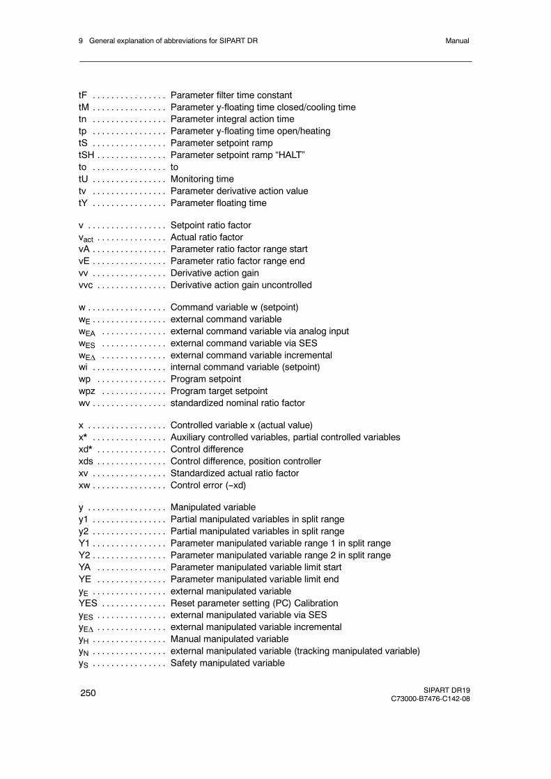
9 General explanation of abbreviations for SIPART DR Manual
250 SIPART DR19C73000-B7476-C142-08
tF Parameter filter time constant. . . . . . . . . . . . . . . .tM Parameter y-floating time closed/cooling time. . . . . . . . . . . . . . . .tn Parameter integral action time. . . . . . . . . . . . . . . .tp Parameter y-floating time open/heating. . . . . . . . . . . . . . . .tS Parameter setpoint ramp. . . . . . . . . . . . . . . .tSH Parameter setpoint ramp “HALT”. . . . . . . . . . . . . . .to to. . . . . . . . . . . . . . . .tU Monitoring time. . . . . . . . . . . . . . . .tv Parameter derivative action value. . . . . . . . . . . . . . . .tY Parameter floating time. . . . . . . . . . . . . . . .
v Setpoint ratio factor. . . . . . . . . . . . . . . . .vact Actual ratio factor. . . . . . . . . . . . . . .vA Parameter ratio factor range start. . . . . . . . . . . . . . . .vE Parameter ratio factor range end. . . . . . . . . . . . . . . .vv Derivative action gain. . . . . . . . . . . . . . . .vvc Derivative action gain uncontrolled. . . . . . . . . . . . . . .
w Command variable w (setpoint). . . . . . . . . . . . . . . . .wE external command variable. . . . . . . . . . . . . . . .wEA external command variable via analog input. . . . . . . . . . . . . .wES external command variable via SES. . . . . . . . . . . . . .wEΔ external command variable incremental. . . . . . . . . . . . . .wi internal command variable (setpoint). . . . . . . . . . . . . . . .wp Program setpoint. . . . . . . . . . . . . . .wpz Program target setpoint. . . . . . . . . . . . . .wv standardized nominal ratio factor. . . . . . . . . . . . . . . .
x Controlled variable x (actual value). . . . . . . . . . . . . . . . .x* Auxiliary controlled variables, partial controlled variables. . . . . . . . . . . . . . . .xd* Control difference. . . . . . . . . . . . . . .xds Control difference, position controller. . . . . . . . . . . . . . .xv Standardized actual ratio factor. . . . . . . . . . . . . . . .xw Control error (--xd). . . . . . . . . . . . . . . .
y Manipulated variable. . . . . . . . . . . . . . . . .y1 Partial manipulated variables in split range. . . . . . . . . . . . . . . .y2 Partial manipulated variables in split range. . . . . . . . . . . . . . . .Y1 Parameter manipulated variable range 1 in split range. . . . . . . . . . . . . . . .Y2 Parameter manipulated variable range 2 in split range. . . . . . . . . . . . . . . .YA Parameter manipulated variable limit start. . . . . . . . . . . . . . .YE Parameter manipulated variable limit end. . . . . . . . . . . . . . .yE external manipulated variable. . . . . . . . . . . . . . . .YES Reset parameter setting (PC) Calibration. . . . . . . . . . . . . .yES external manipulated variable via SES. . . . . . . . . . . . . . .yEΔ external manipulated variable incremental. . . . . . . . . . . . . . .yH Manual manipulated variable. . . . . . . . . . . . . . . .yN external manipulated variable (tracking manipulated variable). . . . . . . . . . . . . . . .yS Safety manipulated variable. . . . . . . . . . . . . . . .
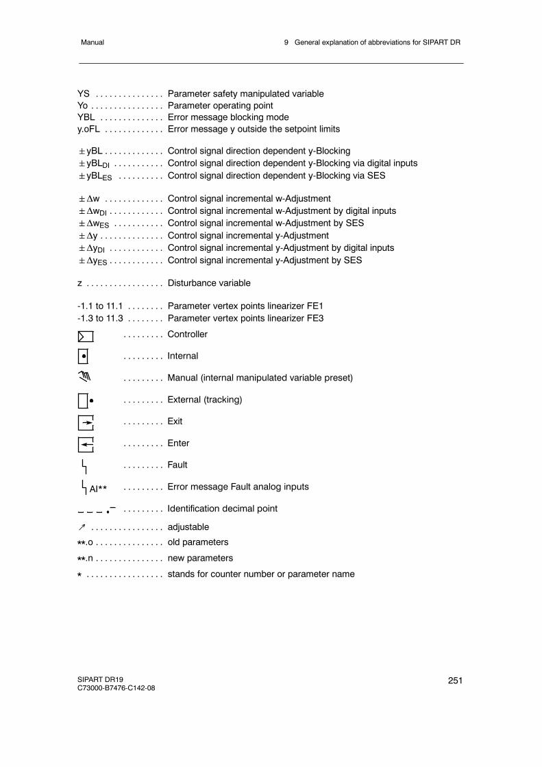
9 General explanation of abbreviations for SIPART DRManual
SIPART DR19C73000-B7476-C142-08
251
YS Parameter safety manipulated variable. . . . . . . . . . . . . . .Yo Parameter operating point. . . . . . . . . . . . . . . .YBL Error message blocking mode. . . . . . . . . . . . . .y.oFL Error message y outside the setpoint limits. . . . . . . . . . . . .
yBL Control signal direction dependent y-Blocking. . . . . . . . . . . . .yBLDI Control signal direction dependent y-Blocking via digital inputs. . . . . . . . . . .yBLES Control signal direction dependent y-Blocking via SES. . . . . . . . . .
Δw Control signal incremental w-Adjustment. . . . . . . . . . . . .ΔwDI Control signal incremental w-Adjustment by digital inputs. . . . . . . . . . . .ΔwES Control signal incremental w-Adjustment by SES. . . . . . . . . . .Δy Control signal incremental y-Adjustment. . . . . . . . . . . . . .ΔyDI Control signal incremental y-Adjustment by digital inputs. . . . . . . . . . . .ΔyES Control signal incremental y-Adjustment by SES. . . . . . . . . . . .
z Disturbance variable. . . . . . . . . . . . . . . . .
-1.1 to 11.1 Parameter vertex points linearizer FE1. . . . . . . .-1.3 to 11.3 Parameter vertex points linearizer FE3. . . . . . . .
Controller. . . . . . . . .
Internal. . . . . . . . .
Manual (internal manipulated variable preset). . . . . . . . .
External (tracking). . . . . . . . .
Exit. . . . . . . . .
Enter. . . . . . . . .
Fault. . . . . . . . .
Error message Fault analog inputs. . . . . . . . .
Identification decimal point. . . . . . . . .
AI**
↗ adjustable. . . . . . . . . . . . . . . .
**.o old parameters. . . . . . . . . . . . . . .
**.n new parameters. . . . . . . . . . . . . . .
* stands for counter number or parameter name. . . . . . . . . . . . . . . . .

9 General explanation of abbreviations for SIPART DR Manual
252 SIPART DR19C73000-B7476-C142-08
Manual
SIPART DR19C73000-B7476-C142-08
253
Index
Numbers
6DR190x--4, Connection, 1386DR190x--5, Connection, 1386DR2800--8J
Connection, 143Connection example, 147Function principle of the option modules, 31Technical Data, 44
6DR2800--8RConnection, 144Function principle of the option modules, 31Technical Data, 44
6DR2800--8VConnection, 145Function principle of the option modules, 32Technical Data, 45
6DR2801--8C, 152Function principle of the option modules, 33Technical Data, 47
6DR2801--8D, 153Function principle of the option modules, 33Technical Data, 46
6DR2801--8E, 152Function principle of the option modules, 33Technical Data, 47
6DR2803--8C, 154Function principle of the option modules, 35Technical Data, 48
6DR2803--8P, 156Connection, 157Function principle of the option modules, 34Technical Data, 47
6DR2804--8A, 1536DR2804--8A/B, Technical Data, 496DR2804--8B, 1536DR2805--8A, Function principle of the optionmodules, 326DR2805--8J, 139, 145
Function principle of the option modules, 32Technical Data, 46
A
A/D converter, Technical Data, 42
A1 to A4, Digital outputs, Features, 24Actual value, 160Actual value display, Functional explanation,62Actuating time tp and tM, 101AdAP, Configuration mode, 169Adaptation, 120
Aborted, 170Condition, 169Error messages, 172
Adaptation principle, 121Adaptation requirements, 120Adaptive filter, 123, 207Alarm LED, 161Analog input, Universal module, 145Analog inputs
Features, 21Functional principle of the standard control-ler, 28Technical Data, 40
Analog output signal processing (S56), 117Analog outputs, Technical Data, 41AO, Connection, 141Application examples, 211Application Range, 20APSt, 201
Configuration, 30Assembly, 129Automatic mode, Controller output structure,114
B
Backplane moduleRemoval, 129Replacing, 243
Backplane module with power supply unit, De-sign, 26bLb
Digital inputs, Features, 22Functional explanation, 58Operating locks, 159
Block diagram, 137

Manual
254 SIPART DR19C73000-B7476-C142-08
bLPSDigital inputs, Features, 22Functional explanation, 58Operating locks, 159
bLSDigital inputs, Features, 22Functional explanation, 58
bLS, Operating locks, 159
C
CAE1, Set analog input AI1, 191CAE3, Set UNI--module, 196Cascade controls, 71CB
Digital inputs, Features, 23Functional explanation, 58
Changing the scales, 131Changing the tag plate, 131CLb, Digital outputs, Features, 24CLFo, Clock format, 94Clock format CLFo, 94Clock parameters, 93CLPA
Clock parameters, 93Configuration mode, 176
Commissioning, 203Configuration, Functional principle of the stan-dard controller, 29Configuration examples, 226Configuration mode, 159, 166
AdAP (adaptation), 169CLPA (program controller), 176oFPA (offline parameters), 173onPA (online parameters), 167StrS (structure switch), 180
Configuring the controller, Application exam-ples, 211Configuring tool, 234
for structuring, 239to oFPA, 237to onPA, 236
Connecting elements, Arrangement, 134Connection
6DR190x--5, 1386DR1910x--4, 138
6DR2800--8J, 1436DR2800--8R, 1446DR2800--8V, 145AO, 141Options modules, 143DI1 to DI2, 141DO1 to DO2, 142Electrical, 134Examples, 147Ground, 136Interface module, 154Measuring lines, 135, 139PE conductor, 134Power supply, 134, 138PROFIBUS--DP, 157RS 232, 154Signal lines, 135, 139Standard controller, 138
Connection technique, Design, 26Constants c1 to c7, Functional explanation, 61Control algorithm, 98Control difference, 160Control parameters
automatic setting, 208Setting by the adaptation method, 208
Control signalsfor setpoint switching, 72Functional explanation, 58, 61
Display range, Functional explanation, 63Control system coupling, 96, 97
via serial interface, 115Control unit, 82, 84Controlled ratio controller, 76Controlled system with compensation, Trans-ient function, 210Controlled variable processing, 72Controller, installing, 132Controller direction of effect, 98
Adaptation to controlled system, 203Controller output structure
S2=0, 101S2=1, 102S2=2, 106S2=3, 109
Controller output structures, 101Controller types, 59
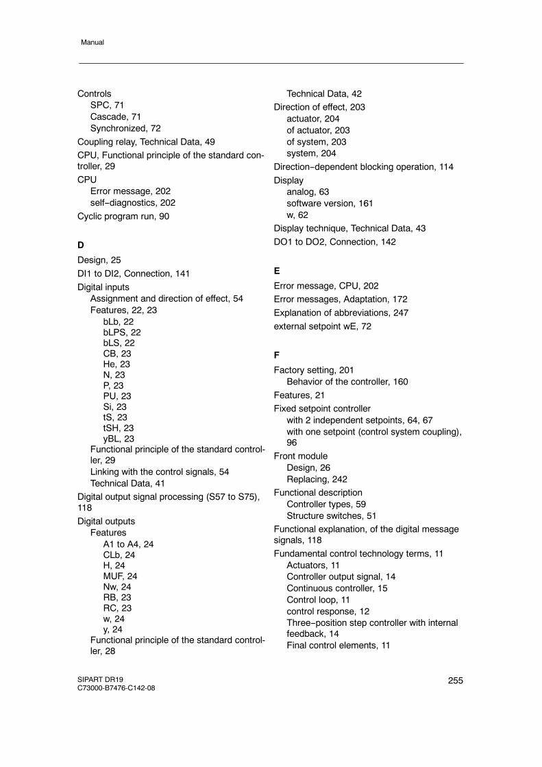
Manual
SIPART DR19C73000-B7476-C142-08
255
ControlsSPC, 71Cascade, 71Synchronized, 72
Coupling relay, Technical Data, 49CPU, Functional principle of the standard con-troller, 29CPU
Error message, 202self--diagnostics, 202
Cyclic program run, 90
D
Design, 25DI1 to DI2, Connection, 141Digital inputs
Assignment and direction of effect, 54Features, 22, 23
bLb, 22bLPS, 22bLS, 22CB, 23He, 23N, 23P, 23PU, 23Si, 23tS, 23tSH, 23yBL, 23
Functional principle of the standard control-ler, 29Linking with the control signals, 54Technical Data, 41
Digital output signal processing (S57 to S75),118Digital outputs
FeaturesA1 to A4, 24CLb, 24H, 24MUF, 24Nw, 24RB, 23RC, 23w, 24y, 24
Functional principle of the standard control-ler, 28
Technical Data, 42Direction of effect, 203
actuator, 204of actuator, 203of system, 203system, 204
Direction--dependent blocking operation, 114Display
analog, 63software version, 161w, 62
Display technique, Technical Data, 43DO1 to DO2, Connection, 142
E
Error message, CPU, 202Error messages, Adaptation, 172Explanation of abbreviations, 247external setpoint wE, 72
F
Factory setting, 201Behavior of the controller, 160
Features, 21Fixed setpoint controller
with 2 independent setpoints, 64, 67with one setpoint (control system coupling),96
Front moduleDesign, 26Replacing, 242
Functional descriptionController types, 59Structure switches, 51
Functional explanation, of the digital messagesignals, 118Fundamental control technology terms, 11
Actuators, 11Controller output signal, 14Continuous controller, 15Control loop, 11control response, 12Three--position step controller with internalfeedback, 14Final control elements, 11
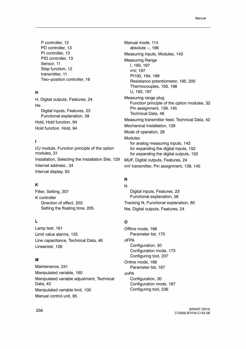
Manual
256 SIPART DR19C73000-B7476-C142-08
P controller, 12PD controller, 13PI controller, 13PID controller, 13Sensor, 11Step function, 12transmitter, 11Two--position controller, 16
H
H, Digital outputs, Features, 24He
Digital inputs, Features, 23Functional explanation, 58
Hold, Hold function, 94Hold function Hold, 94
I
I/U module, Function principle of the optionmodules, 31Installation, Selecting the Installation Site, 129Internet address:, 34Interval display, 93
K
Filter, Setting, 207K controller
Direction of effect, 203Setting the floating time, 205
L
Lamp test, 161Limit value alarms, 125Line capacitance, Technical Data, 48Linearizer, 126
M
Maintenance, 241Manipulated variable, 160Manipulated variable adjustment, TechnicalData, 43Manipulated variable limit, 100Manual control unit, 85
Manual mode, 114absolute ~, 166
Measuring inputs, Modules, 143Measuring Range
I, 193, 197mV, 197Pt100, 194, 199Resistance potentiometer, 195, 200Thermocouples, 193, 198U, 193, 197
Measuring range plugFunction principle of the option modules, 32Pin assignment, 139, 145Technical Data, 46
Measuring transmitter feed, Technical Data, 42Mechanical Installation, 129Mode of operation, 28Modules
for analog measuring inputs, 143for expanding the digital inputs, 152for expanding the digital outputs, 152
MUF, Digital outputs, Features, 24mV transmitter, Pin assignment, 139, 145
N
NDigital inputs, Features, 23Functional explanation, 58
Tracking N, Functional explanation, 60Nw, Digital outputs, Features, 24
O
Offline mode, 166Parameter list, 175
oFPAConfiguration, 30Configuration mode, 173Configuring tool, 237
Online mode, 166Parameter list, 167
onPAConfiguration, 30Configuration mode, 167Configuring tool, 236

Manual
SIPART DR19C73000-B7476-C142-08
257
Operating locks, 159bLb, 159bLPS, 159bLS, 159
Operating pointautomatic, 100fixed, 100y0 in P--controller, 100
Operation, 159Operation mode
Configuration mode, 159Process operation mode, 159Selection mode, 159
Operation with 2 or 3 setpoints, 72Options modules
Assembly, 133Connection, 143Mode of operation, 31Replacing, 242
Ordering data, 246Output signal processing
analog, 117digital, 118
Output structure, Features, 21Outputs for the manipulated variable Y, Func-tional principle of the standard controller, 28
P
PDigital inputs, Features, 23Functional explanation, 58
P--controller, 98Setting, 208
Parameter listCLPA, 177oFPA (offline parameters), 175onPA (online parameters), 167
Parameters, Technical Data, 43PD--controller, Setting, 208PI--controller, 98PI--controller, Setting, 209PID controller, Setting, 209Pin assignment
Measuring range plug, 139, 145mV transmitter, 139, 145Pt100 sensor, 140, 146
Resistance potentiometer, 141, 147Thermocouples, 140, 146
Power supply, Standard controller, 39Power supply unit
Features, 22Functional principle of the standard control-ler, 29
Process display, 82Process operation mode, 159, 160PROFIBUS DP, 128
Technical Data, 47PROFIBUS--DP, 156
Connection, 157Structure switches, 190
Program controller, 89Configuration example, 217Display, 161Operation, 161
Program end, Operating modes, 90Program run, cyclic, 90Program selection PrSE, 93Program transmitter, 89
Configuration example, 217PrSE, Program selection, 93PT100, Measuring Range, 194, 199Pt100 sensor, Pin assignment, 140, 146PU
Digital inputs, Features, 23Setpoint, 58
R
R, 141, 147R module, Function principle of the option mo-dules, 31Ratio controller
controlled, 76Example, 79
RB, Digital outputs, Features, 23RC, Digital outputs, Features, 23Rear of controller, 129reference point, Function principle of the optionmodules, 32Relay contacts, unlock, 130Replacing
Backplane module, 243
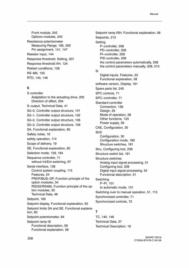
Manual
258 SIPART DR19C73000-B7476-C142-08
Front module, 242Options modules, 242
Resistance potentiometerMeasuring Range, 195, 200Pin assignment, 141, 147
Resistor input, 144Response threshold, Setting, 207Response threshold AH, 124Restart conditions, 128RS 485, 155RTD, 140, 146
S
S controllerAdaptation to the actuating drive, 205Direction of effect, 204
S--output, Technical Data, 41S2=0, Controller output structure, 101S2=1, Controller output structure, 102S2=2, Controller output structure, 106S2=3, Controller output structure, 109SA, Functional explanation, 60Safety notes, 19safety operation, 114Scope of delivery, 19SE, Functional explanation, 60Selection mode, 159, 164Sequence controller, 71
without Int/Ext switching, 97Serial interface, 128
Control system coupling, 115Features, 24PROFIBUS--DP, Function principle of theoption modules, 34RS232/RS485, Function principle of the op-tion modules, 35Technical Data, 48
Setpoint, 160Setpoint display, Functional explanation, 62Setpoint limits SA and SE, Functional explana-tion, 60Setpoint potentiometer, 84Setpoint ramp tS
Functional description, 59Functional explanation, 58
Setpoint ramp tSH, Functional explanation, 58Setpoints, 213Setting
P--controller, 208PD--controller, 208PI--controller, 209PID controller, 209the control parameters automatically, 208the control parameters manually, 208, 210
SiDigital inputs, Features, 23Functional explanation, 58
software version, Display, 161Spare parts list, 245SPC controls, 71SPC--controller, 71Standard controller
Connection, 138Design, 25Mode of operation, 28Other functions, 123Power supply, 39
CAE, Configuration, 30StrS
Configuration, 30Configuration mode, 180Structure switches, 181
Stru, Configuring tool, 239Structure switch list, 181Structure switches
Analog input signal processing, 51Configuring tool, 239Digital input signal processing, 54Functional description, 51
SwitchingP--PI, 101to automatic mode, 101
Switching over to manual operation, 51, 115Synchronized controller, 71Synchronized controls, 72
T
TC, 140, 146Technical Data, 37Technical Description, 19
Manual
SIPART DR19C73000-B7476-C142-08
259
ThermocouplesMeasuring Range, 193, 198Pin assignment, 140, 146
Time display, 93Tracking operation, 114Transient function, of a controlled system withcompensation, 210Transmitter fault, Switching over to manualoperation, 51, 115tS
Digital inputs, Features, 23Functional description, 59Functional explanation, 58
tSHDigital inputs, Features, 23Functional explanation, 58
U
UNI module:Function principle of the option modules, 32Technical Data, 45
Universal module for analog input, 145
V
Voltage output, Features, 22
W
w, Digital outputs, Features, 24wE, 72wi
Functional description, 59Manual setpoint setting, 59
Work prior to installation, 129Working with different setpoints, 213wvi, Nominal ratio setting, 59
X
x--tracking (S43), Functional explanation, 60
Y
y, Digital outputs, Features, 24y display, 63, 105
Source and direction of effect, 115yBL
Digital inputs, Features, 23Functional explanation, 58
Z
zD, 98zy, 98

Manual
260 SIPART DR19C73000-B7476-C142-08