termo 7 ca 05 1
TRANSCRIPT
5-1
Solutions Manual for
Thermodynamics: An Engineering Approach Seventh Edition
Yunus A. Cengel, Michael A. Boles McGraw-Hill, 2011
Chapter 5 MASS AND ENERGY ANALYSIS OF
CONTROL VOLUMES
PROPRIETARY AND CONFIDENTIAL This Manual is the proprietary property of The McGraw-Hill Companies, Inc. (“McGraw-Hill”) and protected by copyright and other state and federal laws. By opening and using this Manual the user agrees to the following restrictions, and if the recipient does not agree to these restrictions, the Manual should be promptly returned unopened to McGraw-Hill: This Manual is being provided only to authorized professors and instructors for use in preparing for the classes using the affiliated textbook. No other use or distribution of this Manual is permitted. This Manual may not be sold and may not be distributed to or used by any student or other third party. No part of this Manual may be reproduced, displayed or distributed in any form or by any means, electronic or otherwise, without the prior written permission of McGraw-Hill.
PROPRIETARY MATERIALpreparation. If you are a student using this Manual, you are using it without permission.
. © 2011 The McGraw-Hill Companies, Inc. Limited distribution permitted only to teachers and educators for course
5-2
Conservation of Mass
5-1C Mass flow rate is the amount of mass flowing through a cross-section per unit time whereas the volume flow rate is the amount of volume flowing through a cross-section per unit time.
5-2C Flow through a control volume is steady when it involves no changes with time at any specified position.
5-3C The amount of mass or energy entering a control volume does not have to be equal to the amount of mass or energy leaving during an unsteady-flow process.
5-4C No, a flow with the same volume flow rate at the inlet and the exit is not necessarily steady (unless the density is constant). To be steady, the mass flow rate through the device must remain constant.
5-5E A pneumatic accumulator arranged to maintain a constant pressure as air enters or leaves is considered. The amount of air added is to be determined.
Assumptions 1 Air is an ideal gas.
Properties The gas constant of air is R = 0.3704 psia⋅ft3/lbm⋅R (Table A-1E).
Analysis At the beginning of the filling, the mass of the air in the container is
lbm 200.0R) 460R)(80/lbmftpsia 3704.0(
)ft psia)(0.2 200(3
3
1
111 =
+⋅⋅==
RTP
mV
During the process both pressure and temperature remain constant while volume increases by 5 times. Thus,
lbm 00.1)200.0(55 12
222 ==== m
RTP
mV
The amount of air added to the container is then
lbm 0.8=−=−=∆ 200.000.112 mmm
PROPRIETARY MATERIALpreparation. If you are a student using this Manual, you are using it without permission.
. © 2011 The McGraw-Hill Companies, Inc. Limited distribution permitted only to teachers and educators for course
5-3
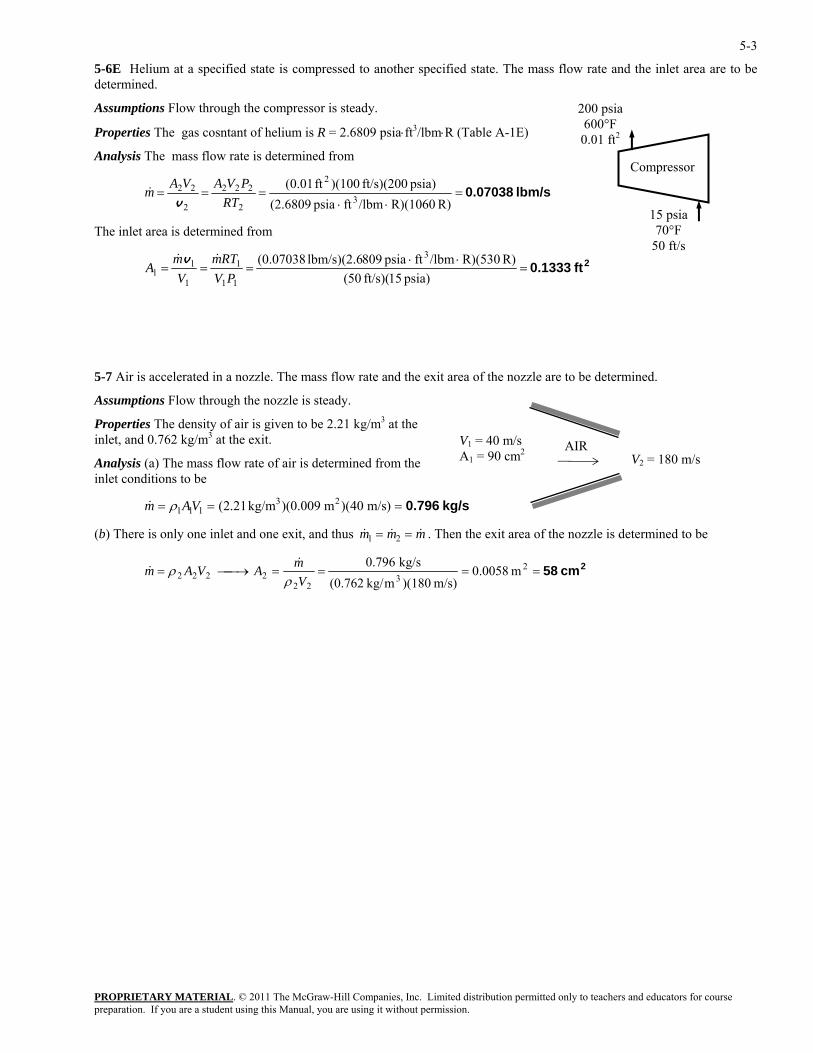
5-6E Helium at a specified state is compressed to another specified state. The mass flow rate and the inlet area are to be determined.
Assumptions Flow through the compressor is steady.
PROPRIETARY MATERIAL. © 2011 The McGraw-Hill Companies, Inc. Limited distribution permitted only to teachers and educators for course
Properties The gas cosntant of helium is R = 2.6809 psia⋅ft3/lbm⋅R (Table A-1E)
Analysis The mass flow rate is determined from
lbm/s 0.07038=⋅⋅
===R) R)(1060/lbmftpsia (2.6809
psia) ft/s)(200 )(100ft 01.0(3
2
2
222
2
22
RTPVAVA
mv
&
The inlet area is determined from
2ft 0.1333=⋅⋅
===psia) 15(ft/s) 50(
R) R)(530/lbmftpsia 809lbm/s)(2.6 (0.07038 3
11
1
1
11 PV
RTmV
mA
&&v
15 psia 70°F
50 ft/s
200 psia 600°F 0.01 ft2
Compressor
5-7 Air is accelerated in a nozzle. The mass flow rate and the exit area of the nozzle are to be determined.
Assumptions Flow through the nozzle is steady.
Properties The density of air is given to be 2.21 kg/m3 at the inlet, and 0.762 kg/m3 at the exit.
Analysis (a) The mass flow rate of air is determined from the inlet conditions to be
kg/s 0.796=== )m/s 04)(m 0.009)(kg/m 21.2( 23111 VAm ρ&
V1 = 40 m/s A1 = 90 cm2
V2 = 180 m/s
AIR
(b) There is only one inlet and one exit, and thus & &m m m1 2 &= = . Then the exit area of the nozzle is determined to be
2cm 58====⎯→⎯= 23
222222 m 0058.0
m/s) )(180mkg/ (0.762kg/s 0.796
VmAVAm
ρρ
&&
preparation. If you are a student using this Manual, you are using it without permission.
5-4
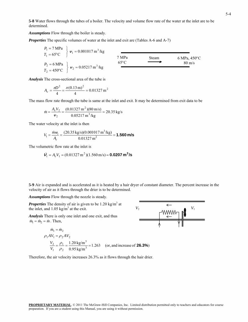
5-8 Water flows through the tubes of a boiler. The velocity and volume flow rate of the water at the inlet are to be determined.
Assumptions Flow through the boiler is steady.
Properties The specific volumes of water at the inlet and exit are (Tables A-6 and A-7)
/kgm 001017.0 C65
MPa 7 31
1
1 =⎭⎬⎫
°==
v TP
6 MPa, 450°C80 m/s
7 MPa65°C
Steam
/kgm 05217.0 C450 MPa 6 3
22
2 =⎭⎬⎫
°==
v TP
Analysis The cross-sectional area of the tube is
222
m 01327.04
m) 13.0(4
===ππDAc
The mass flow rate through the tube is same at the inlet and exit. It may be determined from exit data to be
kg/s 20.35/kgm 0.05217
m/s) 80)(m 01327.0(3
2
2
2 ===v
VAm c&
The water velocity at the inlet is then
m/s 1.560=== 2
31
1 m 01327.0/kg)m 1017kg/s)(0.00 35.20(
cAmV v&
The volumetric flow rate at the inlet is
/sm 0.0207 3=== m/s) )(1.560m 01327.0( 211 VAcV&
5-9 Air is expanded and is accelerated as it is heated by a hair dryer of constant diameter. The percent increase in the velocity of air as it flows through the drier is to be determined.
Assumptions Flow through the nozzle is steady.
PROPRIETARY MATERIAL. © 2011 The McGraw-Hill Companies, Inc. Limited distribution permitted only to teachers and educators for course
Properties The density of air is given to be 1.20 kg/m3 at the inlet, and 1.05 kg/m3 at the exit.
Analysis There is only one inlet and one exit, and thus . Then, & &m m m1 2= = &
)of increase and (or, 1.263kg/m 0.95kg/m 1.20
3
3
2
1
1
2
2211
21
26.3% ===
==
ρρ
ρρ
VV
AVAVmm &&
V2 V1
Therefore, the air velocity increases 26.3% as it flows through the hair drier.
preparation. If you are a student using this Manual, you are using it without permission.
5-5
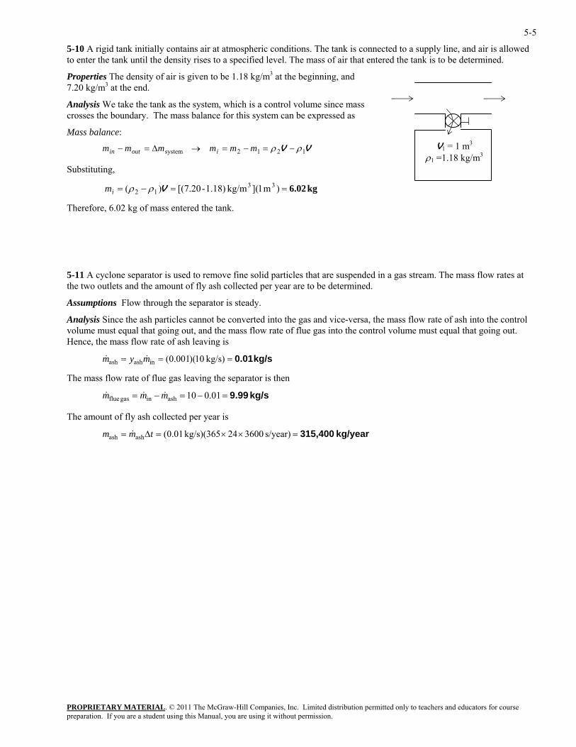
5-10 A rigid tank initially contains air at atmospheric conditions. The tank is connected to a supply line, and air is allowed to enter the tank until the density rises to a specified level. The mass of air that entered the tank is to be determined.
Properties The density of air is given to be 1.18 kg/m3 at the beginning, and 7.20 kg/m3 at the end.
V1 = 1 m3
ρ1 =1.18 kg/m3
Analysis We take the tank as the system, which is a control volume since mass crosses the boundary. The mass balance for this system can be expressed as
Mass balance:
VV 1212system ρρ −=−=→∆=− mmmmmm ioutin
Substituting,
kg 6.02==−= )m 1]( kg/m1.18)-(7.20[)( 3312 Vρρim
Therefore, 6.02 kg of mass entered the tank.
5-11 A cyclone separator is used to remove fine solid particles that are suspended in a gas stream. The mass flow rates at the two outlets and the amount of fly ash collected per year are to be determined.
Assumptions Flow through the separator is steady.
Analysis Since the ash particles cannot be converted into the gas and vice-versa, the mass flow rate of ash into the control volume must equal that going out, and the mass flow rate of flue gas into the control volume must equal that going out. Hence, the mass flow rate of ash leaving is
kg/s 0.01=== kg/s) 10)(001.0(inashash mym &&
The mass flow rate of flue gas leaving the separator is then
kg/s 9.99=−=−= 01.010ashingas flue mmm &&&
The amount of fly ash collected per year is
kg/year 315,400=××=∆= s/year) 360024kg/s)(365 01.0(ashash tmm &
PROPRIETARY MATERIALpreparation. If you are a student using this Manual, you are using it without permission.
. © 2011 The McGraw-Hill Companies, Inc. Limited distribution permitted only to teachers and educators for course
5-6
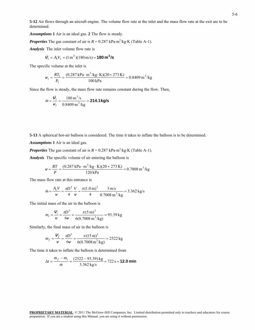
5-12 Air flows through an aircraft engine. The volume flow rate at the inlet and the mass flow rate at the exit are to be determined.
Assumptions 1 Air is an ideal gas. 2 The flow is steady.
Properties The gas constant of air is R = 0.287 kPa⋅m3/kg⋅K (Table A-1).
Analysis The inlet volume flow rate is
/sm 180 3=== m/s) )(180m 1( 2111 VAV&
The specific volume at the inlet is
/kgm 8409.0kPa 100
K) 273K)(20/kgmkPa 287.0( 33
1
11 =
+⋅⋅==
PRT
v
Since the flow is steady, the mass flow rate remains constant during the flow. Then,
kg/s 214.1===/kgm 8409.0
/sm 1803
3
1
1
v
V&&m
5-13 A spherical hot-air balloon is considered. The time it takes to inflate the balloon is to be determined.
Assumptions 1 Air is an ideal gas.
Properties The gas constant of air is R = 0.287 kPa⋅m3/kg⋅K (Table A-1).
Analysis The specific volume of air entering the balloon is
/kgm 7008.0kPa 120
K) 273K)(20/kgmkPa 287.0( 33
=+⋅⋅
==P
RTv
The mass flow rate at this entrance is
kg/s 362.3/kgm 0.7008
m/s 34
m) 0.1(4 3
22====
ππvvVDVA
m c&
The initial mass of the air in the balloon is
kg 39.93/kg)m 6(0.7008
m) 5(6 3
33====
ππvv
V Dm ii
Similarly, the final mass of air in the balloon is
kg 2522/kg)m 6(0.7008
m) 15(6 3
33====
ππvv
V Dm ff
The time it takes to inflate the balloon is determined from
min 12.0==−
=−
=∆ s 722kg/s 362.3
kg )39.932522(m
mmt if
&
PROPRIETARY MATERIALpreparation. If you are a student using this Manual, you are using it without permission.
. © 2011 The McGraw-Hill Companies, Inc. Limited distribution permitted only to teachers and educators for course
5-7
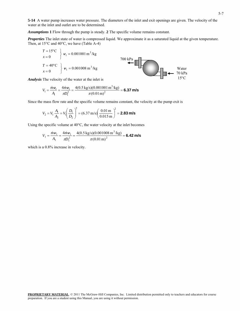
5-14 A water pump increases water pressure. The diameters of the inlet and exit openings are given. The velocity of the water at the inlet and outlet are to be determined.
Assumptions 1 Flow through the pump is steady. 2 The specific volume remains constant.
Properties The inlet state of water is compressed liquid. We approximate it as a saturated liquid at the given temperature. Then, at 15°C and 40°C, we have (Table A-4)
/kgm 001001.0 0
C15 31 =
⎭⎬⎫
=°=
v xT
700 kPa
/kgm 001008.0 0
C40 31 =
⎭⎬⎫
=°=
v xT
Water 70 kPa 15°C Analysis The velocity of the water at the inlet is
PROPRIETARY MATERIAL. © 2011 The McGraw-Hill Companies, Inc. Limited distribution permitted only to teachers and educators for course
m/s 6.37==== 2211
1 m) 01.0(ππDAV
311 /kg)m 1001kg/s)(0.00 5.0(44mm vv &&
ass flow rate and the specific volume remains constant, the velocity at the pump exit is Since the m
m/s 2.83=⎟⎠
⎜⎝
=⎟⎠
⎜⎝
==2
12
12 m 0.015m/s) (6.37
DV
AVV ⎞⎛⎟
⎞⎜⎛ 22
11 m 0.01DA
sing the ecific volume at 40°C, the water velocity at the inlet becomes U sp
m/s 6.42====2
3
21
1
1
11
m) 01.0(/kg)m 1008kg 5.0(44mm vv &&
/s)(0.00ππDA
V
which is a 0.8% increase in velocity.
preparation. If you are a student using this Manual, you are using it without permission.
5-8
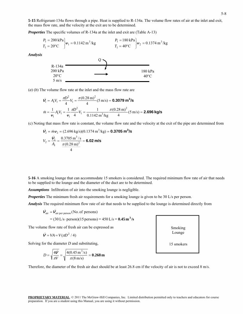
5-15 Refrigerant-134a flows through a pipe. Heat is supplied to R-134a. The volume flow rates of air at the inlet and exit, the mass flow rate, and the velocity at the exit are to be determined.
Properties The specific volumes of R-134a at the inlet and exit are (Table A-13)
PROPRIETARY MATERIAL. © 2011 The McGraw-Hill Companies, Inc. Limited distribution permitted only to teachers and educators for course
=⎭⎬⎫
°==
vTP
/kgm 1142.0C20kPa 200 3
11
1 =⎭⎬⎫
°==
vTP
1 /kgm 1374.0C40kPa 180 3
21
Analysis
(a) (b) The volume flow rate at the inlet and the mass flow rate are
kg/s 2.696
/sm 0.3079 3
====
====
m/s) 5(4
m) 28.0(/kgm 1142.0
14
11
m/s) 5(4
m) 28.0(4
2
31
2
11
1
2
1
2
11
ππ
ππ
VDVAm
VDVA
c
c
vv
V
&
&
(c) Noting that mass flow rate is constant, the volume flow rate and the velocity at the exit of the pipe are determined from
m/s 6.02
/sm 0.3705 3
===
===
4m) 28.0(
s/m 3705.0
/kg)m 74kg/s)(0.13 696.2(
2
32
2
322
&
πcAV
m
V
vV&
&
te of air that needs
Assumptions Infiltration of air into the smoking lounge is negligible.
Properties The minimum fresh air requirements for a smoking lounge is given to be
Analysis The required minimum flow rate of air that needs to be supplied to the from
persons)of No.(rsonair per per =VV
The volume flow rate of fresh air can be expressed as
5-16 A smoking lounge that can accommodate 15 smokers is considered. The required minimum flow rato be supplied to the lounge and the diameter of the duct are to be determined.
30 L/s per person.
lounge is determined directly
/sm 0.45 3=L/s 450= persons)person)(15L/s (30= ⋅
ai&&
)4/( 2DVVA π==V&
Solving for the diameter D and substituting,
m 0.268===m/s) (8
)/sm 45.0(44 3
ππVD V&
Therefore, the diameter of the fresh air duct should be at least 26.8 cm if the velocity of air is not to exceed 8 m/s.
R-134a 200 kPa
20°C 5 m/s
Q
180 kPa40°C
Smoking Lounge
15 smokers
preparation. If you are a student using this Manual, you are using it without permission.
5-9
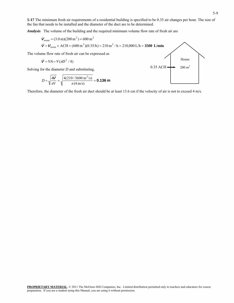
5-17 The minimum fresh air requirements of a residential building is specified to be 0.35 air changes per hour. The size of the fan that needs to be installed and the diameter of the duct are to be determined.
Analysis The volume of the building and the required minimum volume flow rate of fresh air are
PROPRIETARY MATERIAL. © 2011 The McGraw-Hill Companies, Inc. Limited distribution permitted only to teachers and educators for course
==
L/h ,000210h/
m 600)m m)(200 0.3(3
32omV
The volume flow rate of fresh ir can be expressed as
Solving for the diameter D and substituting,
==×= m 210)/h35.0)(m 600(ACH 3
roomVV& L/min 3500==ro
a
)4/( 2DVVA π==V&
m 0.136===m/s) (4
)/sm 3600/210(44 3&
ππVD V
Therefore, the diameter of the fresh air duct should be at least 13.6 cm if the velocity of air is not to exceed 4 m/s.
0.35 ACH
House
200 m2
preparation. If you are a student using this Manual, you are using it without permission.
5-10
Flow Work and Energy Transfer by Mass
5-18C Energy can be transferred to or from a control volume as heat, various forms of work, and by mass.
5-19C Flow energy or flow work is the energy needed to push a fluid into or out of a control volume. Fluids at rest do not possess any flow energy.
5-20C Flowing fluids possess flow energy in addition to the forms of energy a fluid at rest possesses. The total energy of a fluid at rest consists of internal, kinetic, and potential energies. The total energy of a flowing fluid consists of internal, kinetic, potential, and flow energies.
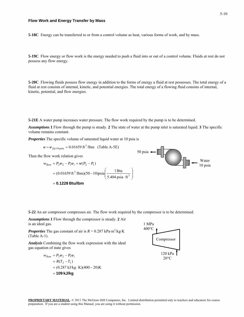
5-21E A water pump increases water pressure. The flow work required by the pump is to be determined.
Assumptions 1 Flow through the pump is steady. 2 The state of water at the pump inlet is saturated liquid. 3 The specific volume remains constant.
Properties The specific volume of saturated liquid water at 10 psia is
/lbmft 01659.0 3psia 10 @ == fv v (Table A-5E)
PROPRIETARY MATERIAL. © 2011 The McGraw-Hill Companies, Inc. Limited distribution permitted only to teachers and educators for course
Then the flow work relation gives
Btu/lbm 0.1228=
⎟⎟⎠
⎞⎜⎜⎝
⎛
⋅−=
−=−=
33
121122flow
ftpsia 5.404Btu 110)psia/lbm)(50ft 01659.0(
)( PPPPw vvv
ed by the compressor is to be determined.
Properties The gas constant of air is R = 0.287 kPa⋅m3/kg⋅K (Table A-1).
nalysis Combining the flow work expression with the ideal gas equation of state gives
50 psia
Water 10 psia
5-22 An air compressor compresses air. The flow work requir
Assumptions 1 Flow through the compressor is steady. 2 Air is an ideal gas.
Compressor
1 MPa 400°C
120 kPa 20°C
A
kJ/kg 109=−⋅=
−=−=
)K20K)(400kJ/kg 287.0()( 12
1122flow
TTRPPw vv
preparation. If you are a student using this Manual, you are using it without permission.
5-11
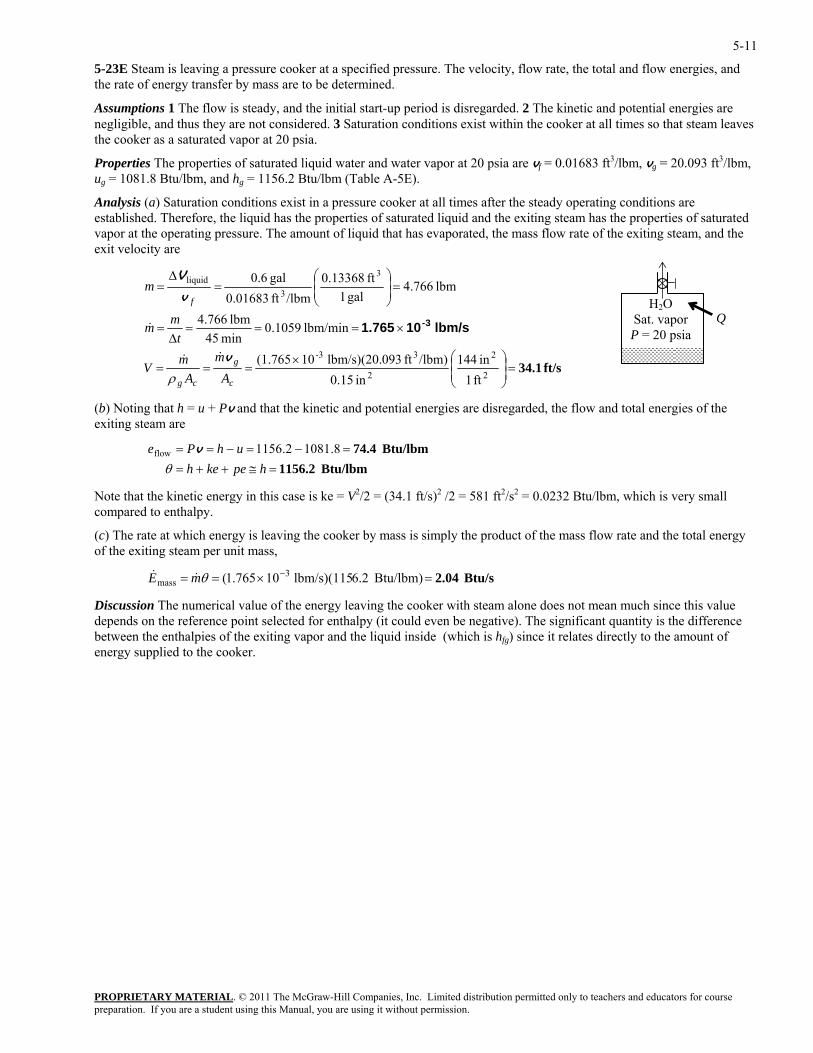
5-23E Steam is leaving a pressure cooker at a specified pressure. The velocity, flow rate, the total and flow energies, and the rate of energy transfer by mass are to be determined.
Assumptions 1 The flow is steady, and the initial start-up period is disregarded. 2 The kinetic and potential energies are negligible, and thus they are not considered. 3 Saturation conditions exist within the cooker at all times so that steam leaves the cooker as a saturated vapor at 20 psia.
Properties The properties of saturated liquid water and water vapor at 20 psia are vf = 0.01683 ft3/lbm, vg = 20.093 ft3/lbm, ug = 1081.8 Btu/lbm, and hg = 1156.2 Btu/lbm (Table A-5E).
Analysis (a) Saturation conditions exist in a pressure cooker at all times after the steady operating conditions are established. Therefore, the liquid has the properties of saturated liquid and the exiting steam has the properties of saturated vapor at the operating pressure. The amount of liquid that has evaporated, the mass flow rate of the exiting steam, and the exit velocity are
PROPRIETARY MATERIAL. © 2011 The McGraw-Hill Companies, Inc. Limited distribution permitted only to teachers and educators for course
ft/s 34.1=⎟⎠
⎜⎝
22 ft 1in 0.15ccg AAρ
(b) Noting that h = u + P
⎟⎞
⎜⎛×
===
×===∆
=
⎞⎛∆
233-
3liquid
in 144/lbm)ft 093lbm/s)(20. 10(1.765
lbm/min 1059.0min 45
lbm 766.4
ft 13368.0gal 0.6
gmmV
tm
v
V
&&
& lbm/s 101.765 3-
v and that the kinetic and potential energies are disregarded, the flow and total energies of the
hpekehθ8.1081w
leaving the cooker by mass is simply the product of the mass flow rate and the total energy f the exiting steam per unit mass,
Discussion The numerical value of the energy leaving the cooker with steam alone does not mean much since this value depends on the reference point selected for enthalpy (it could even be negative). The significant quantity is the difference between the enthalpies of the exiting vapor and the liquid inside (which is hfg) since it relates directly to the amount of energy supplied to the cooker.
H2O Sat. vapor P = 20 psia
Q
=⎟⎟⎠
⎜⎜⎝
== 3 lbm 766.4gal 1/lbmft 0.01683f
m
mv
exiting steam are
=−== uhPe 2.1156v
Btu/lbm 1156.2Btu/lbm 74.4
=≅++==−
flo
Note that the kinetic energy in this case is ke = V2/2 = (34.1 ft/s)2 /2 = 581 ft2/s2 = 0.0232 Btu/lbm, which is very small compared to enthalpy.
(c) The rate at which energy is o
Btu/s 2.04=×== − Btu/lbm) 6.2lbm/s)(115 10765.1( 3mass θmE &&
preparation. If you are a student using this Manual, you are using it without permission.
5-12
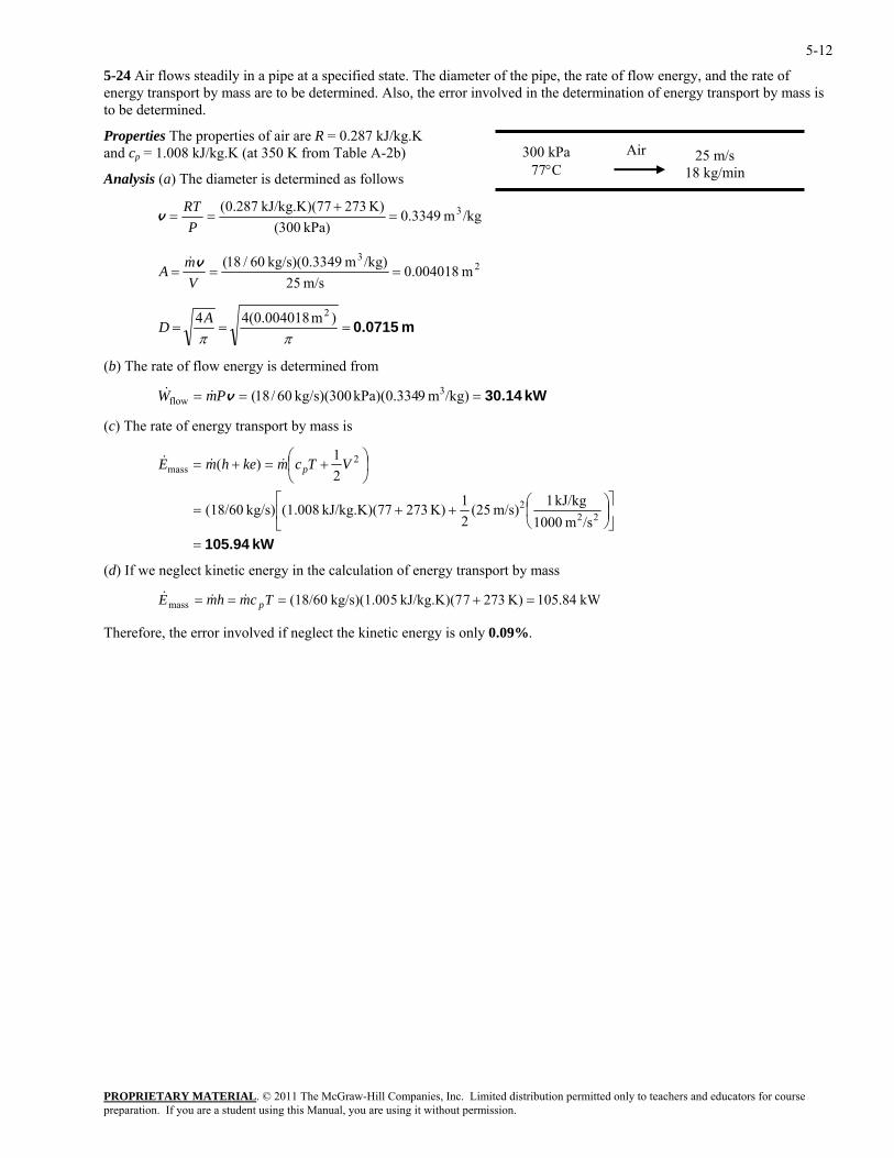
5-24 Air flows steadily in a pipe at a specified state. The diameter of the pipe, the rate of flow energy, and the rate of energy transport by mass are to be determined. Also, the error involved in the determination of energy transport by mass is to be determined.
PROPRIETARY MATERIAL. © 2011 The McGraw-Hill Companies, Inc. Limited distribution permitted only to teachers and educators for course
Properties The properties of air are R = 0.287 kJ/kg.K and cp = 1.008 kJ/kg.K (at 350 K from Table A-2b)
Analysis (a) The diameter is determined as follows
/kgm 3349.0kPa) 300(
K) 2737kJ/kg.K)(7 287.0( 3=+
==P
RTv
300 kPa 77°C
Air 25 m/s 18 kg/min
23
m 004018.0m/s 25
/kg)m 49kg/s)(0.33 60/18(===
VmA v&
m 0.0715===ππ
D )m (0.00401844 2A
) The rate of flow energy is determined from
/kg)m 9Pa)(0.334 3
(c) The rate of energy transport by mass is
(b
== k kg/s)(300 60/18(flow vPmW && kW 30.14=
kW 105.94=⎣ ⎝ 1000 ⎥
⎦
⎤⎢⎡
⎟⎠⎞
⎜⎛++=
⎟⎠⎞
⎜⎝⎛ +=+=
222
2mass
/smkJ/kg 1m/s) (25
21K) 2737kJ/kg.K)(7 (1.008kg/s) (18/60
21)( VTcmkehmE p&&&
(d) If we neglect kinetic energy in the calculation of energy transport by mass
mass p
Therefore, the error involved if neglect the kinetic energy is only 0.09%.
K) 2737kJ/kg.K)(7 5kg/s)(1.00 (18/60 =+=== TcmhmE &&& kW 105.84
preparation. If you are a student using this Manual, you are using it without permission.
5-13
Steady Flow Energy Balance: Nozzles and Diffusers
5-25C No.
5-26C It is mostly converted to internal energy as shown by a rise in the fluid temperature.
5-27C The kinetic energy of a fluid increases at the expense of the internal energy as evidenced by a decrease in the fluid temperature.
5-28C Heat transfer to the fluid as it flows through a nozzle is desirable since it will probably increase the kinetic energy of the fluid. Heat transfer from the fluid will decrease the exit velocity.
PROPRIETARY MATERIALpreparation. If you are a student using this Manual, you are using it without permission.
. © 2011 The McGraw-Hill Companies, Inc. Limited distribution permitted only to teachers and educators for course
5-14
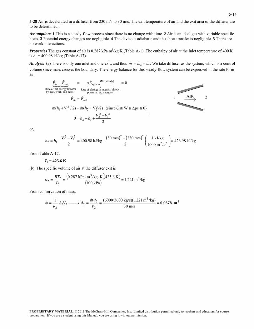
5-29 Air is decelerated in a diffuser from 230 m/s to 30 m/s. The exit temperature of air and the exit area of the diffuser are to be determined.
Assumptions 1 This is a steady-flow process since there is no change with time. 2 Air is an ideal gas with variable specific heats. 3 Potential energy changes are negligible. 4 The device is adiabatic and thus heat transfer is negligible. 5 There are no work interactions.
Properties The gas constant of air is 0.287 kPa.m3/kg.K (Table A-1). The enthalpy of air at the inlet temperature of 400 K is h1 = 400.98 kJ/kg (Table A-17).
PROPRIETARY MATERIAL. © 2011 The McGraw-Hill Companies, Inc. Limited distribution permitted only to teachers and educators for course
&Analysis (a) There is only one inlet and one exit, and thus & &m m m1 2= = . We take diffuser as the system, which is a control volume since mass crosses the boundary. The energy balance for this steady-flow system can be expressed in the rate form as
outin
energies etc. potential, kinetic, internal,in change of Rate
(steady) 0system
mass and work,heat,by nsferenergy tranet of Rate
outin 0
EE
EEE
&&
44 344 21&
43421&&
=
=∆=−
AIR 1 2
20
0)peW (since /2)V+()2/(2
12
212
222
211
VVhh
QhmVhm
−+−=
≅∆≅≅=+ &&&&
,
or,
(
) ( )kJ/kg 426.98
/sm 1000kJ/kg 1
2m/s 230
22
222=⎟
⎟⎠
⎞⎜⎜⎝
⎛−
rom Table A-17,
b) The specific volume of air at the diffuser exit is
m/s 30kJ/kg 400.98
212
12 −=−
−=VV
hh2
F
T2 = 425.6 K
(
( )( )( ) /kgm 1.221
kPa 100K 425.6K/kgmkPa 0.287 3
3
2
22 =
⋅⋅==
PRT
v
From conservation of mass,
2m 0.0678===⎯→⎯=m/s 30
)/kgm 1.221)(kg/s 36006000(1 3
2
2222
2 Vm
AVAmv
v
&&
preparation. If you are a student using this Manual, you are using it without permission.
5-15
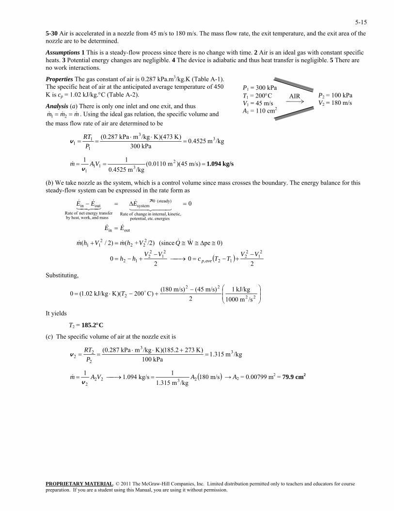
5-30 Air is accelerated in a nozzle from 45 m/s to 180 m/s. The mass flow rate, the exit temperature, and the exit area of the nozzle are to be determined.
Assumptions 1 This is a steady-flow process since there is no change with time. 2 Air is an ideal gas with constant specific heats. 3 Potential energy changes are negligible. 4 The device is adiabatic and thus heat transfer is negligible. 5 There are no work interactions.
PROPRIETARY MATERIAL. © 2011 The McGraw-Hill Companies, Inc. Limited distribution permitted only to teachers and educators for course
&
P1 = 300 kT
Pa 200°C 1 =
V1 = 45 m/s A1 = 110 cm2
P2 = 100 kPa V2 = 180 m/s
AIR
Properties The gas constant of air is 0.287 kPa.m3/kg.K (Table A-1). The specific heat of air at the anticipated average temperature of 450 K is cp = 1.02 kJ/kg.°C (Table A-2).
Analysis (a) There is only one inlet and one exit, and thus . Using the ideal gas relation, the specific volume and
the mass flow rate of air are determined to be & &m m m1 2= =
/kgm 0.4525kPa 300
)K 473)(K/kgmkPa 0.287( 33
1
11 =
⋅⋅==
PRT
v
kg/s 1.094=== )m/s 45)(m 0.0110(/kgm 0.4525 311
1VAm
v&
b
11 2
stem, which is a control volume since mass crosses the boundary. The energy balance for this stem can be expressed in the rate form as
fRoutin 0
EE
EEE
&&
44 344 21&
43421&&
=
=∆=−
( ) We take nozzle as the systeady-flow sy
outin
energies etc. potential, kinetic, internal,in change of Rate
(steady) 0system
mass and work,heat,by nsferenergy tranet o ate
( )2
02
0
0)peW (since /2)+()2/(2
12
212,
21
22
12
222
211
VVTTc
VVhh
QVhmVhm
avep−
+−=⎯→⎯−
+−=
≅∆≅≅=+ &&&&
Substituting,
⎟⎟⎠
⎞⎜⎜⎝
⎛−+−⋅=
22
22
2/sm 1000
kJ/kg 12
)m/s 45()m/s 180()C200)(KkJ/kg 1.02(0 oT
It yields
T2 = 185.2°C
(c) The specific volume of air at the nozzle exit is
/kgm 1.315kPa 100
)K 273185.2)(K/kgmkPa 0.287( 33
2
22 =
+⋅⋅==
PRT
v
( )m/s 180/kgm 1.315
1kg/s .094112322
2AVAm =⎯→⎯=
v& → A2 = 0.00799 m2 = 79.9 cm2
preparation. If you are a student using this Manual, you are using it without permission.
5-16
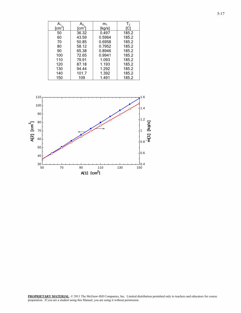
5-31 Problem 5-30 is reconsidered. The effect of the inlet area on the mass flow rate, exit velocity, and the exit area as the inlet area varies from 50 cm2 to 150 cm2 is to be investigated, and the final results are to be plotted against the inlet area.
Analysis The problem is solved using EES, and the solution is given below.
Function HCal(WorkFluid$, Tx, Px) "Function to calculate the enthalpy of an ideal gas or real gas" If 'Air' = WorkFluid$ then HCal:=ENTHALPY(Air,T=Tx) "Ideal gas equ." else HCal:=ENTHALPY(WorkFluid$,T=Tx, P=Px)"Real gas equ." endif end HCal "System: control volume for the nozzle" "Property relation: Air is an ideal gas" "Process: Steady state, steady flow, adiabatic, no work" "Knowns - obtain from the input diagram" WorkFluid$ = 'Air' T[1] = 200 [C] P[1] = 300 [kPa] Vel[1] = 45 [m/s] P[2] = 100 [kPa] Vel[2] = 180 [m/s] A[1]=110 [cm^2] Am[1]=A[1]*convert(cm^2,m^2) "Property Data - since the Enthalpy function has different parameters for ideal gas and real fluids, a function was used to determine h." h[1]=HCal(WorkFluid$,T[1],P[1]) h[2]=HCal(WorkFluid$,T[2],P[2]) "The Volume function has the same form for an ideal gas as for a real fluid." v[1]=volume(workFluid$,T=T[1],p=P[1]) v[2]=volume(WorkFluid$,T=T[2],p=P[2]) "Conservation of mass: " m_dot[1]= m_dot[2] "Mass flow rate" m_dot[1]=Am[1]*Vel[1]/v[1] m_dot[2]= Am[2]*Vel[2]/v[2] "Conservation of Energy - SSSF energy balance" h[1]+Vel[1]^2/(2*1000) = h[2]+Vel[2]^2/(2*1000) "Definition" A_ratio=A[1]/A[2] A[2]=Am[2]*convert(m^2,cm^2)
PROPRIETARY MATERIALpreparation. If you are a student using this Manual, you are using it without permission.
. © 2011 The McGraw-Hill Companies, Inc. Limited distribution permitted only to teachers and educators for course
5-17
A1 [cm2]
A2 [cm2]
m1 [kg/s]
T2 [C]
50 60 70 80 90
100 110 120 130 140 150
36.32 43.59 50.85 58.12 65.38 72.65 79.91 87.18 94.44 101.7 109
0.497 0.5964 0.6958 0.7952 0.8946 0.9941 1.093 1.193 1.292 1.392 1.491
185.2 185.2 185.2 185.2 185.2 185.2 185.2 185.2 185.2 185.2 185.2
50 70 90 110 130 15030
40
50
60
70
80
90
100
110
0.4
0.6
0.8
1
1.2
1.4
1.6
A[1] [cm2]
A[2
] [c
m2 ]
m[1
] [k
g/s]
PROPRIETARY MATERIALpreparation. If you are a student using this Manual, you are using it without permission.
. © 2011 The McGraw-Hill Companies, Inc. Limited distribution permitted only to teachers and educators for course
5-18
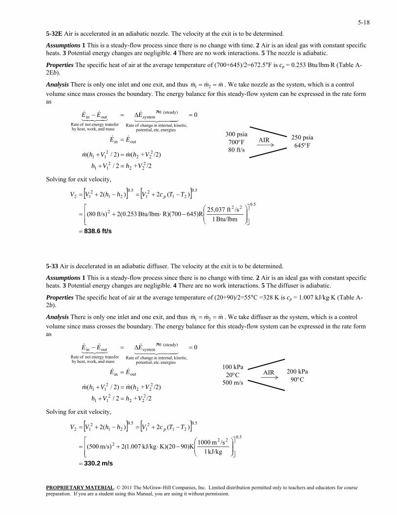
5-32E Air is accelerated in an adiabatic nozzle. The velocity at the exit is to be determined.
Assumptions 1 This is a steady-flow process since there is no change with time. 2 Air is an ideal gas with constant specific heats. 3 Potential energy changes are negligible. 4 There are no work interactions. 5 The nozzle is adiabatic.
Properties The specific heat of air at the average temperature of (700+645)/2=672.5°F is cp = 0.253 Btu/lbm⋅R (Table A-2Eb).
Analysis There is only one inlet and one exit, and thus mmm &&& == 21 . We take nozzle as the system, which is a control volume since mass crosses the boundary. The energy balance for this steady-flow system can be expressed in the rate form as
rgies etc. potential,
kinetic, internal,in change of Rate
(steady) 0system
mass and work,t,nsferenergy tranet of Rate
outin 0
EE
EEE
&&
444 344 21&
43421&&
=
=∆=−
2
222
11
222
VhVh
Vhm
=+
= &
,
PROPRIETARY MATERIAL. © 2011 The McGraw-Hill Companies, Inc. Limited distribution permitted only to teachers and educators for course
outin
eneheaby
/2+2/
/2)+()2
300 psia 700°F 80 ft/s
AIR 250 psia 645°F
/( 211 Vhm +&
Solving for exit velocity
[ ] [ ]−+=−+= 212
1212
12 )(2)(2 TTcVhhVV p
⎥⎥⎦
⎤
⎢⎢⎣
⎡⎟⎟⎠
⎞⎜⎜⎝
⎛−⋅+=
5.022
2
Btu/lbm 1/sft 25,037
645)RR)(700Btu/lbm 253.0(2ft/s) 80(
ft/s 838.6=
5.05.0
3 Air is decelerated in an adiabatic diffuser. The velocity at the exit is to be determined.
ssumptio s 1 This is a steady-flow process since there is no change with time. 2 Air is an ideal gas with constant specific heats. 3 Potential energy changes are negligible. 4 There are no work interactions. 5 The diffuser is adiabatic.
Properti e specific heat of air at the average temperature of (20+90)/2=55°C =328 K is kg⋅K (Table A-2b).
inlet and one exit, and thus
5-3
A n
es Th cp = 1.007 kJ/
Analysis There is only one mmm &&& == 21 . We take diffuser as the system, which is a control olume since mass crosses the boundary. The energy balance for this steady-flow system can be expressed in the rate form
as
Solving for exit velocity,
v
outin
energies etc. potential, kinetic, internal,in change of Rate
(steady) 0system
mass and work,heat,by nsferenergy tranet of Rate
outin 0
EE
EEE
&&
444 344 21&
43421&&
=
=∆=−
AIR 100 kPa
20°C 500 m/s
200 kPa 90°C
/2+2/
/2)+()2/(2
222
11
222
211
VhVh
VhmVhm
=+
=+ &&
[ ] [ ]
m/s 330.2=
⎥⎥⎦
⎤
⎢⎢⎣
⎡⎟⎟⎠
⎞⎜⎜⎝
⎛−⋅+=
−+=−+=5.022
2
5.021
21
5.021
212
kJ/kg 1/sm 1000)K90K)(20kJ/kg 007.1(2m/s) 500(
)(2)(2 TTcVhhVV p
preparation. If you are a student using this Manual, you are using it without permission.
5-19
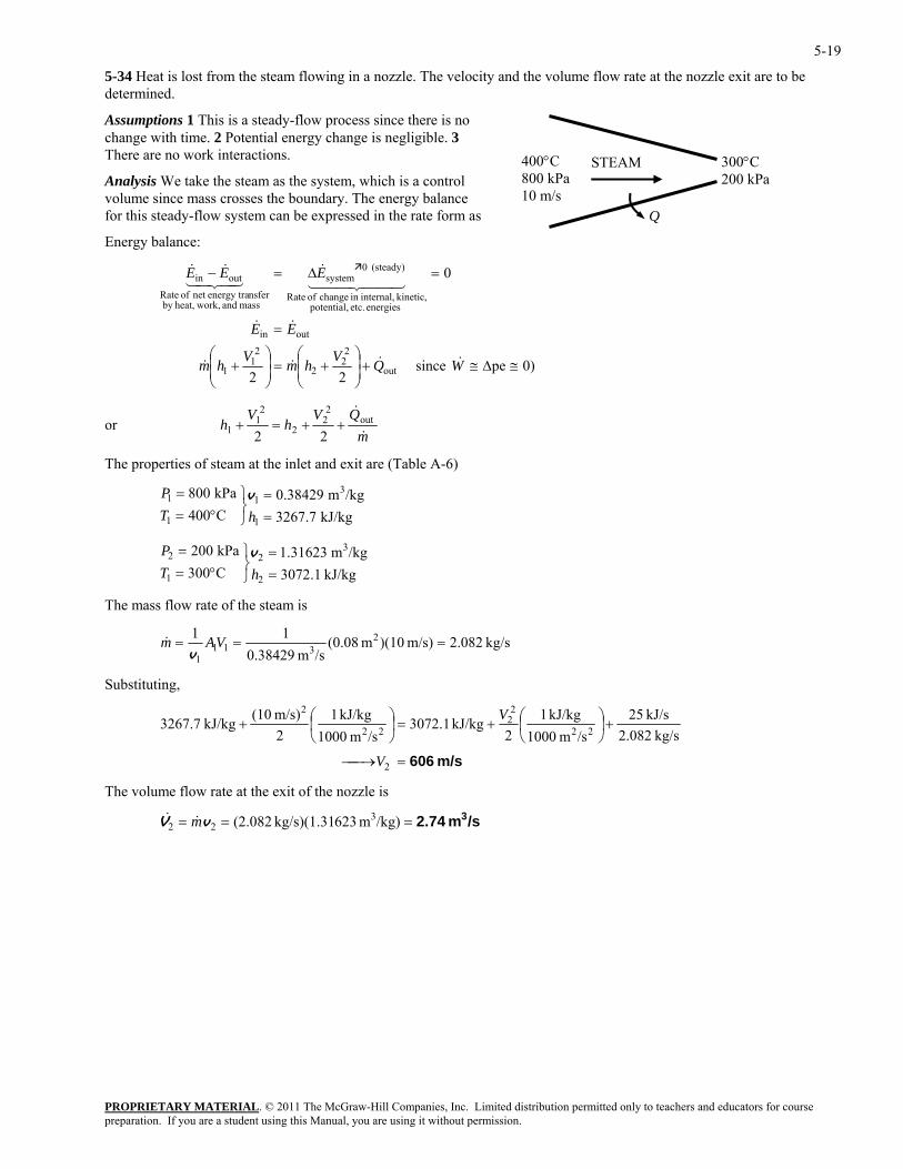
5-34 Heat is lost from the steam flowing in a nozzle. The velocity and the volume flow rate at the nozzle exit are to be determined.
400°C 800 kPa 10 m/s
STEAM
Q
300°C 200 kPa
Assumptions 1 This is a steady-flow process since there is no change with time. 2 Potential energy change is negligible. 3 There are no work interactions.
Analysis We take the steam as the system, which is a control volume since mass crosses the boundary. The energy balance for this steady-flow system can be expressed in the rate form as
Energy balance:
0)pe since 22
0
out
22
2
21
1
outin
energies etc. potential, kinetic, internal,in change of Rate
(steady) 0system
mass and work,heat,by nsferenergy tranet of Rate
outin
≅∆≅+⎟⎟⎠
⎞⎜⎜⎝
⎛+=⎟
⎟⎠
⎞⎜⎜⎝
⎛+
=
=∆=−
WQVhmVhm
EE
EEE
&&&&
&&
44 344 21&
43421&&
PROPRIETARY MATERIAL. © 2011 The McGraw-Hill Companies, Inc. Limited distribution permitted only to teachers and educators for course
or m
hh&21 22
++=+ QVV &
out2
22
1
at the inlet and exit are (Table A-6)
1
==
⎭⎬⎫
°==
hTP v
3C300 2
3
1 =⎭⎬°= hT
The mass flow rate of the steam is
The properties of steam
kJ/kg 7.3267/kgm 38429.0
C400kPa 008
1
31
1
kJ/kg 1.3072/kgm 3162.1kPa 020 22 =⎫=P v
kg/s 2.082m/s) )(10m (0.08/sm 0.38429
11 2311
1== =& VAm
v
Substituting,
m/s 606=⎯→⎯
+⎟⎠⎞
⎜⎝⎛+=⎟
⎠⎞
⎜⎝⎛+
2
22
22
22
2
kg/s 2.082kJ/s 25
/sm 1000kJ/kg 1
2kJ/kg 1.3072
/sm 1000kJ/kg 1
2m/s) (10kJ/kg 3267.7
V
V
The volume flow rate at the exit of the nozzle is
/sm 2.74 3=== /kg)m 623kg/s)(1.31 (2.082 322 vV m&&
preparation. If you are a student using this Manual, you are using it without permission.
5-20
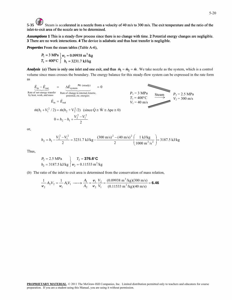
5-35 Steam is accelerated in a nozzle fromelerated in a nozzle from a velocity of 40 m/s to 300 m/s. The exit temperature and the ratio of the
rgy changes are negligible. is adiabatic and thus heat transfer is negligible.
Properties From the steam tables (Table A-6),
MPa 3 311 =
⎬⎫=P v
a velocity of 40 m/s to 300 m/s. The exit temperature and the ratio of the
rgy changes are negligible. is adiabatic and thus heat transfer is negligible.
Properties From the steam tables (Table A-6),
/kgm 0.09938MPa 3 311 =
⎬⎫=P v
inlet-to-exit area of the nozzle are to be determined.
Assumptions 1 This is a steady-flow process since there is no change with time. 2 Potential ene
inlet-to-exit area of the nozzle are to be determined.
Assumptions 1 This is a steady-flow process since there is no change with time. 2 Potential ene3 There are no work interactions. 4 The device 3 There are no work interactions. 4 The device
/kgm 0.09938kJ/kg 3231.7C400 11 =⎭°= hT
Analysis (a) There is only one inlet and one exit, and thus & & &m m m1 2
kJ/kg 3231.7C400 11 =⎭°= hT
Analysis (a) There is only one inlet and one exit, and thus & & &m m m1 2= = . We take nozzle as the system, which is a control volume since mass crosses the boundary. The energy balance for this steady-flow system can be expressed in the rate form as
ork,atnsferenergy tranet of Rate
outin 0
EE
EEE
&&
44 344 21&
43421&&
=
=∆=−
Steam P2 = 2.5 MPaV2 = 300 m/s
P1 = 3 MPa T1 = 400°C V1 = 40 m/s outin
energies etc. potential, kinetic, internal,in change of Rate
(steady) 0system
mass and whe ,by
20
0)peW (since /2)V+()2/(2
12
212
222
211
VVhh
QhmVhm
−+−=
≅∆≅≅=+ &&&&
or,
kJ/kg 3187/sm 1000
kJ/kg 12
)m/s 04()m/s 300(kJ/kg 3231.7
2 2212
12 =⎟⎟
⎜⎜−
−=−
−=VV
hh .52222
⎠
⎞
⎝
⎛
hus,
(b) The ratio of the inlet to exit area is determined from the conservation of mass relation,
T
/kgm 0.11533kJ/kg 3187.5MPa 2.5
32
2
2
2
=°=
⎭⎬⎫
==
v
C376.6ThP
6.46===⎯→⎯=)m/s 40)(/kgm 0.11533()m/s 300)(/kgm 0.09938(11
3
3
1
2
2
1
2
111
122
2 VV
AA
VAVAv
v
vv
PROPRIETARY MATERIALpreparation. If you are a student using this Manual, you are using it without permission.
. © 2011 The McGraw-Hill Companies, Inc. Limited distribution permitted only to teachers and educators for course
5-21
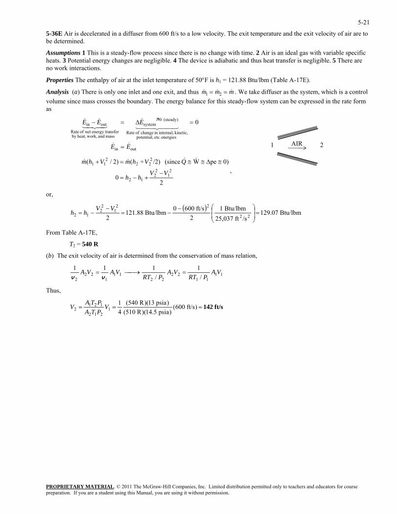
5-36E Air is decelerated in a diffuser from 600 ft/s to a low velocity. The exit temperature and the exit velocity of air are to be determined.
Assumptions 1 This is a steady-flow process since there is no change with time. 2 Air is an ideal gas with variable specific heats. 3 Potential energy changes are negligible. 4 The device is adiabatic and thus heat transfer is negligible. 5 There are no work interactions.
Properties The enthalpy of air at the inlet temperature of 50°F is h1 = 121.88 Btu/lbm (Table A-17E).
PROPRIETARY MATERIAL. © 2011 The McGraw-Hill Companies, Inc. Limited distribution permitted only to teachers and educators for course
mAnalysis (a) There is only one inlet and one exit, and thus & &m m1 2& = = . We take diffuser as the system, which is a contrvolume since mass crosses the boundary. The energy balance for this steady-flow system can be expressed in the rate f
ol orm
as
outin
energies etc. potential, kinetic, internal,in change of Rate
(steady) 0system
mass and work,heat,by nsferenergy tranet of Rate
outin 0
EE
EEE
&&
44 344 21&
43421&&
=
=∆=−
AIR 1 2
20
0)peW (since /2)+()2/(2
12
212
222
211
VVhh
QVhmVhm
−+−=
≅∆≅≅=+ &&&&
,
or,
( )Btu/lbm 129.07
/sft 25,03722 ⎠⎝
Btu/lbm 1ft/s 6000Btu/lbm 121.88
22
221
2=⎟
⎟⎞
⎜⎜⎛−
−=−V
rom Tabl A-17E,
T2 = 540 R
(b) The exit velocity of air is determined from the conservation of mass relation,
212 −=
Vhh
F e
1111
2222
111
222 /
1/
111 VAPRT
VAPRT
VAVA =⎯→⎯=vv
Thus,
ft/s 142=== )ft/s 600()psia 14.5)(R 051(
)psia 13)(R 540(41
1212
1212 V
PTAPTA
V
preparation. If you are a student using this Manual, you are using it without permission.
5-22
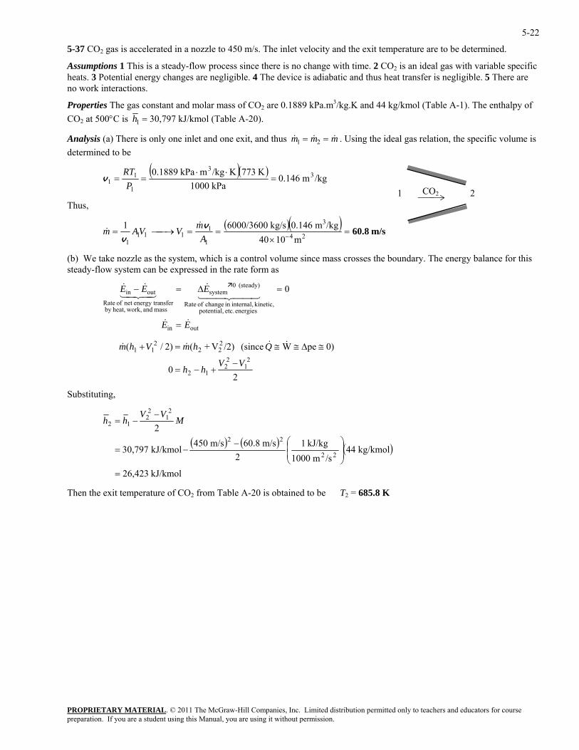
5-37 CO2 gas is accelerated in a nozzle to 450 m/s. The inlet velocity and the exit temperature are to be determined.
Assumptions 1 This is a steady-flow process since there is no change with time. 2 CO2 is an ideal gas with variable specific heats. 3 Potential energy changes are negligible. 4 The device is adiabatic and thus heat transfer is negligible. 5 There are no work interactions.
Properties The gas constant and molar mass of CO2 are 0.1889 kPa.m3/kg.K and 44 kg/kmol (Table A-1). The enthalpy of CO2 at 500°C is h1 = 30,797 kJ/kmol (Table A-20).
Analysis (a) There is only one inlet and one exit, and thus & & &m m m1 2= = . Using the ideal gas relation, the specific volume is determined to be
( )( )/kgm 0.146
kPa 1000K 773K/kgmkPa 0.1889 3
3
1
11 =
⋅⋅==
PRT
v
PROPRIETARY MATERIAL. © 2011 The McGraw-Hill Companies, Inc. Limited distribution permitted only to teachers and educators for course
Thus,
( )( ) m/s60.8 m1040 24
1
1111
1=
×==⎯→⎯= −A
VVAmv
& /kgm 0.146kg/s 6000/36001 3mv&
) We ta e as the system, which is a control volume since mass crosses the boundary. The energy balance for this can be expressed in the rate form as
outin 0
EE
EEE
&&
44 344 21&
43421&&
=
=∆=−
CO21 2
(b ke nozzlsteady-flow system
outin
energies etc. potential, kinetic, internal,in change of Rate
(steady) 0system
mass and work,heat,by nsferenergy tranet of Rate
20
21
22 VV
hh−
+−=
0)peW (since /2)V+()2/(
12
222
211 QhmVhm ≅∆≅≅=+ &&&&
Substituting,
( ) ( ) ( )
kJ/kmol 26,423
kg/kmol 44/sm 1000
kJ/kg 12
m/s 60.8m/s 450kJ/kmol 30,797
2
22
22
21
22
12
=
⎟⎟⎠
⎞⎜⎜⎝
⎛−−=
−−= M
VVhh
Then the exit temperature of CO2 from Table A-20 is obtained to be T2 = 685.8 K
preparation. If you are a student using this Manual, you are using it without permission.
5-23
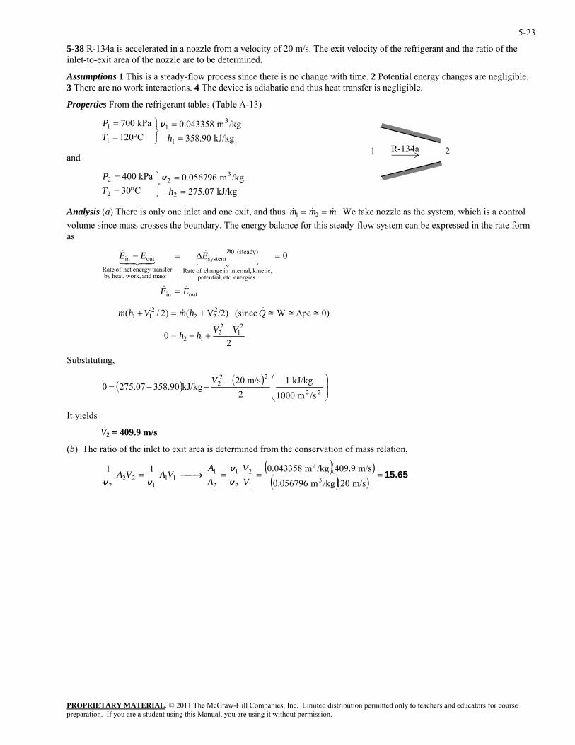
5-38 R-134a is accelerated in a nozzle from a velocity of 20 m/s. The exit velocity of the refrigerant and the ratio of the inlet-to-exit area of the nozzle are to be determined.
Assumptions 1 This is a steady-flow process since there is no change with time. 2 Potential energy changes are negligible. 3 There are no work interactions. 4 The device is adiabatic and thus heat transfer is negligible.
Properties From the refrigerant tables (Table A-13)
kJ/kg 358.90
/kgm 0.043358C120kPa 700
1
31
1
1
==
⎭⎬⎫
°==
hTP v
PROPRIETARY MATERIAL. © 2011 The McGraw-Hill Companies, Inc. Limited distribution permitted only to teachers and educators for course
kPa 004 32 =⎫=P v
R-134a 1 2 and
kJ/kg 275.07C30 22 =⎭
⎬°= hT
Analysis (a) There is only one inlet and one exit, and thus & & &m m m
/kgm 0.0567962
1 2= = . We take nozzle as the system, which is a control voluma
e since mass crosses the boundary. The energy balance for this steady-flow system can be expressed in the rate form s
outin 0
EE
EEE
&&
44 344 21&
43421&&
=
=∆=−
of Rate
outin
energies etc. potential, kinetic, internal,in change of Rate
(steady) 0system
mass and work,heat,by nsferenergy tranet
20
0)peW (since /2)V+()2/(2
12
212
222
211
VVhh
QhmVhm
−+−=
≅∆≅≅=+ &&&&
Substituting,
( ) ( )
/sm 1000kJ/kg 1
2m/s 20
kJ/kg358.90275.07022
222
⎟⎟⎠
⎞⎜⎜⎝
⎛−+−=
V
It yields
V2 = 409.9 m/s
(b) The ratio of the inlet to exit area is determined from the conservation of mass relation,
( )( )( )( )
15.65===⎯→⎯=m/s 20/kgm 0.056796
m/s 409.9/kgm 0.043358113
3
1
2
2
1
2
111
122
2 VV
AA
VAVAv
v
vv
preparation. If you are a student using this Manual, you are using it without permission.
5-24
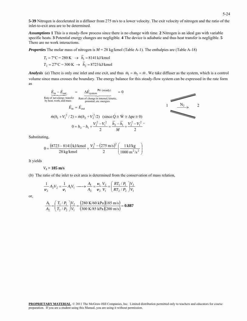
5-39 Nitrogen is decelerated in a diffuser from 275 m/s to a lower velocity. The exit velocity of nitrogen and the ratio of the inlet-to-exit area are to be determined.
Assumptions 1 This is a steady-flow process since there is no change with time. 2 Nitrogen is an ideal gas with variable specific heats. 3 Potential energy changes are negligible. 4 The device is adiabatic and thus heat transfer is negligible. 5 There are no work interactions.
Properties The molar mass of nitrogen is M = 28 kg/kmol (Table A-1). The enthalpies are (Table A-18)
kJ/kmol 8723 K 300=C27 22 =→°= hT
Analysis (a) There is only one inlet and one exit, and thus & & &m m m
kJ/kmol 8141 K 280=C7 1 =→°= hT1
1 2= = . We take diffuser as the system, which is a control voluma
e since mass crosses the boundary. The energy balance for this steady-flow system can be expressed in the rate form s
outin 0
EE
EEE
&&
44 344 21&
43421&&
=
=∆=−
PROPRIETARY MATERIAL. © 2011 The McGraw-Hill Companies, Inc. Limited distribution permitted only to teachers and educators for course
of Rate
outin
energies etc. potential, kinetic, internal,in change of Rate
(steady) 0system
mass and work,heat,by nsferenergy tranet
N21 2
220 2
1V
h +
0)peW (since /2)+()2/(2
12
2122
12
2
222
211
VVM
hhVh
QVhmVhm
−+
−=
−−=
≅∆≅≅=+ &&&&
,
Substituting,
( ) ( )⎟⎟⎠
⎞⎜⎜⎝
⎛−+
−=
22
222
/sm 1000kJ/kg 1
2m/s 275
kg/kmol 28kJ/kmol 814187230
V
It yields
V2 = 185 m/s
(b) The ratio of the inlet to exit area is determined from the conservation of mass relation,
or,
( )( )( )( ) 0.887==⎟⎟
⎠
⎞⎜⎜⎝
⎛=
⎟⎟⎠
⎞⎜⎜⎝
⎛==⎯→⎯=
m/s 200kPa K/85 300m/s 185kPa K/60 280
//
//11
1
2
22
11
2
1
1
2
22
11
1
2
2
1
2
111
122
2
VV
PTPT
AA
VV
PRTPRT
VV
AA
VAVAv
v
vv
preparation. If you are a student using this Manual, you are using it without permission.
5-25
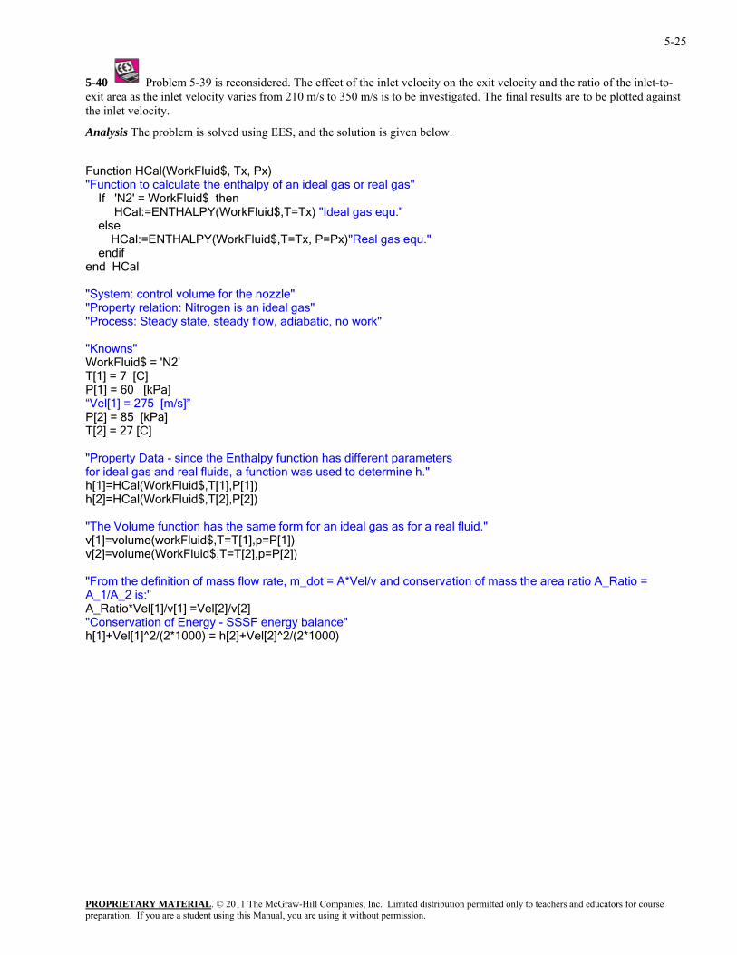
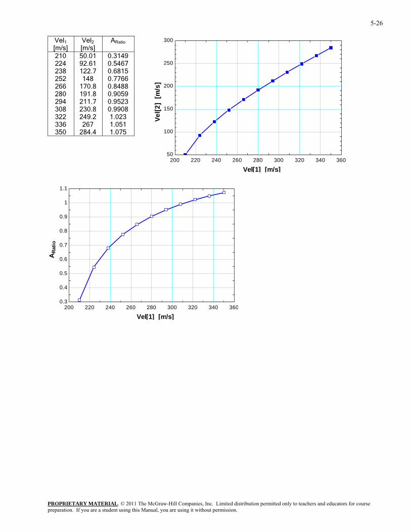
5-40 Problem 5-39 is reconsidered. The effect of the inlet velocity on the exit velocity and the ratio of the inlet-to-exit area as the inlet velocity varies from 210 m/s to 350 m/s is to be investigated. The final results are to be plotted against
nalysis The problem is solved using EES, and the solution is given below.
ENTHALPY(WorkFluid$,T=Tx, P=Px)"Real gas equ."
teady state, steady flow, adiabatic, no work"
'
/s]” a]
ers tion was used to determine h."
for an ideal gas as for a real fluid."
l/v and conservation of mass the area ratio A_Ratio =
[1]+Vel[1]^2/(2*1000) = h[2]+Vel[2]^2/(2*1000)
the inlet velocity.
A
Function HCal(WorkFluid$, Tx"Function to calculate the enth
, Px) alpy of an ideal gas or real gas"
2' = WorkFluid$ then If 'N HCal:=ENTHALPY(WorkFluid$,T=Tx) "Ideal gas equ." else HCal:= endif end HCal "System: control volume for the nozzle" "Property relation: Nitrogen is an ideal gas" "Process: S "Knowns" WorkFluid$ = 'N2T[1] = 7 [C] P[1] = 60 [kPa]
[m
“Vel[1] = 275 P[2] = 85 [kPT[2] = 27 [C] "Property Data - since the Enthalpy function has different parametfor ideal gas and real fluids, a func
[1]=HCal(WorkFluid$,T[1],P[1]) hh[2]=HCal(WorkFluid$,T[2],P[2]) "The Volume function has the same formv[1]=volume(workFluid$,T=T[1],p=P[1]) v[2]=volume(WorkFluid$,T=T[2],p=P[2]) "From the definition of mass flow rate, m_dot = A*VeA_1/A_2 is:" A_Ratio*Vel[1]/v[1] =Vel[2]/v[2] "Conservation of Energy - SSSF energy balance"h
PROPRIETARY MATERIALpreparation. If you are a student using this Manual, you are using it without permission.
. © 2011 The McGraw-Hill Companies, Inc. Limited distribution permitted only to teachers and educators for course
5-26
Vel1 [m/s]
Vel2 [m/s]
ARatio
210 224 238 252 266 280 294 308 322 336 350
50.01 92.61 122.7 148
170.8 191.8 211.7 230.8 249.2 267
284.4
0.3149 0.5467 0.6815 0.7766 0.8488 0.9059 0.9523 0.9908 1.023 1.051 1.075
200 220 240 260 280 300 320 340 36050
100
150
200
250
300
Vel[1] [m/s]
Vel[2
] [m
/s]
200 220 240 260 280 300 320 340 3600.3
0.4
0.5
0.6
0.7
0.8
0.9
1
1.1
Vel[1] [m/s]
AR
atio
PROPRIETARY MATERIALpreparation. If you are a student using this Manual, you are using it without permission.
. © 2011 The McGraw-Hill Companies, Inc. Limited distribution permitted only to teachers and educators for course
5-27
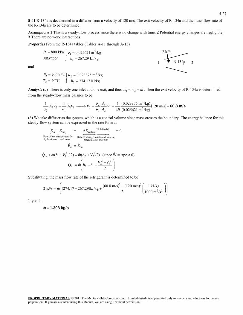
5-41 R-134a is decelerated in a diffuser from a velocity of 120 m/s. The exit velocity of R-134a and the mass flow rate of the R-134a are to be determined.
Assumptions 1 This is a steady-flow process since there is no change with time. 2 Potential energy changes are negligible. 3 There are no work interactions.
Properties From the R-134a tables (Tables A-11 through A-13)
PROPRIETARY MATERIAL. © 2011 The McGraw-Hill Companies, Inc. Limited distribution permitted only to teachers and educators for course
==
⎭⎬⎫=
hvaporsatP v
nd
kPa 900 322 =⎫=P v
Analysis (a) There is only one inlet and one exit, and thus
2 kJ/s
R-134a kJ/kg 267.29
/kgm 0.025621.
kPa 800
1
311
1 2 a
kJ/kg 274.17C40 22 =⎭
⎬°= hT /kgm 0.023375
& & &m m m1 2= = . Then the exit velocity of R-134a is determined om the steady-flow mass balance to be fr
( ) m/s 60.8===⎯→⎯= m/s 120/kg)m (0.0256211.8 31
2
1
1
2211
122
2V
AVVAVA
vvv
/kg)m (0.023375111 3Av
) We take diffuser as the system, which is a control volume since mass crosses the boundary. The energy balance for this eady-flo system can be expressed in the rate form as
(bst w
outin
energies etc. potential, kinetic, internal,in change of Rate
(steady) 0system
mass and work,heat,by nsferenergy tranet of Rate
outin 0
EE
EEE
&&
44 344 21&
43421&&
=
=∆=−
⎟⎟⎠
⎞⎜⎜⎛
= 2in hmQ &&
⎝
−+−
≅∆≅=++
2
0)peW (since /2)V+()2/(2
12
21
2211
VVh
hmVhmQ &&
ubstituting, the mass flow rate of the refrigerant is determined to be
22 &&in
S
( )⎟⎟⎠
⎞⎜⎜⎝
⎛⎟⎟⎠
⎞⎜⎜⎝
⎛−+−= 22
22
/sm 1000kJ/kg 1
2m/s) (120m/s 60.8kg267.29)kJ/(274.17kJ/s 2 m&
It yields
kg/s 1.308=m&
preparation. If you are a student using this Manual, you are using it without permission.
5-28
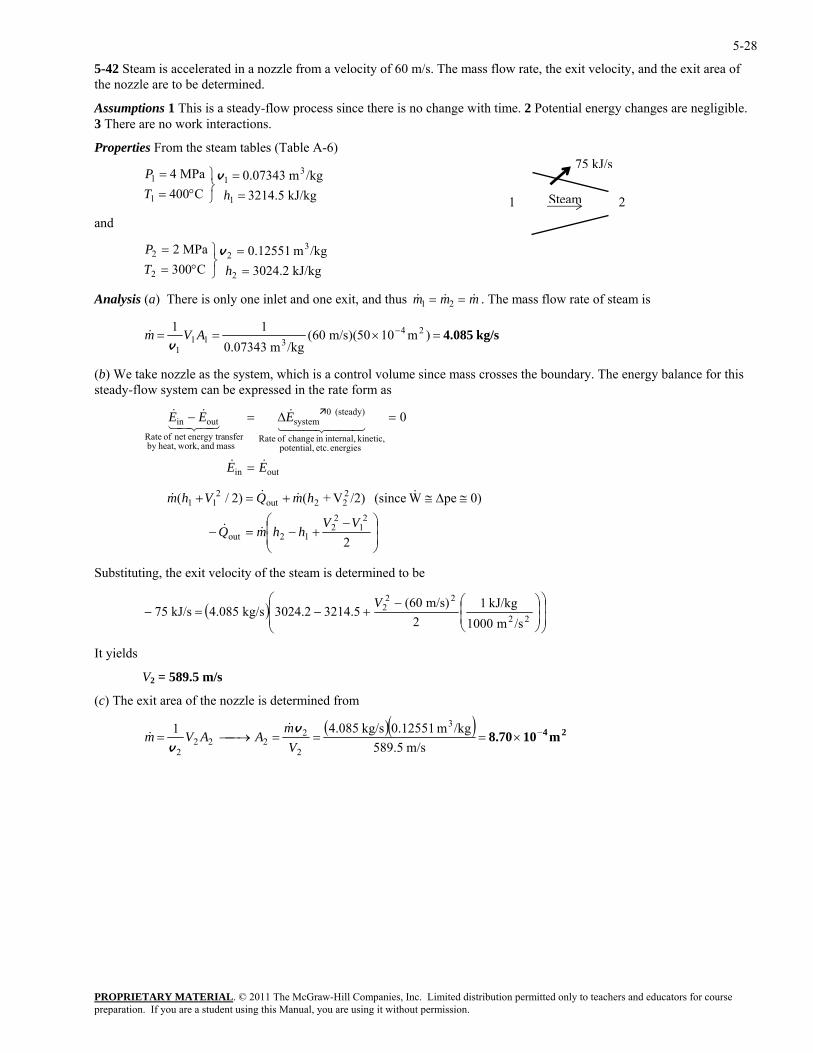
5-42 Steam is accelerated in a nozzle from a velocity of 60 m/s. The mass flow rate, the exit velocity, and the exit area of the nozzle are to be determined.
Assumptions 1 This is a steady-flow process since there is no change with time. 2 Potential energy changes are negligible. 3 There are no work interactions.
Properties From the steam tables (Table A-6)
PROPRIETARY MATERIAL. © 2011 The McGraw-Hill Companies, Inc. Limited distribution permitted only to teachers and educators for course
==
⎭⎬⎫
°==
hTP v
nd
MPa 2 322 =⎫=P v
nalysis (a) There is only one inlet and one exit, and thus
75 kJ/s
Steam1 2 kJ/kg 3214.5/kgm 0.07343
C004MPa 4
1
31
1
1
a
kJ/kg 3024.2C003 22 =⎭
⎬°= hT /kgm 0.12551
A & & &m m m1 2= = . The mass flow rate of steam is
kg/s 4.085=×== − )m1050)(m/s 06(/kgm 0.07343
24311
1AVm
v& 11
) We take nozzle as the system, which is a control volume since mass crosses the boundary. The energy balance for this eady-flo system can be expressed in the rate form as
outin 0
EE
EEE
&&
44 344 21&
43421&&
=
=∆=−
(bst w
of Rateenergies etc. potential,
kinetic, internal,in change of Rate
(steady) 0system
mass and work,heat,by nsferenergy tranet
outin
⎟⎟⎠
⎞⎜⎜⎛
+−=− 212out
VhhmQ &&
⎝
−
≅∆≅+=+
2
0)peW (since /2)V+()2/(2
12
22out11
V
hmQVhm &&&
ined to be
22 &
Substituting, the exit velocity of the steam is determ
( )⎟⎟
⎠
⎞
⎜⎜
⎝
⎛⎟⎟⎠
⎞⎜⎜⎝
⎛−+−=−
22
222
/sm 1000kJ/kg 1
2m/s) (60
3214.53024.2kg/s 4.085kJ/s 75V
It yields
V2 = 589.5 m/s
(c) The exit area of the nozzle is determined from
( )( ) 24 m108.70 −×===⎯→⎯=
m/s 589.5/kgm 0.12551kg/s 4.0851 3
2
2222
2 Vm
AAVmv
v
&&
preparation. If you are a student using this Manual, you are using it without permission.
5-29
Turbines and Compressors
5-43C Yes.
5-44C The volume flow rate at the compressor inlet will be greater than that at the compressor exit.
5-45C Yes. Because energy (in the form of shaft work) is being added to the air.
5-46C No.
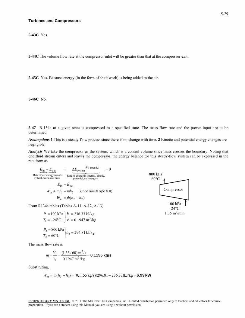
5-47 R-134a at a given state is compressed to a specified state. The mass flow rate and the power input are to be determined.
Assumptions 1 This is a steady-flow process since there is no change with time. 2 Kinetic and potential energy changes are negligible.
Analysis We take the compressor as the system, which is a control volume since mass crosses the boundary. Noting that one fluid stream enters and leaves the compressor, the energy balance for this steady-flow system can be expressed in the rate form as
PROPRIETARY MATERIAL. © 2011 The McGraw-Hill Companies, Inc. Limited distribution permitted only to teachers and educators for course
(steady) 0systemoutin
hhmW
khmhmW
EE
EEE
−=
≅∆≅∆=+
=
=∆=−
&&
&&&
&&
&&&
bles A-11, A-12, A-13)
=⎭⎬⎫
°=h
T
The mass flow rate is
)(
0)pee (since
0
22in
21in
outin
energies etc. potential, kinetic, internal,in change of Rate
mass and work,heat,by nsferenergy tranet of Rate
444 3444 2143421
100 kPa -24°C
1.35 m3/min
800 kPa60°C
Compressor
From R134a tables (Ta
/kgm 1947.0kJ/kg 33.236
C24kPa 100
31
1
1
1
==
⎭⎬⎫
°−==
vh
TP
2 =PkJ/kg 81.296
C60kPa 800
22
kg/s 0.1155===/kgm 0.1947
/sm )60/35.1(3
3
1
1
vV
m&
&
Substituting,
kW 6.99=−=−= .33)kJ/kg23681kg/s)(296. 1155.0()( 12in hhmW &&
preparation. If you are a student using this Manual, you are using it without permission.
5-30
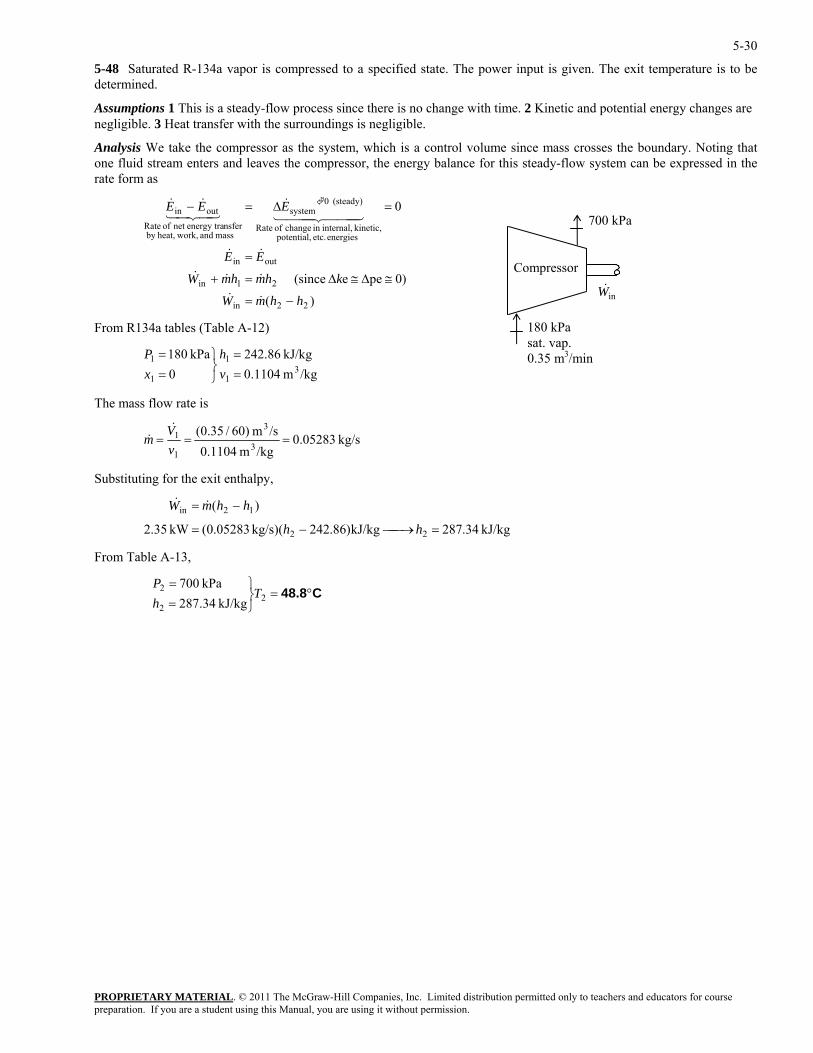
5-48 Saturated R-134a vapor is compressed to a specified state. The power input is given. The exit temperature is to be determined.
Assumptions 1 This is a steady-flow process since there is no change with time. 2 Kinetic and potential energy changes are negligible. 3 Heat transfer with the surroundings is negligible.
Analysis We take the compressor as the system, which is a control volume since mass crosses the boundary. Noting that one fluid stream enters and leaves the compressor, the energy balance for this steady-flow system can be expressed in the rate form as
)(
0)pee (since
0
22in
21in
outin
energies etc. potential, kinetic, internal,in change of Rate
(steady) 0system
mass and work,heat,by nsferenergy tranet of Rate
outin
hhmW
khmhmW
EE
EEE
−=
≅∆≅∆=+
=
=∆=−
&&
&&&
&&
444 3444 21&
43421&&
PROPRIETARY MATERIAL. © 2011 The McGraw-Hill Companies, Inc. Limited distribution permitted only to teachers and educators for course
31 ==
vP
The mass flow rate is
700 kPa
inW&Compressor
180 kPa sat. vap. 0.35 m3/min
From R134a tables (Table A-12)
/kgm 1104.0kJ/kg 86.242
01 ⎭⎬=x
kPa 180 11 ⎫= h
kg/s 05283.0/kgm 0.1104 3
1==
vm& /sm )60/35.0( 3
1 =V&
Substituting for the exit enthalpy,
24kg/s)( 05283.0(kW 35.2
)(
22
12in
=⎯→⎯−=
−
hh
hhm&
From Table A-13,
=W&
kJ/kg 34.287kJ/kg)86.2
C48.8°=⎭⎬⎫
==
22
2
kJ/kg 34.287kPa 700
ThP
preparation. If you are a student using this Manual, you are using it without permission.
5-31
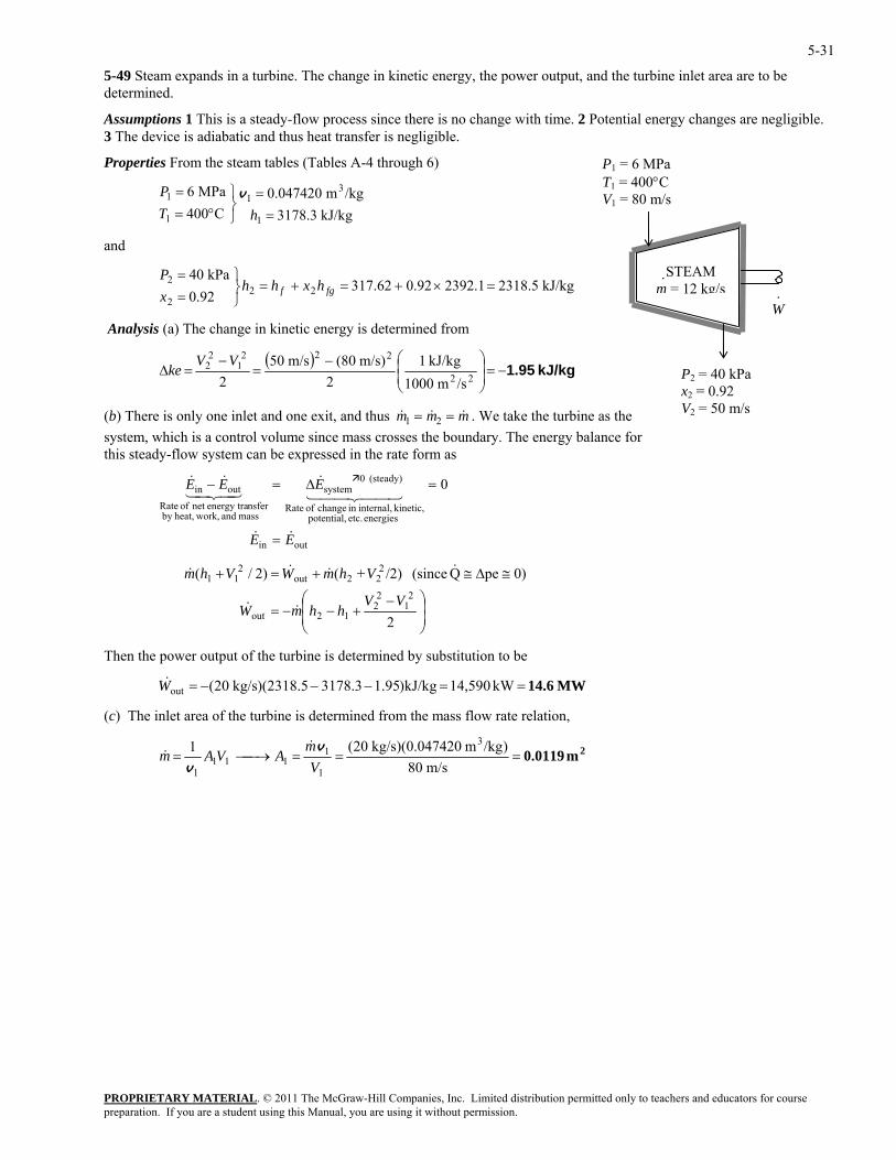
5-49 Steam expands in a turbine. The change in kinetic energy, the power output, and the turbine inlet area are to be determined.
Assumptions 1 This is a steady-flow process since there is no change with time. 2 Potential energy changes are negligible. 3 The device is adiabatic and thus heat transfer is negligible.
Properties From the steam tables (Tables A-4 through 6)
PROPRIETARY MATERIAL. © 2011 The McGraw-Hill Companies, Inc. Limited distribution permitted only to teachers and educators for course
==
⎭⎬⎫
°==
hTP v
and
kPa 402 =⎫=P
Analysis (a) The change in kinetic energy is determined from
P1 = 6 MPa T1 = 400°C V1 = 80 m/s
kJ/kg 3178.3/kgm 0.047420
C400MPa 6
1
31
1
1
W·
STEAM m ·
= 12 kg/s2392.10.9262.31792.0 22
2×+=+=
⎭⎬= fgf hxhh
xkJ/kg 2318.5
( ) kJ/kg 1.95−=⎟⎟⎞
⎜⎜⎝
⎛−=
−=∆
22
2221
22
/sm 1000kJ/kg 1
2m/s) (80m/s 50
2VV
ke P2 = 40 kPa x2 = 0.92 V2 = 50 m/s
⎠
) There is only one inlet and one exit, and thus &(b & &m m m1 2= = . We take the turbine as the system, which is a control volume since mass crosses the boundary. The energy balance for this steady-flow system can be expressed in the rate form as
kinetic, internal,in change of Rate
(steady) 0system
nsferenergy tranet of Rateoutin 0EEE
44 344 21&
43421&& =∆=−
outin
energies etc. potential, mass and work,heat,by
EE && =
≅∆≅+=+ 0)peQ (since /2)+()2/( 222out
211 VhmWVhm &&&&
⎟⎟⎠
⎞⎜⎜⎝
⎛ −+−−=
2
21
22
12outVV
hhmW &&
Then the power output of the turbine is determined by substitution to be
(c) The inlet area of the turbine is determined from the mass flow rate relation,
MW 14.6==−−−= kW 14,590kJ/kg)1.953178.32318.5)(kg/s 20(outW&
2m 0.0119===⎯→⎯=m/s 80
)/kgm 0.047420)(kg/s 20(1 3
1
1111
1 Vm
AVAmv
v
&&
preparation. If you are a student using this Manual, you are using it without permission.
5-32
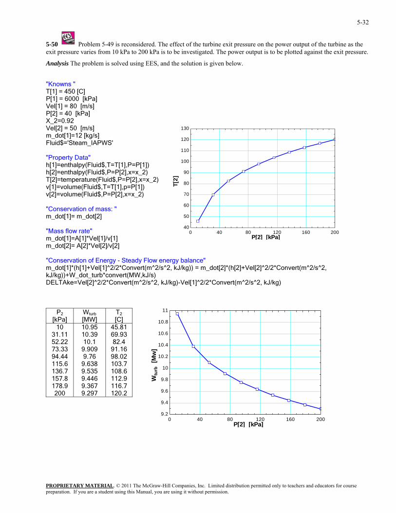
5-50 Problem 5-49 is reconsidered. The effect of the turbine exit pressure on the power output of the turbine as the utput is to be plotted against the exit pressure.
nalysis The problem is solved using EES, and the solution is given below.
PWS'
_2)
ss: "
nvert(m^2/s^2,
ELTAke=Vel[2]^2/2*Convert(m^2/s^2, kJ/kg)-Vel[1]^2/2*Convert(m^2/s^2, kJ/kg)
exit pressure varies from 10 kPa to 200 kPa is to be investigated. The power o
A
"Knowns " T[1] = 450 [C]
a]P[1] = 6000 [kPVel[1] = 80 [m/s] P[2] = 40 [kPa] X_2=0.92 Vel[2] = 50 [m/s]
40
50
60
70
80
90
100
110
120
130m_dot[1]=12 [kg/s] Fluid$='Steam_IA "Property Data" h[1]=enthalpy(Fluid$,T=T[1],P=P[1]) h[2]=enthalpy(Fluid$,P=P[2],x=x_2)
T[2]
T[2]=temperature(Fluid$,P=P[2],x=[1]=volume(Fluid$,T=T[1],p=P[1])
xvv[2]=volume(Fluid$,P=P[2],x=x_2) Conservation of ma"
m_dot[1]= m_dot[2] "Mass flow rate" m_dot[1]=A[1]*Vel[1]/v[1]
0 40 80 120 160 200P[2] [kPa]
m_dot[2]= A[2]*Vel[2]/v[2] "Conservation of Energy - Steady Flow energy balance" m_dot[1]*(h[1]+Vel[1]^2/2*Convert(m^2/s^2, kJ/kg)) = m_dot[2]*(h[2]+Vel[2]^2/2*CoJ/kg))+W_dot_turb*convert(MW,kJ/s) k
D
P2
[kPa] W turb
[MW] T2
[C] 10
31.11 52.22 73.33 94.44 115.6 136.7 157.8 178.9 200 9.297 120.2
10.95 10.39 10.1
9.909 9.76
9.638 9.535 9.446 9.367
45.81 69.93 82.4
91.16 98.02 103.7 108.6 112.9 116.7
9.2
9.4
9.6
9.8
10
10.2
10.4
10.6
10.8
11
Wtu
rb [
Mw
]
0 40 80 120 160 200
P[2] [kPa]
PROPRIETARY MATERIALpreparation. If you are a student using this Manual, you are using it without permission.
. © 2011 The McGraw-Hill Companies, Inc. Limited distribution permitted only to teachers and educators for course
5-33
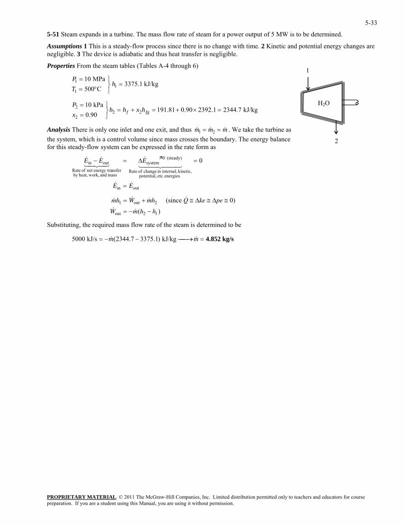
5-51 Steam expands in a turbine. The mass flow rate of steam for a power output of 5 MW is to be determined.
Assumptions 1 This is a steady-flow process since there is no change with time. 2 Kinetic and potential energy changes are negligible. 3 The device is adiabatic and thus heat transfer is negligible.
Properties From the steam tables (Tables A-4 through 6) 1
kJ/kg 3375.1C500
MPa 101
1
1 =⎭⎬⎫
°==
hTP
PROPRIETARY MATERIAL. © 2011 The McGraw-Hill Companies, Inc. Limited distribution permitted only to teachers and educators for course
kPa 01=×
⎫=P H2OkJ/kg
90.0 222
+=+=⎭⎬= fgf hxhh
x
Analysis There is only one inlet and one exit, and thus & & &m m m1 2
2344.72392.10.90.811912
= = . We take the turbine as the sy , which is a control volumfo ad
stem e since mass crosses the boundary. The energy balance r this ste y-flow system can be expressed in the rate form as
0E44 344 21
& =∆=
Substituting, the required mass flow rate of the steam is determined to be
2
energies etc. potential, kinetic, internal,in change of Rate
(steady) 0system
mass and work,heat,by nsferenergy tranet of Rate
outin EE && =
outin EE43421&& −
& & & &
& & ( )
mh W mh Q ke pe
W m h h
1 2
2 1
= + ≅ ≅ ≅
= − −out
out
(since 0)∆ ∆
kg/s 4.852=⎯→⎯−−= mm && kJ/kg )3375.12344.7(kJ/s 5000
preparation. If you are a student using this Manual, you are using it without permission.
5-34
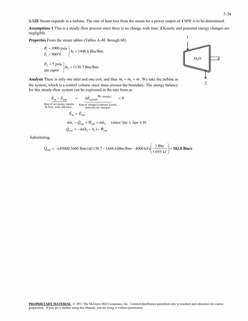
5-52E Steam expands in a turbine. The rate of heat loss from the steam for a power output of 4 MW is to be determined.
Assumptions 1 This is a steady-flow process since there is no change with time. 2 Kinetic and potential energy changes are negligible.
1 Properties From the steam tables (Tables A-4E through 6E)
PROPRIETARY MATERIAL. © 2011 The McGraw-Hill Companies, Inc. Limited distribution permitted only to teachers and educators for course
=⎫=P
H2O
Btu/lbm 1448.6F900psia 1000
11
1 =⎭⎬⎫
°==
hTP
Btu/lbm 1130.7. 2
⎭⎬h
vaporsat
Analysis There is only one inlet and one exit, and thus & & &m m m1 2
psia 52
= = . We take the turbine as 2the sy , which is a control volum
fo adstem e since mass crosses the boundary. The energy balance
r this ste y-flow system can be expressed in the rate form as
0
EE
E
&&
44 344 21&
=
=∆=
Substituting,
outin
energies etc. potential, kinetic, internal,in change of Rate
(steady) 0system
mass and work,heat,by nsferenergy tranet of Rate
outin EE43421&& −
& & & &
& & ( ) &
mh Q W mh ke pe
Q m h h W
1 2
2 1
= + + ≅ ≅
= − − −out out
out out
(since 0)∆ ∆
Btu/s 182.0=⎟⎟⎠
⎞⎜⎜⎝
⎛−−−=
kJ 1.055Btu 1kJ/s 4000Btu/lbm)6.14487.1130)(lbm/s 45000/3600(outQ&
preparation. If you are a student using this Manual, you are using it without permission.
5-35
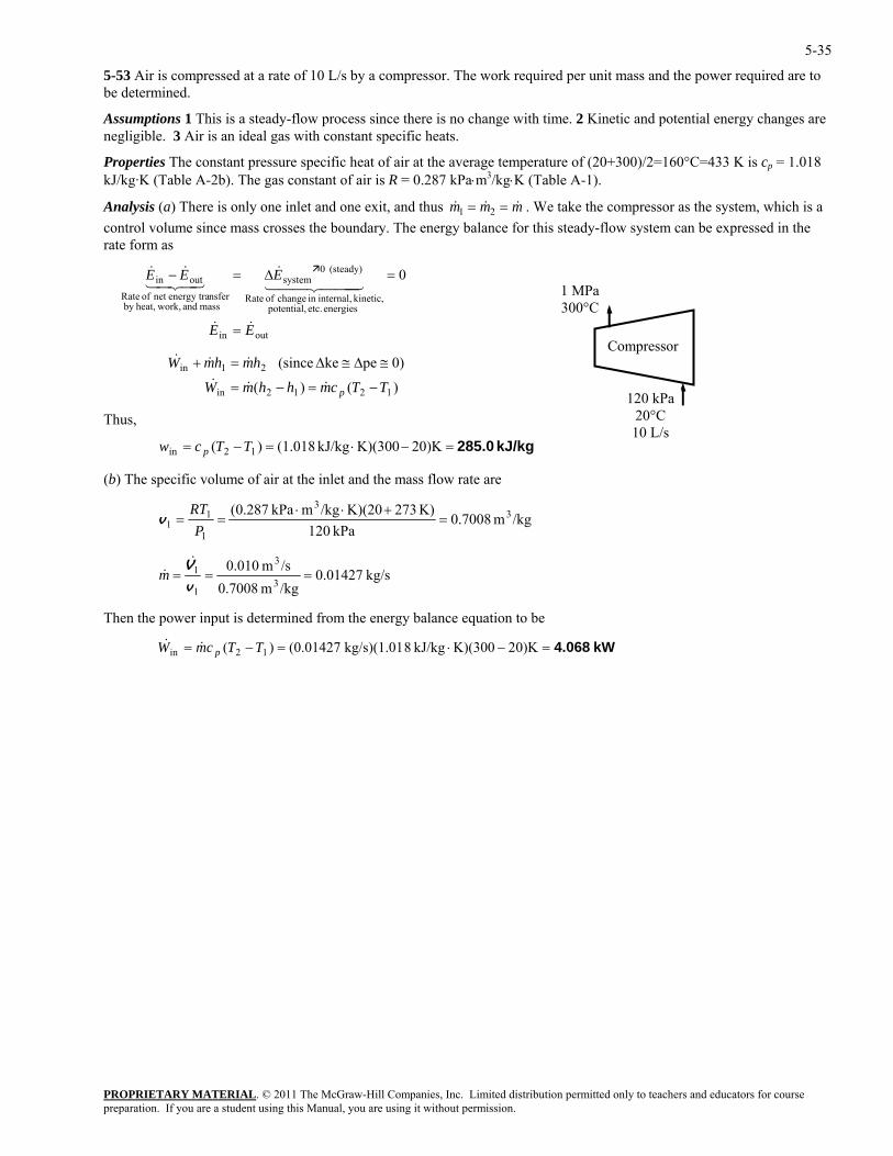
5-53 Air is compressed at a rate of 10 L/s by a compressor. The work required per unit mass and the power required are to be determined.
Assumptions 1 This is a steady-flow process since there is no change with time. 2 Kinetic and potential energy changes are negligible. 3 Air is an ideal gas with constant specific heats.
Properties The constant pressure specific heat of air at the average temperature of (20+300)/2=160°C=433 K is cp = 1.018 kJ/kg·K (Table A-2b). The gas constant of air is R = 0.287 kPa⋅m3/kg⋅K (Table A-1).
Analysis (a) There is only one inlet and one exit, and thus mmm &&& == 21 . We take the compressor as the system, which is a control volume since mass crosses the boundary. The energy balance for this steady-flow system can be expressed in the rate form as
PROPRIETARY MATERIAL. © 2011 The McGraw-Hill Companies, Inc. Limited distribution permitted only to teachers and educators for course
woheat,by
outin
energies etc. potential, kinetic, internal,in change of Rate
(steady) 0system
mass and rk,nsferenergy tranet of Rate
outin 0
EE
EEE
&&
444 344 21&
43421&&
=
=∆=−
p −=−=
≅∆≅∆=+
&&&
&&
120 kPa 20°C 10 L/s
1 MPa 300°C
Compressor W&
)()(
0)peke (since
1212in
21in
TTcmhhmW
hmhm
Thus,
kJ/kg 285.0=−⋅=−= 0)K2K)(300kJ/kg (1.018)( 12in TTcw p
(b) The specific volume of air at the inlet and the mass flow rate are
/kgm 7008.0K) 273K)(20/kgmkPa 287.0( 33
11 =
+⋅⋅==
RTv
kPa 1201P
kg/s 0.01427/kgm 0.7008/sm 010.0
3
3
1
1 ===v
V&&m
Then the power input is determined from the energy balance equation to be
kW 4.068=−⋅=−= 0)K2K)(300kJ/kg 8kg/s)(1.01 (0.01427)( 12in TTcmW p&&
preparation. If you are a student using this Manual, you are using it without permission.
5-36
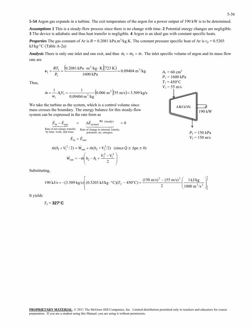
5-54 Argon gas expands in a turbine. The exit temperature of the argon for a power output of 190 kW is to be determined.
Assumptions 1 This is a steady-flow process since there is no change with time. 2 Potential energy changes are negligible. 3 The device is adiabatic and thus heat transfer is negligible. 4 Argon is an ideal gas with constant specific heats.
Properties The gas constant of Ar is R = 0.2081 kPa.m3/kg.K. The constant pressure specific heat of Ar is cp = 0.5203 kJ/kg·°C (Table A-2a)
PROPRIETARY MATERIAL. © 2011 The McGraw-Hill Companies, Inc. Limited distribution permitted only to teachers and educators for course
mAnalysis There is only one inlet and one exit, and thus & &m m1 2& = = . The inlet specific volume of argon and its mass flow rate are
( )( )/kgm 0.09404
kPa 1600K 723K/kgmkPa 0.2081 3
3
1
11 =
⋅⋅==
PRT
v
ARGON
A1 = 60 cm2
P = 1600 kP1
Ta
V1 = 55 m/s
V2 = 150 m/s
190 kW
1 = 450°C
P2 = 150 kPa
Thus,
( )( ) s/
We take the turbine as the system, which is a control volume since mass crosses the boundary. The energy balance for this steady-flow
stem can be expressed in the rate form as
=
at, ork, and mass
system (steady)
Rate of change in internal, kinetic, potential, etc. energies
1 24 34 1 2444 3444∆ 0 0
kg 509.3m/s 55m 0.006/kgm 0.09404
11 2311
1=== VAm
v&
sy
by he w
& & &
& &
E E E
E E
in out
in out
− =
=
Rate of net energy transfer
⎟⎟⎠
⎞⎜⎜⎝
⎛ −+−−=
≅∆≅+=+
2
0)pe (since /2)+()2/(2
12
212out
222out
211
VVhhmW
QVhmWVhm
&&
&&&&
Substituting,
⎥⎥⎦
⎤
⎢⎢⎣
⎡⎟⎟⎠
⎞⎜⎜⎝
⎛−+°−°⋅−= 22
22
2/sm 1000
kJ/kg 12
)m/s 55()m/s 150()C450)(CkJ/kg 0.5203()kg/s .5093(kJ/s 190 T
It yields
T2 = 327°C
preparation. If you are a student using this Manual, you are using it without permission.
5-37
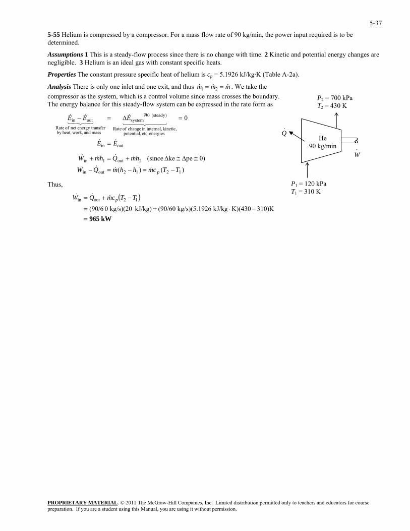
5-55 Helium is compressed by a compressor. For a mass flow rate of 90 kg/min, the power input required is to be determined.
Assumptions 1 This is a steady-flow process since there is no change with time. 2 Kinetic and potential energy changes are negligible. 3 Helium is an ideal gas with constant specific heats.
Properties The constant pressure specific heat of helium is cp = 5.1926 kJ/kg·K (Table A-2a).
PROPRIETARY MATERIAL. © 2011 The McGraw-Hill Companies, Inc. Limited distribution permitted only to teachers and educators for course
mAnalysis There is only one inlet and one exit, and thus & &m m1 2& = = . We take the compressor as the system, which is a control volume since mass crosses the boundarThe energy balance for this steady-flow system can be expressed in the ra
yte form as
outin 0
EE
EEE
&&
44 344 21&
43421&&
=
=∆=−
TTcmhhmQ
hmW
p −=−=−
≅∆≅∆+
&&&
&&
Thus,
. P2 = 700 kPa T2 = 430 K
Rate
outin
energies etc. potential, kinetic, internal,in change of Rate
(steady) 0system
mass and work,heat,by nsferenergy tranet of
W·
He 90 kg/min
·Q
W& )()(
0)peke (since
1212outin
2out1in Qhm =+ &&
P1 = 120 kPa T1 = 310 K
( )
kW965 310)KK)(430kJ/kg 26kg/s)(5.19 (90/60+kJ/kg) kg/s)(20 0 (90/6
12outin
=−⋅=
−+= TTcmQW p&&&
preparation. If you are a student using this Manual, you are using it without permission.
5-38
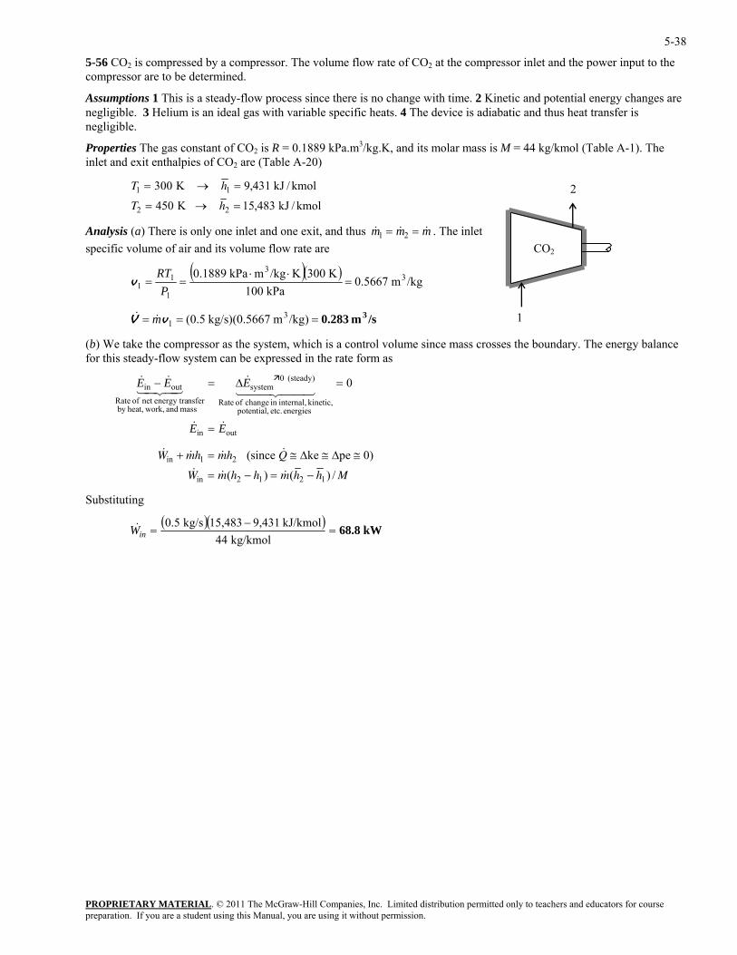
5-56 CO2 is compressed by a compressor. The volume flow rate of CO2 at the compressor inlet and the power input to the compressor are to be determined.
Assumptions 1 This is a steady-flow process since there is no change with time. 2 Kinetic and potential energy changes are negligible. 3 Helium is an ideal gas with variable specific heats. 4 The device is adiabatic and thus heat transfer is negligible.
Properties The gas constant of CO2 is R = 0.1889 kPa.m3/kg.K, and its molar mass is M = 44 kg/kmol (Table A-1). The inlet and exit enthalpies of CO2 are (Table A-20)
T h
PROPRIETARY MATERIAL. © 2011 The McGraw-Hill Companies, Inc. Limited distribution permitted only to teachers and educators for course
T h2 2450 15 483= → = K kJ / kmol,
Analysis (a) There is only one inlet and one exit, an
1 1300 9 431= → = K kJ / kmol,
d thus &
2
& &m m m1 2= = . The inlet ecific vo me of air and its volume flow rate are
sp lu
( )( )/kgm 0.5667
kPa 10011 P
33&
K 300K/kgmkPa 0.1889 33
1 =⋅⋅
==RT
v
)/kgm 0.5667)(kg/s 0.5(1 === vV m&
(b) We take the compressor as the system, which is a control volume since mass crosses the boundary. The energy balance flow system can be expressed in the rate form
0
EE
EEE
&&
44 344 21&
42&&
=
=∆=−
CO2
1 /sm0.283
for this steady- as
net of Rateoutin 341
outin
energies etc. potential, kinetic, internal,in change of Rate
(steady) 0system
mass and work,heat,by nsferenergy tra
& & & &
& & ( ) & ( ) /
W mh mh Q
W m h h m h h M
in
in
(since ke pe 0)+ = ≅ ≅ ≅
= − = −1 2
2 1 2 1
∆ ∆
Substituting
( )( ) kW68.8 kg/kmol 44
kJ/kmol 9,43115,483kg/s 0.5=
−=inW&
preparation. If you are a student using this Manual, you are using it without permission.
5-39
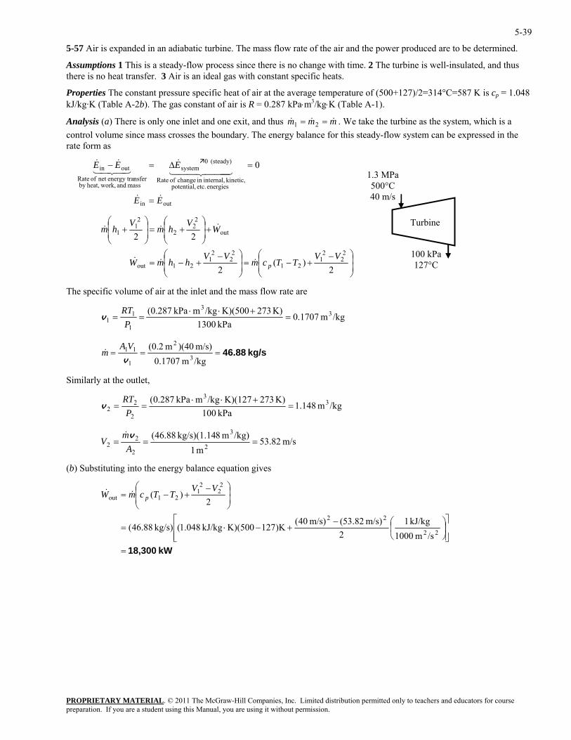
5-57 Air is expanded in an adiabatic turbine. The mass flow rate of the air and the power produced are to be determined.
Assumptions 1 This is a steady-flow process since there is no change with time. 2 The turbine is well-insulated, and thus there is no heat transfer. 3 Air is an ideal gas with constant specific heats.
Properties The constant pressure specific heat of air at the average temperature of (500+127)/2=314°C=587 K is cp = 1.048 kJ/kg·K (Table A-2b). The gas constant of air is R = 0.287 kPa⋅m3/kg⋅K (Table A-1).
Analysis (a) There is only one inlet and one exit, and thus mmm &&& == 21 . We take the turbine as the system, which is a control volume since mass crosses the boundary. The energy balance for this steady-flow system can be expressed in the rate form as
outin
energies etc. potential, kinetic, internal,in change of Rate
(steady) 0system
mass and work,heat,by nsferenergy tranet of Rate
outin 0
EE
EEE
&&
444 344 21&
43421&&
=
=∆=−
⎟⎟⎠
⎞⎜⎜⎝
PROPRIETARY MATERIAL. © 2011 The McGraw-Hill Companies, Inc. Limited distribution permitted only to teachers and educators for course
⎛⎞⎛ − 22
21 VV −
+−=⎟⎟⎠
⎜⎜⎝
+−=
+⎟⎟⎠
⎞⎜⎜⎝
⎛+=⎟
⎟⎠
⎞⎜⎜⎝
⎛+
2)(
2
222
22
12121out
out
22
2
21
1
VVTTcmhhmW
WV
hmV
hm
p&&&
&&&
The specific volume of air at the inlet and the mass flow rate are
/kgm 1707.0kPa 1300
K) 273K)(500/kgmkPa 287.0( 33
1
11 ==
Pv =
+⋅⋅RT
kg/s 46.88===/kgm 0.1707m/s) )(40m 2.0(
3
2
1
11
v
VAm&
Similarly at the outlet,
/kgm 148.1kPa 100
K) 273K)(127/kgmkPa 287.0( 33
2
2 =+⋅⋅
==P
RTv 2
m/s 82.53m 1
/kg)m 8kg/s)(1.14 88.46(2
3
2
22 ===
Am
Vv&
(b) Substituting into the energy balance equation gives
kW 18,300=⎥⎥⎦
⎤
⎢⎢⎣
⎡⎟⎠
⎞⎜⎝
⎛−+−⋅=
⎟⎟⎠
⎞⎜⎜⎝
⎛ −+−=
22
22
22
21
21out
/sm 1000kJ/kg 1
2m/s) 82.53(m/s) 40(
)K127K)(500kJ/kg 048.1(kg/s) 88.46(
2)(
VVTTcmW p&&
100 kPa 127°C
1.3 MPa500°C 40 m/s
Turbine
preparation. If you are a student using this Manual, you are using it without permission.
5-40
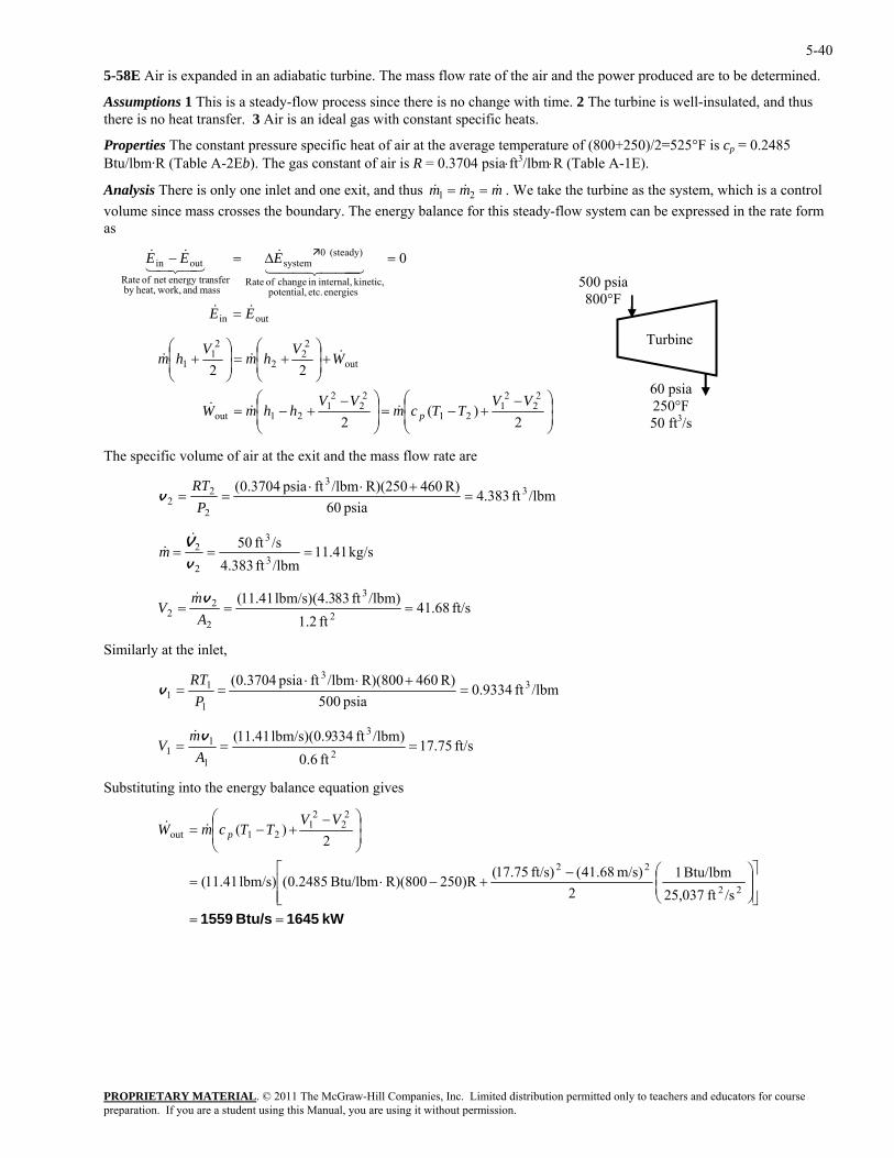
5-58E Air is expanded in an adiabatic turbine. The mass flow rate of the air and the power produced are to be determined.
Assumptions 1 This is a steady-flow process since there is no change with time. 2 The turbine is well-insulated, and thus there is no heat transfer. 3 Air is an ideal gas with constant specific heats.
Properties The constant pressure specific heat of air at the average temperature of (800+250)/2=525°F is cp = 0.2485 Btu/lbm·R (Table A-2Eb). The gas constant of air is R = 0.3704 psia⋅ft3/lbm⋅R (Table A-1E).
Analysis There is only one inlet and one exit, and thus mmm &&& == 21 . We take the turbine as the system, which is a control volume since mass crosses the boundary. The energy balance for this steady-flow system can be expressed in the rate form as
outin
energies etc. potential, kinetic, internal,in change of Rate
(steady) 0system
mass and work,heat,by nsferenergy tranet of Rate
outin 0
EE
EEE
&&
444 344 21&
43421&&
=
=∆=−
PROPRIETARY MATERIAL. © 2011 The McGraw-Hill Companies, Inc. Limited distribution permitted only to teachers and educators for course
⎟⎟⎠
⎞⎜⎜⎝
⎛⎞⎛ − 22
21 VV −
+−=⎟⎟⎠
⎜⎜⎝
+−=
+⎟⎟⎠
⎞⎜⎜⎝
⎛+=⎟
⎟⎠
⎞⎜⎜⎝
⎛+
2)(
2
222
22
12121out
out
22
2
21
1
VVTTcmhhmW
WV
hmV
hm
p&&&
&&&
he specific volume of air at the exit and the m ss flow rate are
60 psia 250°F 50 ft3/s
500 psia 800°F
Turbine
T a
/lbmft 383.4psia 60
R) 460R)(250/lbmftpsia 3704.0( 33
2
2 2 =+⋅⋅
==P
RTv
kg/s 11.41/lbmft 4.383/sft 50
3
3
2
2 ===v
V&&m
ft/s 68.41ft 1.2
/lbm)ft 83lbm/s)(4.3 41.11(2
3
2
2 ===A
mV
v&
Similarly at the inlet,
2
/lbmft 9334.0psia 500
R) 460R)(800/lbmftpsia 3704.0( 33
1
11 =
+⋅⋅==
PRT
v
ft/s 75.17ft 0.6
/lbm)ft 334lbm/s)(0.9 41.11(2
3
1
11 ===
Am
Vv&
Substituting into the energy balance equation gives
kW 1645Btu/s 1559 ==
⎥⎥⎦
⎤
⎢⎢⎣
⎡⎟⎟⎠
⎞⎜⎜⎝
⎛−+−⋅=
⎟⎟⎠
⎞⎜⎜⎝
⎛ −+−=
22
22
22
21
21out
/sft 25,037Btu/lbm 1
2m/s) 68.41(ft/s) 75.17(
)R250R)(800Btu/lbm 2485.0(lbm/s) 41.11(
2)(
VVTTcmW p&&
preparation. If you are a student using this Manual, you are using it without permission.
PROPRIETARY MATERIAL. © 2011 The McGraw-Hill Companies, Inc. Limited distribution permitted only to teachers and educators for course preparation. If you are a student using this Manual, you are using it without permission.
5-41
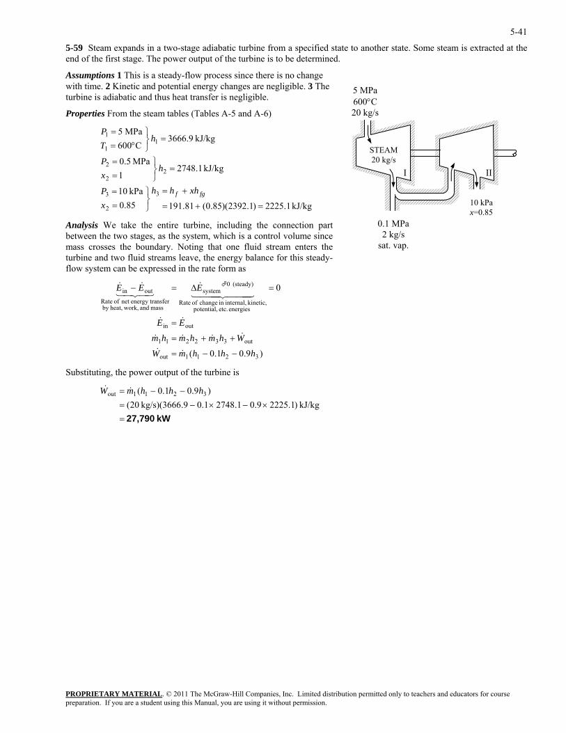
5-59 Steam expands in a two-stage adiabatic turbine from a specified state to another state. Some steam is extracted at the end of the first stage. The power output of the turbine is to be determined.
Assumptions 1 This is a steady-flow process since there is no change with time. 2 Kinetic and potential energy changes are negligible. 3 The turbine is adiabatic and thus heat transfer is negligible.
5 MPa 600°C 20 kg/s Properties From the steam tables (Tables A-5 and A-6)
STEAM 20 kg/s
kPa 10
kJ/kg 1.27481
MPa 0.5
kJ/kg 3666.9C060
33
22
2
11
+=⎫=
=⎭⎬⎫
==
=⎭⎬°=
fgf xhhhP
hxP
hT
II
0.1 MPa 2 kg/s
sat. vap.
10 kPa x=0.85
I
kJ/kg 1.2225)1.2392)(85.0(81.19185.0
MPa 5
2 =+=⎭⎬=
⎫=
x
P
Analysis We take the entire turbine, including the connection part between the two stages, as the system, which is a control volume since mass crosses the boundary. Noting that one fluid stream enters the turbine and two fluid streams leave, the energy balance for this steady-flow system can be expressed in the rate form as
mass and work,heat,b
hhhmW
Whmhmhm
EE
−−=
++=
=
=
&&
&&&&
&&
3
1
)9.01.0(
0
3211out
out332211
outin
energies etc. potential, kinetic, internal,in change of Rate
(steady) 0system
nsferenergy tranet of Rateoutin EEE ∆=−
444444 21
y
&
Substituting, the power output of the turbine is
43421&&
kW 27,790=×−×−=
−−=kJ/kg )1.22259.01.27481.0.9kg/s)(3666 20(
)9.01.0( 3211out hhhmW &&
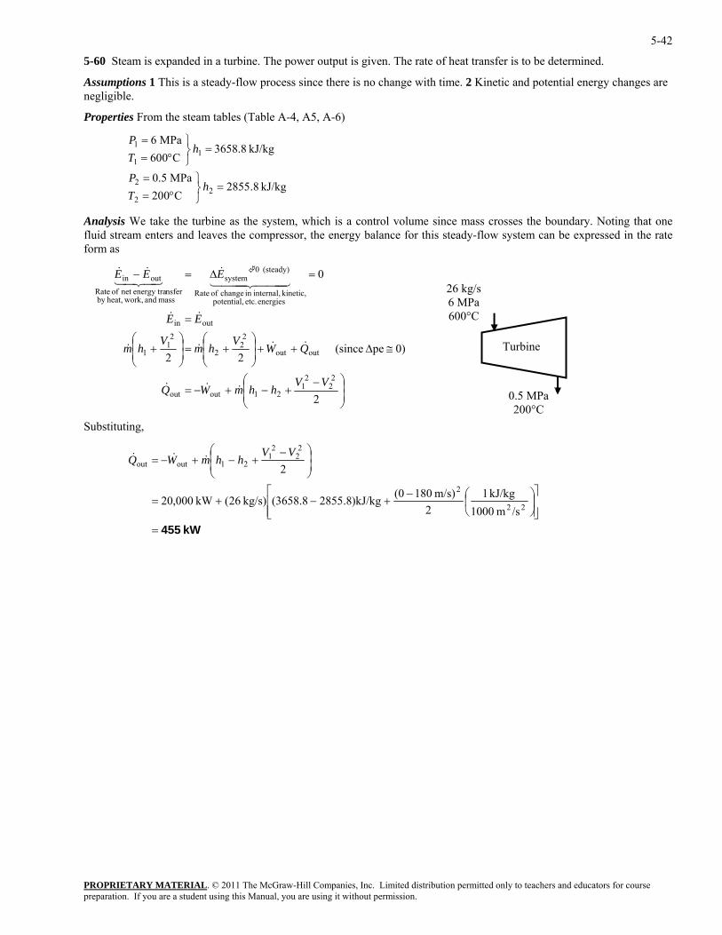
5-42
5-60 Steam is expanded in a turbine. The power output is given. The rate of heat transfer is to be determined.
Assumptions 1 This is a steady-flow process since there is no change with time. 2 Kinetic and potential energy changes are negligible.
Properties From the steam tables (Table A-4, A5, A-6)
kJ/kg 8.2855
C020MPa 5.0
kJ/kg 3658.8C060
MPa 6
22
2
11
1
=⎭⎬⎫
°==
=⎭⎬⎫
°==
hTP
hTP
Analysis We take the turbine as the system, which is a control volume since mass crosses the boundary. Noting that one fluid stream enters and leaves the compressor, the energy balance for this steady-flow system can be expressed in the rate form as
PROPRIETARY MATERIAL. © 2011 The McGraw-Hill Companies, Inc. Limited distribution permitted only to teachers and educators for course
⎟⎟⎠
⎞⎜⎜⎝
⎛ −+−+−=
≅∆++⎟⎟⎠
⎞⎜⎜⎝
⎛+=⎟
⎟⎠
⎞⎜⎜⎝
⎛+
=
=∆=−
2
0)pe (since 22
0
22
21
21outout
outout
22
2
21
1
outin
energies etc. potential, kinetic, internal,in change of Rate
(steady) 0system
mass and work,heat,by energnet of Rate4421
nsfery traoutin
VVhhmWQ
QWV
hmV
hm
EE
EEE
&&&
&&&&
&&
444 3444 21&
3&&
Substituting,
26 kg/s 6 MPa 600°C
0.5 MPa 200°C
Turbine
kW 455=⎥⎥⎦
⎤
⎢⎢⎣
⎡⎟⎠
⎞⎜⎝
⎛−+−+=
⎟⎟⎠
⎞⎜⎜⎝
⎛ −+−+−=
22
2
22
21
21outout
/sm 1000kJ/kg 1
2m/s) 180(0)kJ/kg8.2855(3658.8kg/s) 26(kW 000,20
2VV
hhmWQ &&&
preparation. If you are a student using this Manual, you are using it without permission.

5-43
5-61 Helium at a specified state is compressed to another specified state. The power input is to be determined.
Assumptions 1 This is a steady-flow process since there is no change with time. 2 Kinetic and potential energy changes are negligible. 3 Helium is an ideal gas.
Properties The properties of helium are cp = 5.1926 kJ/kg·K and R = 2.0769 kPa⋅m3/kg⋅K (Table A-2a).
Analysis (a) There is only one inlet and one exit, and thus mmm &&& == 21 . We take the compressor as the system, which is a control volume since mass crosses the boundary. The energy balance for this steady-flow system can be expressed in the rate form as
)()(
0)peke (since
0
1212in
21in
outin
energies etc. potential, kinetic, internal,in change of Rate
(steady) 0system
mass and work,heat,by nsferenergy tranet of Rate
outin
TTcmhhmW
hmhmW
EE
EEE
p −=−=
≅∆≅∆=+
=
=∆=−
&&&
&&&
&&
44 344 21&
43421&&
PROPRIETARY MATERIAL. © 2011 The McGraw-Hill Companies, Inc. Limited distribution permitted only to teachers and educators for course
The mass flow rate is determined from
kg/s 3697.0K) K)(293/kgmkPa (2.0769
kPa) m/s)(150 )(15m 1.0(3
2
1
111
1
11
⋅⋅===m&
RTPVAVA
v
ubstituting,
0)K2K)(200kJ/kg 26)(5.19
he flow p wer input is determined from
150 kPa 20°C
15 m/s
400 kPa200°C
Compressor
S
=−= kg/s 3697.0()( 12in TTcmW p&& kW 346=−⋅
T o
kW 138=−⋅=−=−= 0)K2K)(200kJ/kg 69kg/s)(2.07 3697.0()()( 121122 TTRmPPmW fw &&& vv
preparation. If you are a student using this Manual, you are using it without permission.
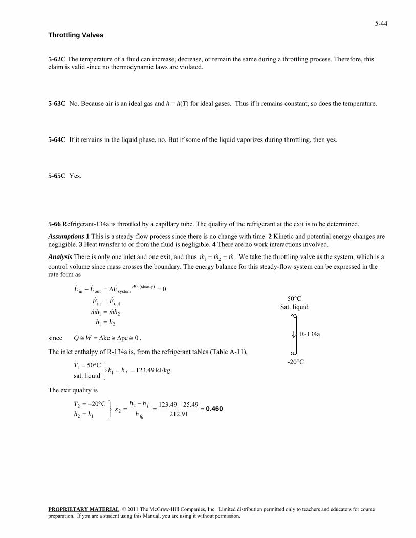
5-44
Throttling Valves
5-62C The temperature of a fluid can increase, decrease, or remain the same during a throttling process. Therefore, this claim is valid since no thermodynamic laws are violated.
5-63C No. Because air is an ideal gas and h = h(T) for ideal gases. Thus if h remains constant, so does the temperature.
5-64C If it remains in the liquid phase, no. But if some of the liquid vaporizes during throttling, then yes.
5-65C Yes.
5-66 Refrigerant-134a is throttled by a capillary tube. The quality of the refrigerant at the exit is to be determined.
Assumptions 1 This is a steady-flow process since there is no change with time. 2 Kinetic and potential energy changes are negligible. 3 Heat transfer to or from the fluid is negligible. 4 There are no work interactions involved.
Analysis There is only one inlet and one exit, and thus mmm &&& == 21 . We take the throttling valve as the system, which is a control volume since mass crosses the boundary. The energy balance for this steady-flow system can be expressed in the rate form as
PROPRIETARY MATERIAL. © 2011 The McGraw-Hill Companies, Inc. Limited distribution permitted only to teachers and educators for course
0
21
21 hmhm = &&outin
(steady) 0systemout
hh
EE
EEE
=
=
=∆=−&&
&&
.
of R-134a is, from the refrigerant tables (Table A-11),
The exit quality is
in&
50°C Sat. liquid
R-134a since ∆=≅WQ && 0∆peke ≅≅
The inlet enthalpy-20°C
kJ/kg 49.123liquid sat.
C501
1 ==⎭⎬⎫°=
fhhT
0.460=−
=−
=⎭⎬⎫
=°−=
91.21249.2549.123
C20 22
12
2
fg
f
hhh
xhh
T
preparation. If you are a student using this Manual, you are using it without permission.
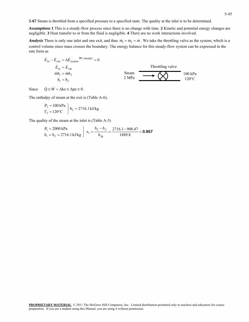
5-45
5-67 Steam is throttled from a specified pressure to a specified state. The quality at the inlet is to be determined.
Assumptions 1 This is a steady-flow process since there is no change with time. 2 Kinetic and potential energy changes are negligible. 3 Heat transfer to or from the fluid is negligible. 4 There are no work interactions involved.
PROPRIETARY MATERIAL. © 2011 The McGraw-Hill Companies, Inc. Limited distribution permitted only to teachers and educators for course
&Analysis There is only one inlet and one exit, and thus mm &&m == 21 . We take the throttling valve as the system, which icontrol volume since mass crosses the boundary. The energy balance for this steady-flow system can be expressed in the rate
s a
form as
WQ & .
2 =⎭⎬⎫
°==
hTP
0
21
21
outin
(steady) 0systemoutin
hhhmhm
EE
EEE
===
=∆=−
&&
&&
&&&
100 kPa 120°C
Throttling valve Steam 2 MPa
Since ≅& 0∆peke ≅≅∆=
The enthalpy of steam at the exit is (Table A-6),
kJ/kg 1.2716C120kPa 100
22
at the inlet is (Table A-5) The quality of the steam
0.957=−
=−
=⎭⎬⎫
===
8.188947.9081.2716
kJ/kg 1.2716kPa 2000 2
121
1
fg
f
hhh
xhh
P
preparation. If you are a student using this Manual, you are using it without permission.
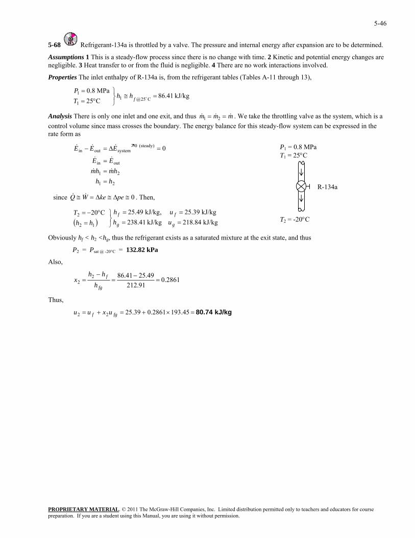
5-46
5-68 Refrigerant-134a is throttled by a valve. The pressure and internal energy after expansion are to be determined.
Assumptions 1 This is a steady-flow process since there is no change with time. 2 Kinetic and potential energy changes are negligible. 3 Heat transfer to or from the fluid is negligible. 4 There are no work interactions involved.
Properties The inlet enthalpy of R-134a is, from the refrigerant tables (Tables A-11 through 13),
kJ/kg 86.41C25 C25@1
1=≅
⎭⎬°=
ofhhT
Analysis There is only one inlet and one exit, and thus & & &m m m
MPa 0.81 ⎫=P
1 2= = . We take the throttling valve as the system, which is a control volume since mass crosses the boundary. The energy balance for this steady-flow system can be expressed in the rate form as
outin
systemoutin
EE
EEE
=
∆=−&&
&&&
ke pe= ≅ ≅∆ ∆ 0 . Then,
=
⎭⎬⎫
=°−=
gg
ff
uhuh
hhT
< h2 <hg, thus the refrigerant exists as a saturated mixture at the exit state, and thus
P2 Psat @ -20°C = 132.82 kPa
lso,
P = 0.8 M1 Pa T1 = 25°C
T2 = -20°C
R-134a
0(steady) 0 =
21 hmhm = &&
21 hh =
since &Q W≅ &
( ) kJ/kg 218.84kJ/kg 238.41kJ/kg 25.39,kJ/kg 25.49C20
12
2
===
Obviously hf
=
A
2861.091.212
49.2541.8622 =
−=
−=
fg
f
hhh
x
Thus,
kJ/kg 80.74=×+=+= 45.1932861.039.2522 fgf uxuu
PROPRIETARY MATERIALpreparation. If you are a student using this Manual, you are using it without permission.
. © 2011 The McGraw-Hill Companies, Inc. Limited distribution permitted only to teachers and educators for course
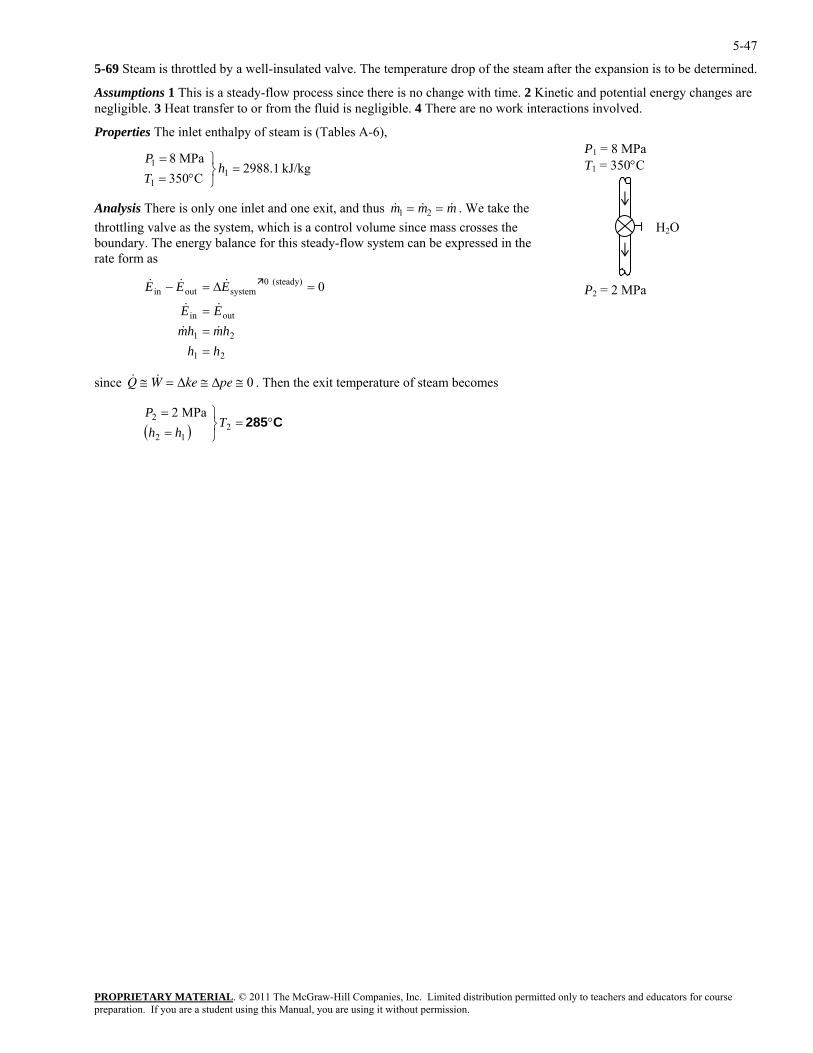
5-47
5-69 Steam is throttled by a well-insulated valve. The temperature drop of the steam after the expansion is to be determined.
Assumptions 1 This is a steady-flow process since there is no change with time. 2 Kinetic and potential energy changes are negligible. 3 Heat transfer to or from the fluid is negligible. 4 There are no work interactions involved.
Properties The inlet enthalpy of steam is (Tables A-6), P1 = 8 MPa T1 = 350°C kJ/kg 1.2988
C035MPa 8
11
1 =⎭⎬⎫
°==
hTP
PROPRIETARY MATERIAL. © 2011 The McGraw-Hill Companies, Inc. Limited distribution permitted only to teachers and educators for course
mAnalysis There is only one inlet and one exit, and thus & &m m1 2& = = . We take thethrottling valve as the system, which is a control volume since mass crosses the boundary. The energy balance for this steady-flow system can be expressed in th
e rate form as
21
outin
(steady) 0systemoutin
hmhmEE
EEE
==
=∆=−
&&
&&
&&&
since . Then the exit temperature of steam becomes
H2O
0 P2 = 2 MPa
21 hh =
& &Q W ke pe≅ = ≅ ≅∆ ∆ 0
( ) C285°=⎭⎬⎫
==
212
2 MPa 2T
hhP
preparation. If you are a student using this Manual, you are using it without permission.
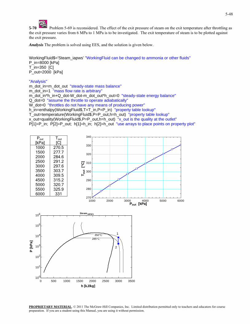
5-48
5-70 Problem 5-69 is reconsidered. The effect of the exit pressure of steam on the exit temperature after throttling athe exit pressu
s re varies from 6 MPa to 1 MPa is to be investigated. The exit temperature of steam is to be plotted against
nalysis The problem is solved using EES, and the solution is given below.
team_iapws' "WorkingFluid can be changed to ammonia or other fluids"
[kPa]
nergy balance"
[1]=P_in; P[2]=P_out; h[1]=h_in; h[2]=h_out "use arrays to place points on property plot"
the exit pressure.
A
WorkingFluid$='SP_in=8000 [kPa]
_in=350 [C] TP_out=2000 "Analysis" m_dot_in=m_dot_out "steady-state mass balance" m_dot_in=1 "mass flow rate is arbitrary" m_dot_in*h_in+Q_dot-W_dot-m_dot_out*h_out=0 "steady-state eQ_dot=0 "assume the throttle to operate adiabatically" W_dot=0 "throttles do not have any means of producing power" h_in=enthalpy(WorkingFluid$,T=T_in,P=P_in) "property table lookup" T_out=temperature(WorkingFluid$,P=P_out,h=h_out) "property table lookup" _out=quality(WorkingFluid$,P=P_out,h=h_out) "x_out is the quality at the outlet" x
P
P out
[kPa] T out
[C] 1000 1500 2000 2500 3000 3500 4000 4500 5000 5500 6000
325.9 331
270.5 277.7 284.6 291.2 297.6 303.7 309.5 315.2 320.7
1000 2000 3000 4000 5000 6000270
280
290
300
310
320
330
340
Pout [kPa]
T out
[°C
]
0 500 1000 1500 2000 2500 3000 3500100
101
102
103
104
105
106
h [kJ/kg]
P [k
Pa] 285°C
350°C
Steam IAPWS
1
2
PROPRIETARY MATERIALpreparation. If you are a student using this Manual, you are using it without permission.
. © 2011 The McGraw-Hill Companies, Inc. Limited distribution permitted only to teachers and educators for course
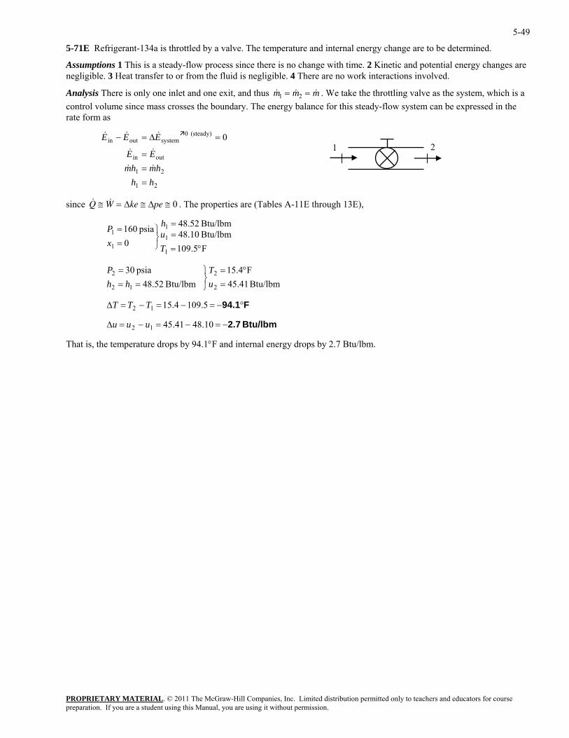
5-49
5-71E Refrigerant-134a is throttled by a valve. The temperature and internal energy change are to be determined.
Assumptions 1 This is a steady-flow process since there is no change with time. 2 Kinetic and potential energy changes are negligible. 3 Heat transfer to or from the fluid is negligible. 4 There are no work interactions involved.
PROPRIETARY MATERIAL. © 2011 The McGraw-Hill Companies, Inc. Limited distribution permitted only to teachers and educators for course
mAnalysis There is only one inlet and one exit, and thus & &m m1 2& = = . We take the throttling valve as the system, which iscontrol volume since mass crosses the boundary. The energy balance for this steady-flow system can be expressed in the rate
a
form as
A-11E through 13E),
0
21
21
outin
(steady) 0systemoutin
hhhmhm
EE
EEE
===
=∆=−
&&
&&
&&&
2 1
since & &W ke pe≅ = ≅ ≅∆ ∆ 0 . The properties are (Tables Q
F5.109Btu/lbm 10.48Btu/lbm 52.48
0psia 160
1
1
1
1
1
°===
⎭⎬⎫
==
Tuh
xP
Btu/lbm 41.45
F4.15 Btu/lbm 52.48
psia 30
2
2
12
2
=°=
⎭⎬⎫
===
uT
hhP
T F94.1°−=−=−=∆ 5.1094.1512 TT
That is, the temperature drops by 94.1°F and internal energy drops by 2.7 Btu/lbm.
Btu/lbm 2.7−=−=−=∆ 10.4841.45uuu 12
preparation. If you are a student using this Manual, you are using it without permission.
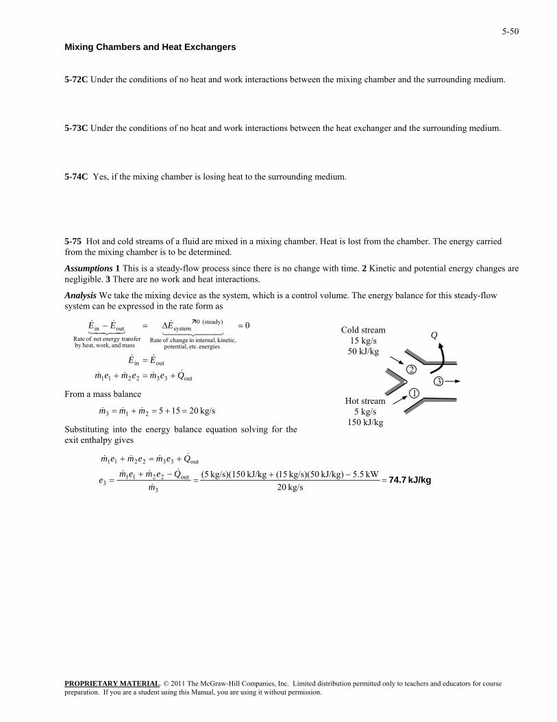
5-50
Mixing Chambers and Heat Exchangers
5-72C Under the conditions of no heat and work interactions between the mixing chamber and the surrounding medium.
5-73C Under the conditions of no heat and work interactions between the heat exchanger and the surrounding medium.
5-74C Yes, if the mixing chamber is losing heat to the surrounding medium.
5-75 Hot and cold streams of a fluid are mixed in a mixing chamber. Heat is lost from the chamber. The energy carried from the mixing chamber is to be determined.
Assumptions 1 This is a steady-flow process since there is no change with time. 2 Kinetic and potential energy changes are negligible. 3 There are no work and heat interactions.
Analysis We take the mixing device as the system, which is a control volume. The energy balance for this steady-flow system can be expressed in the rate form as
out332211
outin
energies etc. potential, kinetic, internal,in change of Rate
(steady) 0system
mass and work,heat,by nsferenergy tranet of Rate
outin 0
Qememem
EE
EEE
&&&&
&&
44 344 21&
43421&&
+=+
=
=∆=−
PROPRIETARY MATERIAL. © 2011 The McGraw-Hill Companies, Inc. Limited distribution permitted only to teachers and educators for course
=+=+= mmm &&
Cold stream 15 kg/s
50 kJ/kg
3 1
2
Hot stream 5 kg/s
150 kJ/kg
Q
From a mass balance
3& kg/s 2015521
Substituting into the energy balance equation solving for the exit enthalpy gives
kJ/kg 74.7=
−+=
−+=
+=+
kg/s 20kW .55kJ/kg) kg/s)(50 15(kJ/kg kg/s)(150 5(
3
out22113
out332211
mQemem
e
Qememem
&
&&&
&&&&
preparation. If you are a student using this Manual, you are using it without permission.
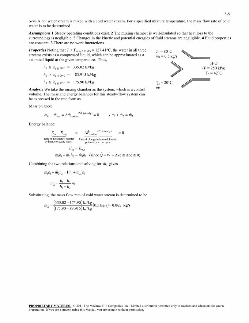
5-51
5-76 A hot water stream is mixed with a cold water stream. For a specified mixture temperature, the mass flow rate of cold water is to be determined.
Assumptions 1 Steady operating conditions exist. 2 The mixing chamber is well-insulated so that heat loss to the surroundings is negligible. 3 Changes in the kinetic and potential energies of fluid streams are negligible. 4 Fluid properties are constant. 5 There are no work interactions.
H2O (P = 250 kPa)
T3 = 42°C
T1 = 80°C m1 = 0.5 kg/s ·
T2 = 20°C m2·
Properties Noting that T < Tsat @ 250 kPa = 127.41°C, the water in all three streams exists as a compressed liquid, which can be approximated as a saturated liquid at the given temperature. Thus,
h1 ≅ hf @ 80°C = 335.02 kJ/kg
h2 ≅ hf @ 20°C = 83.915 kJ/kg
h3 ≅ hf @ 42°C = 175.90 kJ/kg
Analysis We take the mixing chamber as the system, which is a control volume. The mass and energy balances for this steady-flow system can be expressed in the rate form as
Mass balance:
321(steady) 0
systemoutin 0 mmmmmm &&&&&& =+⎯→⎯=∆=−
Energy balance:
0)peke (since
0
332211
outin
energies etc. potential, kinetic, internal,in change of Rate
(steady) 0system
mass and work,heat,by nsferenergy tranet of Rate
outin
≅∆≅∆===+
=
=∆=−
WQhmhmhm
EE
EEE
&&&&&
&&
44 344 21&
43421&&
PROPRIETARY MATERIAL. © 2011 The McGraw-Hill Companies, Inc. Limited distribution permitted only to teachers and educators for course
bining the two relations and solving for gives
hmmhm &&&& +=+
&m2Com
1hm ( ) 321221
& &m h hh h
m21 3
1=−−
3 2
ubstituting, the mass flow rate of cold water stream is determ ed to be
S in
( )( ) ( ) kg/s 0.865=
−−
= kg/s 0.5kJ/kg 83.915175.90kJ/kg 175.90335.02
2m&
preparation. If you are a student using this Manual, you are using it without permission.
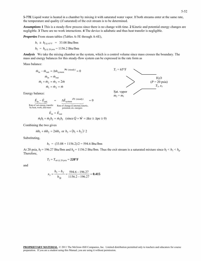
5-52
5-77E Liquid water is heated in a chamber by mixing it with saturated water vapor. If both streams enter at the same rate, the temperature and quality (if saturated) of the exit stream is to be determined.
Assumptions 1 This is a steady-flow process since there is no change with time. 2 Kinetic and potential energy changes are negligible. 3 There are no work interactions. 4 The device is adiabatic and thus heat transfer is negligible.
Properties From steam tables (Tables A-5E through A-6E),
h1 ≅ hf @ 65°F = 33.08 Btu/lbm
h2 = hg @ 20 psia = 1156.2 Btu/lbm
Analysis We take the mixing chamber as the system, which is a control volume since mass crosses the boundary. The mass and energy balances for this steady-flow system can be expressed in the rate form as
Mass balance:
PROPRIETARY MATERIAL. © 2011 The McGraw-Hill Companies, Inc. Limited distribution permitted only to teachers and educators for course
mmm
&&&
&&&&
&
&&
====+
=
=∆=−
21
321
outin
(steady) 0systemout
2
0
gy balance:
outin
energies etc. kinetic, internal,in change
(steady) 0systemoutin
≅∆≅∆===+
=
=∆=−
WQhmhm
EE
EEE
&&&&
&&
44 344 21&
43421&&
3 tu/lbm
hf = 196.27 Btu/lbm and hg = 1156.2 Btu/lbm. Thus the exit stream is a saturated mixture since hf < h3 < hg.
T3 = Tsat @ 20 psia = 228°F
and
H2O (P = 20 psia)
T3, x3
T1 = 65°F
Sat. vapor m2 = m1· ·
& in
mmmmmmm
mm&
Ener
0)peke (since
0
33221
potential, of Rate
mass and work,heat,by nsferenergy tranet of Rate
1hm&
Combining the two gives
( ) 2/or2 213321 hhhhmhmhm +==+ &&&
Substituting,
h = (33.08 + 1156.2)/2 = 594.6 B
At 20 psia, Therefore,
0.415=−−
=−
=27.1962.115627.1966.5943
3fg
f
hhh
x
preparation. If you are a student using this Manual, you are using it without permission.
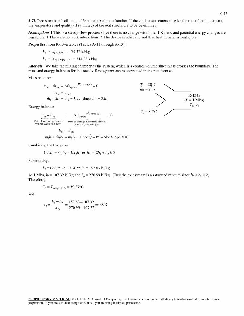
5-53
5-78 Two streams of refrigerant-134a are mixed in a chamber. If the cold stream enters at twice the rate of the hot stream, the temperature and quality (if saturated) of the exit stream are to be determined.
Assumptions 1 This is a steady-flow process since there is no change with time. 2 Kinetic and potential energy changes are negligible. 3 There are no work interactions. 4 The device is adiabatic and thus heat transfer is negligible.
Properties From R-134a tables (Tables A-11 through A-13),
h1 ≅ hf @ 20°C = 79.32 kJ/kg
h2 = h @ 1 MPa, 80°C = 314.25 kJ/kg
Analysis We take the mixing chamber as the system, which is a control volume since mass crosses the boundary. The mass and energy balances for this steady-flow system can be expressed in the rate form as
Mass balance:
PROPRIETARY MATERIAL. © 2011 The McGraw-Hill Companies, Inc. Limited distribution permitted only to teachers and educators for course
2 since 3
0
mmmmmmm
mmm
&&&&&&
&
&&
===+=
=∆=−
Energy balance:
energies etc. potential, kinetic, internal,in change of Rate
(steady) 0system
mass and work,heat,by nsferenergy tranet of Rate
outin
≅∆≅∆===+
=∆=−
WQhmhmh
EEE
&&&&
44 344 21&
43421&&
e two gives
R-134a (P = 1 MPa)
T3, x3
T2 = 80°C
T1 = 20°C m1 = 2m
··2
212321
outin
(steady) 0systemoutin&
m&
outin = EE &&
0)peke (since
0
332211m&
Combining th
( ) /232 213322212 hhhorhmhmhm 3+==+ &&&
×79.32 + 314.25)/3 = 157.63 kJ/kg
Pa, hf = 107.32 kJ/kg and hg = 270.99 kJ/kg. Thus the exit stream is a saturated mixture since hf < h3 < hg. efore,
T3 = Tsat @ 1 MPa = 39.37°C
and
Substituting,
h3 = (2
At 1 MTher
0.307=−−
=−
=32.10799.27032.10763.1573
3fg
f
hhh
x
preparation. If you are a student using this Manual, you are using it without permission.
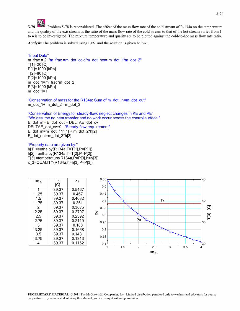
5-54
5-79 Problem 5-78 is reconsidered. The effect of the mass flow rate of the cold stream of R-134a on the temperature and the quality of the exit stream as the ratio of the mass flow rate of the cold stream to that of the hot stream varies from 1
against the cold-to-hot mass flow rate ratio.
nalysis The problem is solved using EES, and the solution is given below.
d/m_dot_hot= m_dot_1/m_dot_2"
*m_dot_2 Pa]
134a: Sum of m_dot_in=m_dot_out"
across the control surface."
ment" m_dot_2*h[2]
])
_3=QUALITY(R134a,h=h[3],P=P[3])
m
to 4 is to be investigated. The mixture temperature and quality are to be plotted
A
"Input Data"m_frac = 2 "m_frac =m_dot_col
T[1]=20 [C] P[1]=1000 [kPa] T[2]=80 [C] P[2]=1000 [kPa]
_fracm_dot_1=mP[3]=1000 [km_dot_1=1 "Conservation of mass for the Rm_dot_1+ m_dot_2 =m_dot_3 "Conservation of Energy for steady-flow: neglect changes in KE and PE" "We assume no heat transfer and no work occurE_dot_in - E_dot_out = DELTAE_dot_cv DELTAE_dot_cv=0 "Steady-flow requireE_dot_in=m_dot_1*h[1] + E_dot_out=m_dot_3*h[3] "Property data are given by:" h[1] =enthalpy(R134a,T=T[1],P=P[1]) h[2] =enthalpy(R134a,T=T[2],P=P[2]) T[3] =temperature(R134a,P=P[3],h=h[3x
frac T 3
[C] x3
1 1.25 1.5
1.75 2
2.25 2.5
2.75 3
3.25 3.5
3.75 4 39.37 0.1162
39.37 39.37 39.37 39.37 39.37 39.37 39.37 39.37 39.37 39.37 39.37 39.37
0.5467 0.467
0.4032 0.351
0.3075 0.2707 0.2392 0.2119 0.188
0.1668 0.1481 0.1313
1 1.5 2 2.5 3 3.5 40.1
0.15
0.2
0.25
0.3
0.35
0.4
0.45
0.5
0.55
30
35
40
45
x 3
T[3]
[C
]
T3
x3
mfrac
PROPRIETARY MATERIALpreparation. If you are a student using this Manual, you are using it without permission.
. © 2011 The McGraw-Hill Companies, Inc. Limited distribution permitted only to teachers and educators for course
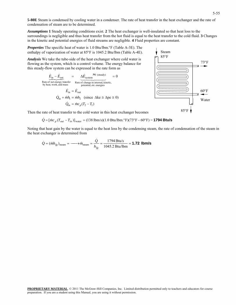
5-55
5-80E Steam is condensed by cooling water in a condenser. The rate of heat transfer in the heat exchanger and the rate of condensation of steam are to be determined.
Assumptions 1 Steady operating conditions exist. 2 The heat exchanger is well-insulated so that heat loss to the surroundings is negligible and thus heat transfer from the hot fluid is equal to the heat transfer to the cold fluid. 3 Changes in the kinetic and potential energies of fluid streams are negligible. 4 Fluid properties are constant.
Properties The specific heat of water is 1.0 Btu/lbm.°F (Table A-3E). The enthalpy of vaporization of water at 85°F is 1045.2 Btu/lbm (Table A-4E).
73°F
60°F Water
Steam 85°F
85°F
Analysis We take the tube-side of the heat exchanger where cold water is flowing as the system, which is a control volume. The energy balance for this steady-flow system can be expressed in the rate form as
)(
0)peke (since
0
12in
21in
outin
energies etc. potential, kinetic, internal,in change of Rate
(steady) 0system
mass and work,heat,by nsferenergy tranet of Rate
outin
TTcmQ
hmhmQ
EE
EEE
p −=
≅∆≅∆=+
=
=∆=−
&&
&&&
&&
44 344 21&
43421&&
Then the rate of heat transfer to the cold water in this heat exchanger becomes
Btu/s 1794=F)60FF)(73Btu/lbm. lbm/s)(1.0 138()]([ water °−°°=−= inoutp TTcmQ &&
Noting that heat gain by the water is equal to the heat loss by the condensing steam, the rate of condensation of the steam in the heat exchanger is determined from
lbm/s 1.72===⎯→⎯==Btu/lbm 2.1045Btu/s 1794)( steamsteam
fgfg h
QmhmQ&
&&&
PROPRIETARY MATERIALpreparation. If you are a student using this Manual, you are using it without permission.
. © 2011 The McGraw-Hill Companies, Inc. Limited distribution permitted only to teachers and educators for course
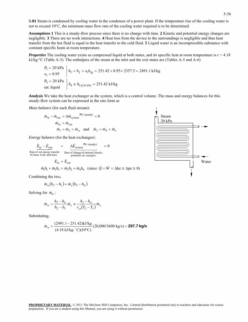
5-56
5-81 Steam is condensed by cooling water in the condenser of a power plant. If the temperature rise of the cooling water is not to exceed 10°C, the minimum mass flow rate of the cooling water required is to be determined.
Assumptions 1 This is a steady-flow process since there is no change with time. 2 Kinetic and potential energy changes are negligible. 3 There are no work interactions. 4 Heat loss from the device to the surroundings is negligible and thus heat transfer from the hot fluid is equal to the heat transfer to the cold fluid. 5 Liquid water is an incompressible substance with constant specific heats at room temperature.
Properties The cooling water exists as compressed liquid at both states, and its specific heat at room temperature is c = 4.18 kJ/kg·°C (Table A-3). The enthalpies of the steam at the inlet and the exit states are (Tables A-5 and A-6)
PROPRIETARY MATERIAL. © 2011 The McGraw-Hill Companies, Inc. Limited distribution permitted only to teachers and educators for course
kPa 20
=
⎫=P
Analysis We take the heat exchanger as the system, which is a control volume. T and energy balances for this steady-flow system can be expressed in the rate form as
Mass balance (for each fluid stream):
mmmmmm
&&&&
&&
===
432
outin
and
0
Energy balance (for the heat exchanger):
outin
energies etc. potential, kinetic, internal,in change of Rate
(steady) 0em
mass and work,heat,by nsferenergy tranet of Rate
ou
≅∆≅∆==+=
=
=∆
WQhmhmhm
EE&&&&&
&&
44 341
kPa 20
kJ/kg 2491.12357.50.95251.4295.0 33
3
⎫=
=×+=+=⎭⎬=
P
hxhhx fgf
3
liquid sat. kPa 20@f44 ≅
⎭⎬ hh kJ/kg 251.42
he mass
Steam 20 kPa
Water
mmm &&& =∆=− (steady) 0systemoutin
wmm && ==1 s
0)peke (since
0
44223311 +hm&
systtin =− EEE4 2&
3
ombining e two,
)
Solving for :
4421&&
C th
( ) ( 4312 hhmhhm sw −=− &&
&mw
( ) sp
sw mTTc
hhm
hhhh
m &&&12
43
12
43
−−
≅−−
=
Substituting,
kg/s 297.7=°⋅
−= )kg/s 020,000/360(
)C10)(CkJ/kg 4.18(kJ/kg)251.422491.1(
o& wm
preparation. If you are a student using this Manual, you are using it without permission.
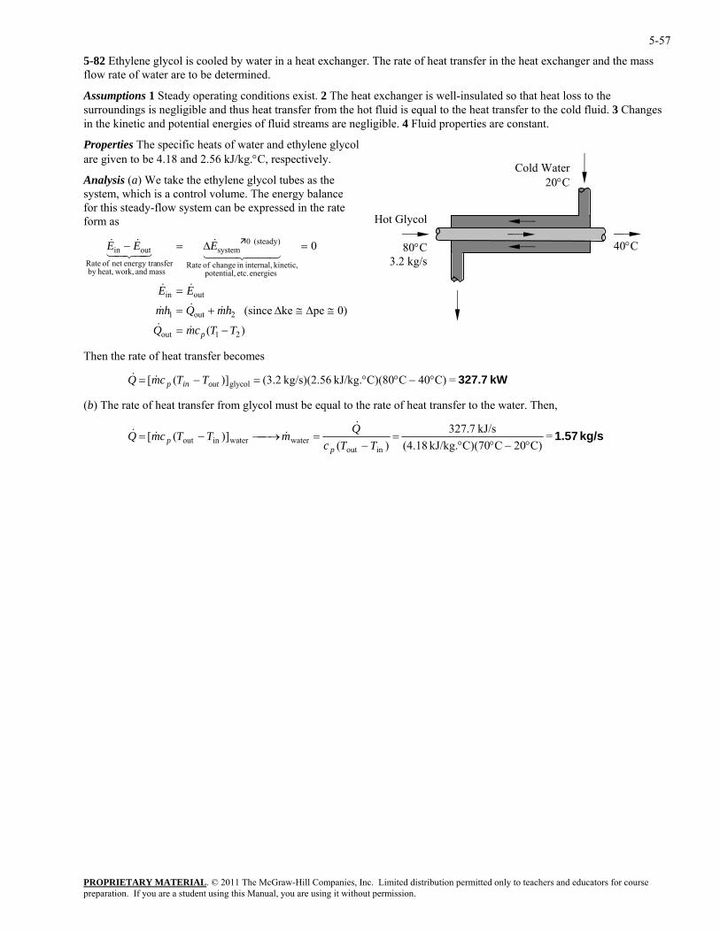
5-57
5-82 Ethylene glycol is cooled by water in a heat exchanger. The rate of heat transfer in the heat exchanger and the mass flow rate of water are to be determined.
Assumptions 1 Steady operating conditions exist. 2 The heat exchanger is well-insulated so that heat loss to the surroundings is negligible and thus heat transfer from the hot fluid is equal to the heat transfer to the cold fluid. 3 Changes in the kinetic and potential energies of fluid streams are negligible. 4 Fluid properties are constant.
Properties The specific heats of water and ethylene glycol are given to be 4.18 and 2.56 kJ/kg.°C, respectively.
40°C
Cold Water 20°C
Hot Glycol
80°C3.2 kg/s
Analysis (a) We take the ethylene glycol tubes as the system, which is a control volume. The energy balance for this steady-flow system can be expressed in the rate form as
)(
0)peke (since
0
21out
2out1
outin
energies etc. potential, kinetic, internal,in change of Rate
(steady) 0system
mass and work,heat,by nsferenergy tranet of Rate
outin
TTcmQ
hmQhm
EE
EEE
p −=
≅∆≅∆+=
=
=∆=−
&&
&&&
&&
44 344 21&
43421&&
Then the rate of heat transfer becomes
kW 327.7=C)40CC)(80kJ/kg. kg/s)(2.56 2.3()]([ glycol °−°°=−= outinp TTcmQ &&
(b) The rate of heat transfer from glycol must be equal to the rate of heat transfer to the water. Then,
kg/s 1.57=C)20CC)(70kJ/kg. (4.18
kJ/s 7.327)(
)]([inout
waterwaterinout °−°°=
−=⎯→⎯−=
TTcQmTTcmQ
pp
&&&&
PROPRIETARY MATERIALpreparation. If you are a student using this Manual, you are using it without permission.
. © 2011 The McGraw-Hill Companies, Inc. Limited distribution permitted only to teachers and educators for course
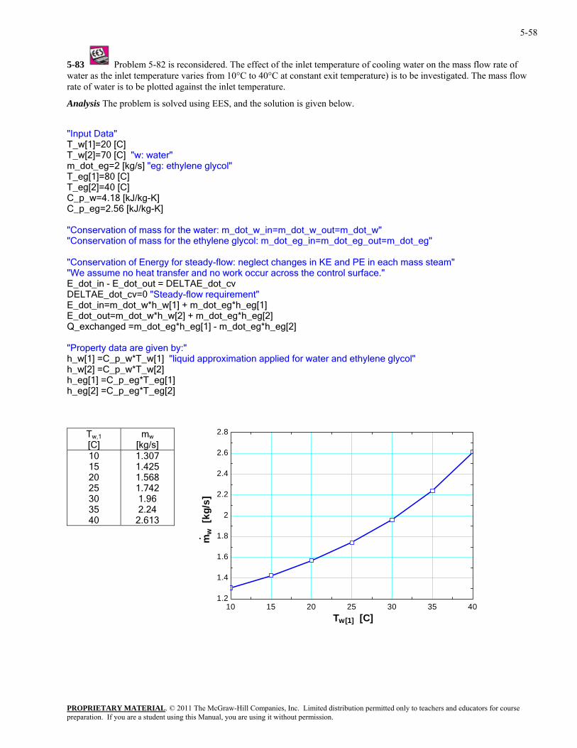
5-58
5-83 Problem 5-82 is reconsidered. The effect of the inlet temperature of cooling water on the mass flow rate of water as the inlet temperature varies from 10°C to 40°C at constant exit temperature) is to be investigated. The mass flow
nalysis The problem is solved using EES, and the solution is given below.
/s] "eg: ethylene glycol"
h mass steam" r across the control surface."
g[1] - m_dot_eg*h_eg[2]
d approximation applied for water and ethylene glycol"
_eg[2] =C_p_eg*T_eg[2]
rate of water is to be plotted against the inlet temperature.
A
"Input Data" T_w[1]=20 [C] T_w[2]=70 [C] "w: water" m_dot_eg=2 [kgT_eg[1]=80 [C] T_eg[2]=40 [C]
_p_w=4.18 [kJ/kg-K] CC_p_eg=2.56 [kJ/kg-K] Conservation of mass for the water: m_dot_w_in=m_dot_w_out=m_dot_w" "
"Conservation of mass for the ethylene glycol: m_dot_eg_in=m_dot_eg_out=m_dot_eg"
neglect changes in KE and PE in eac"Conservation of Energy for steady-flow: "We assume no heat transfer and no work occuE_dot_in - E_dot_out = DELTAE_dot_cv DELTAE_dot_cv=0 "Steady-flow requirement" E_dot_in=m_dot_w*h_w[1] + m_dot_eg*h_eg[1] E_dot_out=m_dot_w*h_w[2] + m_dot_eg*h_eg[2] Q_exchanged =m_dot_eg*h_e "Property data are given by:" h_w[1] =C_p_w*T_w[1] "liquih_w[2] =C_p_w*T_w[2] h_eg[1] =C_p_eg*T_eg[1] h
T w,1
[C] m w
[kg/s] 10 15 20 25 30 35 40 2.613
1.307 1.425 1.568 1.742 1.96 2.24
10 15 20 25 30 35 401.2
1.4
1.6
1.8
2
2.2
2.4
2.6
2.8
mw
[kg
/s]
Tw[1] [C]
PROPRIETARY MATERIALpreparation. If you are a student using this Manual, you are using it without permission.
. © 2011 The McGraw-Hill Companies, Inc. Limited distribution permitted only to teachers and educators for course
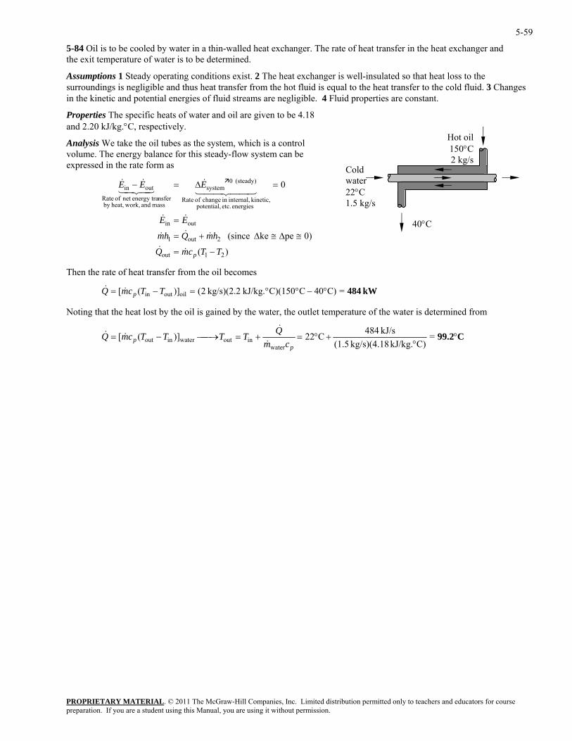
5-59
5-84 Oil is to be cooled by water in a thin-walled heat exchanger. The rate of heat transfer in the heat exchanger and the exit temperature of water is to be determined.
Assumptions 1 Steady operating conditions exist. 2 The heat exchanger is well-insulated so that heat loss to the surroundings is negligible and thus heat transfer from the hot fluid is equal to the heat transfer to the cold fluid. 3 Changes in the kinetic and potential energies of fluid streams are negligible. 4 Fluid properties are constant.
Properties The specific heats of water and oil are given to be 4.18 and 2.20 kJ/kg.°C, respectively.
40°C
Hot oil150°C2 kg/s
Cold water 22°C 1.5 kg/s
Analysis We take the oil tubes as the system, which is a control volume. The energy balance for this steady-flow system can be expressed in the rate form as
)(
0)peke (since
0
21out
2out1
outin
energies etc. potential, kinetic, internal,in change of Rate
(steady) 0system
mass and work,heat,by nsferenergy tranet of Rate
outin
TTcmQ
hmQhm
EE
EEE
p −=
≅∆≅∆+=
=
=∆=−
&&
&&&
&&
44 344 21&
43421&&
Then the rate of heat transfer from the oil becomes
=C)40CC)(150kJ/kg. kg/s)(2.2 2()]([ oiloutin kW 484°−°°=−= TTcmQ p&&
Noting that the heat lost by the oil is gained by the water, the outlet temperature of the water is determined from
C99.2°°
+°=+=⎯→⎯−= =C)kJ/kg. kg/s)(4.18 (1.5
kJ/s 484C22 )]([water
inoutwaterinoutp
p cmQTTTTcmQ
&
&&&
PROPRIETARY MATERIALpreparation. If you are a student using this Manual, you are using it without permission.
. © 2011 The McGraw-Hill Companies, Inc. Limited distribution permitted only to teachers and educators for course
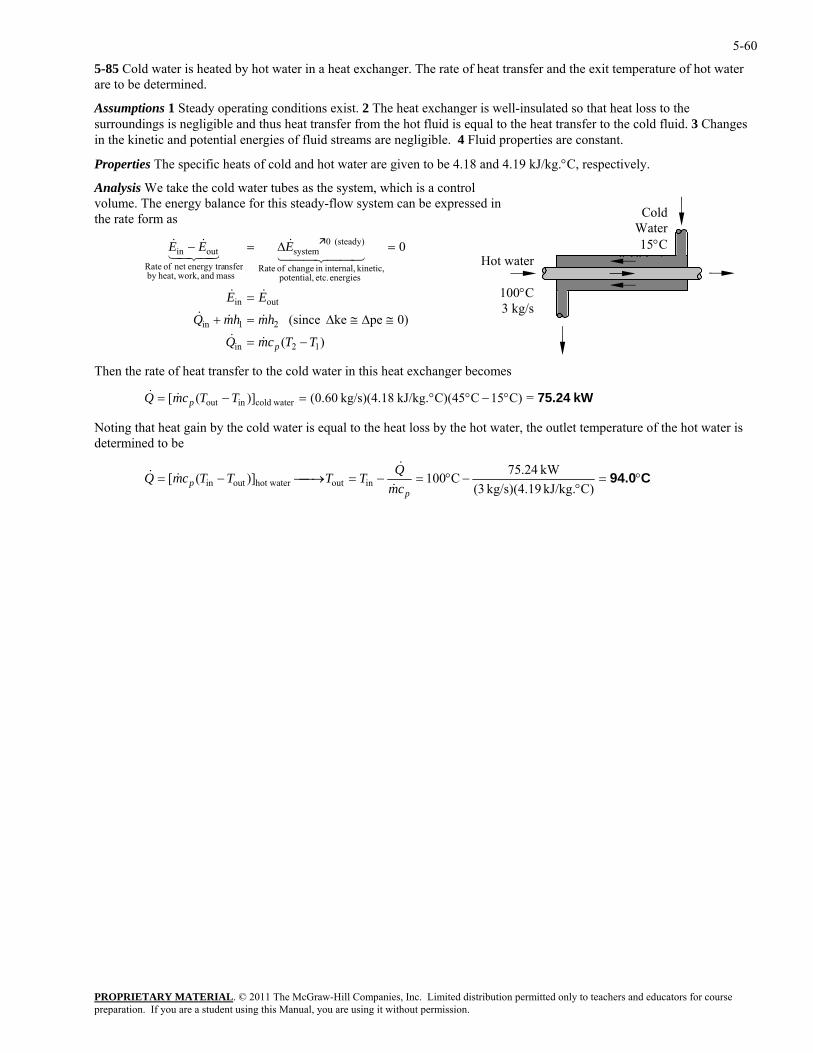
5-60
5-85 Cold water is heated by hot water in a heat exchanger. The rate of heat transfer and the exit temperature of hot water are to be determined.
Assumptions 1 Steady operating conditions exist. 2 The heat exchanger is well-insulated so that heat loss to the surroundings is negligible and thus heat transfer from the hot fluid is equal to the heat transfer to the cold fluid. 3 Changes in the kinetic and potential energies of fluid streams are negligible. 4 Fluid properties are constant.
Properties The specific heats of cold and hot water are given to be 4.18 and 4.19 kJ/kg.°C, respectively.
Analysis We take the cold water tubes as the system, which is a control volume. The energy balance for this steady-flow system can be expressed in the rate form as
PROPRIETARY MATERIAL. © 2011 The McGraw-Hill Companies, Inc. Limited distribution permitted only to teachers and educators for course
0
12in
outin
(steady) 0systemoutin
TTcmQ
EE
EEE
p −=
=
=∆=−
&&
&&
&&&
Then the rate of heat transfer to the cold water in this heat exchanger becomes
Noting that heat gain by the cold water is equal to the heat loss by the hot water, the outlet temperature of the hot water is determined to be
Cold Water15°C
0 60 k /energies etc. potential,
kinetic, internal,in change of Ratemass and work,heat,by
nsferenergy tranet of Rate44 344 2143421 Hot water
100°C3 kg/s
0)peke (since 21in hmhmQ ≅∆≅∆=+ &&&
)(
kW 75.24=C)15CC)(45kJ/kg. kg/s)(4.18 60.0()]([ watercoldinout °−°°=−= TTcmQ p&&
C94.0°=°
−°=−=⎯→⎯−=C)kJ/kg. kg/s)(4.19 3(
kW 24.75C100)]([ inouthot wateroutinp
p cmQTTTTcmQ&
&&&
preparation. If you are a student using this Manual, you are using it without permission.
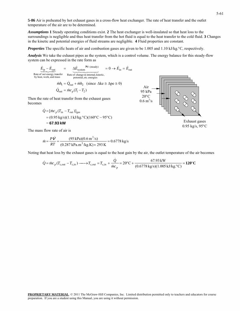
5-61
5-86 Air is preheated by hot exhaust gases in a cross-flow heat exchanger. The rate of heat transfer and the outlet temperature of the air are to be determined.
Assumptions 1 Steady operating conditions exist. 2 The heat exchanger is well-insulated so that heat loss to the surroundings is negligible and thus heat transfer from the hot fluid is equal to the heat transfer to the cold fluid. 3 Changes in the kinetic and potential energies of fluid streams are negligible. 4 Fluid properties are constant.
Properties The specific heats of air and combustion gases are given to be 1.005 and 1.10 kJ/kg.°C, respectively.
Analysis We take the exhaust pipes as the system, which is a control volume. The energy balance for this steady-flow system can be expressed in the rate form as
)(
0)peke (since
0
21out
2out1
outin
energies etc. potential, kinetic, internal,in change of Rate
(steady) 0system
mass and work,heat,by nsferenergy tranet of Rate
outin
TTcmQ
hmQhm
EEEEE
p −=
≅∆≅∆+=
=→=∆=−
&&
&&&
&&44 344 21
&43421&&
PROPRIETARY MATERIAL. © 2011 The McGraw-Hill Companies, Inc. Limited distribution permitted only to teachers and educators for course
)]([ gasoutin
°−°°
− TTcmQ p&
The mass flow rate of air is
Air 95 kPa 20°C
0.6 m3/sThen the rate of heat transfer from the exhaust gases becomes
=&
kW 67.93=C)95CC)(160kJ/kg. kg/s)(1.1 95.0(=
Exhaust gases 0.95 kg/s, 95°C
kg/s 6778.0/s)m kPa)(0.6 (95 3===
Pm V&&
K 293/kg.K)kPa.m 287.0( 3 ×RT
oting that heat loss by the exhaust gases is equal to the heat gain by the air, the outlet temperature of the air becomes N
C120°=°
+°=+=⎯→⎯−=C)kJ/kg. 5kg/s)(1.00 6778.0(
kW 93.67C20)( inc,outc,inc,outc,p
p cmQTTTTcmQ&
&&&
preparation. If you are a student using this Manual, you are using it without permission.
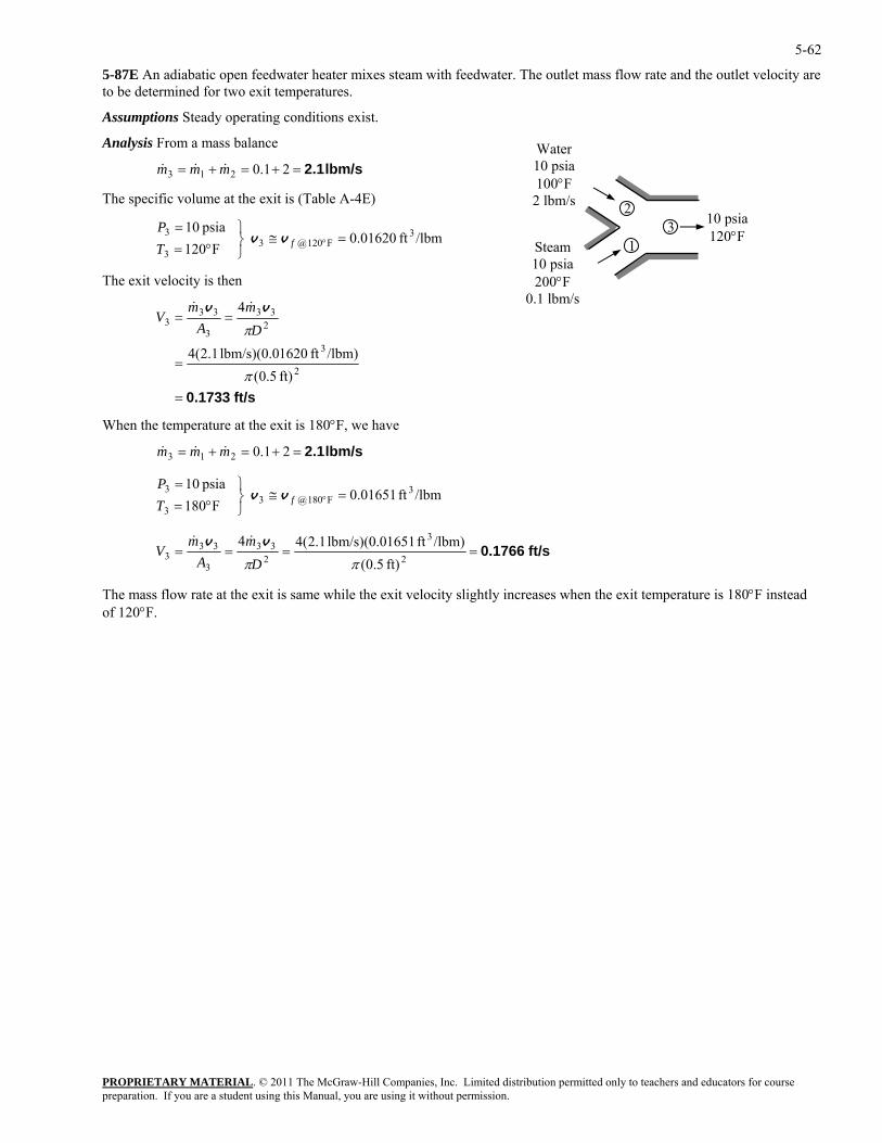
5-62
5-87E An adiabatic open feedwater heater mixes steam with feedwater. The outlet mass flow rate and the outlet velocity are to be determined for two exit temperatures.
Assumptions Steady operating conditions exist.
Analysis From a mass balance
PROPRIETARY MATERIAL. © 2011 The McGraw-Hill Companies, Inc. Limited distribution permitted only to teachers and educators for course
psia 10 3F120@3 =≅
⎫=°f
Pvv
The exit velocity is then
Steam 10 psia 200°F
0.1 lbm/s
3 1
2 10 psia 120°F
Water 10 psia 100°F 2 lbm/s
lbm/s 2.1=+=+= 21.0213 mmm &&&
The specific volume at the exit is (Table A-4E)
/lbmft 01620.0 F1203 ⎭
⎬°=T3
ft/s 0.1733=
=
==
2
3
233
3
333
ft) 5.0(/lbm)ft 1620lbm/s)(0.0 1.2(4
4
π
πDm
Am
Vvv &&
hen the temperature at the exit is 180°F, we have
=≅⎭⎬⎫
°==
°fTP
vv
W
lbm/s 2.1=+=+= 21.0213 mmm &&&
/lbmft 01651.0 F180 psia 10 3
F180@33
3
ft/s 0.1766====2
34mmV
vv &&2
33
3
333
ft) 5.0(/lbm)ft 1651lbm/s)(0.0 1.2(4
ππDA
he mass flow rate at the exit is same while the exit velocity slightly increases when the exit temperature is 180°F instead of 120°F.
T
preparation. If you are a student using this Manual, you are using it without permission.
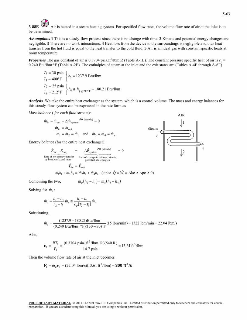
5-63
5-88E Air is heated in a steam heating system. For specified flow rates, the volume flow rate of air at the inlet is to be determined.
Assumptions 1 This is a steady-flow process since there is no change with time. 2 Kinetic and potential energy changes are negligible. 3 There are no work interactions. 4 Heat loss from the device to the surroundings is negligible and thus heat transfer from the hot fluid is equal to the heat transfer to the cold fluid. 5 Air is an ideal gas with constant specific heats at room temperature.
Properties The gas constant of air is 0.3704 psia.ft3/lbm.R (Table A-1E). The constant pressure specific heat of air is cp = 0.240 Btu/lbm·°F (Table A-2E). The enthalpies of steam at the inlet and the exit states are (Tables A-4E through A-6E)
psia 25
Btu/lbm 1237.9F400 3
3
⎫=
=⎭⎬°=
P
hT
PROPRIETARY MATERIAL. © 2011 The McGraw-Hill Companies, Inc. Limited distribution permitted only to teachers and educators for course
Btu/lbm 180.21F212 F212@4
4
4 =≅⎭⎬°=
ofhhT
psia 30 ⎫=P
Analysis We take the entire heat exchanger as the system, which is a control volume. The mass and energy balances for this steady-flow system can be expressed in the rate f as
Mass balance ( for each fluid stream):
mmm
&&&&
&&
===
432
outin
and
e en heat exchanger):
e two,
3
orm
sa mmmmm && ==1
mmm &&& =∆=− (steady) 0systemoutin 0
Energy balance (for th tire
0)peke (since
0
44223311
outin
energies etc. potential, kinetic, internal,in change of Rate
(steady) 0system
mass and work,heat,by nsferenergy tranet of Rate
outin
≅∆≅∆==+=+
=
=∆=−
WQhmhmhmhm
EE
EEE
&&&&&&
&&
44 344 21&
43421&&
AIR
Steam
3
4
1
2
( ) ( )4312 hhmhhm sa −=− && Combining th
Solving for : &ma
( ) sp
sa mTTc
mhh
m &&&12
43
12
43
−≅
−= hhhh −−
bstitutin ,
Su g
lbm/s 22.04lbm/min 1322)lbm/min 15(F)80130)(FBtu/lbm 0.240(
Btu/lbm)180.211237.9(==
°−°⋅−
=am&
Also,
/lbmft 13.61psia 14.7
)R 540)(R/lbmftpsia 0.3704( 33
1
11 =
⋅⋅==
PRT
v
Then the volume flow rate of air at the inlet becomes
/sft 300 3=== )/lbmft 13.61)(lbm/s 22.04( 311 vV am&&
preparation. If you are a student using this Manual, you are using it without permission.
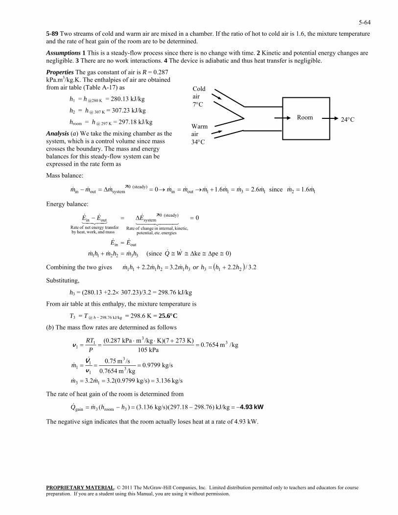
5-64
5-89 Two streams of cold and warm air are mixed in a chamber. If the ratio of hot to cold air is 1.6, the mixture temperature and the rate of heat gain of the room are to be determined.
Assumptions 1 This is a steady-flow process since there is no change with time. 2 Kinetic and potential energy changes are negligible. 3 There are no work interactions. 4 The device is adiabatic and thus heat transfer is negligible.
Properties The gas constant of air is R = 0.287 kPa.m3/kg.K. The enthalpies of air are obtained from air table (Table A-17) as Cold
air 7°C
Room Warm air 34°C
h1 = h @280 K = 280.13 kJ/kg
h2 = h @ 307 K = 307.23 kJ/kg 24°C hroom = h @ 297 K = 297.18 kJ/kg
Analysis (a) We take the mixing chamber as the system, which is a control volume since mass crosses the boundary. The mass and energy balances for this steady-flow system can be expressed in the rate form as
Mass balance:
121311outin(steady) 0
systemoutin 6.1 since 6.26.1 0 mmmmmmmmmmm &&&&&&&&&&& ===+→=→=∆=−
Energy balance:
PROPRIETARY MATERIAL. © 2011 The McGraw-Hill Companies, Inc. Limited distribution permitted only to teachers and educators for course
0
outin
energies etc. potential, kinetic, internal,in change of Rate
(steady) 0systemoutin
≅∆≅
=
=∆=−
EE
EEE
&&
44 344 21&&&
mass and work,heat,by nsferenergy tranet of Rate
43421
(since 332211 ∆≅≅=+ WQhmhmhm &&&&& 0)peke
( ) 2.3/2.22.32.2 312111 orhmhmhm 213 hhh +=Combining the two gives =+ &&&
bstitut
3 kg
air table at this enthalpy, the mixture temperature is
3 @ h = 298.76 kJ/kg
) The mass flow rates are determined as follows
Su ing,
h = (280.13 +2.2× 307.23)/3.2 = 298.76 kJ/
From
T = T = 298.6 K = 25.6°C
(b
kg/s .1363kg/s) 9799.0(2.32.3
kg/s 9799.0/kgm 0.7654/sm 0.75
kg/m 7654.0kPa 105
K) 273K)(7/kgmkPa (0.287 33
1 +⋅⋅RT
13
3
3
1
11
1
===
===
===
mm
m
P
&&
&&
v
V
v
The rate of heat gain of the room is determined from
The negative sign indicates that the room actually loses heat at a rate of 4.93 kW.
kW 4.93−=−=−= kJ/kg )76.29818.297(kg/s) 136.3()( 3room3gain hhmQ &&
preparation. If you are a student using this Manual, you are using it without permission.
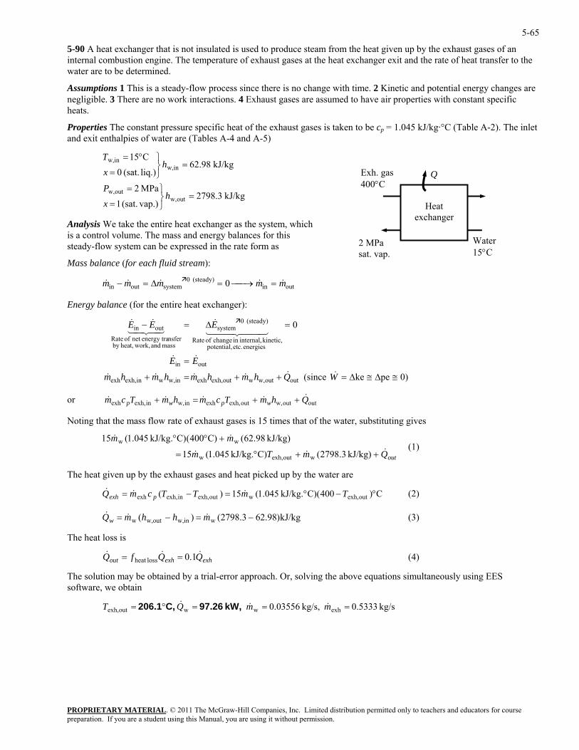
5-65
5-90 A heat exchanger that is not insulated is used to produce steam from the heat given up by the exhaust gases of an internal combustion engine. The temperature of exhaust gases at the heat exchanger exit and the rate of heat transfer to the water are to be determined.
Assumptions 1 This is a steady-flow process since there is no change with time. 2 Kinetic and potential energy changes are negligible. 3 There are no work interactions. 4 Exhaust gases are assumed to have air properties with constant specific heats.
Properties The constant pressure specific heat of the exhaust gases is taken to be cp = 1.045 kJ/kg·°C (Table A-2). The inlet and exit enthalpies of water are (Tables A-4 and A-5)
PROPRIETARY MATERIAL. © 2011 The McGraw-Hill Companies, Inc. Limited distribution permitted only to teachers and educators for course
in ⎫°=T
Analysis We take the entire heat exchanger as the system, which is a control volume. The mass and energy balances for this
orm as
Mass balance (for each fluid stream):
outin
(steady) 0system
≅∆≅∆=
=
=∆=
Wm
EE
E
&&
&&
44 344 21&
QhmTcmhm wpw&&&& ++=+
oting that the mass flow rate of exha
&&& ++°= kJ/kg) 3.2798(C)kJ/kg. 045.1(15 woutexh,w
gi the exhaust gases and heat picked up by the water are
(2)
(3)
The heat loss is
(4)
The solution may be obtained by a trial-error approach. Or, solving the above equations simultaneously using EES software, we obtain
kJ/kg 3.2798MPa 2
kJ/kg 98.62liq.) (sat. 0
outw,outw,
inw,
=⎬⎫=
=⎭⎬
=
hP
hx
C15w,
Q
2 MPa sat. vap.
Heat exchanger
Exh. gas 400°C
Water15°C
vap.)(sat. 1 ⎭=x
steady-flow system can be expressed in the rate f
outin(steady) 0
systemoutin 0 mmmmm &&&&& =⎯→⎯=∆=−
Energy balance (for the entire heat exchanger):
0)peke (since
0
out
energies etc. potential, kinetic, internal,in change of Rate
mass and work,heat,by nsferenergy tranet of Rate
outin − EE43421&&
outw,woutexh,exhinw,winexh,exh ++=+ Qhmhmhmh &&&&
or exh Tcm p& outoutw,outexh,exhinw,inexh,
N ust gases is 15 times that of the water, substituting gives
outQmTm
mm && +°°
kJ/kg) 98.62(C)400(C)kJ/kg. 045.1(15 ww (1)
The heat ven up by
C)400C)(kJ/kg. 045.1(15)( outexh,woutexh,inexh,exh °−°=−= TmTTcmQ pexh &&&
kJ/kg)98.623.2798()( winw,outw,w −=−= mhhmQw &&&
exhexhout QQfQ &&& 1.0lossheat ==
kg/s 5333.0 kg/s, 03556.0 exhwwoutexh, ===°= mmQT &&& kW, 97.26 C,206.1
preparation. If you are a student using this Manual, you are using it without permission.
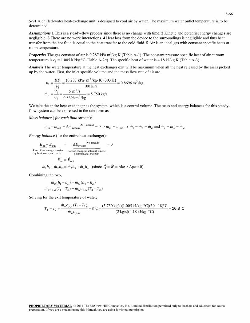
5-66
5-91 A chilled-water heat-exchange unit is designed to cool air by water. The maximum water outlet temperature is to be determined.
Assumptions 1 This is a steady-flow process since there is no change with time. 2 Kinetic and potential energy changes are negligible. 3 There are no work interactions. 4 Heat loss from the device to the surroundings is negligible and thus heat transfer from the hot fluid is equal to the heat transfer to the cold fluid. 5 Air is an ideal gas with constant specific heats at room temperature.
Properties The gas constant of air is 0.287 kPa.m3/kg.K (Table A-1). The constant pressure specific heat of air at room temperature is cp = 1.005 kJ/kg·°C (Table A-2a). The specific heat of water is 4.18 kJ/kg⋅K (Table A-3).
Analysis The water temperature at the heat exchanger exit will be maximum when all the heat released by the air is picked up by the water. First, the inlet specific volume and the mass flow rate of air are
kg/s 750.5
/kgm 0.8696/sm 5
/kgm 0.8696kPa 100
)K 303)(K/kgmkPa 0.287(
3
3
1
1
33
1
11
===
=⋅⋅
==
v
V
v
&& am
PRT
We take the entire heat exchanger as the system, which is a control volume. The mass and energy balances for this steady-flow system can be expressed in the rate form as
Mass balance ( for each fluid stream):
wa mmmmmmmmmmm &&&&&&&&&&& ====→=→=∆=− 4231outin(steady) 0
systemoutin and 0
Energy balance (for the entire heat exchanger):
0)peke (since
0
44332211
outin
energies etc. potential, kinetic, internal,in change of Rate
(steady) 0system
mass and work,heat,by nsferenergy tranet of Rate
outin
≅∆≅∆==+=+
=
=∆=−
WQhmhmhmhm
EE
EEE
&&&&&&
&&
444 344 21&
43421&&
Combining the two,
()(2431
TTcmTTcmwa
−=− && ))()(
24,31,
hhmhhm
wpwapa
−=− &&
olving for the exit temperature of water, S
C16.3°=°⋅
°−°⋅+°=
−+=
)CkJ/kg 18.4)(kg/s 2(C)1830)(CkJ/kg 005.1)(kg/s 750.5(
C8)(
,
31,24
wpw
apa
cmTTcm
TT&
&
PROPRIETARY MATERIALpreparation. If you are a student using this Manual, you are using it without permission.
. © 2011 The McGraw-Hill Companies, Inc. Limited distribution permitted only to teachers and educators for course
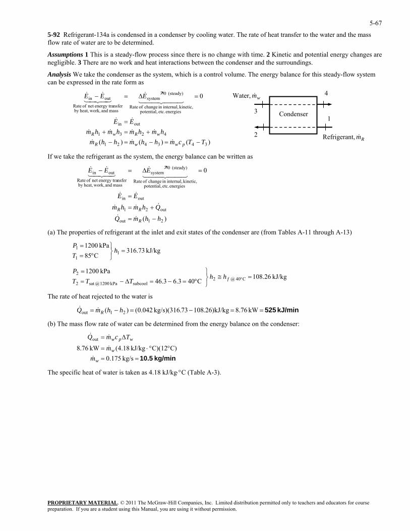
5-67
5-92 Refrigerant-134a is condensed in a condenser by cooling water. The rate of heat transfer to the water and the mass flow rate of water are to be determined.
Assumptions 1 This is a steady-flow process since there is no change with time. 2 Kinetic and potential energy changes are negligible. 3 There are no work and heat interactions between the condenser and the surroundings.
Analysis We take the condenser as the system, which is a control volume. The energy balance for this steady-flow system can be expressed in the rate form as
PROPRIETARY MATERIAL. © 2011 The McGraw-Hill Companies, Inc. Limited distribution permitted only to teachers and educators for course
(steady) 0systemoutin
TTcmhhmhhmhmhmhmhm
EE
EEE
pwwR
wRwR
−=−=−+=+
=
=∆=−
&&&
&&&&
&&
44 344 21&
43421&&
If we take the refrigerant as the system, the energy balance can be written as
(steady) 0systemoutin
hhmQ
Qhmhm
EE
EEE
R
RR
−=
+=
=
=∆=−
&&
&&&
&&
44 344 21&
43421&&
let and exit states of the condenser are (from Tables A-11 through A-13)
kPa 12001 =⎬⎫
hP
63.46kPa 1200
C40 @ 2subcoolkPa 1200 @sat 2
2 =≅⎭⎬⎫
°=−=∆−==
°fhhTTT
P
The rate of heat rejected to the water is
kW 8.76g
) The mass flow rate of water can be determined from the energy balance on the condenser:
The specific heat of water is taken as 4.18 kJ/kg⋅°C (Table A-3).
Refrigerant, m R&
Condenser 1
Water, mw&
3
4
2 ()()(
0
343421
4231
outin
energies etc. potential, kinetic, internal,in change of Rate
mass and work,heat,by nsferenergy tranet of Rate
)
)(
0
21out
out21
outin
energies etc. potential, kinetic, internal,in change of Rate
mass and work,heat,by nsferenergy tranet of Rate
(a) The properties of refrigerant at the in
=kJ/kg 73.316
C85 11 ⎭°=T
kJ/kg 26.108 C403.
−=−= kJ/k)26.10873kg/s)(316. 042.0()( 21out hhmQ R&& kJ/min 525==
(b
kg/min 10.5==°°⋅=
∆=
kg/s 0.175C)C)(12kJ/kg 18.4(kW 76.8
out
w
w
wpw
mm
TcmQ
&
&
&&
preparation. If you are a student using this Manual, you are using it without permission.
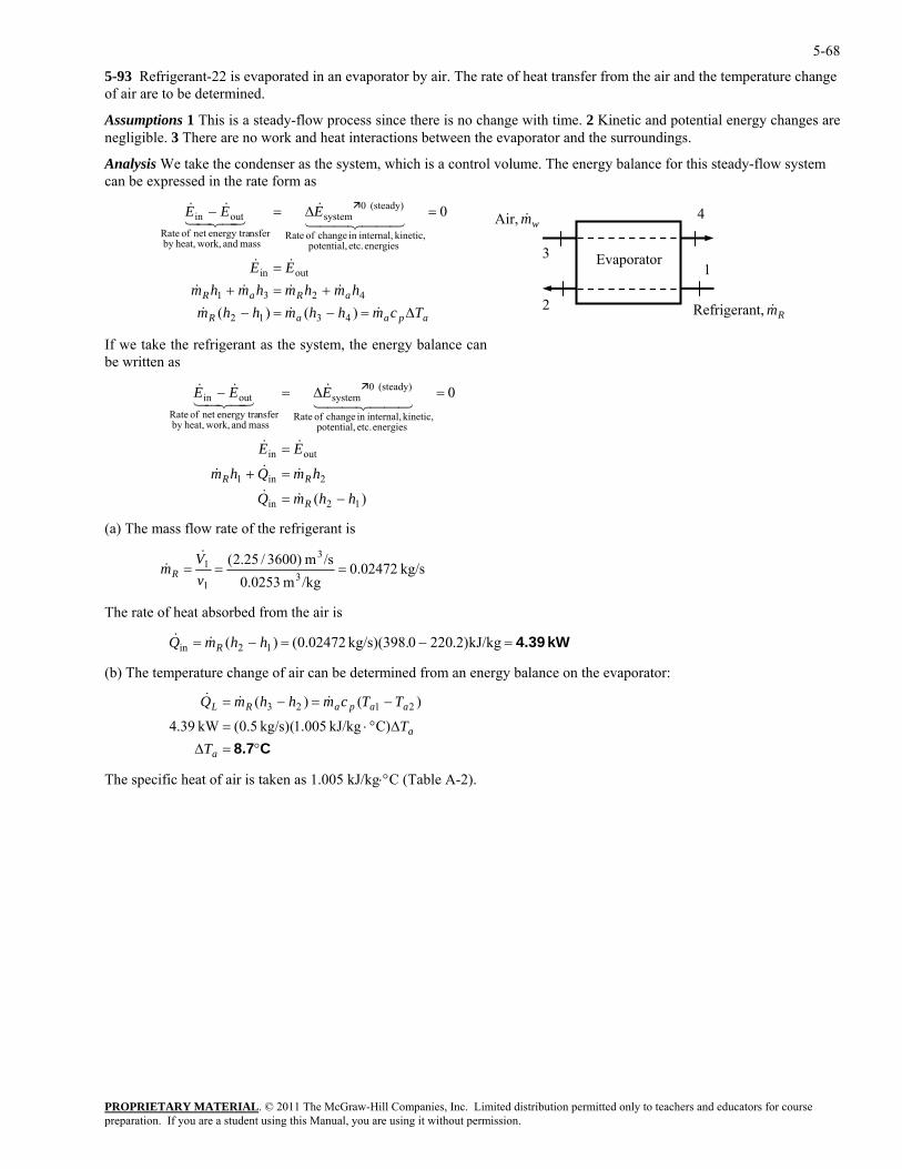
5-68
5-93 Refrigerant-22 is evaporated in an evaporator by air. The rate of heat transfer from the air and the temperature change of air are to be determined.
Assumptions 1 This is a steady-flow process since there is no change with time. 2 Kinetic and potential energy changes are negligible. 3 There are no work and heat interactions between the evaporator and the surroundings.
Analysis We take the condenser as the system, which is a control volume. The energy balance for this steady-flow system can be expressed in the rate form as
PROPRIETARY MATERIAL. © 2011 The McGraw-Hill Companies, Inc. Limited distribution permitted only to teachers and educators for course
(steady) 0systemoutin
we take the refrigerant as the system, the energy balance can be written as
outin
energies c.kinetic, internal,
(steady) 0systemoutin
hhmQ
EE
EEE
R −=
=
=∆=−
&&
&&
44 344 21&
43421&&
apaaR
aRaR
Tcmhhmhhmhmhmhmhm
EE
EEE
∆=−=−+=+
=
=∆=−
&&&
&&&&
&&
44 344 21&
43421&&
)()(
0
4312
4231
outin
Refrigerant, m R&
Evaporator 1
Air, m w&
3
4
2
energies etc. potential, kinetic, internal,in change of Rate
mass and work,heat,by nsferenergy tranet of Rate
If
)(
0
12in
et potential, in change of Rate
mass and work,heat,by nsferenergy tranet of Rate
2in1 hmQhm RR =+ &&&
(a) The mass flow rate of the refrigerant is
kg/s 02472.0/kgm 0.02531v
/sm )3600/25.2(3
31 ==
VmR
&&
he rate of heat absorbed from the air is
(b) The temperature change of air can be determined from an energy balance on the evaporator:
The specific heat of air is taken as 1.005 kJ/kg⋅°C (Table A-2).
=
T
kW 4.39=−=−= kJ/kg)2.2200kg/s)(398. 02472.0()( 12in hhmQ R&&
C8.7°=∆∆°⋅=
−=−=
a
a
aapaRL
TT
TTcmhhmQ
C)kJ/kg 005.1(kg/s) 5.0(kW 39.4
)()( 2123 &&&
preparation. If you are a student using this Manual, you are using it without permission.
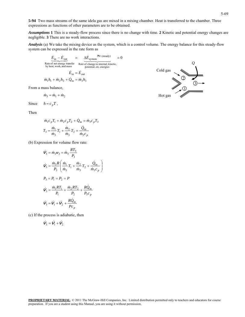
5-69
5-94 Two mass streams of the same idela gas are mixed in a mixing chamber. Heat is transferred to the chamber. Three expressions as functions of other parameters are to be obtained.
Assumptions 1 This is a steady-flow process since there is no change with time. 2 Kinetic and potential energy changes are negligible. 3 There are no work interactions.
Analysis (a) We take the mixing device as the system, which is a control volume. The energy balance for this steady-flow system can be expressed in the rate form as
33in2211
outin
energies etc. potential, kinetic, internal,in change of Rate
(steady) 0system
mass and work,heat,by nsferenergy tranet of Rate
outin 0
hmQhmhm
EE
EEE
&&&&
&&
44 344 21&
43421&&
=++
=
=∆=−
Q
PROPRIETARY MATERIAL. © 2011 The McGraw-Hill Companies, Inc. Limited distribution permitted only to teachers and educators for course
mmm && +=
Cold gas
3 1
2
Hot gas
From a mass balance,
3& 21
Since , Tch p=
Then
p
ppp
Qmmin2211
&&&
cmT
mT
mT
TcmQTcmTcm
3
in2
3
21
3
13
33
&&&
&&&
++=
=++
(b) Expression for volume flow rate:
&
⎟⎟⎠
⎞⎜⎜⎝
⎛++=
==
pcmQ
Tmm
Tmm
PRm
PRT
mm
3
in2
3
21
3
1
3
33
3
33333
&
&
&
&
&
&&&
&&&
V
vV
PPPP === 213
p
p
PcQR
cPPP 21
&
QRRTmRTm
in21
3
in22113
&&
&&&&
++=
++=
VVV
V
(c) If the process is adiabatic, then
3&
213 VVV &&& +=
preparation. If you are a student using this Manual, you are using it without permission.
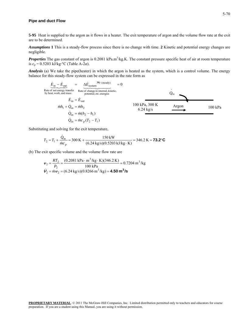
5-70
Pipe and duct Flow
5-95 Heat is supplied to the argon as it flows in a heater. The exit temperature of argon and the volume flow rate at the exit are to be determined.
Assumptions 1 This is a steady-flow process since there is no change with time. 2 Kinetic and potential energy changes are negligible.
Properties The gas constant of argon is 0.2081 kPa.m3/kg.K. The constant pressure specific heat of air at room temperature is cp = 0.5203 kJ/kg·°C (Table A-2a).
Analysis (a) We take the pipe(heater) in which the argon is heated as the system, which is a control volume. The energy balance for this steady-flow system can be expressed in the rate form as
)(
)(
0
12in
12in
2in1
outin
energies etc. potential, kinetic, internal,in change of Rate
(steady) 0system
mass and work,heat,by nsferenergy tranet of Rate
outin
TTcmQ
hhmQ
hmQhm
EE
EEE
p −=
−=
=+
=
=∆=−
&&
&&
&&&
&&
44 344 21&
43421&&
100 kPaArgon
Qin
.
100 kPa, 300 K6.24 kg/s
Substituting and solving for the exit temperature,
PROPRIETARY MATERIAL. © 2011 The McGraw-Hill Companies, Inc. Limited distribution permitted only to teachers and educators for course
C73.2°==⋅
+=+=kJ/kg 5203.0)(kg/s 24.6(
K 30012pcm
TT&
K 346.2K)
kW 150inQ&
(b) The exit specific volume and the volume flow rate are
/sm 4.50 3===
=⋅⋅
==
)/kgm 0.8266)(kg/s 24.6(
/kgm 0.7204kPa 100
)K 2.346)(K/kgmkPa 0.2081(
322
33
2
22
vV
v
mP
RT
&&
preparation. If you are a student using this Manual, you are using it without permission.
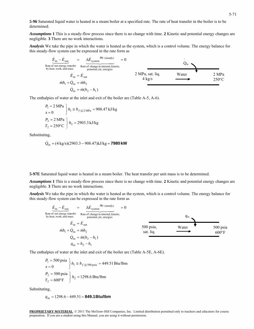
5-71
5-96 Saturated liquid water is heated in a steam boiler at a specified rate. The rate of heat transfer in the boiler is to be determined.
Assumptions 1 This is a steady-flow process since there is no change with time. 2 Kinetic and potential energy changes are negligible. 3 There are no work interactions.
Analysis We take the pipe in which the water is heated as the system, which is a control volume. The energy balance for this steady-flow system can be expressed in the rate form as
PROPRIETARY MATERIAL. © 2011 The McGraw-Hill Companies, Inc. Limited distribution permitted only to teachers and educators for course
(steady) 0systemoutin
hhmQ
hmQhm
EE
EEE
−=
=+
=
=∆=−
&&
&&&
&&
&&&
The enthalpies of water at the inlet and exit of the boiler are (Table A-5, A-6).
=⎭⎬⎫
°==
=≅⎭⎬⎫
hTP
hhx f
ubstituting,
5-97E Saturated liquid water is heated in a steam boiler. The heat transfer per unit mass is to be determined.
Assumptions 1 This is a steady-flow process since there is no change with time. 2 Kinetic and potential energy changes are negligible. 3 There are no work interactions.
alysis We take the pipe in which the water is heated as the syste a control The energy b s steady-flow system can be expressed in the rate form as
(steady) 0systemoutin
)(
0
hhqhhmQ
hmQhm
EE
EEE
−=−=
=+
=
=∆=−
&&
&&&
&&
444 344 21&
43421&&
The enthalpies of water at the inlet and exit of the boiler are (Table A-5E, A-6E).
Substituting,
2 MPa 250°C
2 MPa, sat. liq.4 kg/s
Water
Qin
.
)(
0
12in
2in1
outin
energies etc. potential, kinetic, internal,in change of Rate
mass and work,heat,by nsferenergy tranet of Rate
444 344 2143421
kJ/kg 3.2903C025
MPa 2
kJ/kg 47.9080
MPa 2
22
2
MPa 2@11
==P
S
kW 7980=−= kJ/kg)47.9083.2903)(kg/s 4(inQ
&
Anthi
m, which is volume. alance for
energies etc. potential, kinetic, internal,in change of Rate
mass and work,heat,by nsferenergy tranet of Rate
500 psia 600°F
Water 500 psia, sat. liq.
qin
12in
12in
2in1
outin
Btu/lbm 6.1298F600psia 500
Btu/lbm 51.4490
psia 500
22
2
psia 500@11
=⎭⎬⎫
°==
=≅⎭⎬⎫
==
hTP
hhxP
f
Btu/lbm 849.1=−= 51.4496.1298inq
preparation. If you are a student using this Manual, you are using it without permission.
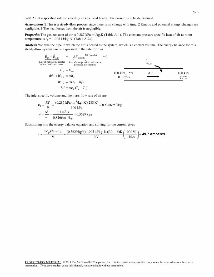
5-72
5-98 Air at a specified rate is heated by an electrical heater. The current is to be determined.
Assumptions 1 This is a steady-flow process since there is no change with time. 2 Kinetic and potential energy changes are negligible. 3 The heat losses from the air is negligible.
Properties The gas constant of air is 0.287 kPa.m3/kg.K (Table A-1). The constant pressure specific heat of air at room temperature is cp = 1.005 kJ/kg·°C (Table A-2a).
Analysis We take the pipe in which the air is heated as the system, which is a control volume. The energy balance for this steady-flow system can be expressed in the rate form as
PROPRIETARY MATERIAL. © 2011 The McGraw-Hill Companies, Inc. Limited distribution permitted only to teachers and educators for course
12ine,
2ine,1
outin
energies etc. potential,
(steady) 0systemoutin
hhmW
hmWhm
EE
EEE
−=
=+
=
=∆=−
&&
&&&
&&
&&&
he inlet s cific volume and the mass flow rate of air are
)()(
0
100 kPa 30°C
100 kPa, 15°C0.3 m3/s
Air
We,in
.kinetic, internal,in change of Rate
mass and work,heat,by nsferenergy tranet of Rate
444 344 2143421
12 TTcmI p −= &V
T pe
kg/s 3629.0/kgm 0.8266
/sm 0.3
/kgm 0.8266kPa 100
)K 288)(K/kgmkPa 0.287(
3
3
1
1
33
1
11
===
=⋅⋅
==
v
V
v
&&m
PRT
Substituting into the energy balance equation and solving for the current gives
Amperes49.7=⎟⎠⎞
⎜⎝⎛−⋅
=−
=kJ/s 1
VI 1000V 110
K)1530(K)kJ/kg 005.1)(kg/s 3629.0()( 12
VTTcm
I p&
preparation. If you are a student using this Manual, you are using it without permission.
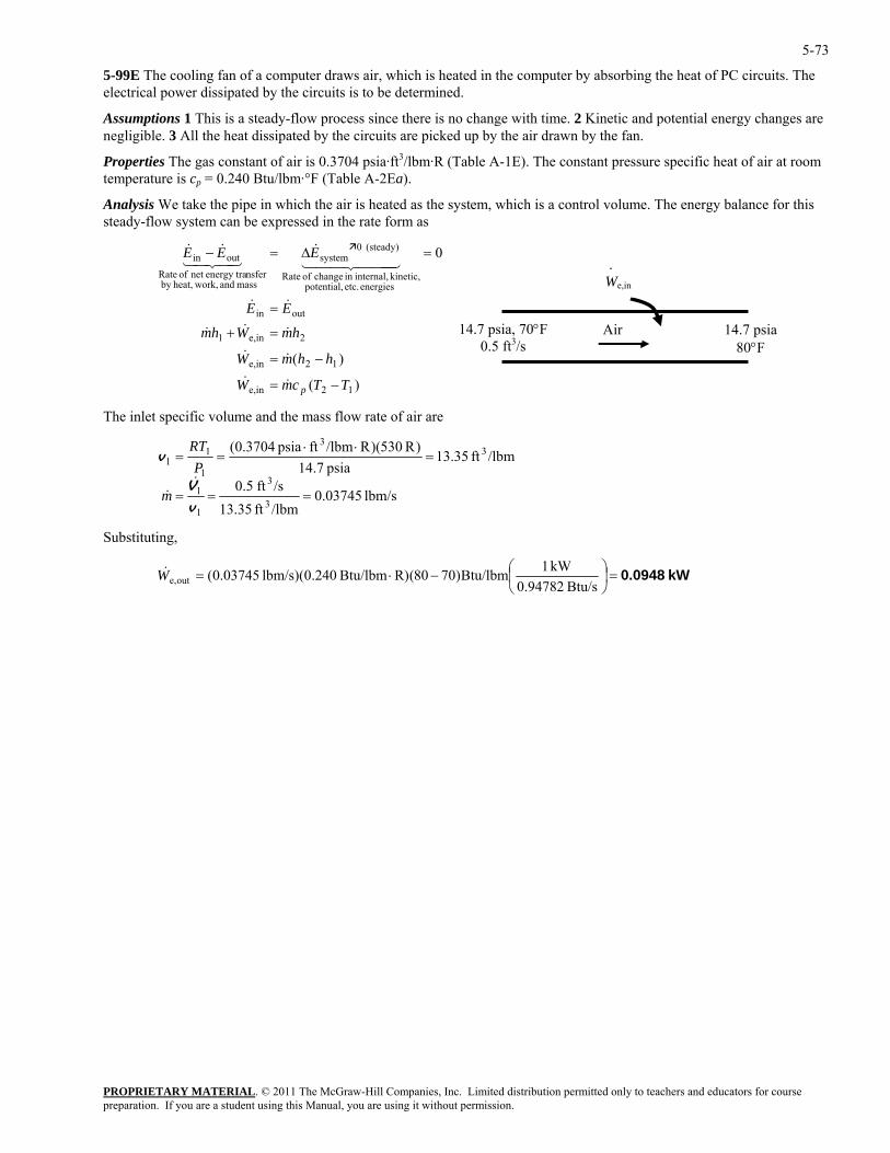
5-73
5-99E The cooling fan of a computer draws air, which is heated in the computer by absorbing the heat of PC circuits. The electrical power dissipated by the circuits is to be determined.
Assumptions 1 This is a steady-flow process since there is no change with time. 2 Kinetic and potential energy changes are negligible. 3 All the heat dissipated by the circuits are picked up by the air drawn by the fan.
Properties The gas constant of air is 0.3704 psia·ft3/lbm·R (Table A-1E). The constant pressure specific heat of air at room temperature is cp = 0.240 Btu/lbm·°F (Table A-2Ea).
Analysis We take the pipe in which the air is heated as the system, which is a control volume. The energy balance for this steady-flow system can be expressed in the rate form as
)(
)(
0
12ine,
12ine,
2ine,1
outin
energies etc. potential, kinetic, internal,in change of Rate
(steady) 0system
mass and work,heat,by nsferenergy tranet of Rate
outin
TTcmW
hhmW
hmWhm
EE
EEE
p −=
−=
=+
=
=∆=−
&&
&&
&&&
&&
444 344 21&
43421&&
14.7 psia 80°F
14.7 psia, 70°F0.5 ft3/s
Air
We,in
.
The inlet specific volume and the mass flow rate of air are
lbm/s 03745.0/lbmft 13.35/sft 0.5
/lbmft 35.13psia 14.7
)R 530)(R/lbmftpsia 0.3704(
3
3
1
1
33
1
11 =v
===
=⋅⋅
=
v
V&&m
PRT
Substituting,
kW 0.0948=⎟⎠⎞
⎜⎝⎛−⋅=
Btu/s 0.94782kW 1Btu/lbm)7080(R)Btu/lbm 240.0)(lbm/s 03745.0(oute,W&
PROPRIETARY MATERIALpreparation. If you are a student using this Manual, you are using it without permission.
. © 2011 The McGraw-Hill Companies, Inc. Limited distribution permitted only to teachers and educators for course
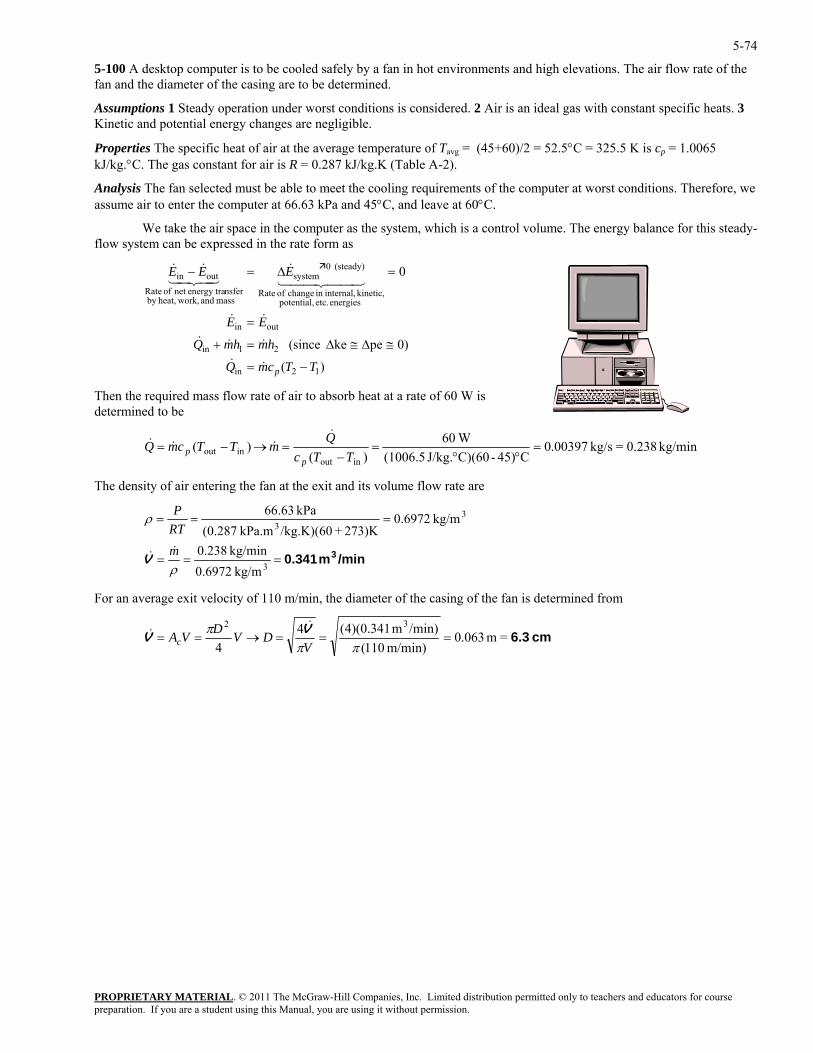
5-74
5-100 A desktop computer is to be cooled safely by a fan in hot environments and high elevations. The air flow rate of the fan and the diameter of the casing are to be determined.
Assumptions 1 Steady operation under worst conditions is considered. 2 Air is an ideal gas with constant specific heats. 3 Kinetic and potential energy changes are negligible.
Properties The specific heat of air at the average temperature of Tavg = (45+60)/2 = 52.5°C = 325.5 K is cp = 1.0065 kJ/kg.°C. The gas constant for air is R = 0.287 kJ/kg.K (Table A-2).
Analysis The fan selected must be able to meet the cooling requirements of the computer at worst conditions. Therefore, we assume air to enter the computer at 66.63 kPa and 45°C, and leave at 60°C.
We take the air space in the computer as the system, which is a control volume. The energy balance for this steady-flow system can be expressed in the rate form as
PROPRIETARY MATERIAL. © 2011 The McGraw-Hill Companies, Inc. Limited distribution permitted only to teachers and educators for course
21in
outin
(steady) 0systemoutin
TTcmQ
hmhmQ
EE
EEE
−=
≅∆≅∆=+
=
=∆=−
&&
&&&
&&
&&&
hen the r uired mass flow rate of air to absorb heat at a rate of 60 W is etermined to be
)(
0)peke (since
0
energies etc. potential, kinetic, internal,in change of Rate
mass and work,heat,by nsferenergy tranet of Rate
44 344 2143421
12in p
T eqd
kg/min 0.238=kg/s 00397.0C45)-C)(60J/kg. (1006.5
W60Q&
)( )(
inoutinout =
°°=
−=→−=
TTcmTTcmQ
pp &&&
The density of air entering the fan at the exit and its volume flow rate are
/minm 0.341 3===
===
3
33
kg/m 6972.0kg/min 238.0
kg/m 6972.0273)K+/kg.K)(60kPa.m 287.0(
kPa 63.66
ρ
ρ
mRTP
&&V
For an average exit velocity of 110 m/min, the diameter of the casing of the fan is determined from
cm 6.3=m 063.0m/min) 110(
/min)m 341.0)(4(44
32===→==
πππ
VDVDVAc
VV
&&
preparation. If you are a student using this Manual, you are using it without permission.
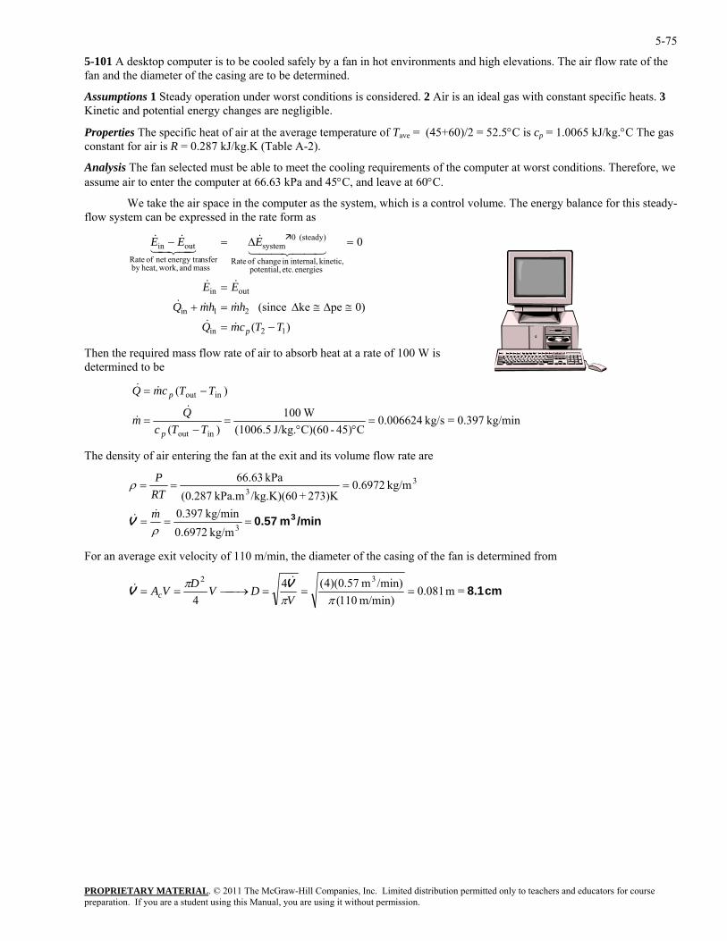
5-75
5-101 A desktop computer is to be cooled safely by a fan in hot environments and high elevations. The air flow rate of the fan and the diameter of the casing are to be determined.
Assumptions 1 Steady operation under worst conditions is considered. 2 Air is an ideal gas with constant specific heats. 3 Kinetic and potential energy changes are negligible.
Properties The specific heat of air at the average temperature of Tave = (45+60)/2 = 52.5°C is cp = 1.0065 kJ/kg.°C The gas constant for air is R = 0.287 kJ/kg.K (Table A-2).
Analysis The fan selected must be able to meet the cooling requirements of the computer at worst conditions. Therefore, we assume air to enter the computer at 66.63 kPa and 45°C, and leave at 60°C.
We take the air space in the computer as the system, which is a control volume. The energy balance for this steady-flow system can be expressed in the rate form as
PROPRIETARY MATERIAL. © 2011 The McGraw-Hill Companies, Inc. Limited distribution permitted only to teachers and educators for course
(steady) 0systemoutin
TTcmQ
hmhmQ
EE
EEE
p −=
≅∆≅∆=+
=
=∆=−
&&
&&&
&&
&&&
kinetic, internal,in change of Ratemass and work,heat,by
nsferenergy tranet of Rate44 344 2143421
)(
0)peke (since
0
12in
21in
outin
energies etc. potential,
Then the required mass flow rate of air to absorb heat at a rate of 100 W is determined to be
kg/min 0.397=kg/s 006624.0C45)-C)(60J/kg. (1006.5
W100inout
Qp
&
)(
)(
inout=
°°=
−=
−=
TTcm
TTcm
p&
&
The density of air entering the fan at the exit and its volume flow rate are
Q&
/minm 0.57 3===
===
3
33
kg/m 6972.0kg/min 397.0
kg/m 6972.0273)K+/kg.K)(60kPa.m 287.0(
kPa 63.66
ρ
ρ
mRTP
&&V
For an average exit velocity of 110 m/min, the diameter of the casing of the fan is determined from
cm 8.1=m 081.0m/min) 110(
/min)m 57.0)(4(44
32===⎯→⎯==
πππ
VDVDVAc
VV
&&
preparation. If you are a student using this Manual, you are using it without permission.
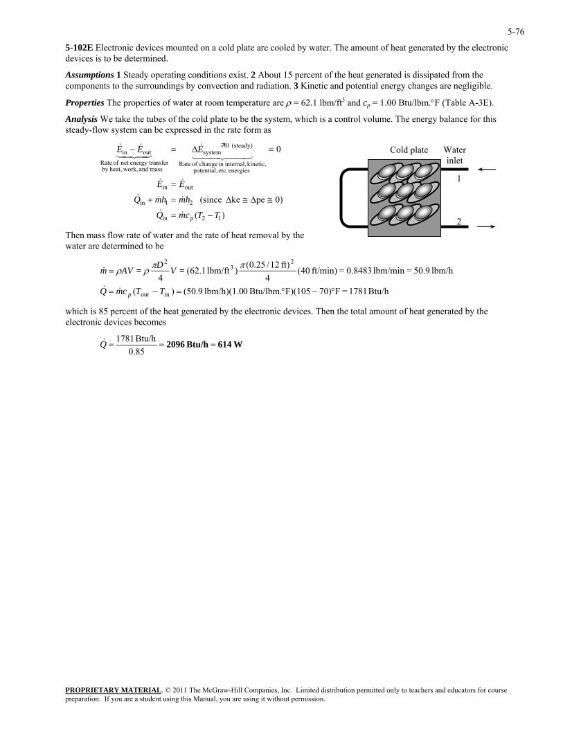
5-76
5-102E Electronic devices mounted on a cold plate are cooled by water. The amount of heat generated by the electronic devices is to be determined.
Assumptions 1 Steady operating conditions exist. 2 About 15 percent of the heat generated is dissipated from the components to the surroundings by convection and radiation. 3 Kinetic and potential energy changes are negligible.
Properties The properties of water at room temperature are ρ = 62.1 lbm/ft3 and cp = 1.00 Btu/lbm.°F (Table A-3E).
Analysis We take the tubes of the cold plate to be the system, which is a control volume. The energy balance for this steady-flow system can be expressed in the rate form as
PROPRIETARY MATERIAL. © 2011 The McGraw-Hill Companies, Inc. Limited distribution permitted only to teachers and educators for course
(steady) 0systemoutin
TTcmQ
hmhmQ
EE
EEE
p −=
≅∆≅∆=+
=
=∆=−
&&
&&&
&&
&&&
)(
0)peke (since
0
12in
21in
outin
energies etc. potential, 1 2
Water inlet
Cold plate kinetic, internal,in change of Rate
mass and work,heat,by nsferenergy tranet of Rate
44 344 2143421
Then mass flow rate of water and the rate of heat removal by the water are determined to be
Btu/h 1781=F70)F)(105Btu/lbm. 0lbm/h)(1.0 9.50()(
lbm/h 50.9=lbm/min 0.8483=ft/min) 40(4
ft) 12/25.0()lbm/ft 1.62(4
inout
23
2
°−°=−=
=&
TTcmQ
VDAVm
p&&
ππρρ ==
which is 85 percent of the heat generated by the electronic devices. Then the total amount of heat generated by the electronic devices becomes
W614Btu/h 2096 ===0.85
Btu/h 1781Q&
preparation. If you are a student using this Manual, you are using it without permission.
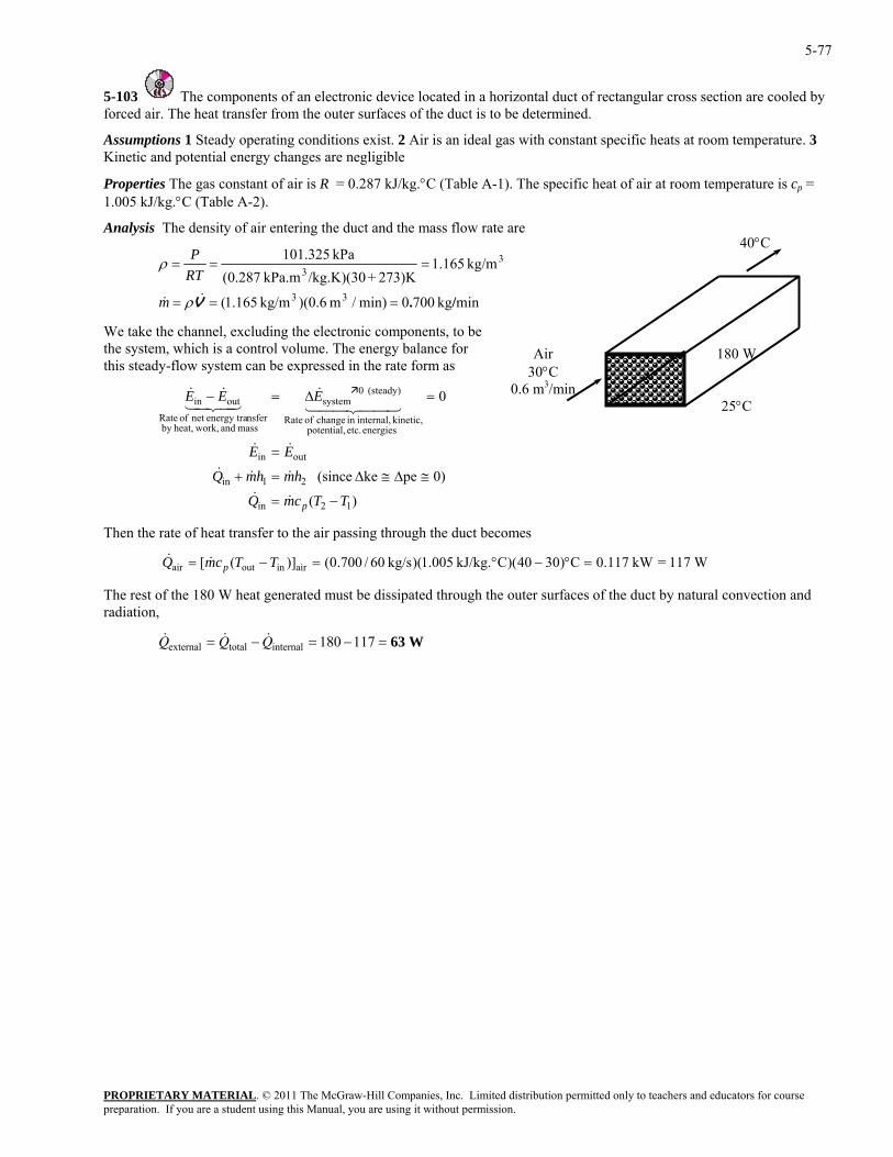
5-77
5-103 The components of an electronic device located in a horizontal duct of rectangular cross section are cooled by forced air. The heat transfer from the outer surfaces of the duct is to be determined.
Assumptions 1 Steady operating conditions exist. 2 Air is an ideal gas with constant specific heats at room temperature. 3 Kinetic and potential energy changes are negligible
Properties The gas constant of air is R = 0.287 kJ/kg.°C (Table A-1). The specific heat of air at room temperature is cp = 1.005 kJ/kg.°C (Table A-2).
Analysis The density of air entering the duct and the mass flow rate are
PROPRIETARY MATERIAL. © 2011 The McGraw-Hill Companies, Inc. Limited distribution permitted only to teachers and educators for course
minkg7000min)/m 6.0)(kg/m 165.1(
273)K+/kg.K)(30kPa.m 287.0(33
3
/ .=== V&& ρm
RTkg/m 165.1kPa 325.101
==P
We take the channel, excluding the electronic components, to be the system, which is a control volume. The energy balance for this steady-flow system can be expressed in the rate form as
0
12in
outin
energies etc. potential, kinetic, internal,in change of Rate
(steady) 0system
mass and work,heat,by nsferenergy tranet of Rate
outin
TTcmQ
EE
EEE
p −=
=
=∆=−
&&
&&
44 344 21&
43421&&
The rest of the 180 W heat generated must be dissipated through the outer surfaces of the duct by natural convection and diation,
40°C
180 W
25°C
Air 30°C
0.6 m3/min
=ρ 3
0)peke (since 21in hmhmQ ≅∆≅∆=+ &&&
)(
Then the rate of heat transfer to the air passing through the duct becomes
& W117=kW 117.0C)3040)(CkJ/kg. 005.1)(kg/s 60/700.0()]([ airinoutair =°−°=−= TTcmQ p&
ra
& & &Q Q Qexternal total internal= − = − =180 117 63 W
preparation. If you are a student using this Manual, you are using it without permission.
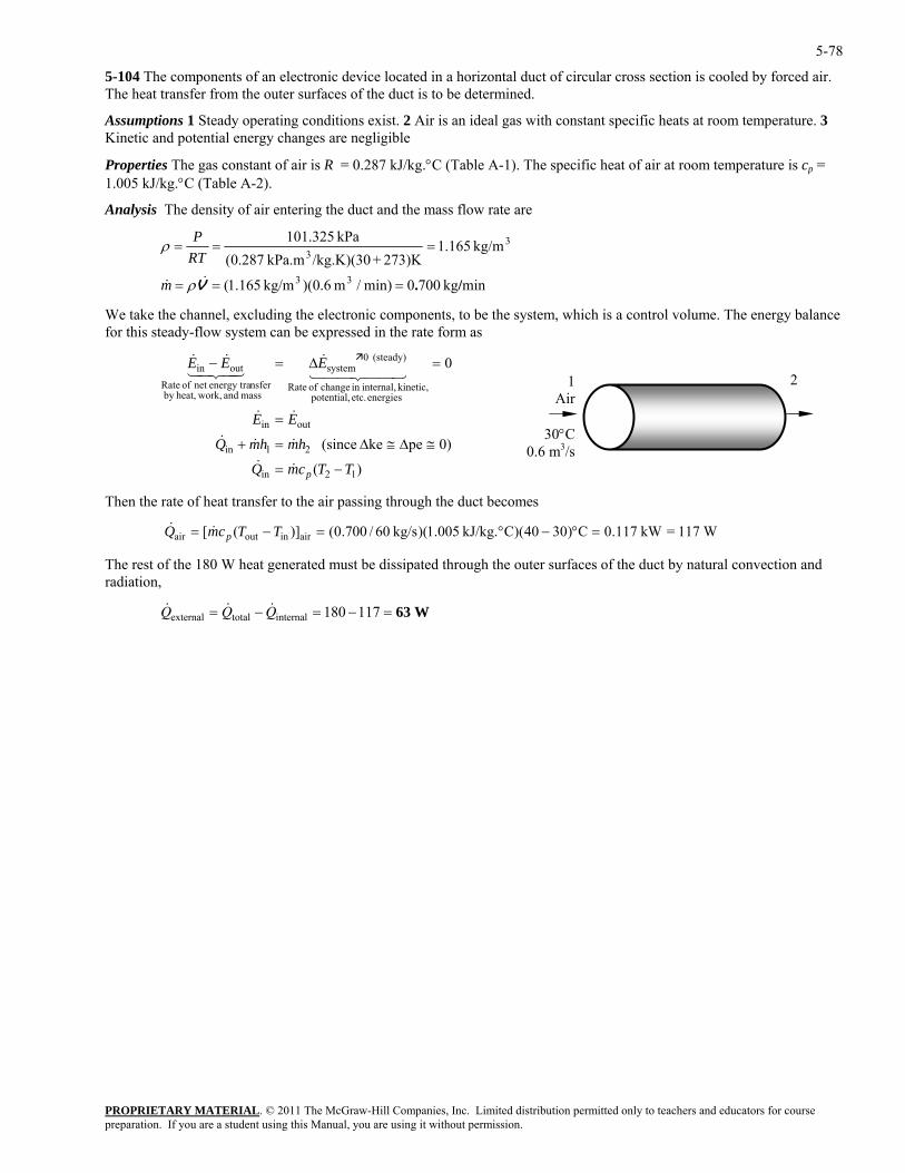
5-78
5-104 The components of an electronic device located in a horizontal duct of circular cross section is cooled by forced air. The heat transfer from the outer surfaces of the duct is to be determined.
Assumptions 1 Steady operating conditions exist. 2 Air is an ideal gas with constant specific heats at room temperature. 3 Kinetic and potential energy changes are negligible
Properties The gas constant of air is R = 0.287 kJ/kg.°C (Table A-1). The specific heat of air at room temperature is cp = 1.005 kJ/kg.°C (Table A-2).
Analysis The density of air entering the duct and the mass flow rate are
PROPRIETARY MATERIAL. © 2011 The McGraw-Hill Companies, Inc. Limited distribution permitted only to teachers and educators for course
minkg7000min)/m 6.0)(kg/m 165.1(
273)K+/kg.K)(30kPa.m 287.0(33
3
/ .=== V&& ρm
RT kg/m 165.1kPa 325.101 3==
P
We take the channel, excluding the electronic components, to be the system, which is a control volume. The energyfor this steady-flow system can be expressed in the rate form as
0
12in
outin
energies etc. potential, kinetic, internal,in change of Rate
(steady) 0system
mass and work,heat,by nsferenergy tranet of Rate
outin
TTcmQ
EE
EEE
p −=
=
=∆=−
&&
&&
44 344 21&
43421&&
p&
The rest of the 180 W heat generated must be dissipated through the outer surfaces of the duct by natural convection and diation,
=ρ
balance
)(
0)peke (since 21in hmhmQ ≅∆≅∆=+ &&&
Then the rate of heat transfer to the air passing through the duct becomes
Q& W117=kW 117.0C)3040)(CkJ/kg. 005.1)(kg/s 60/700.0()]([ airinoutair =°−°=−= TTcm
ra
& & &Q Q Qexternal total internal= − = − =180 117 63 W
2 1Air
30°C3/s0.6 m
preparation. If you are a student using this Manual, you are using it without permission.
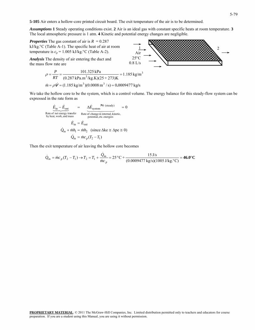
5-79
5-105 Air enters a hollow-core printed circuit board. The exit temperature of the air is to be determined.
Assumptions 1 Steady operating conditions exist. 2 Air is an ideal gas with constant specific heats at room temperature. 3 The local atmospheric pressure is 1 atm. 4 Kinetic and potential energy changes are negligible.
Properties The gas constant of air is R = 0.287 kJ/kg.°C (Table A-1). The specific heat of air at room temperature is cp = 1.005 kJ/kg.°C (Table A-2).
Analysis The density of air entering the duct and the mass flow rate are
PROPRIETARY MATERIAL. © 2011 The McGraw-Hill Companies, Inc. Limited distribution permitted only to teachers and educators for course
skg 00094770)s/m 0008.0)(kg/m 185.1(
273)K+/kg.K)(25kPa.m 287.0( 3
== V&& ρm
RT kg/m 185.1kPa 325.101
33 /.=
==P
We take the hollow core to be the system, which is a control volume. The energy balance for this steady-flow system can be expressed in the rate form as
0
12in
outin
energies etc. potential, kinetic, internal,in change of Rate
(steady) 0system
mass and work,heat,by nsferenergy tranet of Rate
outin
TTcmQ
EE
EEE
p −=
=
=∆=−
&&
&&
44 344 21&
43421&&
hen the exit temperature of air leaving the hollow core becomes
=ρ 3
0)peke (since 21in hmhmQ ≅∆≅∆=+ &&&
)(
T
C46.0°=°
°=+=→−=C)J/kg. kg/s)(1005 0009477.0(
J/s 15+C 25)( in1212in
pp cm
QTTTTcmQ
&
&&&
2 1Air
25°C0.8 L/s
preparation. If you are a student using this Manual, you are using it without permission.
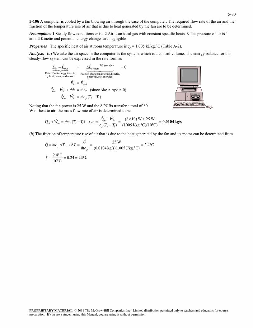
5-80
5-106 A computer is cooled by a fan blowing air through the case of the computer. The required flow rate of the air and the fraction of the temperature rise of air that is due to heat generated by the fan are to be determined.
Assumptions 1 Steady flow conditions exist. 2 Air is an ideal gas with constant specific heats. 3 The pressure of air is 1 atm. 4 Kinetic and potential energy changes are negligible
Properties The specific heat of air at room temperature is cp = 1.005 kJ/kg.°C (Table A-2).
Analysis (a) We take the air space in the computer as the system, which is a control volume. The energy balance for this steady-flow system can be expressed in the rate form as
)(
0)peke (since
0
12inin
21inin
outin
energies etc. potential, kinetic, internal,in change of Rate
(steady) 0system
mass and work,heat,by nsferenergy tranet of Rate
outin
TTcmWQ
hmhmWQ
EE
EEE
p −=+
≅∆≅∆=++
=
=∆=−
&&&
&&&&
&&
44 344 21&
43421&&
Noting that the fan power is 25 W and the 8 PCBs transfer a total of 80 W of heat to air, the mass flow rate of air is determined to be
PROPRIETARY MATERIAL. © 2011 The McGraw-Hill Companies, Inc. Limited distribution permitted only to teachers and educators for course
kg/s 0.0104=°°
=−
=→−=+C)C)(10J/kg. (1005)(
)(ininiep
iep TTcmTTcmWQ &&
+×+ W25 W10)(8inin WQ &&&
(b) The fraction of temperature rise of air that is due to the heat generated by the fan and its motor can be determined from
&
24%==°°
°=°
==∆→∆=
24.0C10C2.4=
C4.2C)J/kg. kg/s)(1005 (0.0104
W25
f
cmQ
TTcmQp
p &
&&&
preparation. If you are a student using this Manual, you are using it without permission.
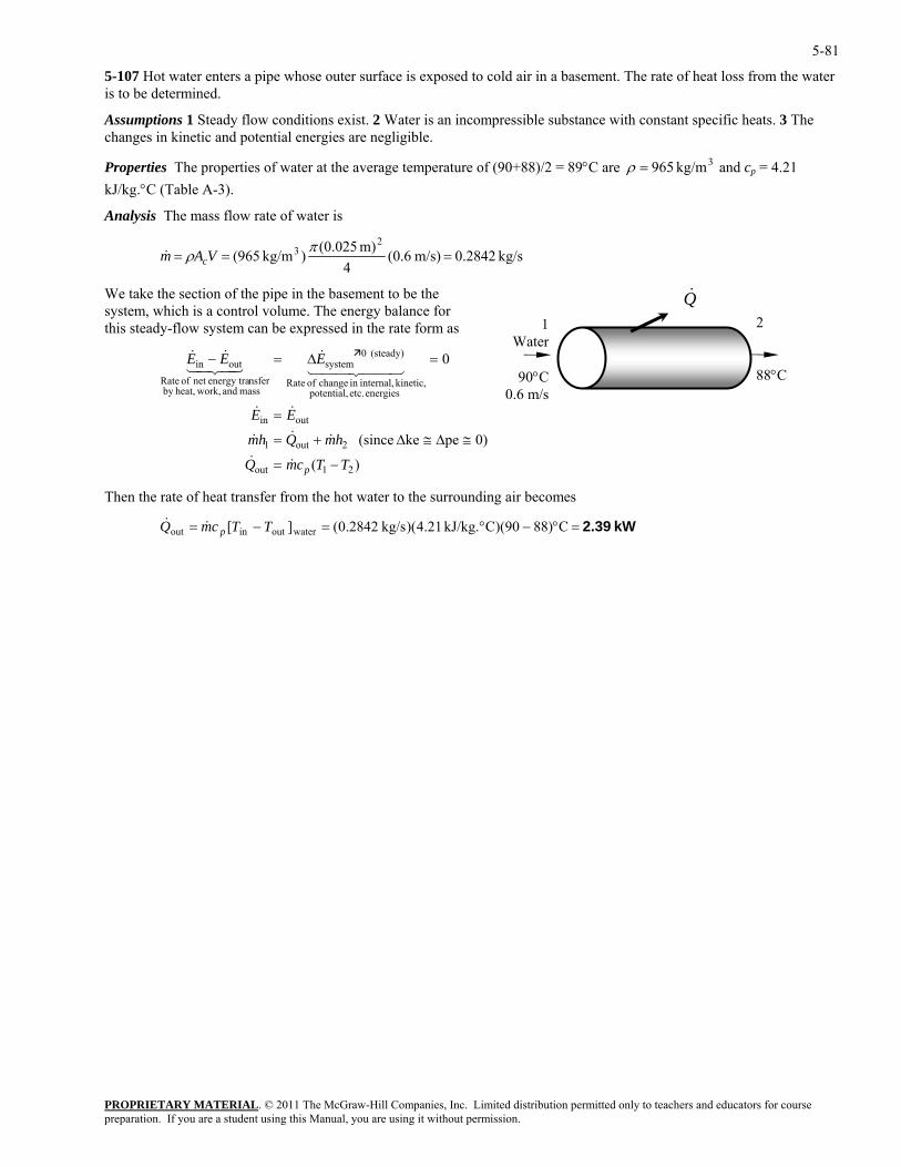
5-81
5-107 Hot water enters a pipe whose outer surface is exposed to cold air in a basement. The rate of heat loss from the water is to be determined.
Assumptions 1 Steady flow conditions exist. 2 Water is an incompressible substance with constant specific heats. 3 The changes in kinetic and potential energies are negligible.
PROPRIETARY MATERIAL. © 2011 The McGraw-Hill Companies, Inc. Limited distribution permitted only to teachers and educators for course
A-3). Properties The properties of water at the average temperature of (90+88)/2 = 89°C are 3kg/m 965=ρ and cp = 4.21 kJ/kg.°C (Table
Analysis The mass flow rate of water is
kg/s 0.2842m/s)6.0(4
m) (0.025)kg/m 965(2
3 === πρ VAm c&
We take the section of the pipe in the basement to be the system, which is a control volume. The energy balance for this steady-flow system can be expressed in the rate form as
)(
0)peke (since
0
21out
2out1
outin
energies etc. potential, kinetic, internal,in change of Rate
systemnsferenergy tranet of Rate
outin EEE =∆=−44 344 2143421
(steady) 0
mass and work,heat,by
TTcmQ
hmQhm
EE
p −=
≅∆≅∆+=
=
&&
&&&
&&
&&&
Then the rate of heat transfer from the hot water to the surrounding air becomes
Q& 2 88°C
1Water
90°C0.6 m/s
kW 2.39=°−°=−= C)8890)(CkJ/kg. 21.4)(kg/s 2842.0(][ wateroutinout TTcmQ p&&
preparation. If you are a student using this Manual, you are using it without permission.
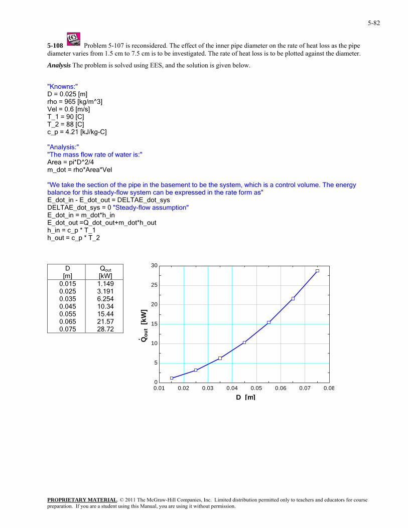
5-82
5-108 Problem 5-107 is reconsidered. The effect of the inner pipe diameter on the rate of heat loss as the pipe ss is to be plotted against the diameter.
nalysis The problem is solved using EES, and the solution is given below.
^3] ]
[kJ/kg-C]
water is:"
a control volume. The energy sed in the rate form as"
sumption"
_out+m_dot*h_out
_out = c_p * T_2
diameter varies from 1.5 cm to 7.5 cm is to be investigated. The rate of heat lo
A
"Knowns:" D = 0.025 [m]
/mrho = 965 [kgVel = 0.6 [m/sT_1 = 90 [C]
_2 = 88 [C] Tc_p = 4.21 "Analysis:" "The mass flow rate of
e = pi*D^2/4 Ar am_dot = rho*Area*Vel
ment to be the system, which is"We take the section of the pipe in the basebalance for this steady-flow system can be expresE_dot_in - E_dot_out = DELTAE_dot_sys DELTAE_dot_sys = 0 "Steady-flow as
t*h_in E_dot_in = m_doE_dot_out =Q_dot
_in = c_p * T_1 hh
0.01 0.02 0.03 0.04 0.05 0.06 0.07 0.080
5
10
15
20
25
30D [m]
Q out
[kW] 0.015 0.025 0.035 0.045 0.055 0.065 0.075 28.72
1.149 3.191 6.254 10.34 15.44 21.57
Qou
t [k
W]
D [m]
PROPRIETARY MATERIALpreparation. If you are a student using this Manual, you are using it without permission.
. © 2011 The McGraw-Hill Companies, Inc. Limited distribution permitted only to teachers and educators for course
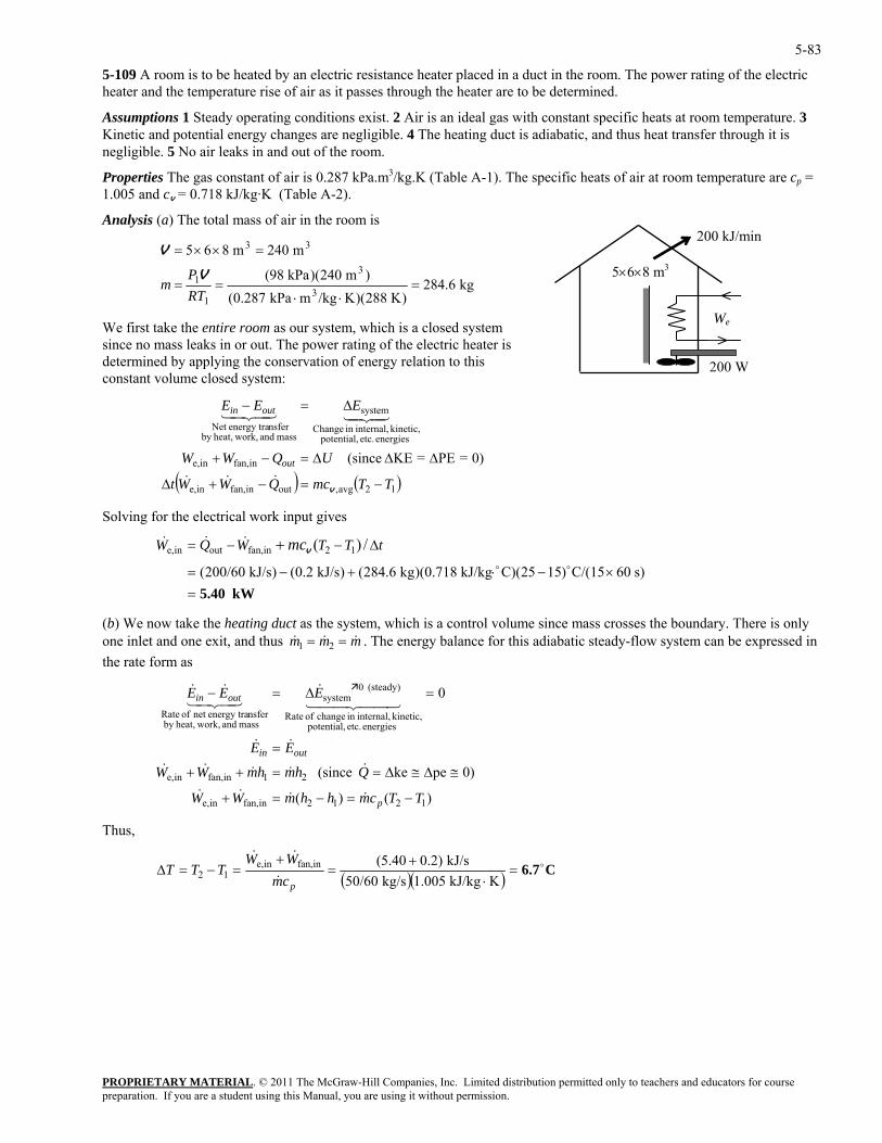
5-83
5-109 A room is to be heated by an electric resistance heater placed in a duct in the room. The power rating of the electric heater and the temperature rise of air as it passes through the heater are to be determined.
Assumptions 1 Steady operating conditions exist. 2 Air is an ideal gas with constant specific heats at room temperature. 3 Kinetic and potential energy changes are negligible. 4 The heating duct is adiabatic, and thus heat transfer through it is negligible. 5 No air leaks in and out of the room.
Properties The gas constant of air is 0.287 kPa.m3/kg.K (Table A-1). The specific heats of air at room temperature are cp = 1.005 and cv = 0.718 kJ/kg·K (Table A-2).
Analysis (a) The total mass of air in the room is
5×6×8 m3
We
200 W
200 kJ/min
kg 284.6
)K 288)(K/kgmkPa 0.287()m 240)(kPa 98(
m 240m 865
3
3
1
1
33
=⋅⋅
==
=××=
RTP
mV
V
We first take the entire room as our system, which is a closed system since no mass leaks in or out. The power rating of the electric heater is determined by applying the conservation of energy relation to this constant volume closed system:
( ) ( )12avg,outinfan,ine,
infan,ine,
energies etc. potential, internal,in Change
mass and work,heat,by nsferenergy traNet
421kinetic,
system
0)=PE=KE (since
TTmcQWWt
UQWW
EEE
out
outin
−=−+∆
∆∆∆=−+
∆=−
v&&&
4343421
Solving for the electrical work input gives
s) 60C/(15)1525)(CkJ/kg 0.718)(kg 284.6()kJ/s 0.2()kJ/s 200/60( oo
(b) We now take the heating duct as the system, which is a control volume since mass crosses the boundary. There is only & . The energy balance for this adiabatic steady-flow system can be expressed in
e rate form as
&&
44 344 21&
43421&&
Thus,
∆−−= + /)( 12infan,outine,&&& tTTWQW mcv
kW 5.40=×−⋅+−=
& &m m m1 2= =one inlet and one exit, and thus th
)()(
0)peke (since
0
1212infan,ine,
21infan,ine,
energies etc. potential, kinetic, internal,in change of Rate
(steady) 0system
mass and work,heat,by nsferenergy tranet of Rate
TTcmhhmWW
QhmhmWW
EE
EEE
p
outin
outin
−=−=+
≅∆≅∆==++
=
=∆=−
&&&&
&&&&
&
( )( ) C6.7o&
&&=
⋅+
=+
=−=∆KkJ/kg 1.005kg/s 50/60
kJ/s )2.040.5(infan,ine,12
pcmWW
TTT
PROPRIETARY MATERIALpreparation. If you are a student using this Manual, you are using it without permission.
. © 2011 The McGraw-Hill Companies, Inc. Limited distribution permitted only to teachers and educators for course
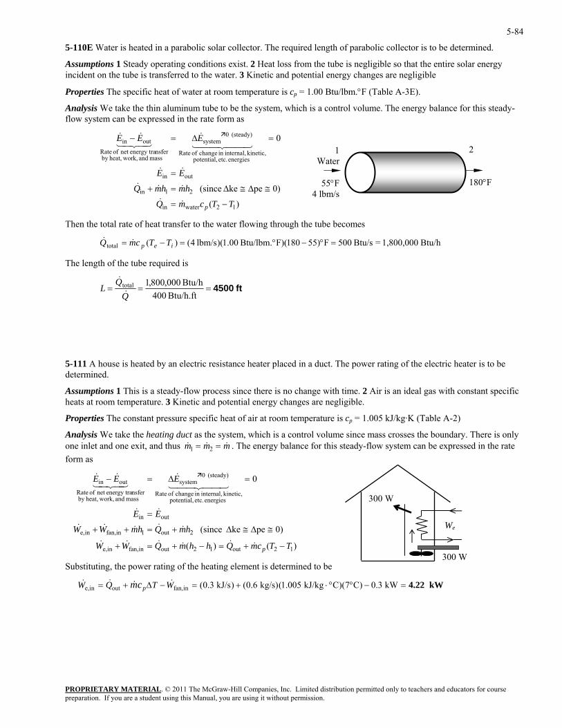
5-84
5-110E Water is heated in a parabolic solar collector. The required length of parabolic collector is to be determined.
Assumptions 1 Steady operating conditions exist. 2 Heat loss from the tube is negligible so that the entire solar energy incident on the tube is transferred to the water. 3 Kinetic and potential energy changes are negligible
Properties The specific heat of water at room temperature is cp = 1.00 Btu/lbm.°F (Table A-3E).
Analysis We take the thin aluminum tube to be the system, which is a control volume. The energy balance for this steady-flow system can be expressed in the rate form as
)(
0)peke (since
0
12waterin
21in
outin
energies etc. potential, kinetic, internal,in change of Rate
(steady) 0system
mass and work,heat,by nsferenergy tranet of Rate
outin
TTcmQ
hmhmQ
EE
EEE
p −=
≅∆≅∆=+
=
=∆=−
&&
&&&
&&
44 344 21&
43421&&
2 180°F
1Water
55°F4 lbm/s
Then the total rate of heat transfer to the water flowing through the tube becomes
PROPRIETARY MATERIAL. © 2011 The McGraw-Hill Companies, Inc. Limited distribution permitted only to teachers and educators for course
=°−°=−= iep TTcmQ & Btu/h 1,800,000=Btu/s 500F)55180)(FBtu/lbm. 00.1)(lbm/s 4()(total&
The length of the tube required is
ft 4500===Btu/h.ft 400
Btu/h 000,800,1total
L&
&
5-111 A house is heated by an electric resistance heater placed in a duct. The power rating of the electric heater is to be determined.
Assumptions 1 This is a steady-flow process since there is no change with time. 2 Air is an ideal gas with constant specific heats at room temperature. 3 Kinetic and potential energy changes are negligible.
Properties The constant pressure specific heat of air at room temperature is c = 1.005 kJ/kg·K (Table A-2) p
Analysis We take the heating duct as the system, which is a control volume since mass crosses the boundary. There is only one inlet and one exit, and thus &m= = . The energy balance for this steady-flow system can be expressed in the rate & &m m1 2
form as
2out1infan,ine,
outin
energies etc. potential, kinetic, internal,in change of Rate
(steady) 0system
mass and work,heat,by nsferenergy tranet of Rate
outin
hmQhmWW
EE
EEE
≅∆≅∆+=++
=
=∆=−
&&&&&
&&
44 344 21&
43421&&
s tuting, the power rating of the heating element is determined to be
We
300 W
300 W
0)peke (since
0
)()( 12out12outinfan,ine, TTcmQhhmQWW p −+=−+=+ &&&&&&
Sub ti
kW 4.22=−°°⋅+=−∆+= kW 0.3)C7)(CkJ/kg 1.005(kg/s) 0.6()kJ/s 0.3(infan,outine, WTQW pcm &&& &
preparation. If you are a student using this Manual, you are using it without permission.
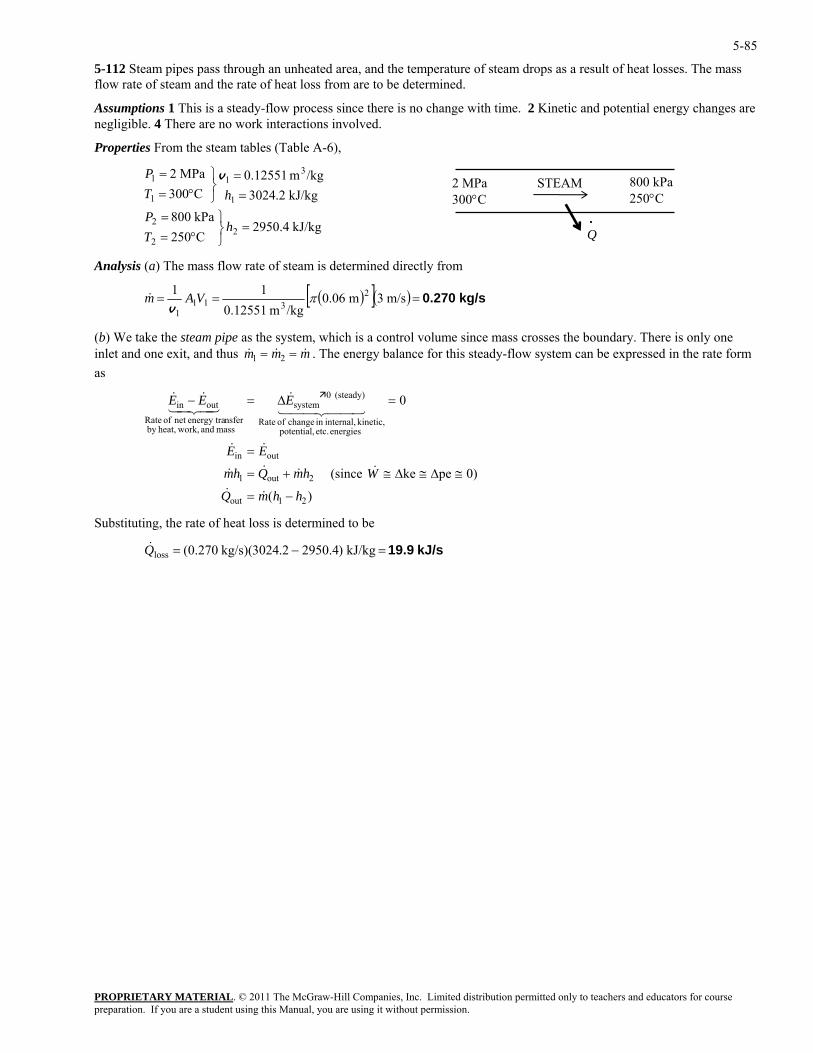
5-85
5-112 Steam pipes pass through an unheated area, and the temperature of steam drops as a result of heat losses. The mass flow rate of steam and the rate of heat loss from are to be determined.
Assumptions 1 This is a steady-flow process since there is no change with time. 2 Kinetic and potential energy changes are negligible. 4 There are no work interactions involved.
Properties From the steam tables (Table A-6),
kJ/kg 2950.4
C250kPa 800
kJ/kg .23024/kgm 0.12551
C300MPa 2
22
2
1
31
1
1
=⎭⎬⎫
°==
==
⎭⎬⎫
°==
hTP
hTP v 2 MPa
300°C STEAM 800 kPa
250°C
Q ·
Analysis (a) The mass flow rate of steam is determined directly from
( )[ ]( ) kg/s 0.270===& m/s 3m 0.0611 2πVAm
stemt and one exit, and thus . The energy balance for this steady-flow system can be expressed in the rate form
s
mass and work,heat,by nsferenergy tranet of Rate
hhmQ
WhmQhm
EE
−=
≅∆≅∆≅+=
=
=
&&
&&&&
&&
44 344 21
/kgm 0.12551 3111v
(b) We take the steam pipe as the sy , which is a control volume since mass crosses the boundary. There is only one inle & & &m m m1 2= =a
)(
0)peke (since
0
21out
2out1
outin
energies etc. potential, kinetic, internal,in change of Rate
(steady) 0systemoutin EEE ∆=− &
43421
Substituting, the rate of heat loss is determined to be
&&
kJ/s 19.9=−= kJ/kg )2950.4.23024)(kg/s 0.270(lossQ&
PROPRIETARY MATERIALpreparation. If you are a student using this Manual, you are using it without permission.
. © 2011 The McGraw-Hill Companies, Inc. Limited distribution permitted only to teachers and educators for course
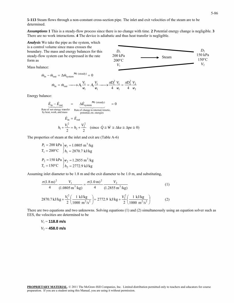
5-86
5-113 Steam flows through a non-constant cross-section pipe. The inlet and exit velocities of the steam are to be determined.
Assumptions 1 This is a steady-flow process since there is no change with time. 2 Potential energy change is negligible. 3 There are no work interactions. 4 The device is adiabatic and thus heat transfer is negligible.
Analysis We take the pipe as the system, which is a control volume since mass crosses the boundary. The mass and energy balances for this steady-flow system can be expressed in the rate form as
PROPRIETARY MATERIAL. © 2011 The McGraw-Hill Companies, Inc. Limited distribution permitted only to teachers and educators for course
Mass balance:
2
222
1
121
1
11
1
11outin
(steady) 0systemoutin
44
0
vvvvVDVDVAVAmm
mmm
ππ=⎯→⎯=⎯→⎯=
=∆=−
&&
&&&
Energy balance:
D1200 kPa 200°C
V1
Steam
D2150 kPa 150°C
V2
0)peke (since 22
0
22outin
VV 22
11
energies etc. potential, kinetic, internal,in change of Rate
(steady) 0system
mass and work,heat,by nsferenergy tranet of Rate
outin
≅∆≅∆≅≅+=+
=
=∆=−
WQhh
EE
EEE
&&
&&
44 344 21&
43421&&
he properties of steam at the inlet and exit are (Table A-6)
kPa 002 311 =⎫=P v
C150 2
2
1
2
=⎭⎬°= hT
P
Assuming inlet diameter to be 1.8 m and the exit diameter to be 1.0 m, and substituting,
T
kJ/kg 7.2870C200 11 =⎭
⎬°= hT /kgm 0805.1
/kgm 2855.1kPa 015 3=⎫= v
kJ/kg 9.2772
)/kgm 1.2855(4
)m 1.0()m 1.8( 2
31
2 VV ππ=
)/kgm 5 32 (1)
1.080(4
⎟⎠⎞
⎜⎝⎛+=⎟
⎠⎞
⎜⎝⎛+ 1kJ/kg 2870.7 V
22
22
22
2
/sm 1000kJ/kg 1
2kJ/kg 2772.9
/sm 1000kJ/kg 1
2V
(2)
There are two equations and two unknowns. Solving equations (1) and (2) simultaneously using an equation solver such as EES, the velocities are determined to be
V1 = 118.8 m/s
V2 = 458.0 m/s
preparation. If you are a student using this Manual, you are using it without permission.
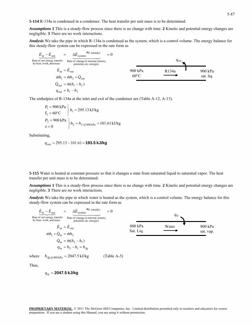
5-87
5-114 R-134a is condensed in a condenser. The heat transfer per unit mass is to be determined.
Assumptions 1 This is a steady-flow process since there is no change with time. 2 Kinetic and potential energy changes are negligible. 3 There are no work interactions.
Analysis We take the pipe in which R-134a is condensed as the system, which is a control volume. The energy balance for this steady-flow system can be expressed in the rate form as
PROPRIETARY MATERIAL. © 2011 The McGraw-Hill Companies, Inc. Limited distribution permitted only to teachers and educators for course
(steady) 0systemoutin
)(
0
hhqhhmQ
Qhmhm
EE
EEE
−=−=
+=
=
=∆=−
&&
&&&
&&
&&&
of R-134a at the inlet and exit of the condenser are (Table A-12, A-13).
5-115 Water is heated at constant pressure so that it changes a state from saturated liqui o saturated vapor. The heat transfer per unit mass is to be determined.
Assumptions 1 This is a steady-flow process since there is no change with time. 2 c and potentia anges are egligible. 3 There are no work interactions.
lysis We take the pipe in which water is heated e system, which is a control volume. The energy balance for this steady-flow system can be expressed in the rate form as
ernal,
(steady) 0
mass and work,enet
in
)(
0
&&
&&&
&&
443&
42&&
where (Table A-5)
Thus,
21out
21out
out21
outin
energies etc. potential, kinetic, internal,in change of Rate
mass and work,heat,by nsferenergy tranet of Rate
444 344 2143421
900 kPa sat. liq.
qout
900 kPa 60°C
R134a
The enthalpies
kJ/kg 61.1010
kPa 900
kJ/kg 13.295C60kPa 900
kPa 900@22
11
1
==⎭⎬⎫
==
=⎭⎬⎫
°==
fhhxP
hTP
Substituting,
kJ/kg 193.5=−= 61.10113.295outq
d t
Kineti l energy chn
Ana as th
fghhhqhhmQ
hmQhm
EE
EEE
=−=−=
=+
=
=∆=−
12in
12in
2in1
outin
energies etc. potential, kinetic, intin change of Rate
systemnsfernergy tra of Rate
out 444 21431
800 kPa sat. vap.
Water800 kPa Sat. Liq.
qin
heat,by
kJ/kg 5.2047kPa 800@ =fgh
kJ/kg 2047.5=inq
preparation. If you are a student using this Manual, you are using it without permission.
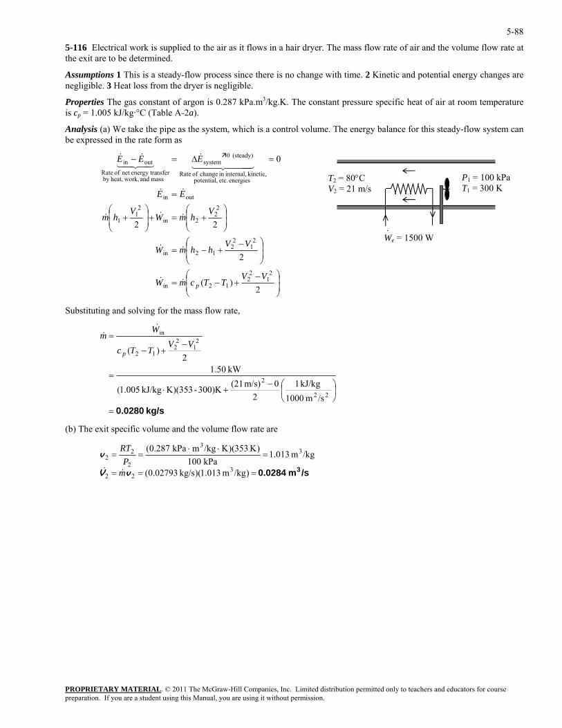
5-88
5-116 Electrical work is supplied to the air as it flows in a hair dryer. The mass flow rate of air and the volume flow rate at the exit are to be determined.
Assumptions 1 This is a steady-flow process since there is no change with time. 2 Kinetic and potential energy changes are negligible. 3 Heat loss from the dryer is negligible.
Properties The gas constant of argon is 0.287 kPa.m3/kg.K. The constant pressure specific heat of air at room temperature is cp = 1.005 kJ/kg·°C (Table A-2a).
Analysis (a) We take the pipe as the system, which is a control volume. The energy balance for this steady-flow system can be expressed in the rate form as
PROPRIETARY MATERIAL. © 2011 The McGraw-Hill Companies, Inc. Limited distribution permitted only to teachers and educators for course
⎟⎠
⎜⎝ 2
)( 12in TTcmW p⎟⎞
⎜⎛ −
+−=
⎟⎟⎠
⎞⎜⎜⎝
⎛ −+−=
⎟⎟⎠
⎞⎜⎜⎝
⎛+=+⎟
⎟⎠
⎞⎜⎜⎝
⎛+
=
=∆=−
2
22
0
21
22
21
22
12in
22
2in
21
1
outin
kinetic, ,
(steady) 0systemoutin
VV
VVhhmW
VhmW
Vhm
EE
EEE
&&
&&
&&&
&&
3&&&
ubstitutin and solving for the mass flow rate,
T2 = 80°C V2 = 21 m/s
P1 = 100 kPaT1 = 300 K
We = 1500 W ·
energies etc. potential, internalin change of Rate
mass and work,heat,by nsferenergy tranet of Rate
44444 2143421
S g
kg/s 0.0280=
⎟⎠
⎞⎜⎝
⎛−+⋅
=
−+−
=
22
2
21
22
12
in
/sm 1000kJ/kg 1
20m/s) (21300)K-K)(353kJ/kg 005.1(
kW 50.12
)(VV
TTc
Wm
p
&&
(b) The exit specific volume and the volume flow rate are
/sm 0.0284 3===
=⋅⋅
==
)/kgm 013.1)(kg/s 02793.0(
/kgm 013.1kPa 100
)K 353)(K/kgmkPa 0.287(
322
33
2
22
vV
v
mP
RT
&&
preparation. If you are a student using this Manual, you are using it without permission.
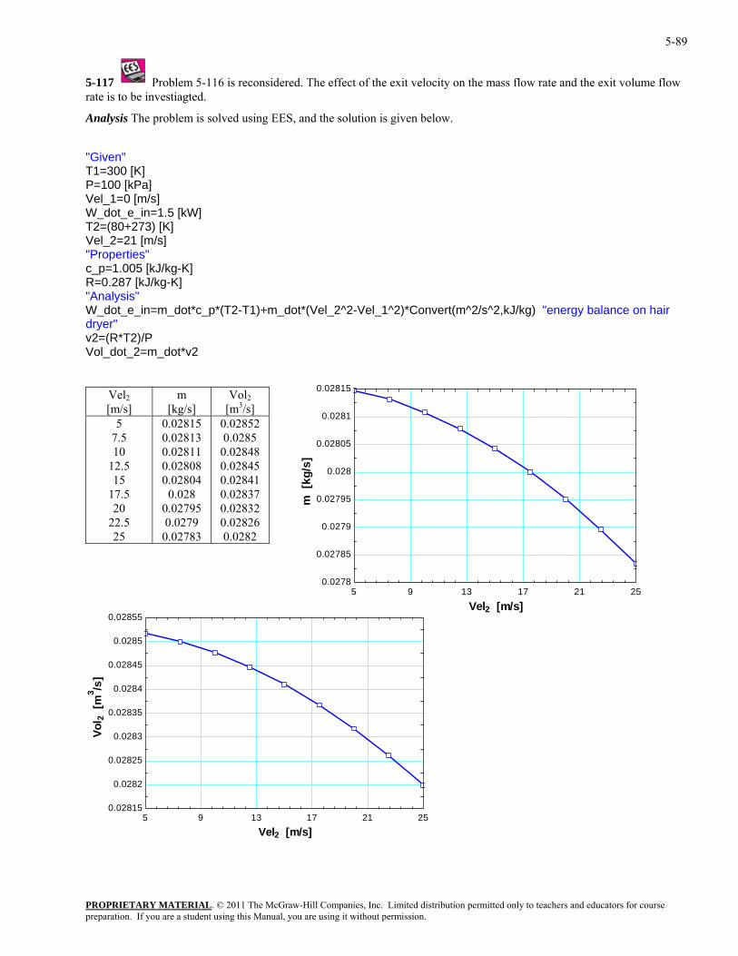
5-89
5-117 Problem 5-116 is reconsidered. The effect of the exit velocity on the mass flow rate and the exit volume flow rate is to be investiagted.
Analysis The problem is solved using EES, and the solution is given below.
"Given" T1=300 [K] P=100 [kPa] Vel_1=0 [m/s] W_dot_e_in=1.5 [kW] T2=(80+273) [K] Vel_2=21 [m/s] "Properties" c_p=1.005 [kJ/kg-K] R=0.287 [kJ/kg-K] "Analysis" W_dot_e_in=m_dot*c_p*(T2-T1)+m_dot*(Vel_2^2-Vel_1^2)*Convert(m^2/s^2,kJ/kg) "energy balance on hair dryer" v2=(R*T2)/P Vol_dot_2=m_dot*v2
Vel2 [m/s]
m [kg/s]
Vol2 [m3/s]
5 7.5 10
12.5 15
17.5 20
22.5 25
0.02815 0.02813 0.02811 0.02808 0.02804
0.028 0.02795 0.0279
0.02783
0.02852 0.0285
0.02848 0.02845 0.02841 0.02837 0.02832 0.02826 0.0282
5 9 13 17 21 250.02815
0.0282
0.02825
0.0283
0.02835
0.0284
0.02845
0.0285
0.02855
5 9 13 17 21 250.0278
0.02785
0.0279
0.02795
0.028
0.02805
0.0281
0.02815
Vel2 [m/s]
m [
kg/s
]
Vel2 [m/s]
Vol 2
[m
3 /s]
PROPRIETARY MATERIALpreparation. If you are a student using this Manual, you are using it without permission.
. © 2011 The McGraw-Hill Companies, Inc. Limited distribution permitted only to teachers and educators for course
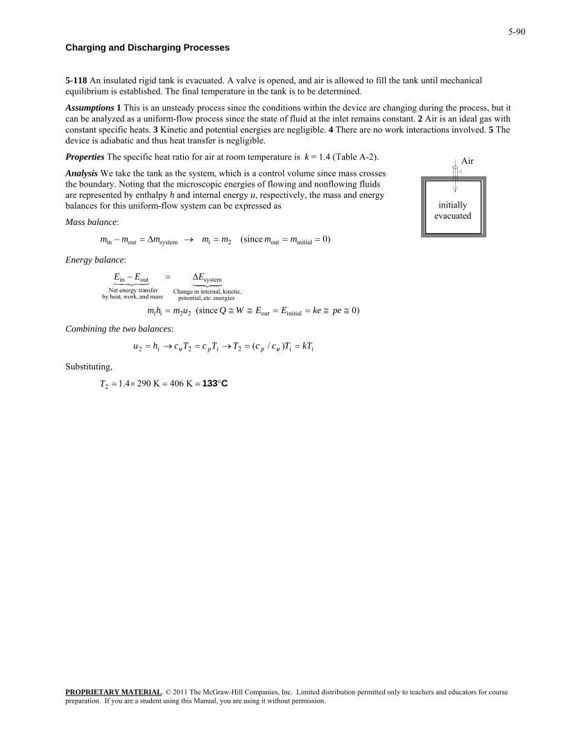
5-90
Charging and Discharging Processes
5-118 An insulated rigid tank is evacuated. A valve is opened, and air is allowed to fill the tank until mechanical equilibrium is established. The final temperature in the tank is to be determined.
Assumptions 1 This is an unsteady process since the conditions within the device are changing during the process, but it can be analyzed as a uniform-flow process since the state of fluid at the inlet remains constant. 2 Air is an ideal gas with constant specific heats. 3 Kinetic and potential energies are negligible. 4 There are no work interactions involved. 5 The device is adiabatic and thus heat transfer is negligible.
Properties The specific heat ratio for air at room temperature is k = 1.4 (Table A-2).
initially evacuated
Air Analysis We take the tank as the system, which is a control volume since mass crosses the boundary. Noting that the microscopic energies of flowing and nonflowing fluids are represented by enthalpy h and internal energy u, respectively, the mass and energy balances for this uniform-flow system can be expressed as
Mass balance:
)0 (since initialout2systemoutin ===→∆=− mmmmmmm i
Energy balance:
C
mass and work,heat,by nsferenergy traNet
)0 (since initialout22
energies etc. potential,kinetic, internal,in hange
systemoutin
≅≅==≅≅=
∆=−
peEEWQumhm
EEE
ii
4342143421
w balances:
ke
Combining the t o
iipipi kTTccTTcTchu ==→=→= )/(222 vv
Substituting,
C133°==×= K 406K 2901.42T
PROPRIETARY MATERIALpreparation. If you are a student using this Manual, you are using it without permission.
. © 2011 The McGraw-Hill Companies, Inc. Limited distribution permitted only to teachers and educators for course
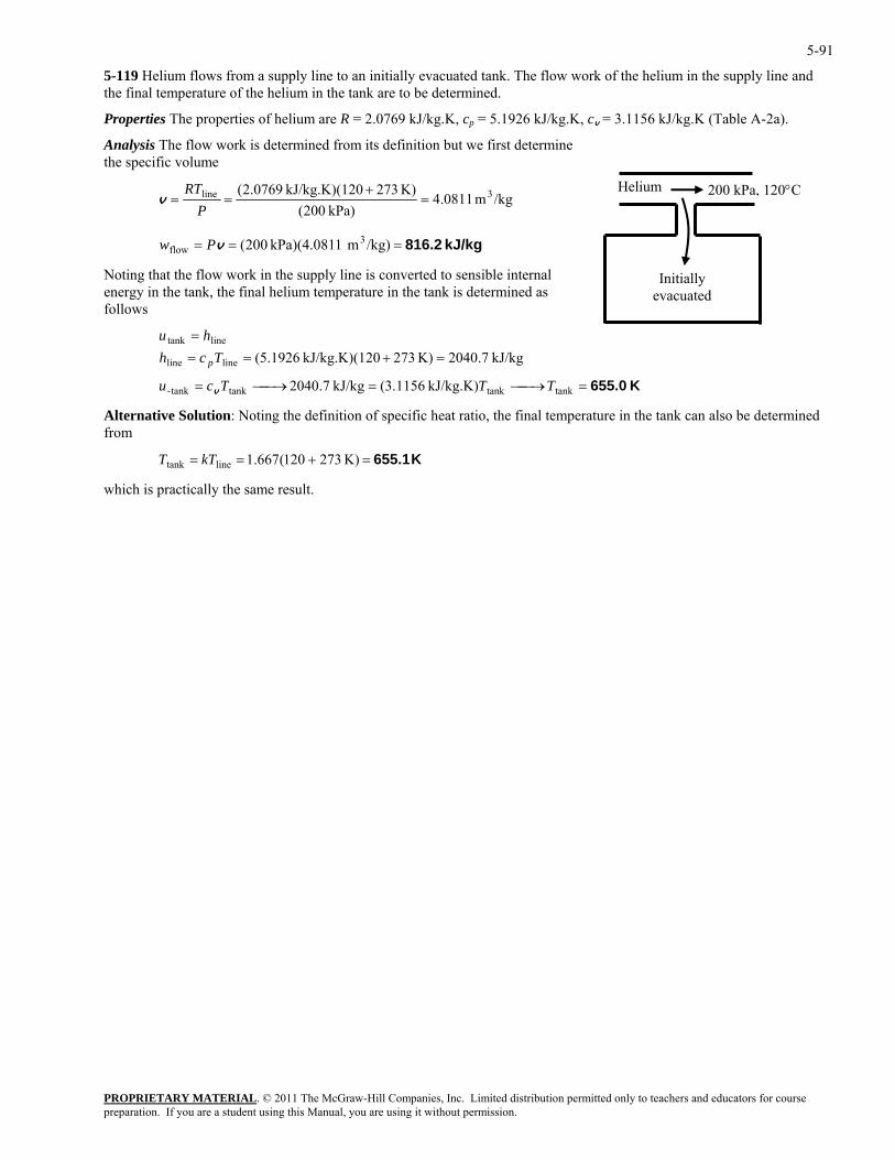
5-91
5-119 Helium flows from a supply line to an initially evacuated tank. The flow work of the helium in the supply line and the final temperature of the helium in the tank are to be determined.
Properties The properties of helium are R = 2.0769 kJ/kg.K, cp = 5.1926 kJ/kg.K, cv = 3.1156 kJ/kg.K (Table A-2a).
Analysis The flow work is determined from its definition but we first determine the specific volume
PROPRIETARY MATERIAL. © 2011 The McGraw-Hill Companies, Inc. Limited distribution permitted only to teachers and educators for course
/kgm 0811.4kPa) 200(
K) 27320kJ/kg.K)(1 0769.2( 3line =+
==P
RTv
kJ/kg 816.2=== /kg)m 1kPa)(4.081 200( 3flow vPw
Noting that the flow work in the supply line is converted to sensible internal energy in the tank, the final helium temperature in the tank is determined as follows
K 655.0=⎯→⎯=⎯→⎯=
=+===
tanktanktanktank-
lineline
linetank
kJ/kg.K) 1156.3(kJ/kg 7.2040
kJ/kg 7.2040K) 27320kJ/kg.K)(1 1926.5(
TTTcu
Tchhu
p
v
Helium
Initially evacuated
200 kPa, 120°C
Alternative Solution: Noting the definition of specific heat ratio, the final temperature in the tank can also be determined from
K 655.1=+== K) 273120(667.1linetank
which is practically the same result.
kTT
preparation. If you are a student using this Manual, you are using it without permission.
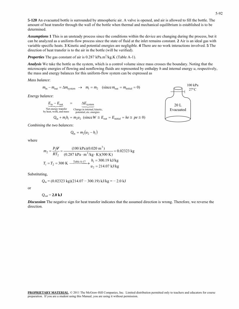
5-92
5-120 An evacuated bottle is surrounded by atmospheric air. A valve is opened, and air is allowed to fill the bottle. The amount of heat transfer through the wall of the bottle when thermal and mechanical equilibrium is established is to be determined.
Assumptions 1 This is an unsteady process since the conditions within the device are changing during the process, but it can be analyzed as a uniform-flow process since the state of fluid at the inlet remains constant. 2 Air is an ideal gas with variable specific heats. 3 Kinetic and potential energies are negligible. 4 There are no work interactions involved. 5 The direction of heat transfer is to the air in the bottle (will be verified).
Properties The gas constant of air is 0.287 kPa.m3/kg.K (Table A-1).
Analysis We take the bottle as the system, which is a control volume since mass crosses the boundary. Noting that the microscopic energies of flowing and nonflowing fluids are represented by enthalpy h and internal energy u, respectively, the mass and energy balances for this uniform-flow system can be expressed as
Mass balance: 100 kPa
27°C
20 L Evacuated
)0 (since initialout2systemoutin ===→∆=− mmmmmmm i
Energy balance:
C
mass and work,heat,by nsferenergy traNet
)0 (since initialout22in ≅=+ hmQ ii
energies etc. potential,kinetic, internal,in hange
systemoutin
≅≅==
∆=−
pekeEEWum
EEE4342143421
ing the two balances:
Combin
( )ihumQ −= 22in
where
PROPRIETARY MATERIAL. © 2011 The McGraw-Hill Companies, Inc. Limited distribution permitted only to teachers and educators for course
kJ/kg 214.07K 300
22 =
⎯⎯⎯⎯ →⎯==u
TTi
Substitutin
kJ/kg .19300
kg 0.02323)K 300)(K/kgmkPa 0.287(
17-A Table
32
22
=
=⋅⋅
==
hRT
m
i
g,
Qin = (0.02323 kg)(214.07 − 300.19) kJ/kg = − 2.0 kJ
or
Qout = 2.0 kJ
Discussion The negative sign for heat transfer indicates that the assumed direction is wrong. Therefore, we reverse the direction.
)m 0.020)(kPa 100( 3P V
preparation. If you are a student using this Manual, you are using it without permission.
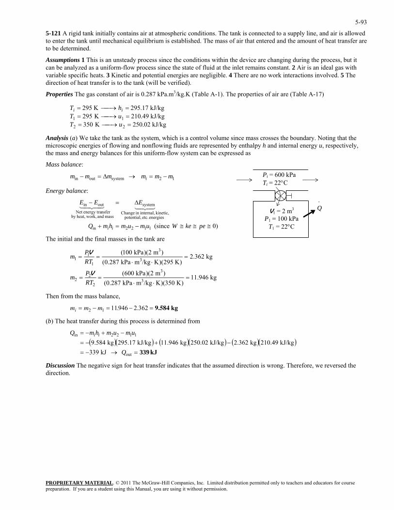
5-93
5-121 A rigid tank initially contains air at atmospheric conditions. The tank is connected to a supply line, and air is allowed to enter the tank until mechanical equilibrium is established. The mass of air that entered and the amount of heat transfer are to be determined.
Assumptions 1 This is an unsteady process since the conditions within the device are changing during the process, but it can be analyzed as a uniform-flow process since the state of fluid at the inlet remains constant. 2 Air is an ideal gas with variable specific heats. 3 Kinetic and potential energies are negligible. 4 There are no work interactions involved. 5 The direction of heat transfer is to the tank (will be verified).
Properties The gas constant of air is 0.287 kPa.m3/kg.K (Table A-1). The properties of air are (Table A-17)
kJ/kg 02.250K 350kJ/kg 49.210K 295kJ/kg 17.295K 295
22
11=⎯→⎯==⎯→⎯==⎯→⎯=
uTuThT ii
Analysis (a) We take the tank as the system, which is a control volume since mass crosses the boundary. Noting that the microscopic energies of flowing and nonflowing fluids are represented by enthalpy h and internal energy u, respectively, the mass and energy balances for this uniform-flow system can be expressed as
Mass balance:
PROPRIETARY MATERIAL. © 2011 The McGraw-Hill Companies, Inc. Limited distribution permitted only to teachers and educators for course
mmmmmm iPi = 600 kPa Ti = 22°C
V1 = 2 m3
P1 = 100 kPa T1 = 22°C
Q·
12systemoutin −=→∆=−
Energy balance:
)0 (since 1122in
energies etc. potential, kinetic, internal,in Change
system
mass and work,heat,by nsferenergy traNet
outin
≅≅≅−=+
∆=−
pekeWumumhmQ
EEE
ii
4342143421
The initial and the final masses in the tank are
kg
11.946)K 350)(K/kgmkPa 0.287( 3
22 =
⋅⋅==
RTm )m 2)(kPa 600(
kg 2.362)K 295)(K/kgm
)m 2)(kPa 100(
32
3
3=
⋅⋅
P
P
V
V
hen from e mass balance,
(b) The heat transfer during this process is determined from
Discussion The negative sign for heat transfer indicates that the assumed direction is wrong. Therefore, we reversed the direction.
kPa 0.287(1
11 ==
RTm
T th
m m mi = − = − =2 1 11 946 2 362. . 9.584 kg
( )( ) ( )( ) ( )( )kJ 339=→−=
−+−=−+−=
out
1122in
kJ 339kJ/kg 210.49kg 2.362kJ/kg 250.02kg 11.946kJ/kg 295.17kg 9.584
Q
umumhmQ ii
preparation. If you are a student using this Manual, you are using it without permission.
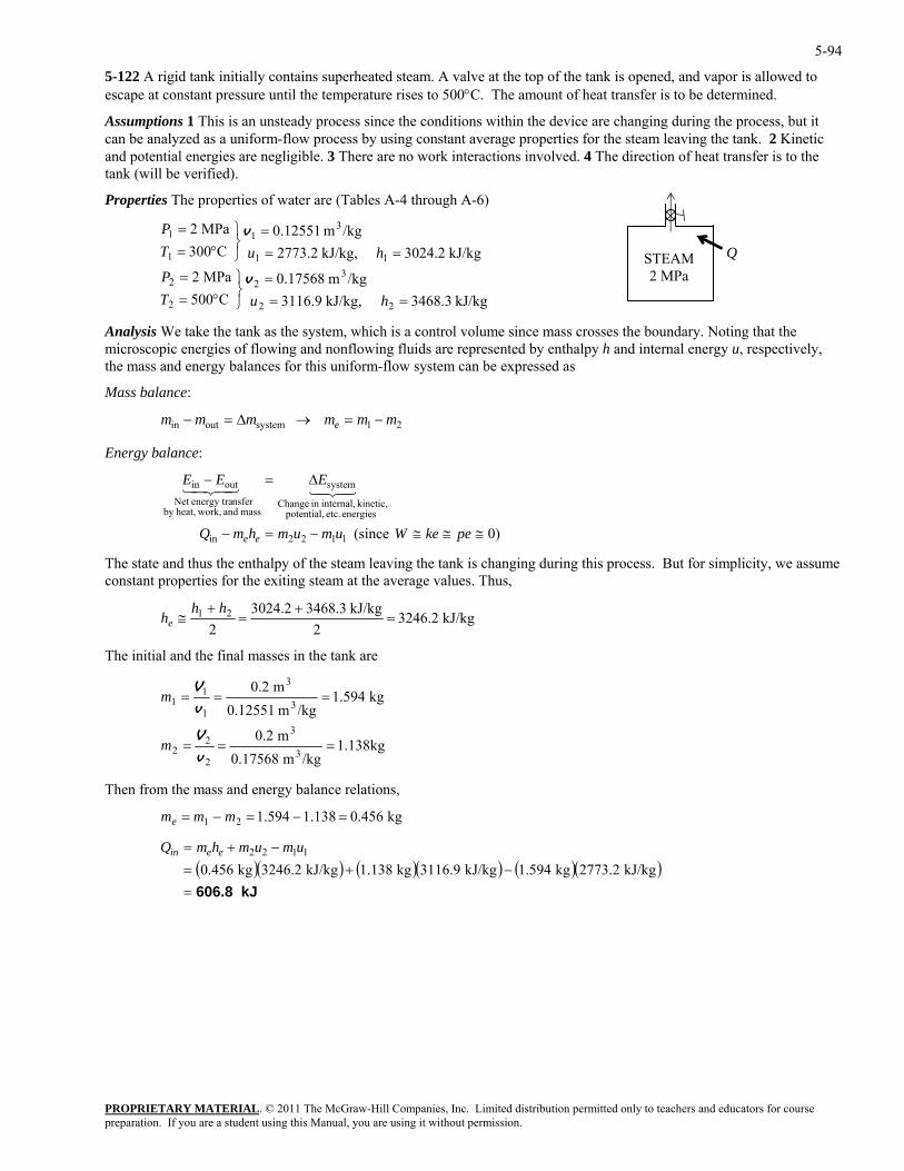
5-94
5-122 A rigid tank initially contains superheated steam. A valve at the top of the tank is opened, and vapor is allowed to escape at constant pressure until the temperature rises to 500°C. The amount of heat transfer is to be determined.
Assumptions 1 This is an unsteady process since the conditions within the device are changing during the process, but it can be analyzed as a uniform-flow process by using constant average properties for the steam leaving the tank. 2 Kinetic and potential energies are negligible. 3 There are no work interactions involved. 4 The direction of heat transfer is to the tank (will be verified).
Properties The properties of water are (Tables A-4 through A-6)
STEAM 2 MPa
Q
kJ/kg 3468.3,kJ/kg 3116.9/kgm 0.17568
C500MPa 2
kJ/kg 3024.2,kJ/kg 2773.2/kgm 0.12551
C300MPa 2
22
32
2
2
11
31
1
1
===
⎭⎬⎫
°==
===
⎭⎬⎫
°==
huTP
huTP
v
v
Analysis We take the tank as the system, which is a control volume since mass crosses the boundary. Noting that the microscopic energies of flowing and nonflowing fluids are represented by enthalpy h and internal energy u, respectively, the mass and energy balances for this uniform-flow system can be expressed as
Mass balance:
PROPRIETARY MATERIAL. © 2011 The McGraw-Hill Companies, Inc. Limited distribution permitted only to teachers and educators for course
mmmmmm e 21systemoutin −=→∆=−
Energy balance:
)0 (since 1122in
energies etc. potential, kinetic, internal,in Change
system
mass and work,heat,by nsferenergy traNet
outin
≅≅≅−=−
∆=−
pekeWumumhmQ
EEE
ee
4342143421
The state and thus the enthalpy of the steam leaving the tank is changing during this process. But for simplicity, we assume constant properties for the exiting steam at the average values. Thus,
kJ/kg 3246.222
21 =≅hekJ/kg 3468.33024.2
=++ hh
The initial and the final masses in the tank are
kg1.138/kgm 0.17568 3
22 v
m 0.2
kg 1.594/kgm 0.12551
m 0.2
32
3
3
1
11
===
===
V
v
V
m
m
hen from e mass and energy balance relations,
)
T th
kg 0.456138.1594.121 =−=−= mmme
( )( ) ( )( ) ( )(kJ 606.8=
−+=−+=
kJ/kg 2773.2kg 1.594kJ/kg 3116.9kg 1.138kJ/kg 3246.2kg 0.4561122 umumhmQ eein
preparation. If you are a student using this Manual, you are using it without permission.
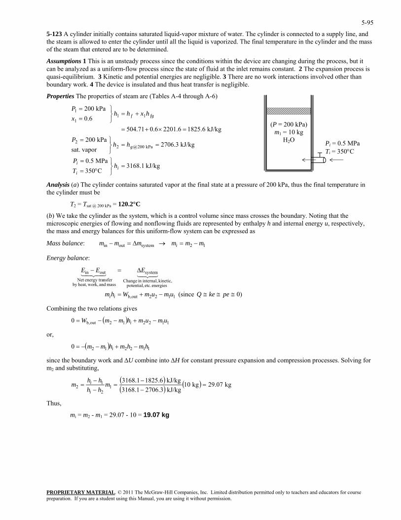
5-95
5-123 A cylinder initially contains saturated liquid-vapor mixture of water. The cylinder is connected to a supply line, and the steam is allowed to enter the cylinder until all the liquid is vaporized. The final temperature in the cylinder and the mass of the steam that entered are to be determined.
Assumptions 1 This is an unsteady process since the conditions within the device are changing during the process, but it can be analyzed as a uniform-flow process since the state of fluid at the inlet remains constant. 2 The expansion process is quasi-equilibrium. 3 Kinetic and potential energies are negligible. 3 There are no work interactions involved other than boundary work. 4 The device is insulated and thus heat transfer is negligible.
PROPRIETARY MATERIAL. © 2011 The McGraw-Hill Companies, Inc. Limited distribution permitted only to teachers and educators for course
kPa 002
⎭
=
=×+=
+=⎫=
hxhhP
Analysis (a) The cylinder contains saturated vapor at the final state at a pressure of 200 kPa, thus the final temperature in be
T Tsat @ 200 kPa = 120.2°C
, which is a control volume since mass crosses the boundary. Noting that the microscopic energies of flowing and nonflowing fluids are represented by enthalpy h and internal energy u, respectively, the mass and energy balances for this uniform-flow system can be expressed as
(P = 200 kPa) m1 = 10 kg
H2O Pi = 0.5 MPa Ti = 350°C
Properties The properties of steam are (Tables A-4 through A-6)
6.0 111 ⎭
⎬= fgfx1
kJ/kg .618252201.60.6504.71
kJ/kg 3168.1C350
MPa 0.5
kJ/kg 2706.3 vaporsat. kPa 200@2
=⎬⎫
°==
⎭⎬
ii
g
hTP
kPa 0022 =⎫=
hhP
i
the cylinder must
2 =
(b) We take the cylinder as the system
12systemoutin mmmmmm i −=→∆=− Mass balance:
Energy balance:
≅≅−+= pekeQumumWhm ii
43421
,
since the boundary work and ∆U combine into ∆H for constant pressure expansion and compression processes. Solving for m2 and substituting,
)0 (since 1122outb,
energies etc. potential, kinetic, internal,in Change
system
mass and work,heat,by nsferenergy traNet
outin ∆=− EEE43421
≅
Combining the two relations gives
( ) 112212outb,0 umumhmmW i −+−−=
or
( ) 1122120 hmhmhmm i −+−−=
( )( ) ( ) kg 9.072kg 10
kJ/kg 2706.33168.1kJ/kg .618253168.1
12
12 =
−−
=−−
= mhhhhm
i
i
Thus,
mi = m2 - m1 = 29.07 - 10 = 19.07 kg
preparation. If you are a student using this Manual, you are using it without permission.
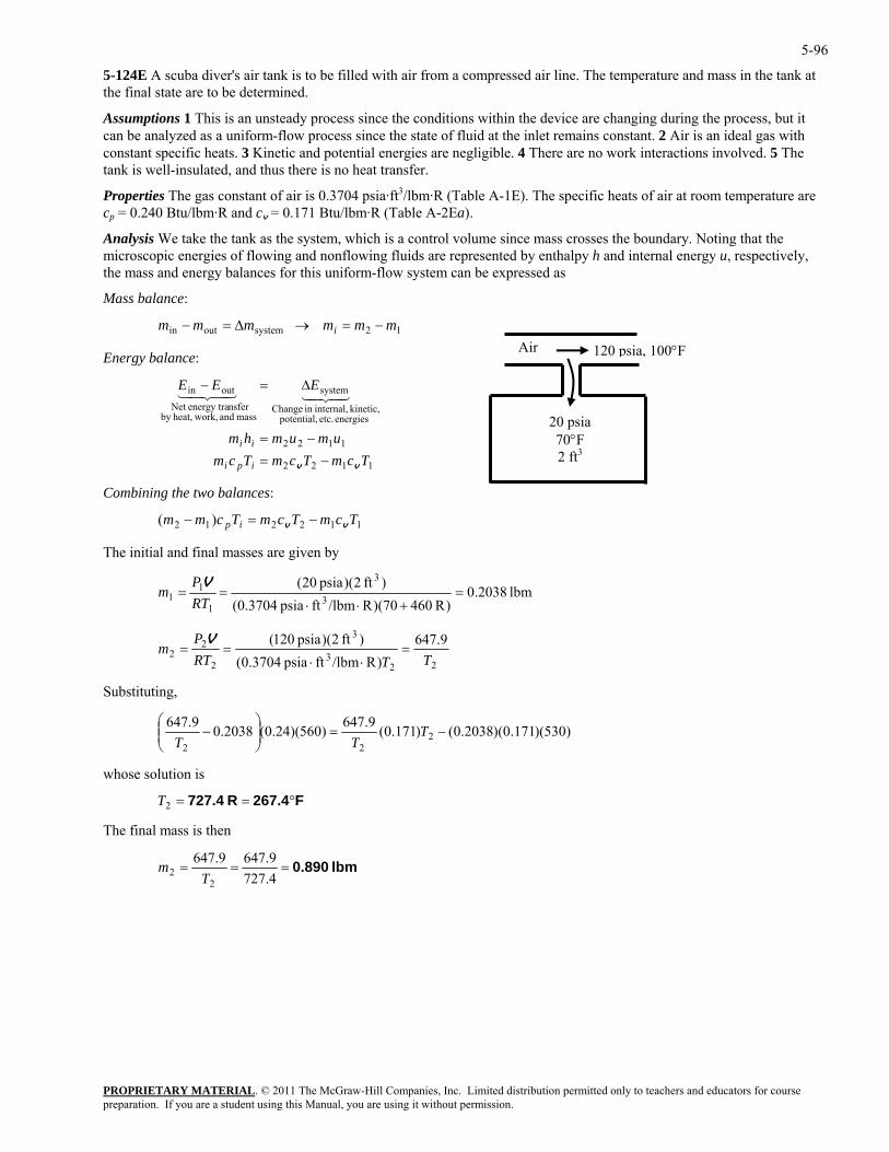
5-96
5-124E A scuba diver's air tank is to be filled with air from a compressed air line. The temperature and mass in the tank at the final state are to be determined.
Assumptions 1 This is an unsteady process since the conditions within the device are changing during the process, but it can be analyzed as a uniform-flow process since the state of fluid at the inlet remains constant. 2 Air is an ideal gas with constant specific heats. 3 Kinetic and potential energies are negligible. 4 There are no work interactions involved. 5 The tank is well-insulated, and thus there is no heat transfer.
Properties The gas constant of air is 0.3704 psia·ft3/lbm·R (Table A-1E). The specific heats of air at room temperature are cp = 0.240 Btu/lbm·R and cv = 0.171 Btu/lbm·R (Table A-2Ea).
Analysis We take the tank as the system, which is a control volume since mass crosses the boundary. Noting that the microscopic energies of flowing and nonflowing fluids are represented by enthalpy h and internal energy u, respectively, the mass and energy balances for this uniform-flow system can be expressed as
Mass balance:
PROPRIETARY MATERIAL. © 2011 The McGraw-Hill Companies, Inc. Limited distribution permitted only to teachers and educators for course
mmmmmm i 12systemoutin −=→∆=−
)( TcmTcmTcm v−=−
The initial and final masses are given by
20 psia70°F 2 ft3
120 psia, 100°F Air Energy balance:
1122
1122
energies etc. potential, kinetic, internal,in Change
system
mass and work,heat,by nsferenergy traNet
outin
TcmTcmTcmumumhm
EEE
ipi
ii
vv −=
−=
∆=−4342143421
Combining the two balances:
m 112212 ip v
lbm 2038.0)R 46070)(R/lbmftpsia 0.3704(
)ft 2)(psia 02(3
3
1
11 =
+⋅⋅==
RTP
mV
223
3
2
22m =
9.647)R/lbmftpsia 0.3704(
)ft 2)(psia 012(TTRT
P=
⋅⋅=
V
ubstituting,
S
)530)(171.0)(2038.0()171.0(9.647)560)(24.0(2038.09.647⎜⎜⎛
− 222
−=⎟⎟⎠
⎞
⎝T
TT
The final mass is then
whose solution is
F267.4R 727.4 °==2T
lbm 0.890===4.7279.6479.647
22 T
m
preparation. If you are a student using this Manual, you are using it without permission.
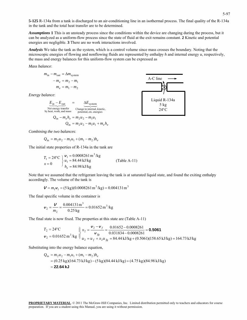
5-97
5-125 R-134a from a tank is discharged to an air-conditioning line in an isothermal process. The final quality of the R-134a in the tank and the total heat transfer are to be determined.
Assumptions 1 This is an unsteady process since the conditions within the device are changing during the process, but it can be analyzed as a uniform-flow process since the state of fluid at the exit remains constant. 2 Kinetic and potential energies are negligible. 3 There are no work interactions involved.
Analysis We take the tank as the system, which is a control volume since mass crosses the boundary. Noting that the microscopic energies of flowing and nonflowing fluids are represented by enthalpy h and internal energy u, respectively, the mass and energy balances for this uniform-flow system can be expressed as
Mass balance:
PROPRIETARY MATERIAL. © 2011 The McGraw-Hill Companies, Inc. Limited distribution permitted only to teachers and educators for course
mmmmm
mmm
e
e
−=−=
∆=−
Energy balance:
hmumumQumu
EEE
+−=−
∆=−
1122in
1122
energies etc. potential, kinetic, internal,in Change
system
mass and work,heat,by nsferenergy traNet
outin 4342143421
he initial state properties of R-134a in the t3=
e
v
quid state, and found the exiting enthalpy
The final specific volume in the container is
A-C line
Liquid R-134a 5 kg 24°C
21
12
systemoutin
m−
ee mhmQ =−in
ee
Combining the two balances:
ehmmumumQ )( 211122in −+−=
T ank are
kJ/kg 98.84kJ/kg 44.84
0C24
1
11
==
⎭⎬⎫
=°=
hu
xT
(Table A-11) /kgm 0008261.0
Note that we assumed that the refrigerant leaving the tank is at saturated liaccordingly. The volume of the tank is
3311 m 004131.0)/kgm 0008261.0)(kg 5( === vV m
/kgm 0.01652kg 25.0
m 004131.0 33
2
2 ===mV
v
The final state is now fixed. The properties at this state are (Table A-11)
kJ/kg 73.164)kJ/kg 65.158)(5061.0(kJ/kg 44.84
0008261.0031834.00008261.001652.0
/kgm 01652.0
C24
22
22
32
2
=+=+=
=−−
=−
=
⎪⎭
⎪⎬⎫
=
°=
fgf
fg
f
uxuu
xT 0.5061v
vv
v
Substituting into the energy balance equation,
kJ 22.64=
+−=−+−=
)kJ/kg 98.84)(kg 75.4()kJ/kg 44.84)(kg 5()kJ/kg 73.164)(kg 25.0()( 211122in ehmmumumQ
preparation. If you are a student using this Manual, you are using it without permission.
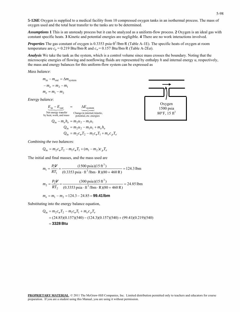
5-98
5-126E Oxygen is supplied to a medical facility from 10 compressed oxygen tanks in an isothermal process. The mass of oxygen used and the total heat transfer to the tanks are to be determined.
Assumptions 1 This is an unsteady process but it can be analyzed as a uniform-flow process. 2 Oxygen is an ideal gas with constant specific heats. 3 Kinetic and potential energies are negligible. 4 There are no work interactions involved.
Properties The gas constant of oxygen is 0.3353 psia·ft3/lbm·R (Table A-1E). The specific heats of oxygen at room temperature are cp = 0.219 Btu/lbm·R and cv = 0.157 Btu/lbm·R (Table A-2Ea).
Analysis We take the tank as the system, which is a control volume since mass crosses the boundary. Noting that the microscopic energies of flowing and nonflowing fluids are represented by enthalpy h and internal energy u, respectively, the mass and energy balances for this uniform-flow system can be expressed as
Mass balance:
PROPRIETARY MATERIAL. © 2011 The McGraw-Hill Companies, Inc. Limited distribution permitted only to teachers and educators for course
mmmmm
mmm
e −=−
∆=−
Energy balance:
umumhmQ
EEE
+−=+−
−=−
∆=−
1122in
1122
1122in
energies etc. potential, kinetic, internal,in Change
system
mass and work,heat,by nsferenergy traNet
outin
vv
4342143421
The initial and final masses, and the mass used are
Oxygen 1500 psia
80°F, 15 ft3
21
12
systemoutin
me =−
epe
ee
ee
TcmTcmTcmQhmumumQ =in
Combining the two balances:
epTcmmTcmTcmQ )( 211122in −+−= vv
lbm 3.124)R 46080)(R/lbmftpsia 0.3353(
)ft 15)(psia 0150(3
3
1
11 =
+⋅⋅==
RTP
mV
lbm 85.24)R 46080)(R/lbmftpsia 0.3353(
)ft 15)(psia 030(2P V 3
3
2=
+⋅⋅==
RTm
Substituting into the energy balance equation,
2
lbm 99.41=−=−= 85.243.12421 mmme
Btu 3328=+−=
+−=
)540)(219.0)(41.99()540)(157.0)(3.124()540)(157.0)(85.24(1122in epe TcmTcmTcmQ vv
preparation. If you are a student using this Manual, you are using it without permission.
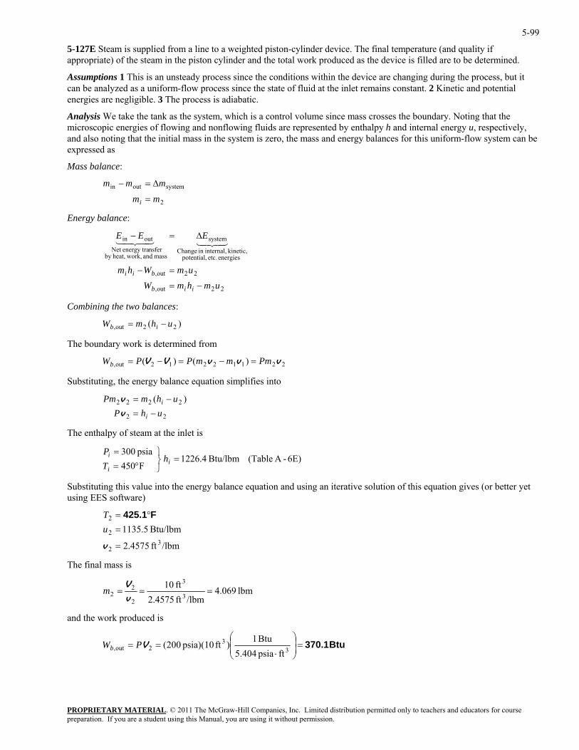
5-99
5-127E Steam is supplied from a line to a weighted piston-cylinder device. The final temperature (and quality if appropriate) of the steam in the piston cylinder and the total work produced as the device is filled are to be determined.
Assumptions 1 This is an unsteady process since the conditions within the device are changing during the process, but it can be analyzed as a uniform-flow process since the state of fluid at the inlet remains constant. 2 Kinetic and potential energies are negligible. 3 The process is adiabatic.
Analysis We take the tank as the system, which is a control volume since mass crosses the boundary. Noting that the microscopic energies of flowing and nonflowing fluids are represented by enthalpy h and internal energy u, respectively, and also noting that the initial mass in the system is zero, the mass and energy balances for this uniform-flow system can be expressed as
Mass balance:
2
systemoutin
mm
mmm
i =
∆=−
Energy balance:
PROPRIETARY MATERIAL. © 2011 The McGraw-Hill Companies, Inc. Limited distribution permitted only to teachers and educators for course
out,
energies etc. potential,kinetic, internal,in ange
systemoutin
umWhm
EEE
bii =−
∆=−4342143421
ombining the two balances:
he boundary work is determined from
Ch
mass and work,heat,by nsferenergy traNet
2 2
22out, umhmW iib −=
C
)( 22out, uhmW ib −=
T
22112212out, )()( vvvVV PmmmPPWb =−=−=
Substituting, the energy balance equation simplifies into
−=
The enthalpy of steam at the inlet is
alue into the energy balance equation and using an iterative solution of this equation gives (or better yet sing EES oftware)
=
=
v
u
The final mass is
2
2222 )(uhP
uhmPm
i
i
−=v
v
2
6E)-A (Table Btu/lbm 4.1226F450psia 300
=⎭⎬⎫
°==
ii
i hTP
Substituting this vu s
2 °=T F425.1
/lbmft 4575.2
Btu/lbm 5.11353
2
2
lbm 069.4/lbmft 4575.2
ft 103
3
2
22 ===
v
Vm
and the work produced is
Btu 370.1=⎟⎟⎠
⎞⎜⎜⎝
⎛
⋅==
33
2out,ftpsia 5.404
Btu 1)ft psia)(10 200(VPWb
preparation. If you are a student using this Manual, you are using it without permission.
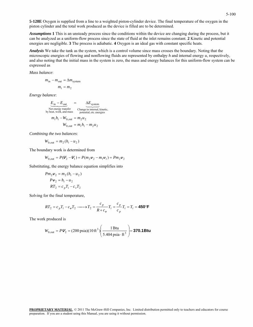
5-100
5-128E Oxygen is supplied from a line to a weighted piston-cylinder device. The final temperature of the oxygen in the piston cylinder and the total work produced as the device is filled are to be determined.
Assumptions 1 This is an unsteady process since the conditions within the device are changing during the process, but it can be analyzed as a uniform-flow process since the state of fluid at the inlet remains constant. 2 Kinetic and potential energies are negligible. 3 The process is adiabatic. 4 Oxygen is an ideal gas with constant specific heats.
Analysis We take the tank as the system, which is a control volume since mass crosses the boundary. Noting that the microscopic energies of flowing and nonflowing fluids are represented by enthalpy h and internal energy u, respectively, and also noting that the initial mass in the system is zero, the mass and energy balances for this uniform-flow system can be expressed as
Mass balance:
PROPRIETARY MATERIAL. © 2011 The McGraw-Hill Companies, Inc. Limited distribution permitted only to teachers and educators for course
m
mmm
=
∆=−
Energy balance:
22out,
energies etc. potential, kinetic, internal,in Change
system
mass and work,heat,by nsferenergy traNet
outin
umhumWhm
EEE
ii
bii
−
=−
∆=−4342143421
ombining the two balances:
he boundary work is determined from
2
systemoutin
mi
out, mWb = 22
C
)( 22out, uhmW ib −=
T
22112212out, )()( vvvVV PmmmPPWb =−=−=
S gubstitutin , the energy balance equation simplifies into
TcTcRTuhP
vip
i
−=−=v
perature,
22
22
2222 )( uhmPm i −=v
Solving for the final tem
F450°===+
=⎯→⎯−= iip
pi
pip TT
cc
TcR
cTTcTcRT
vv 222
The work produced is
Btu 370.1=⎟⎟⎠
⎞⎜⎜⎝
⎛
⋅==
33
2out,ftpsia 5.404
Btu 1)ft psia)(10 200(VPWb
preparation. If you are a student using this Manual, you are using it without permission.
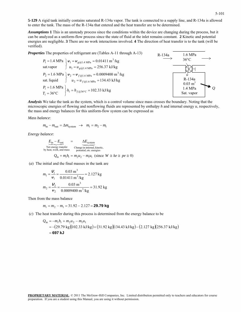
5-101
5-129 A rigid tank initially contains saturated R-134a vapor. The tank is connected to a supply line, and R-134a is allowed to enter the tank. The mass of the R-134a that entered and the heat transfer are to be determined.
Assumptions 1 This is an unsteady process since the conditions within the device are changing during the process, but it can be analyzed as a uniform-flow process since the state of fluid at the inlet remains constant. 2 Kinetic and potential energies are negligible. 3 There are no work interactions involved. 4 The direction of heat transfer is to the tank (will be verified).
Properties The properties of refrigerant are (Tables A-11 through A-13)
R-134a 0.03 m3
1.4 MPa Sat. vapor
1.6 MPa 36°C
R-134a
kJ/kg .33102C36MPa 1.6
kJ/kg 134.43/kgm 0.0009400
liquid sat.MPa 1.6
kJ/kg 256.37/kgm 0.01411
vaporsat.MPa 1.4
C36@
MPa 1.6@2
3MPa 1.6@22
MPa 1.4@1
3MPa 1.4@11
==⎭⎬⎫
°==
====
⎭⎬⎫=
====
⎭⎬⎫=
°fii
i
f
f
g
g
hhTP
uuP
uuP
vv
vv
Q
Analysis We take the tank as the system, which is a control volume since mass crosses the boundary. Noting that the microscopic energies of flowing and nonflowing fluids are represented by enthalpy h and internal energy u, respectively, the mass and energy balances for this uniform-flow system can be expressed as
Mass balance:
PROPRIETARY MATERIAL. © 2011 The McGraw-Hill Companies, Inc. Limited distribution permitted only to teachers and educators for course
mmmmmm i 12systemoutin −=→∆=−
Energy balance:
)0 (since 1122in
energies etc. potential, kinetic, internal,in Change
system
mass and work,heat,by nsferenergy traNet
outin
≅≅≅−=+
∆=−
pekeWumumhmQ
EEE
ii
4342143421
(a) The initial and the final masses in the tank are
kg 92.31/kgm 0.0009400 3
22 ===
vm
m 0.03
kg 127.2/kg
m 0.03
32
3
3=
V
V
Then from e mass balance
(c) The heat transfer during this process is determined from the energy balance to be
)
m 0.014111
11 ==
vm
th
kg 29.79=−=−= 127.292.3112 mmmi
( )( ) ( )( ) ( )( kJ 697=
−+−=−+−=
kJ/kg 256.37kg 2.127kJ/kg 134.43kg 31.92kJ/kg 102.33kg 29.79 1122in umumhmQ ii
preparation. If you are a student using this Manual, you are using it without permission.
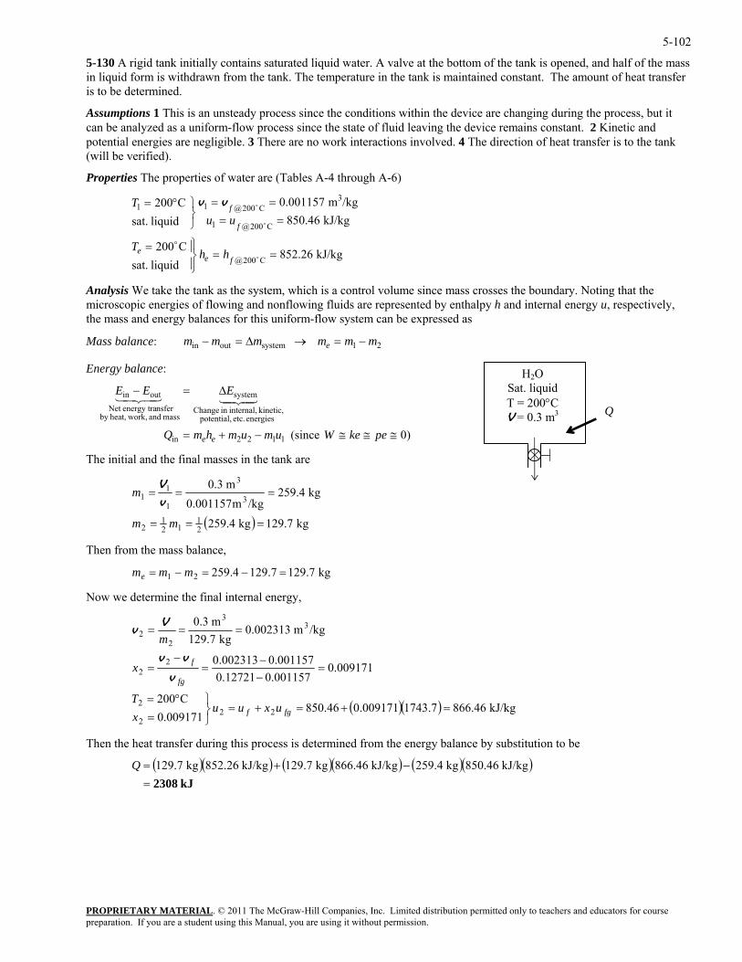
5-102
5-130 A rigid tank initially contains saturated liquid water. A valve at the bottom of the tank is opened, and half of the mass in liquid form is withdrawn from the tank. The temperature in the tank is maintained constant. The amount of heat transfer is to be determined.
Assumptions 1 This is an unsteady process since the conditions within the device are changing during the process, but it can be analyzed as a uniform-flow process since the state of fluid leaving the device remains constant. 2 Kinetic and potential energies are negligible. 3 There are no work interactions involved. 4 The direction of heat transfer is to the tank (will be verified).
Properties The properties of water are (Tables A-4 through A-6)
kJ/kg 852.26liquid sat.
C200
kJ/kg 850.46/kgm 0.001157
liquid sat.C200
C200@
C200@1
3C200@11
==⎪⎭
⎪⎬⎫=
====
⎭⎬⎫°=
o
o
o
o
fee
f
f
hhT
uuT vv
Analysis We take the tank as the system, which is a control volume since mass crosses the boundary. Noting that the microscopic energies of flowing and nonflowing fluids are represented by enthalpy h and internal energy u, respectively, the mass and energy balances for this uniform-flow system can be expressed as
PROPRIETARY MATERIAL. © 2011 The McGraw-Hill Companies, Inc. Limited distribution permitted only to teachers and educators for course
mmmmmm eMass balance: in 21systemout −=→∆=−
Energy balance: H2O Sat. liquid T = 200°C V = 0.3 m3 Q
)0 (since 1122in
energies etc. potential, kinetic, internal,in Change
system
mass and work,heat,by nsferenergy traNet
outin
≅≅≅−+=
∆=−
pekeWumumhmQ
EEE
ee
4342143421
The initial and the final masses in the tank are
( ) kg 129.7kg 259.4
kg 259.4/kgm0.0011571
11 ==m
v m 0.3
21
121
2
3
3
===
=
mm
V
=−=−= mmm
Now we determine the final internal energy,
Then from the mass balance,
kg 129.77.1294.25921e
( )( ) kJ/kg 866.467.1743009171.046.850009171.0
C200
009171.0001157.012721.0001157.0002313.0
/kgm 0.002313kg 129.7
m 0.3
222
2
22
33
22
=+=+=⎭⎬⎫
=°=
=−−
=−
=
===
fgf
fg
f
uxuuxT
x
m
v
vv
Vv
Then the heat transfer during this process is determined from the energy balance by substitution to be
( )( ) ( )( ) ( )( )
kJ 2308=−+= kJ/kg 850.46kg 259.4kJ/kg 866.46kg 129.7kJ/kg 852.26kg 129.7Q
preparation. If you are a student using this Manual, you are using it without permission.
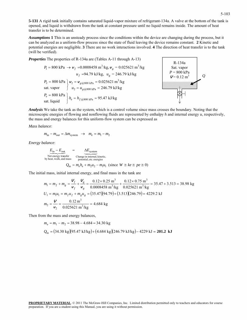
5-103
5-131 A rigid tank initially contains saturated liquid-vapor mixture of refrigerant-134a. A valve at the bottom of the tank is opened, and liquid is withdrawn from the tank at constant pressure until no liquid remains inside. The amount of heat transfer is to be determined.
Assumptions 1 This is an unsteady process since the conditions within the device are changing during the process, but it can be analyzed as a uniform-flow process since the state of fluid leaving the device remains constant. 2 Kinetic and potential energies are negligible. 3 There are no work interactions involved. 4 The direction of heat transfer is to the tank (will be verified).
Properties The properties of R-134a are (Tables A-11 through A-13)
PROPRIETARY MATERIAL. © 2011 The McGraw-Hill Companies, Inc. Limited distribution permitted only to teachers and educators for course
/kgm 0.025621= /kg,m 0.0008458 kPa 800
kPa 800@
kPa 800@2
33
==⎭⎬⎫=
==⎭
=→=
fee
g
gf
hhP
uu
P vv
he tank as the system, which is a control volume since mass crosses the boundary. Noting that the icroscopi energies of flowing and nonflowing fluids are represented by enthalpy h and internal energy u, respectively,
essed as
Mass balance:
R-134a Sat. vapor
P = 800 kPa V = 0.12 m3 Q
1
/kgm 0.025621kPa 800
kJ/kg 79.246= kJ/kg, 79.94 3
kPa 800@22 ==⎬⎫=
=
g
gf
P
uu
vv
kJ/kg 95.47liquid sat.
kPa 800
kJ/kg 246.79 vaporsat.
Analysis We take tm cthe mass and energy balances for this uniform-flow system can be expr
21systemoutin mmmmmm e −=→∆=−
Energy balance:
energies etc. potential, kinetic, internal,in Change
system
mass and work,heat,by nsferenergy traNet
outin
≅≅≅
∆=−
pekeWum
EEE4342143421
he initial mass, initial internal energy, and final mass in the tank are
22in −+= umhmQ ee )0 (since 11
T
( )( ) ( )( )
kg 684.4/kgm 0.025621
m 20.1
kJ 2.4229246.793.51394.7935.47
kg .9838.5133.4735/kgm 0.025621m 0.750.12
/kgm 0.0008458m 0.250.12
3
3
22
111
3
3
3
3
1
===
=+=+==
=+=×
+×
=+=+=
vV
v
V
v
V
m
umumumU
mmm
ggff
g
g
f
fgf
Then from the mass and energy balances,
kg .3034684.498.3821 =−=−= mmme
( )( ) ( )( ) kJ 201.2=−+= kJ 4229kJ/kg 246.79kg 4.684kJ/kg 95.47kg 34.30inQ
preparation. If you are a student using this Manual, you are using it without permission.
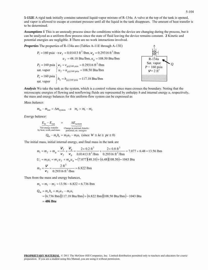
5-104
5-132E A rigid tank initially contains saturated liquid-vapor mixture of R-134a. A valve at the top of the tank is opened, and vapor is allowed to escape at constant pressure until all the liquid in the tank disappears. The amount of heat transfer is to be determined.
Assumptions 1 This is an unsteady process since the conditions within the device are changing during the process, but it can be analyzed as a uniform-flow process since the state of fluid leaving the device remains constant. 2 Kinetic and potential energies are negligible. 3 There are no work interactions involved.
Properties The properties of R-134a are (Tables A-11E through A-13E)
PROPRIETARY MATERIAL. © 2011 The McGraw-Hill Companies, Inc. Limited distribution permitted only to teachers and educators for course
/lbmft 0.29316 /lbm,ft 0.01413 psia 160
psia 160@
psia 160@2
33
==⎭⎬⎫=
==⎭
==→=
gee
g
gf
hhP
uu
P vv
he tank as the system, which is a control volume since mass crosses the boundary. Noting that the icroscopi energies of flowing and nonflowing fluids are represented by enthalpy h and internal energy u, respectively,
essed as
Mass balance:
R-134a Sat. vapor
P = 160 psia V = 2 ft3
Q
1
/lbmft 0.29316psia 160
Btu/lbm 50.108 Btu/lbm, 10.48 3
psia 160@22 ==⎬⎫=
==
g
gf
vP
uu
v
Btu/lbm 117.18 vaporsat.
psia 160
Btu/lbm 108.50 vaporsat.
Analysis We take tm cthe mass and energy balances for this uniform-flow system can be expr
21systemoutin mmmmmm e −=→∆=−
Energy balance:
energies etc. potential, kinetic, internal,in Change
system
mass and work,heat,by nsferenergy traNet
outin
≅≅≅
∆=−
pekeW
EEE4342143421
he initial mass, initial internal energy, and final mass in the tank are
)0 (since 1122in −=− umumhmQ ee
T
( )( ) ( )( )
lbm .8226/lbmft 0.29316
ft 2
Btu 1043108.506.4848.107.077
lbm .56136.48077.7/lbmft 0.29316
ft 0.82/lbmft 0.01413
ft 0.22
3
3
22
111
3
3
3
3
1
===
=+=+==
=+=×
+×
=+=+=
vV
v
V
v
V
m
umumumU
mmm
ggff
g
g
f
fgf
Then from the mass and energy balances,
lbm 736.6822.656.1321 =−=−= mmme
( )( ) ( )( )Btu 486=
−+=−+=
Btu 1043Btu/lbm 108.50lbm 6.822Btu/lbm 117.18lbm 6.7361122in umumhmQ ee
preparation. If you are a student using this Manual, you are using it without permission.
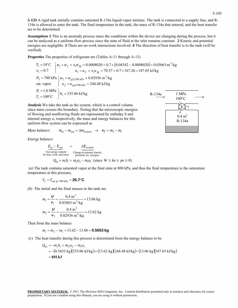
5-105
5-133 A rigid tank initially contains saturated R-134a liquid-vapor mixture. The tank is connected to a supply line, and R-134a is allowed to enter the tank. The final temperature in the tank, the mass of R-134a that entered, and the heat transfer are to be determined.
Assumptions 1 This is an unsteady process since the conditions within the device are changing during the process, but it can be analyzed as a uniform-flow process since the state of fluid at the inlet remains constant. 2 Kinetic and potential energies are negligible. 3 There are no work interactions involved. 4 The direction of heat transfer is to the tank (will be verified).
Properties The properties of refrigerant are (Tables A-11 through A-13)
( )
kJ/kg 335.06
PROPRIETARY MATERIAL. © 2011 The McGraw-Hill Companies, Inc. Limited distribution permitted only to teachers and educators for course
100 ⎭⎬°=i CT
MPa 1.0
kJ/kg 244.48/kgm 0.02936
vaporsat.kPa 007
26.1670.7.57077.0
kPa 700@2
3kPa 700@22
111
⎫=
====
⎭⎬⎫=
×+=+=⎭⎬=
i
g
g
fgf
P
uuP
uxuux
vv
kJ/kg 187.65/kgm 0.030630.00080200.043420.70.0008020C14 3
11
=
==−×+=+=⎫°=
i
fgf
h
xT vvv
the tank as the system, which is a control volume nce mass crosses the boundary. Noting that the microscopic energies f flowing and nonflowing fluids are represented by enthalpy h and
xpressed as
ass balance:
1
1 MPa 100°C
0.4 m3
R-134a
R-134a
Analysis We takesiointernal energy u, respectively, the mass and energy balances for this uniform-flow system can be e
12systemoutin mmmmmm i −=→∆=− M
Energy balance:
Change
mass and work,heat,by nsferenergy traNet
)0 (since 1122in
energies etc. potential,kinetic, internal,in
systemoutin
≅≅−=+
∆=−
pekeWumumhmQ
EEE
ii
4342143421
perature is the saturation mperature at this pressure,
(b) The initial and the final masses in the tank are
≅
(a) The tank contains saturated vapor at the final state at 800 kPa, and thus the final temte
C26.7°== kPa 700 @sat 2 TT
kg .6213/kgm 0.02936
m 0.4
kg .0613/kgm 0.03063
m 0.4
3
3
22
3
3
11
===
===
vV
vV
m
m
Then from the mass balance
(c) The heat transfer during this process is determined from the energy balance to be
)
kg 0.5653=−=−= 06.1362.1312 mmmi
( )( ) ( )( ) ( )(kJ 691=
−+−=−+−=
kJ/kg 187.65kg 13.06kJ/kg 244.48kg 13.62kJ/kg 335.06kg 0.5653 1122in umumhmQ ii
preparation. If you are a student using this Manual, you are using it without permission.
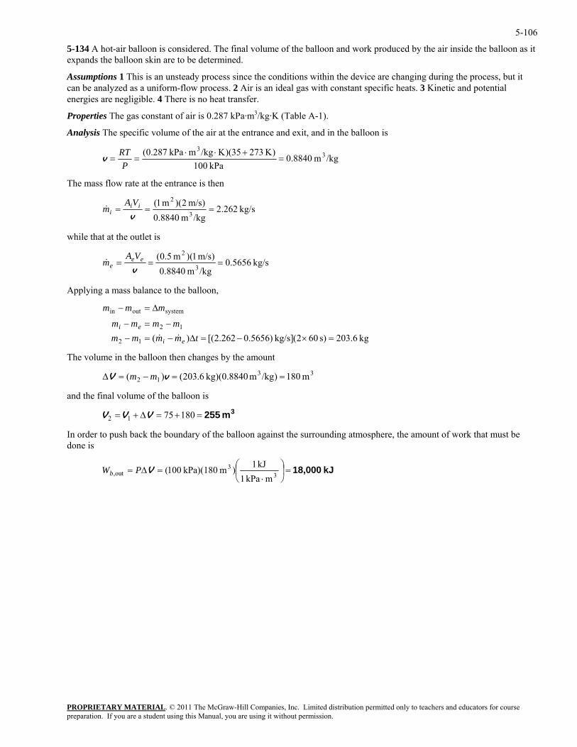
5-106
5-134 A hot-air balloon is considered. The final volume of the balloon and work produced by the air inside the balloon as it expands the balloon skin are to be determined.
Assumptions 1 This is an unsteady process since the conditions within the device are changing during the process, but it can be analyzed as a uniform-flow process. 2 Air is an ideal gas with constant specific heats. 3 Kinetic and potential energies are negligible. 4 There is no heat transfer.
Properties The gas constant of air is 0.287 kPa·m3/kg·K (Table A-1).
Analysis The specific volume of the air at the entrance and exit, and in the balloon is
/kgm 8840.0kPa 100
)K 27335)(K/kgmkPa 0.287( 33
=+⋅⋅
==P
RTv
The mass flow rate at the entrance is then
PROPRIETARY MATERIAL. © 2011 The McGraw-Hill Companies, Inc. Limited distribution permitted only to teachers and educators for course
kg/s 262.2/kgm 8.0
==vim&
840)m/s 2()m 1(
3
2=iiVA
hile that at the outlet is w
kg/s 5656.0/kgm 8840.0 3
===vem&
)m/s 1()m 5.0( 2eeVA
pplying a mass balance to the balloon,
12
=×−−=− mmmm ei
he volum in the balloon then changes by the amount
and the final volume of the balloon is
In order to push back the boundary of the balloon against the surrounding atmosphere, the amount of work that must be done is
A
systemoutin ∆=− mmm
[()(12 =∆−=− tmmmm ei && kg 6.203s) 602(kg/s] )5656.0262.2
T e
3312 m 180)/kgm kg)(0.8840 6.203()( ==−=∆ vV mm
3m 255=+=∆+= 1807512 VVV
kJ 18,000=⎟⎠
⎞⎜⎝
⎛
⋅=∆=
33
out,mkPa 1
kJ 1)m kPa)(180 100(VPWb
preparation. If you are a student using this Manual, you are using it without permission.
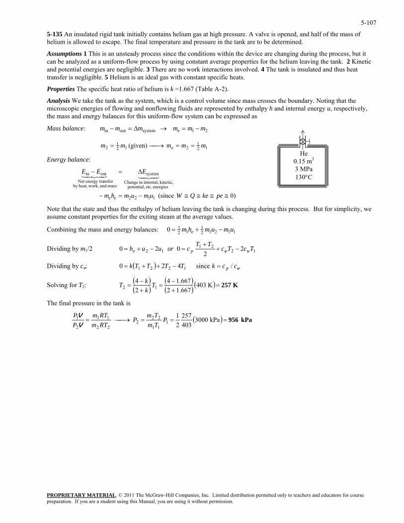
5-107
5-135 An insulated rigid tank initially contains helium gas at high pressure. A valve is opened, and half of the mass of helium is allowed to escape. The final temperature and pressure in the tank are to be determined.
Assumptions 1 This is an unsteady process since the conditions within the device are changing during the process, but it can be analyzed as a uniform-flow process by using constant average properties for the helium leaving the tank. 2 Kinetic and potential energies are negligible. 3 There are no work interactions involved. 4 The tank is insulated and thus heat transfer is negligible. 5 Helium is an ideal gas with constant specific heats.
Properties The specific heat ratio of helium is k =1.667 (Table A-2).
Analysis We take the tank as the system, which is a control volume since mass crosses the boundary. Noting that the microscopic energies of flowing and nonflowing fluids are represented by enthalpy h and internal energy u, respectively, the mass and energy balances for this uniform-flow system can be expressed as
PROPRIETARY MATERIAL. © 2011 The McGraw-Hill Companies, Inc. Limited distribution permitted only to teachers and educators for course
mmmmmm eMass balance: in 21systemout −=→∆=−
121
2121
2 (given) mmmmm e ==⎯→⎯=
Energy balance:
energies etc. potential, kinetic, internal,in Change
system
mass and work,heat,by nsferenergy traNet
outin 4342143421
)0 (s 1122 −=− umumhm ee ince ≅≅≅≅
∆=−
pekeQW
EEE
d thus the enthalpy of helium leaving the tank is changing during this process. But for simplicity, we operties for the exiting steam at the average values.
and energy balances:
He 0.15 m3
3 MPa 130°C
Note that the state anassume constant pr
0 12 1
12 1 2 1 1= + −m h m u m ue Combining the mass
1221
12 22
02Dividing by m1/2 0 he= TcTcTT
coruu p vv −++
=−+
ividing by cv: ( ) vcckTTTTk p / since420 1221 =−++= D
( )( )
( )( ) ( ) K 257=+−
=+−
= K 4031.66721.6674
24
12 TkkT Solving for T2:
The final pressure in the tank is
( ) kPa 956===⎯→⎯= kPa 3000403257
21
111
222
22
11
2
1 PTmTm
PRTmRTm
PP
V
V
preparation. If you are a student using this Manual, you are using it without permission.
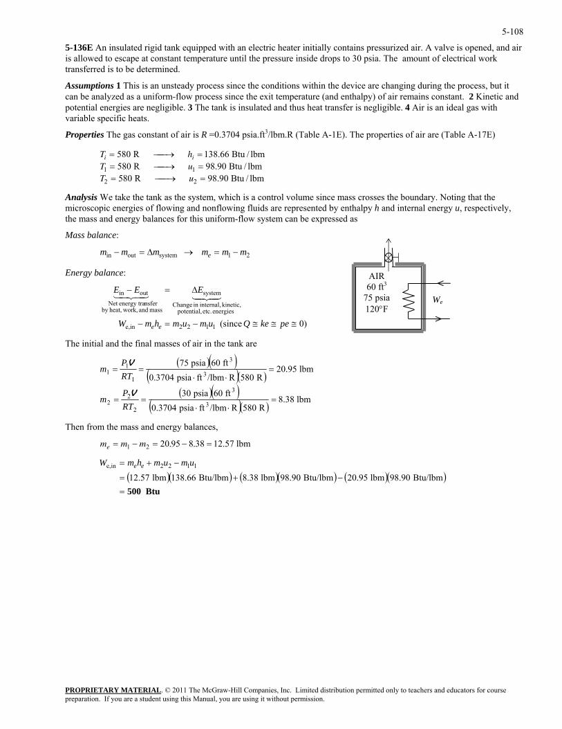
5-108
5-136E An insulated rigid tank equipped with an electric heater initially contains pressurized air. A valve is opened, and air is allowed to escape at constant temperature until the pressure inside drops to 30 psia. The amount of electrical work transferred is to be determined.
Assumptions 1 This is an unsteady process since the conditions within the device are changing during the process, but it can be analyzed as a uniform-flow process since the exit temperature (and enthalpy) of air remains constant. 2 Kinetic and potential energies are negligible. 3 The tank is insulated and thus heat transfer is negligible. 4 Air is an ideal gas with variable specific heats.
Properties The gas constant of air is R =0.3704 psia.ft3/lbm.R (Table A-1E). The properties of air are (Table A-17E)
PROPRIETARY MATERIAL. © 2011 The McGraw-Hill Companies, Inc. Limited distribution permitted only to teachers and educators for course
= ⎯ →⎯ =580 R 138.66 Btu / lbm
e tank as the system, which is a control volume since mass crosses the boundary. Noting that the of flowing and nonflowing fluids are represented by enthalpy h and internal energy u, respectively,
the mass and energy balances for this uniform-flow system can be expressed as
mmmmmm e
i iT hT uT u= ⎯ →⎯ == ⎯ →⎯ =
580 R 98.90 Btu / lbm580 R 98.90 Btu / lbm
1 1
2 2
Analysis We take thmicroscopic energies
Mass balance:
AIR 60 ft3
75 psia 120°F
We
21systemoutin −=→∆=−
The initial and the final masses of air in the tank are
Energy balance:
)0 (since 1122ine,
energies etc. potential, kinetic, internal,in Change
system
mass and work,heat,by nsferenergy traNet
outin
≅≅≅−=−
∆=−
pekeQumumhmW
EEE
ee
4342143421
( )( )( )( )
( )( )( )( )
lbm 8.38R 580R/lbmftpsia 0.3704
ft 60psia 30
lbm 20.95R 580R/lbmftpsia 0.3704
ft
3
3
2
22
3
3
1
=⋅⋅
==
=⋅⋅
==
RTP
m
RTm
V
Then from the mass and energy balances,
60psia 751PV1
m m me = − = − =1 2 20 95 8 38. . 12.57 lbm
( )( ) ( )( ) ( )( )Btu 500=
−+=
−+=
Btu/lbm 98.90lbm 20.95Btu/lbm 98.90lbm 8.38Btu/lbm 138.66lbm 12.571122ine, umumhmW ee
preparation. If you are a student using this Manual, you are using it without permission.
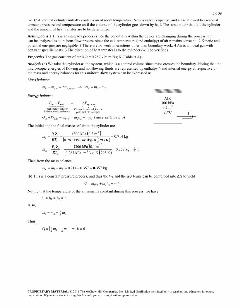
5-109
5-137 A vertical cylinder initially contains air at room temperature. Now a valve is opened, and air is allowed to escape at constant pressure and temperature until the volume of the cylinder goes down by half. The amount air that left the cylinder and the amount of heat transfer are to be determined.
Assumptions 1 This is an unsteady process since the conditions within the device are changing during the process, but it can be analyzed as a uniform-flow process since the exit temperature (and enthalpy) of air remains constant. 2 Kinetic and potential energies are negligible. 3 There are no work interactions other than boundary work. 4 Air is an ideal gas with constant specific heats. 5 The direction of heat transfer is to the cylinder (will be verified).
Properties The gas constant of air is R = 0.287 kPa.m3/kg.K (Table A-1).
Analysis (a) We take the cylinder as the system, which is a control volume since mass crosses the boundary. Noting that the microscopic energies of flowing and nonflowing fluids are represented by enthalpy h and internal energy u, respectively, the mass and energy balances for this uniform-flow system can be expressed as
Mass balance:
PROPRIETARY MATERIAL. © 2011 The McGraw-Hill Companies, Inc. Limited distribution permitted only to teachers and educators for course
mmmmmm e
AIR 300 kPa 0.2 m3
20°C
21systemoutin −=→∆=−
Energy balance:
)0 (since 1122inb,in
energies etc. potential, kinetic, internal,in Change
system
mass and work,heat,by nsferenergy traNet
outin
≅≅−=−+
∆=−
pekeumumhmWQ
EEE
ee
4342143421
The initial and the final masses of air in the cylinder are
( )( )( )( )
( )( )
( )( ) 1232
2 kg 0.357K 293K/kgmkPa 0.287
mRT
m =⋅⋅
== 13
22
3
3
1
m 0.1kPa 300
kg 0.714K 293K/kgm
m 0.2kPa 300
P
P
=
=⋅⋅
V
V
(b) This i hus the Wb and the ∆U terms can be combined into ∆H to yield
111
kPa 0.287RTm ==
Then from the mass balance,
m m me = − = − =1 2 0 714 0 357. . 0.357 kg
s a constant pressure process, and t
Q m h m h m he e= + −2 2 1 1
Noting that the temperature of the air remains constant during this process, we have
hi = h1 = h2 = h.
lso, A
121
2 mmme == .
Thus,
( ) 0=−+= hmmmQ 1121
121
preparation. If you are a student using this Manual, you are using it without permission.
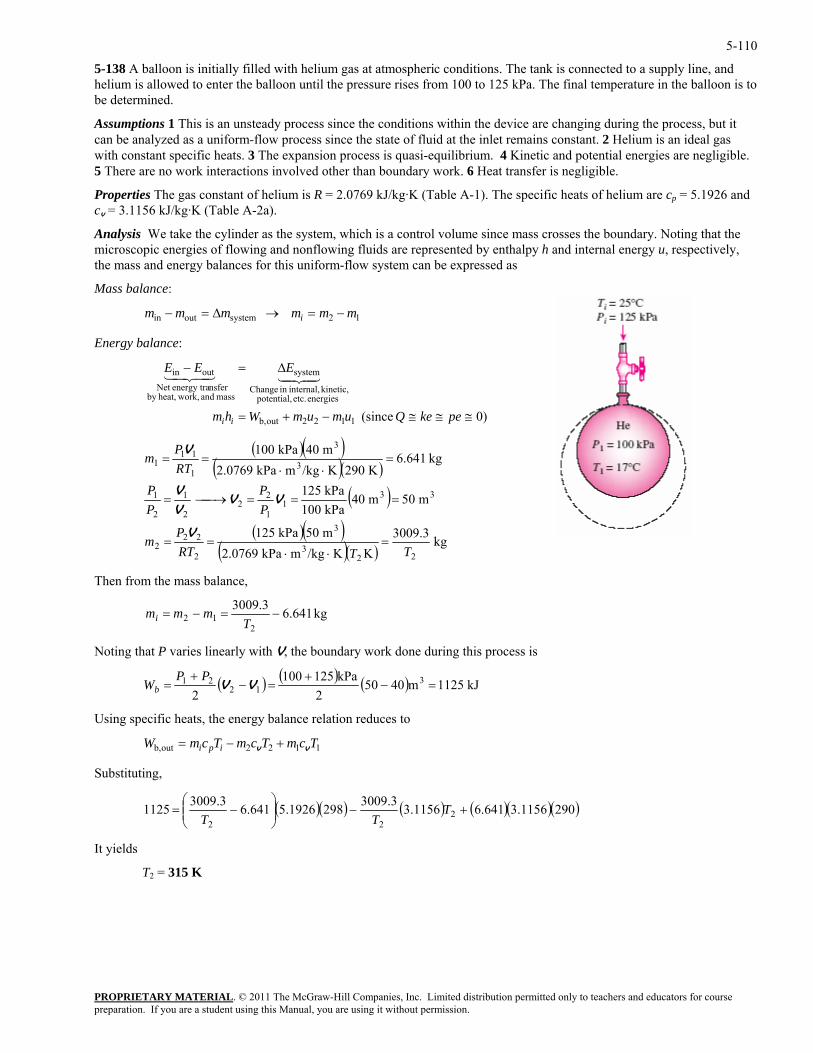
5-110
5-138 A balloon is initially filled with helium gas at atmospheric conditions. The tank is connected to a supply line, and helium is allowed to enter the balloon until the pressure rises from 100 to 125 kPa. The final temperature in the balloon is to be determined.
Assumptions 1 This is an unsteady process since the conditions within the device are changing during the process, but it can be analyzed as a uniform-flow process since the state of fluid at the inlet remains constant. 2 Helium is an ideal gas with constant specific heats. 3 The expansion process is quasi-equilibrium. 4 Kinetic and potential energies are negligible. 5 There are no work interactions involved other than boundary work. 6 Heat transfer is negligible.
Properties The gas constant of helium is R = 2.0769 kJ/kg·K (Table A-1). The specific heats of helium are cp = 5.1926 and cv = 3.1156 kJ/kg·K (Table A-2a).
Analysis We take the cylinder as the system, which is a control volume since mass crosses the boundary. Noting that the microscopic energies of flowing and nonflowing fluids are represented by enthalpy h and internal energy u, respectively, the mass and energy balances for this uniform-flow system can be expressed as
Mass balance:
12systemoutin mmmmmm i −=→∆=−
Energy balance:
)0 (since 1122outb,
energies etc. potential, kinetic, internal,in Change
system
mass and work,heat,by nsferenergy traNet
outin
≅≅≅−+=
∆=−
pekeQumumWhm
EEE
ii
4342143421
( )( )( )( )
( )( )( )
( )( )kg 3009.3
KK/kgmkPa 2.0769m 50kPa 125
m 50m 40kPa 100kPa 125
kg 641.6K 290K/kgmkPa 2.0769
m 40kPa 100
223
3
2
222
331
1
22
11
3
3
1
111
TTRTm
PP
PP
RTP
m
=⋅⋅
==
===⎯→⎯=
=⋅⋅
==
VVV
V
V
22
P V
Then from the mass balance,
kg 641.63.3009
212 −=−=
Tmmmi
Noting that P varies linearly with V, the boundary work done during this process is
( ) ( ) ( ) kJ 1125m40502
kPa1251002
312
21 =−+
=−+
=Wb VVPP
sing specific heats, the energy balance relation reduces to
g,
U
1122outb, TcmTcmTcmW ipi vv +−=
Substitutin
( )( ) ( ) ( )( )(2901156.3641.61156.33.30092981926.5641.63.30091125 222
+−⎟⎟⎠
⎞⎜⎜⎝
⎛−= T
TT )
It yields
T2 = 315 K
PROPRIETARY MATERIALpreparation. If you are a student using this Manual, you are using it without permission.
. © 2011 The McGraw-Hill Companies, Inc. Limited distribution permitted only to teachers and educators for course
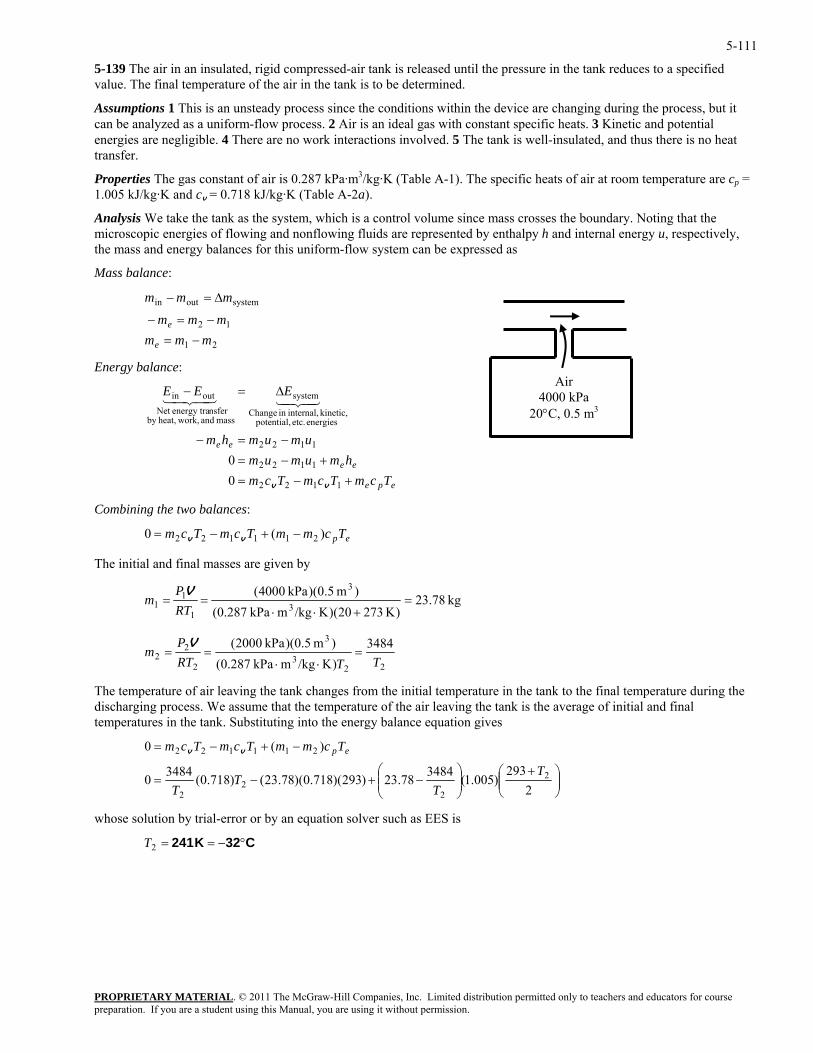
5-111
5-139 The air in an insulated, rigid compressed-air tank is released until the pressure in the tank reduces to a specified value. The final temperature of the air in the tank is to be determined.
Assumptions 1 This is an unsteady process since the conditions within the device are changing during the process, but it can be analyzed as a uniform-flow process. 2 Air is an ideal gas with constant specific heats. 3 Kinetic and potential energies are negligible. 4 There are no work interactions involved. 5 The tank is well-insulated, and thus there is no heat transfer.
Properties The gas constant of air is 0.287 kPa·m3/kg·K (Table A-1). The specific heats of air at room temperature are cp = 1.005 kJ/kg·K and cv = 0.718 kJ/kg·K (Table A-2a).
Analysis We take the tank as the system, which is a control volume since mass crosses the boundary. Noting that the microscopic energies of flowing and nonflowing fluids are represented by enthalpy h and internal energy u, respectively, the mass and energy balances for this uniform-flow system can be expressed as
Mass balance:
PROPRIETARY MATERIAL. © 2011 The McGraw-Hill Companies, Inc. Limited distribution permitted only to teachers and educators for course
mmmmm
mmm
e −=−
∆=−
Energy balance:
umumhm
EEE
+−=+−
−=−
∆=−
1122
1122
1122
energies etc. potential, kinetic, internal,in Change
system
mass and work,heat,by nsferenergy traNet
outin
0 vv
4342143421
The initial and final masses are given by
Air 4000 kPa
20°C, 0.5 m3
21
12
systemoutin
me =−
epe
ee
ee
TcmTcmTcmhmumum=0
Combining the two balances:
epTcmmTcmTcm )(0 211122 −+−= vv
kg 78.23)K 27320)(K/kgmkPa 0.287( 3
11 =
+⋅⋅==
RTm
)m 5.0)(kPa 0400( 31PV
22
3
32 3484)m 5.0)(kPa 0200(P
m ===V
22
)K/kgmkPa 0.287( TTRT ⋅⋅
he temperature of air leaving the tank changes from the initial temperature in the tank the final temperature during the discharging process. We assume that the temperature of the air leaving the tank is the average of initial and final temperatures in the tank. Substituting into the energy balance equation gives
T to
−+−= )(0 TcmmTcmTcm
⎟⎟⎠
⎞⎜⎜⎝
⎛ +⎟⎟⎠
⎞⎜⎜⎝
⎛−+−=
2293
)005.1(348478.23)293)(718.0)(78.23()718.0(34840 2
22
2
211122
TT
TT
epvv
whose solution by trial-error or by an equation solver such as EES is
C32K 241 °−==2T
preparation. If you are a student using this Manual, you are using it without permission.
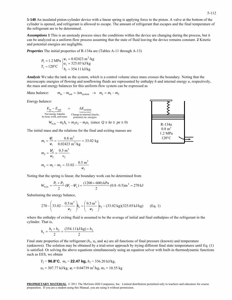
5-112
5-140 An insulated piston-cylinder device with a linear spring is applying force to the piston. A valve at the bottom of the cylinder is opened, and refrigerant is allowed to escape. The amount of refrigerant that escapes and the final temperature of the refrigerant are to be determined.
Assumptions 1 This is an unsteady process since the conditions within the device are changing during the process, but it can be analyzed as a uniform-flow process assuming that the state of fluid leaving the device remains constant. 2 Kinetic and potential energies are negligible.
Properties The initial properties of R-134a are (Tables A-11 through A-13)
kJ/kg 11.354kJ/kg 03.325
/kgm 02423.0
C120MPa 2.1
1
1
31
1
1
===
⎭⎬⎫
°==
hu
TP v
Analysis We take the tank as the system, which is a control volume since mass crosses the boundary. Noting that the microscopic energies of flowing and nonflowing fluids are represented by enthalpy h and internal energy u, respectively, the mass and energy balances for this uniform-flow system can be expressed as
PROPRIETARY MATERIAL. © 2011 The McGraw-Hill Companies, Inc. Limited distribution permitted only to teachers and educators for course
mmmmmm eMass balance: in 21systemout −=→∆=−
Energy balance:
R -134a0.8 m3
1.2 MPa 120°C
)0 (since 1122inb,
energies etc. potential, kinetic, internal,in Change
system
mass and work,heat,by nsferenergy traNet
outin
≅≅≅−=−
∆=−
pekeQumumhmW
EEE
ee
4342143421
The initial mass and the relations for the final and exiting masses are
2
3
21 02.33 −=−= mme
2
3
2
22
3
m 0.5
m 0.5
m 0.8
v
vV
V
==
m
vm
31
11 kg 02.33
/kgm 0.02423v===m
Noting that the spring is linear, the boundary work can be determined from
kJ 270m0.5)-0.8(2
kPa 600)(1200)(2
321
21inb, =
+=−
+= VV
PPW
Substituting the energy balance,
kJ/kg) kg)(325.03 02.33(m 5.0m 5.002.33270 22
3
2
3−⎟
⎟⎠
⎞⎜⎜⎝
⎛=⎟
⎟⎠
⎞⎜⎜⎝
⎛−− uhe vv
(Eq. 1)
where th age of initial and final enthalpies of the refrigerant in the cylinder. That is,
e enthalpy of exiting fluid is assumed to be the aver
2kJ/kg) 11.354(
2221 hhh
he+
=+
=
Final state properties of the refrigerant (h2, u2, and v2) are all functions of final pressure (known) and temperature (unknown). The solution may be obtained by a trial-error approach by trying different final state temperatures until Eq. (1) is satisfied. Or solving the above equations simultaneously using an equation solver with built-in thermodynamic functions such as EES, we obtain
T2 = 96.8°C, me = 22.47 kg, h2 = 336.20 kJ/kg,
u2 = 307.77 kJ/kg, v2 = 0.04739 m3/kg, m2 = 10.55 kg
preparation. If you are a student using this Manual, you are using it without permission.
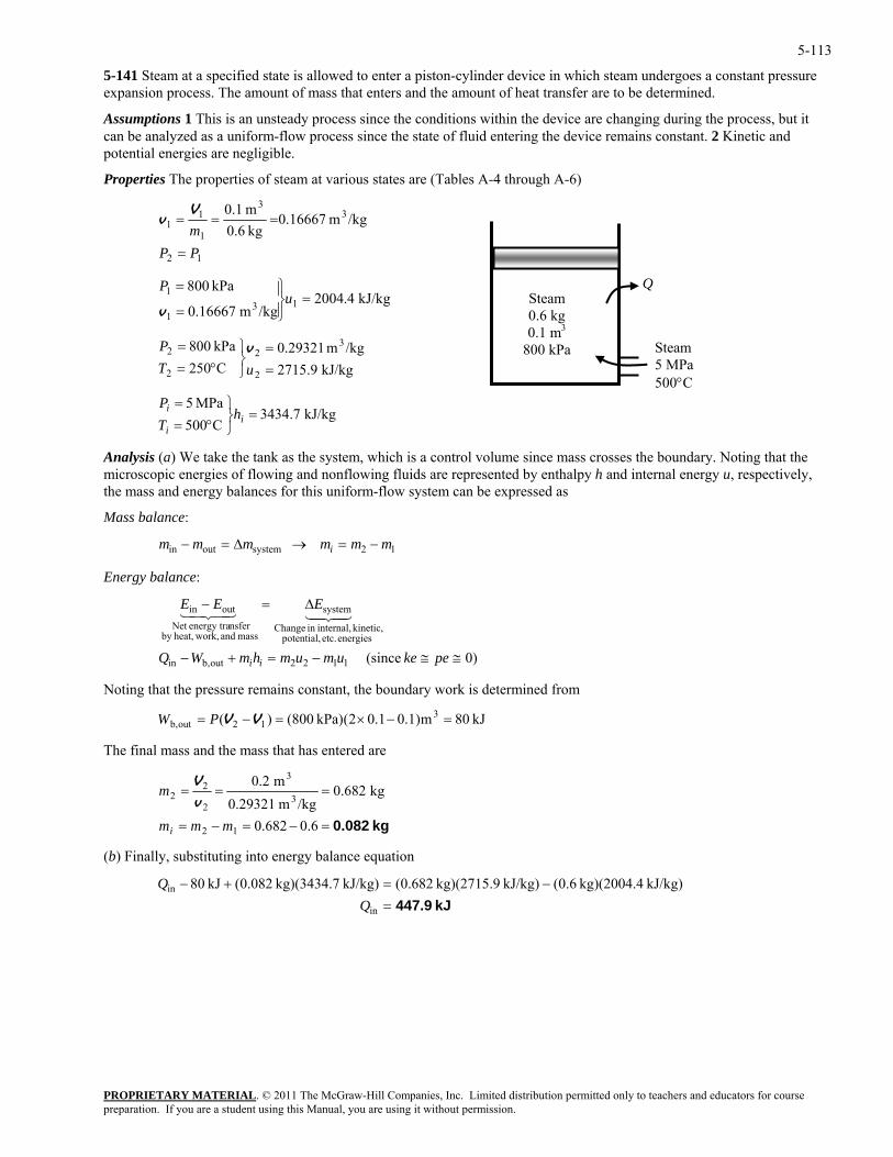
5-113
5-141 Steam at a specified state is allowed to enter a piston-cylinder device in which steam undergoes a constant pressure expansion process. The amount of mass that enters and the amount of heat transfer are to be determined.
Assumptions 1 This is an unsteady process since the conditions within the device are changing during the process, but it can be analyzed as a uniform-flow process since the state of fluid entering the device remains constant. 2 Kinetic and potential energies are negligible.
Properties The properties of steam at various states are (Tables A-4 through A-6)
PROPRIETARY MATERIAL. © 2011 The McGraw-Hill Companies, Inc. Limited distribution permitted only to teachers and educators for course
12
33
1
11 /kgm 16667.0
kg 0.6m 0.1
PPm
=
===V
v
1 kJ/kg 4.2004/kgm 16667.0
kPa 80013
1=
⎪⎭
⎪⎬⎫
=
=u
P
v
kPa 800 22 =
⎬⎫=P v
Analysis ( ake the tank as the system, which is a control volume since mass crosses the boundary. Noting that the es of flowing and nonflowing fluids are represented by enthalpy h and internal energy u, respectively,
gy balances for this uniform-flow system can be expressed as
Mass balance:
Q
Steam 5 MPa 500°C
Steam 0.6 kg 0.1 m3
800 kPa /kgm 29321.0 3
kJ/kg 9.2715C250 22 =⎭°= uT
kJ/kg 7.3434MPa 5
=⎬⎫=
ii h
P
C500°=iT ⎭
a) We tmicroscopic energithe mass and ener
12systemoutin mmmmmm i −=→∆=−
Energy balance:
e
kinetic, internal,in Changeby
≅≅ peke
43421
ing that the pressure remains constant, the boundary s determined from
12outb, =−×=−= VVPW
mass and work,heat,nsferenergy traNet
43421 systemoutin ∆=− EEE
(sinc 1122outb,in
energies etc. potential,
−=+− umumhmWQ ii )0
Not work i3 kJ 80m0.1)0.12(kPa) (800)(
The final mass and the mass that has entered are
kg 0.082=−=−=
===
6.0682.0
kg 682.0/kgm 0.29321
m 0.2
12
3
3
2
22
mmm
m
i
v
V
(b) Finally, substituting into energy balance equation
kJ 447.9=−=+−
in
in
kJ/kg) kg)(2004.4 6.0(kJ/kg) kg)(2715.9 682.0(kJ/kg) kg)(3434.7 082.0(kJ 80
preparation. If you are a student using this Manual, you are using it without permission.
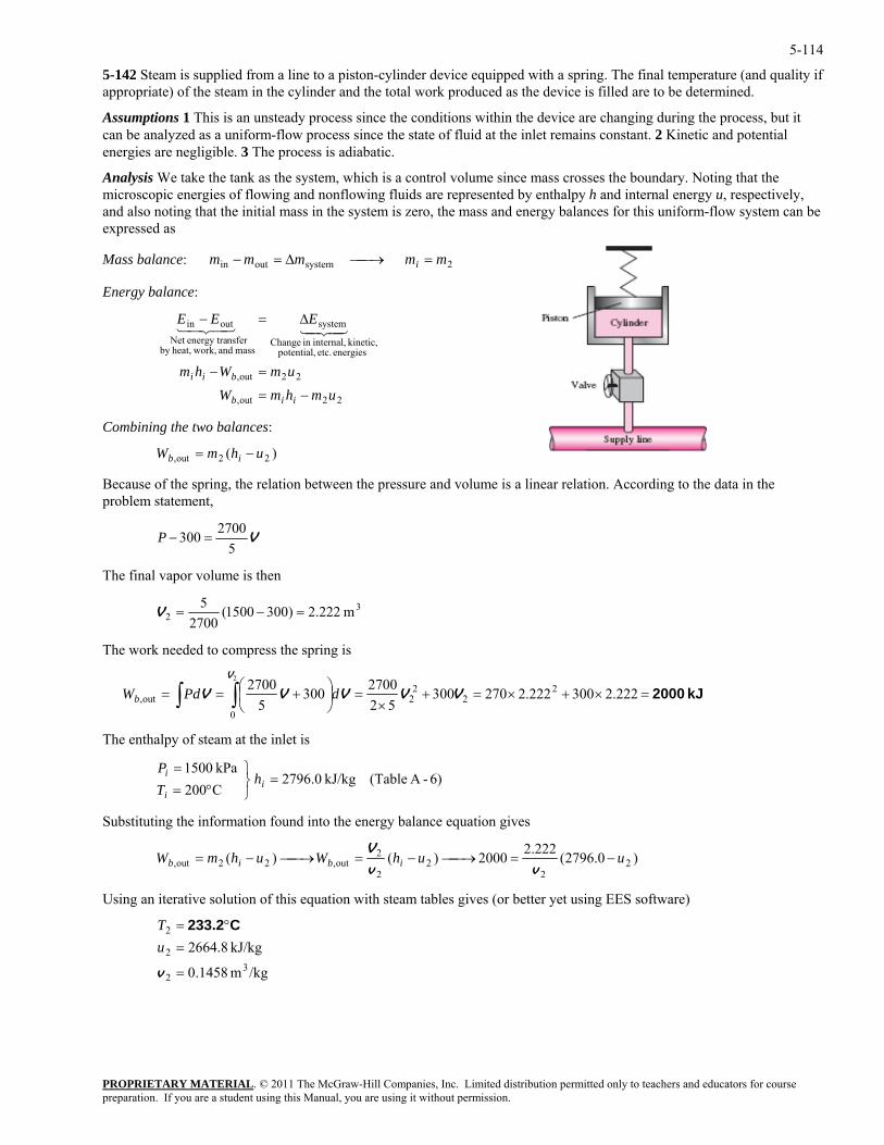
5-114
5-142 Steam is supplied from a line to a piston-cylinder device equipped with a spring. The final temperature (and quality if appropriate) of the steam in the cylinder and the total work produced as the device is filled are to be determined.
Assumptions 1 This is an unsteady process since the conditions within the device are changing during the process, but it can be analyzed as a uniform-flow process since the state of fluid at the inlet remains constant. 2 Kinetic and potential energies are negligible. 3 The process is adiabatic.
Analysis We take the tank as the system, which is a control volume since mass crosses the boundary. Noting that the microscopic energies of flowing and nonflowing fluids are represented by enthalpy h and internal energy u, respectively, and also noting that the initial mass in the system is zero, the mass and energy balances for this uniform-flow system can be expressed as
PROPRIETARY MATERIAL. © 2011 The McGraw-Hill Companies, Inc. Limited distribution permitted only to teachers and educators for course
out,
energies etc. potential,kinetic, internal,in ange
systemoutin
umWhm
EEE
bii =−
∆=−4342143421
ances:
Because of the spring, the relation between the pressure and volume is a linear relation. According to the data in the roblem statement,
Mass balance: 2systemoutin mmmmm i =⎯→⎯∆=−
Energy balance:
Ch
mass and work,heat,by nsferenergy traNet
2 2
22out, umhmW iib −=
Combining the two bal
)( 22out, uhmW ib −=
p
V5
300 =−P 2700
nal vapor volume is then
The fi
32 m 222.2)3001500(
27005
=−=V
The work needed to compress the spring is
kJ 2000=×+×=+×
=⎟⎠⎞⎛ 270027002V
⎜⎝
+= ∫∫ 222.2300222.227030052
3005
22
22out, VVVVV dPdWb
⎭⎬⎫
°==
ii
i hTP
Substituting the information found into the energy balance equation gives
=0
The enthalpy of steam at the inlet is
= 6)-A (Table kJ/kg 0.2796C200kPa 1500
)0.2796(222.22000)()( 22
22
2out,22out, uuhWuhmW ibib −=⎯→⎯−=⎯→⎯−=
vv
V
Using an iterative solution of this equation with steam tables gives (or better yet using EES software)
/kgm 1458.0
kJ/kg 8.26643
2
2
2
=
=°=
v
uT C233.2
preparation. If you are a student using this Manual, you are using it without permission.
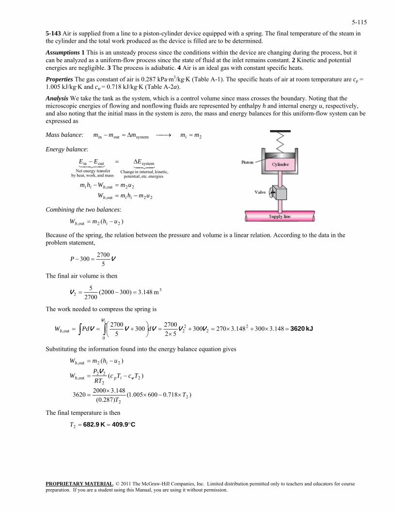
5-115
5-143 Air is supplied from a line to a piston-cylinder device equipped with a spring. The final temperature of the steam in the cylinder and the total work produced as the device is filled are to be determined.
Assumptions 1 This is an unsteady process since the conditions within the device are changing during the process, but it can be analyzed as a uniform-flow process since the state of fluid at the inlet remains constant. 2 Kinetic and potential energies are negligible. 3 The process is adiabatic. 4 Air is an ideal gas with constant specific heats.
Properties The gas constant of air is 0.287 kPa·m3/kg·K (Table A-1). The specific heats of air at room temperature are cp = 1.005 kJ/kg·K and cv = 0.718 kJ/kg·K (Table A-2a).
Analysis We take the tank as the system, which is a control volume since mass crosses the boundary. Noting that the microscopic energies of flowing and nonflowing fluids are represented by enthalpy h and internal energy u, respectively, and also noting that the initial mass in the system is zero, the mass and energy balances for this uniform-flow system can be expressed as
Mass balance: 2systemoutin mmmmm i =⎯→⎯∆=−
Energy balance:
22out,
22out,
energies etc. potential, kinetic, internal,in Change
system
mass and work,heat,by nsferenergy traNet
outin
umhmWumWhm
EEE
iib
bii
−=
=−
∆=−4342143421
Combining the two balances:
PROPRIETARY MATERIAL. © 2011 The McGraw-Hill Companies, Inc. Limited distribution permitted only to teachers and educators for course
g, the relation between the pressure and volume is a linear relation. According to the data in the problem statement,
)( 22out, uhmW ib −=
Because of the sprin
V5
2700300 =−P
he final a volume is then T ir
32 m 148.3)3002000(5
=−=V 2700
work needed to compress the spring is The
kJ 3620=×+×=+×
=⎟⎠
⎜⎝
+== ∫∫ 14.327030052
3005 2
22out, VVVVV dPdWb ⎞⎛ 148.3300827002700 2
0
2V
und into the energy balance equation gives
Substituting the information fo
)718.0600005.1()287.0(148.320003620
)(
)(
22
22
22out,
22out,
TT
TcTcRTP
W
uhmW
ipb
ib
×−××
=
−=
−=
vV
The final temperature is then
C409.9K 682.9 °==2T
preparation. If you are a student using this Manual, you are using it without permission.
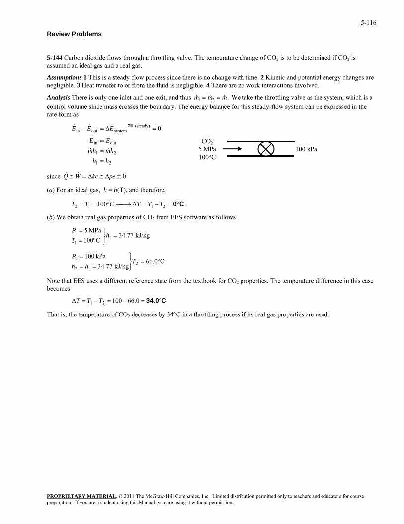
5-116
Review Problems
5-144 Carbon dioxide flows through a throttling valve. The temperature change of CO2 is to be determined if CO2 is assumed an ideal gas and a real gas.
Assumptions 1 This is a steady-flow process since there is no change with time. 2 Kinetic and potential energy changes are negligible. 3 Heat transfer to or from the fluid is negligible. 4 There are no work interactions involved.
PROPRIETARY MATERIAL. © 2011 The McGraw-Hill Companies, Inc. Limited distribution permitted only to teachers and educators for course
mAnalysis There is only one inlet and one exit, and thus & &m m1 2& = = . We take the throttling valve as the system, which iscontrol volume since mass crosses the boundary. The energy balance for this steady-flow system can be expressed in the rate
a
form as
= ≅ ≅∆ ∆ 0 .
100 TTTCTT
2
⎭
ote that E S uses a different reference state from the textbook for CO2 properties. The temperature difference in this case
That is, the temperature of CO2 decreases by 34°C in a throttling process if its real gas properties are used.
0
21
21
outin
(steady) 0systemoutin
hhhmhm
EE
EEE
==
=
=∆=−
&&
&&
&&&
CO25 MPa 100°C
100 kPa
since & ≅ &Q W ke pe
(a) For an ideal gas, h = h(T), and therefore,
C0°=−=∆⎯→⎯°== 2112
(b) We obtain real gas properties of CO from EES software as follows
kJ/kg 77.34C100
MPa 51
1
1 =⎭⎬⎫
°==
hTP
C0.66kJ/kg 77.34
kPa 1002
2 °=⎬⎫
===
Thh
P
12
N Ebecomes
C34.0°=−=−=∆ 0.6610021 TTT
preparation. If you are a student using this Manual, you are using it without permission.
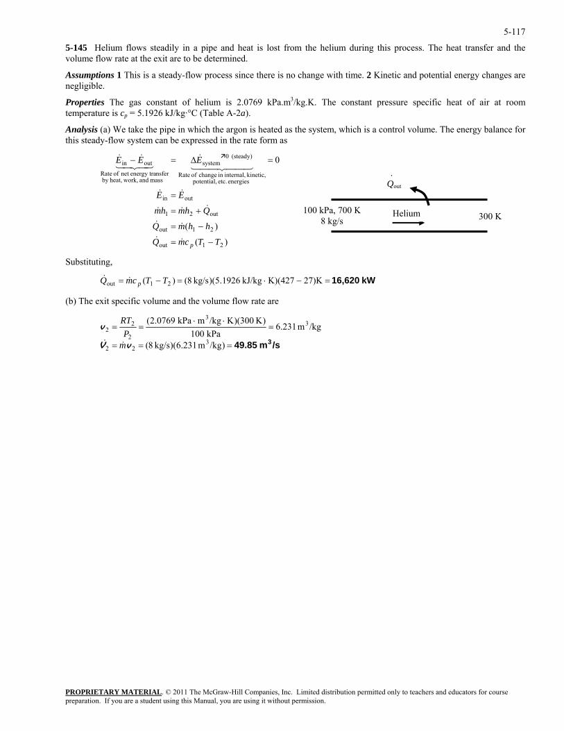
5-117
5-145 Helium flows steadily in a pipe and heat is lost from the helium during this process. The heat transfer and the volume flow rate at the exit are to be determined.
Assumptions 1 This is a steady-flow process since there is no change with time. 2 Kinetic and potential energy changes are negligible.
Properties The gas constant of helium is 2.0769 kPa.m3/kg.K. The constant pressure specific heat of air at room temperature is cp = 5.1926 kJ/kg·°C (Table A-2a).
Analysis (a) We take the pipe in which the argon is heated as the system, which is a control volume. The energy balance for this steady-flow system can be expressed in the rate form as
)(
)(
0
21out
21out
out21
outin
energies etc. potential, kinetic, internal,in change of Rate
(steady) 0system
mass and work,heat,by nsferenergy tranet of Rate
outin
TTcmQ
hhmQ
Qhmhm
EE
EEE
p −=
−=
+=
=
=∆=−
&&
&&
&&&
&&
44 344 21&
43421&&
300 K
Qout
.
100 kPa, 700 K8 kg/s
Helium
Substituting,
PROPRIETARY MATERIAL. © 2011 The McGraw-Hill Companies, Inc. Limited distribution permitted only to teachers and educators for course
ut TTcmQ p& o& kW 16,620=−⋅=−= 27)KK)(427kJ/kg 1926.5)(kg/s 8()( 21
(b) The exit specific volume and the volume flow rate are
/sm 49.85 3===
=⋅⋅
==
)/kgm 231.6)(kg/s 8(
/kgm 231.6kPa 100
)K 300)(K/kgmkPa .07692(
322
33
2
22
vV
v
mP
RT
&&
preparation. If you are a student using this Manual, you are using it without permission.
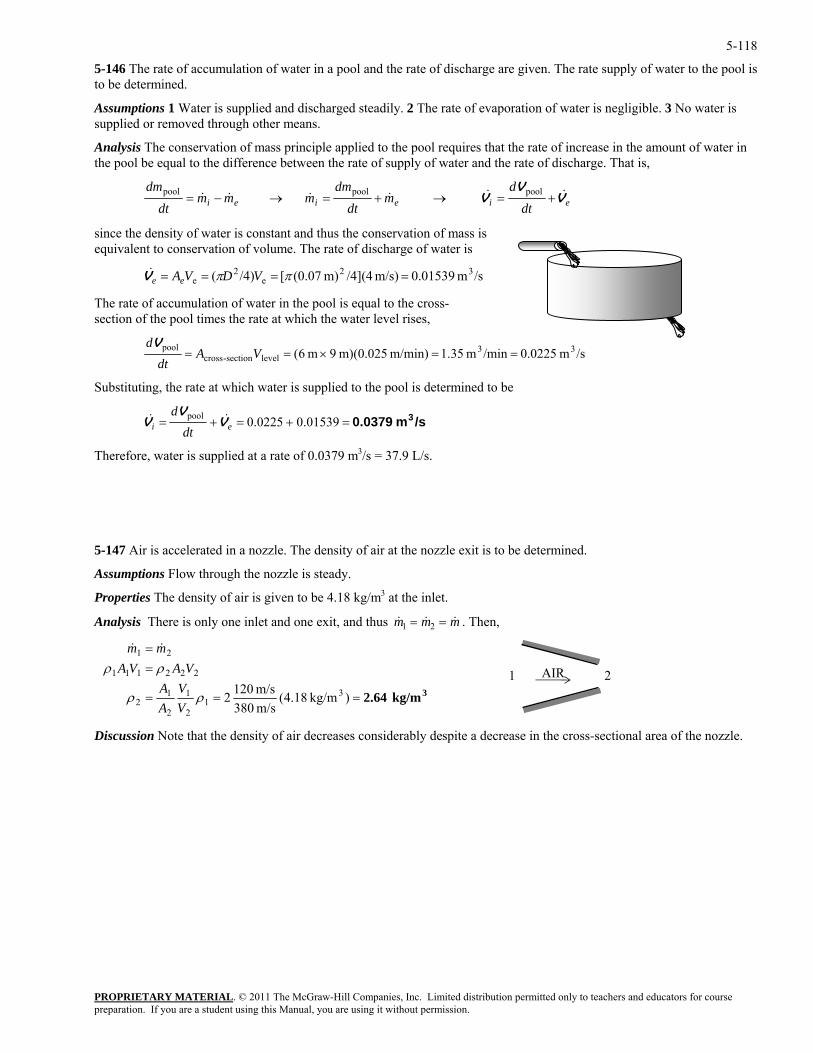
5-118
5-146 The rate of accumulation of water in a pool and the rate of discharge are given. The rate supply of water to the pool is to be determined.
Assumptions 1 Water is supplied and discharged steadily. 2 The rate of evaporation of water is negligible. 3 No water is supplied or removed through other means.
Analysis The conservation of mass principle applied to the pool requires that the rate of increase in the amount of water in the pool be equal to the difference between the rate of supply of water and the rate of discharge. That is,
eieiei dtdt
since the density of water is constant and thus the conservation of mass
dtd
mdm
mmmdm
VV
V &&&&&& +=→+=→−= poolpoolpool
is equivalent to conservation of volume. The rate of discharge of water is
3
s-ction of e pool times the rate at which the water level rises,
PROPRIETARY MATERIAL. © 2011 The McGraw-Hill Companies, Inc. Limited distribution permitted only to teachers and educators for course
/sm 01539.0m/s) /4](4m) (0.07[/4)( 2e
2e ==== ππ VDVAeeV&
The rate of accumulation of water in the pool is equal to the crosse th
/sm 0.0225 /min m 35.1m/min) m)(0.025 9m 6( 3pool ==×== VAdV 3
levelsection-crossdt
supplied to the pool is determined to be Substituting, the rate at which water is
/sm 0.0379 3=+=+= 01539.00225.0pooldV
VV && ei dt
herefore, water is supplied at a rate of 0.0379 m3/s = 37.9 L/s.
xit is to be determined.
Properties The density of air is given to be 4.18 kg/m3 at the inlet.
nalysis There is only one inlet and one exit, and thus
T
5-147 Air is accelerated in a nozzle. The density of air at the nozzle e
Assumptions Flow through the nozzle is steady.
A & & &m m m1 2= = . Then,
3kg/m 2.64=== ) kg/m18.4(m/s 1202 311 ρρVA
==
m/s 380122
2
222111
21
ρρ
VA
VAVAmm &&
Discussion Note that the density of air decreases considerably despite a decrease in the cross-sectional area of the nozzle.
AIR 1 2
preparation. If you are a student using this Manual, you are using it without permission.
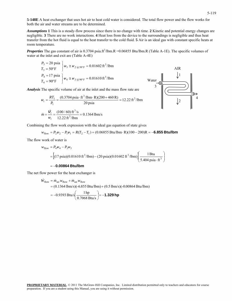
5-119
5-148E A heat exchanger that uses hot air to heat cold water is considered. The total flow power and the flow works for both the air and water streams are to be determined.
Assumptions 1 This is a steady-flow process since there is no change with time. 2 Kinetic and potential energy changes are negligible. 3 There are no work interactions. 4 Heat loss from the device to the surroundings is negligible and thus heat transfer from the hot fluid is equal to the heat transfer to the cold fluid. 5 Air is an ideal gas with constant specific heats at room temperature.
Properties The gas constant of air is 0.3704 psia.ft3/lbm.R =0.06855 Btu/lbm.R (Table A-1E). The specific volumes of water at the inlet and exit are (Table A-4E)
PROPRIETARY MATERIAL. © 2011 The McGraw-Hill Companies, Inc. Limited distribution permitted only to teachers and educators for course
psia 20
3F90@4
4
4
3
=≅⎭⎬⎫
°==
⎫=
°fTP
P
vv
Analysis The specific volume of air at the inlet and the mass flow rate are
/lbmft 01610.0F09psia 17
/lbmft 01602.0F05 F05@3
3=≅
⎭⎬°= °fT
vv
3
/lbmft 22.12R) 460R)(200/lbmftpsia 3704.0( 33
1 =+⋅⋅
==RT
v psia 201
1 P
lbm/s 1364.0/lbmft 12.22
/sft )60/100(1 ==V&
&m3
3
1=
v
ideal gas equation of state gives
2
1
4
3 Water
AIR
Combining the flow work expression with the
Btu/lbm 6.855−=−⋅=−=−= )R200R)(100Btu/lbm 06855.0()( 121122flow TTRPPw vv
The flow work of water is
[ ]Btu/lbm 0.00864−=
⎟⎟⎠
⎞⎜⎜⎝
⎛
⋅−=
−=
333
3344flow
ftpsia 5.404Btu 1/lbm)ft 01602.0(psia) 20(/lbm)ft 01610.0(psia) 17(
vv PPw
The net flow power for the heat exchanger is
hp 1.329−=⎟⎠
⎞⎜⎝
⎛−=
+=+=
Btu/s 0.7068hp 1
Btu/s 9393.0
Btu/lbm) 00864lbm/s)(-0. 5.0(Btu/lbm) 855lbm/s)(-6. 1364.0(flowairflowairflow wmwmW &&&
preparation. If you are a student using this Manual, you are using it without permission.
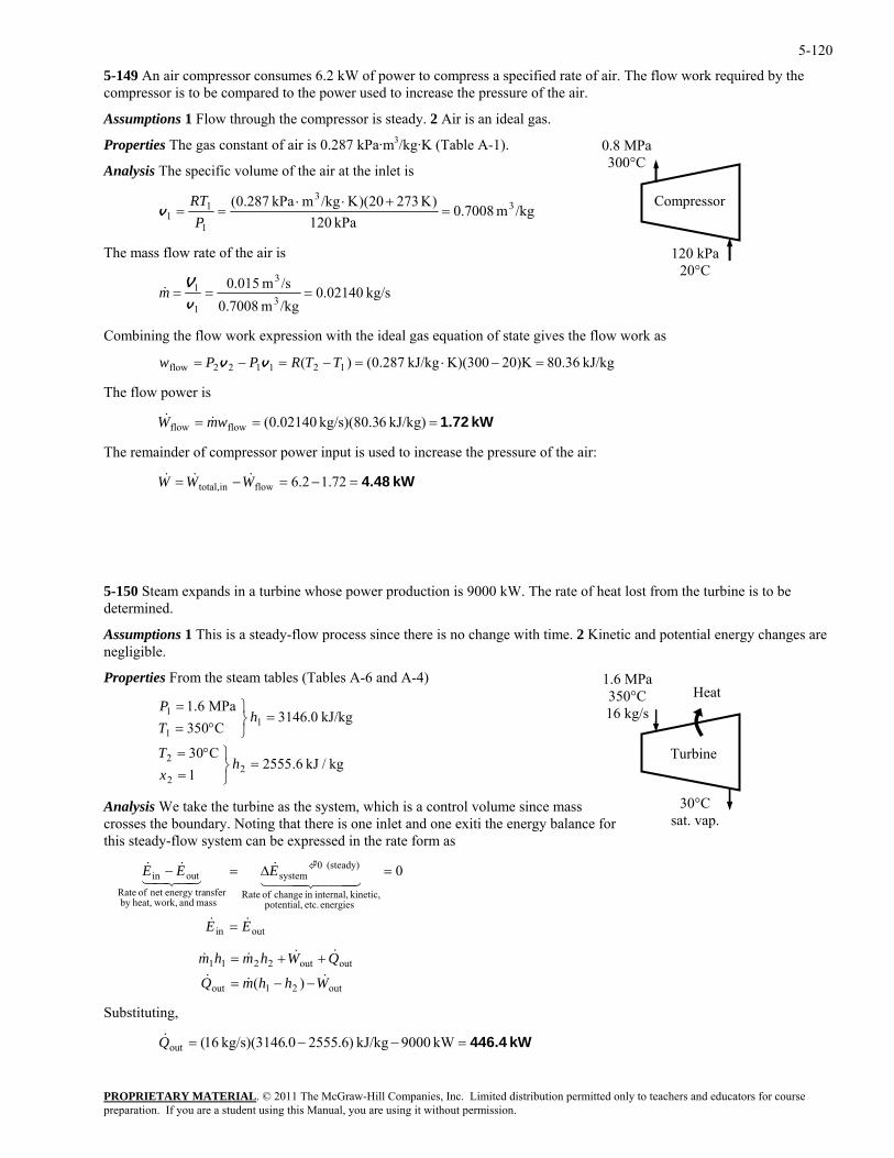
5-120
5-149 An air compressor consumes 6.2 kW of power to compress a specified rate of air. The flow work required by the compressor is to be compared to the power used to increase the pressure of the air.
Assumptions 1 Flow through the compressor is steady. 2 Air is an ideal gas.
Properties The gas constant of air is 0.287 kPa·m3/kg·K (Table A-1).
PROPRIETARY MATERIAL. © 2011 The McGraw-Hill Companies, Inc. Limited distribution permitted only to teachers and educators for course
Analysis The specific volume of the air at the inlet is
/kgm 7008.0kPa 120
)K 27320)(K/kgmkPa 0.287( 33
11 ==
Pv 1 =
+⋅⋅RT
he mass flow rate of the air is T
kg/s 02140.0/kgm 7008.0 3
1v /sm 015.0 3
1 ===V
m&
ombining the flow work expression with the ideal gas equation of state gives the flow work as
120 kPa20°C
0.8 MPa 300°C
Compressor
C
2flow kJ/kg 80.36)K20K)(300kJ/kg 287.0()( 12112 =−⋅=−=− TTRP vv
he flow power is
he remainder of compressor power input is used to increase the pressure of the air:
is no change with time. 2 Kinetic and potential energy changes are negligible.
Properties From the steam tables (Tables A-6 and A-4)
1
1
1 =⎭⎬⎫
°==
hTP
l volume since mass es the boundary. Noting that there is one inlet and one exiti the energy balance for
this steady-flow system can be expressed in the rate form as 0
system
mass dnsfer
0
EE
E
&&
444 3444 21&
43421
=
=∆=
Substituting,
= Pw
T
kW 1.72=== kJ/kg) 6kg/s)(80.3 02140.0(flowflow wmW &&
T
kW 4.48=−=−= 72.12.6flowintotal, WWW &&&
5-150 Steam expands in a turbine whose power production is 9000 kW. The rate of heat lost from the turbine is to be determined.
Assumptions 1 This is a steady-flow process since there
Turbine
1.6 MPa 350°C 16 kg/s
30°C sat. vap.
Heat
kJ/kg 3146.0C503
MPa 6.1
kg/kJ 6.25551
C032
2
2 =⎭⎬⎫
=°=
hxT
Analysis We take the turbine as the system, which is a controcross
outin
energies etc. potential, kinetic, internal,in change of Rate
(stead
an work,heat,by energy tranet of Rate
y)outin EE && −
out21out
outout2211
)( WhhmQ
QWhmhm&&&
&&&&
−−=
++=
kW 446.4=−−= kW 9000kJ/kg )6.2555.0kg/s)(3146 16(outQ&
preparation. If you are a student using this Manual, you are using it without permission.
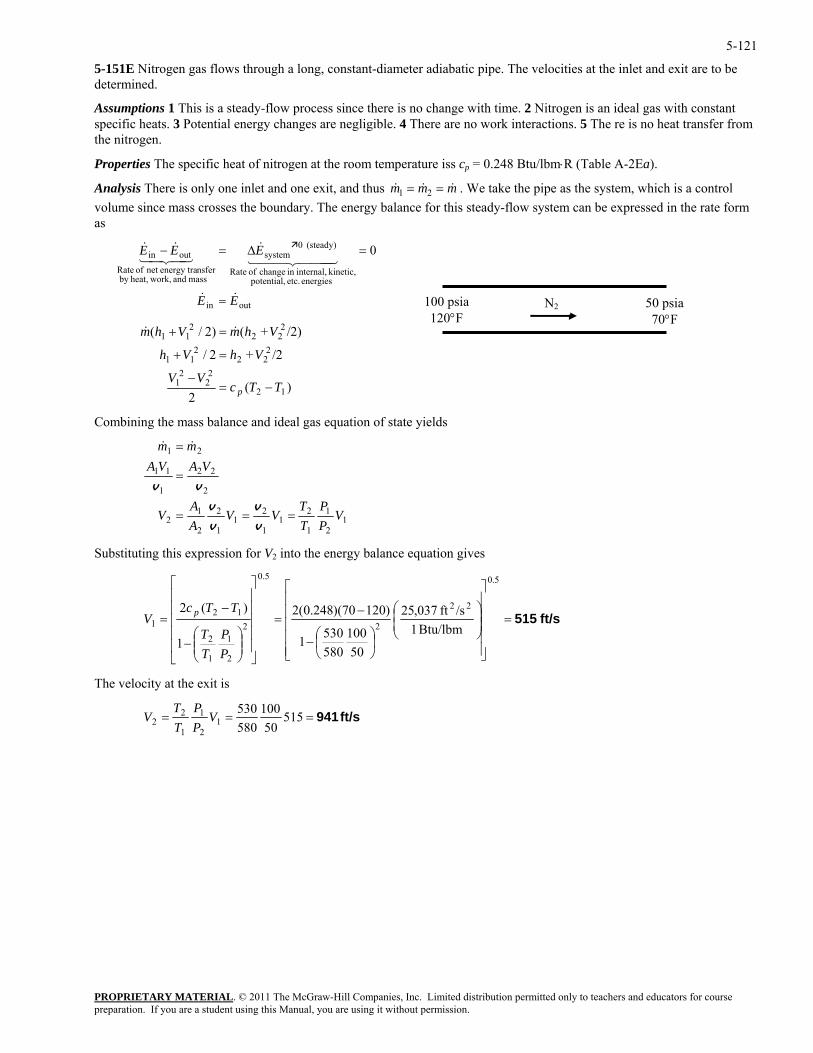
5-121
5-151E Nitrogen gas flows through a long, constant-diameter adiabatic pipe. The velocities at the inlet and exit are to be determined.
Assumptions 1 This is a steady-flow process since there is no change with time. 2 Nitrogen is an ideal gas with constant specific heats. 3 Potential energy changes are negligible. 4 There are no work interactions. 5 The re is no heat transfer from the nitrogen.
Properties The specific heat of nitrogen at the room temperature iss cp = 0.248 Btu/lbm⋅R (Table A-2Ea).
Analysis There is only one inlet and one exit, and thus mmm &&& == 21 . We take the pipe as the system, which is a control volume since mass crosses the boundary. The energy balance for this steady-flow system can be expressed in the rate form as
outin
energies etc. potential, kinetic, internal,in change of Rate
(steady) 0system
mass and work,heat,by nsferenergy tranet of Rate
outin 0
EE
EEE
&&
444 344 21&
43421&&
=
=∆=−
50 psia 70°F
100 psia1 20°F
N2
)(2
/2+2/
/2)+()2/(
12
222211 VhVh =+
21
22
222
211
TTcVV
VhmVhm
p −=−
=+ &&
Combining the mass balance and ideal gas equation of state yields
12
1
1
21
1
21
12
Substituting this expression for
212
2
22
1
11
21
VPP
TT
VVAA
V
VAVAmm
===
=
=
v
v
v
v
vv
&&
V2 into the energy balance equation gives
ft/s 515=
⎥⎥⎥⎥⎥
⎦
⎤
⎢⎢⎢⎢⎢
⎣
⎡
⎟⎟⎠
⎞⎜⎜⎝
⎛
⎟⎠⎞
⎜⎝⎛−
−=
⎥⎥⎥⎥⎥
⎦
⎤
⎢⎢⎢⎢⎢
⎣
⎡
⎟⎟⎠
⎞⎜⎜⎝
⎛−
−=
5.0
22
2
5.0
2
2
1
1
2
121 Btu/lbm 1
/sft 037,25
50100
5805301
)12070)(248.0(2
1
)(2
PP
TT
TTcV p
The velocity at the exit is
ft/s 941=== 51550
100580530
12
1
1
22 V
PP
TT
V
PROPRIETARY MATERIALpreparation. If you are a student using this Manual, you are using it without permission.
. © 2011 The McGraw-Hill Companies, Inc. Limited distribution permitted only to teachers and educators for course
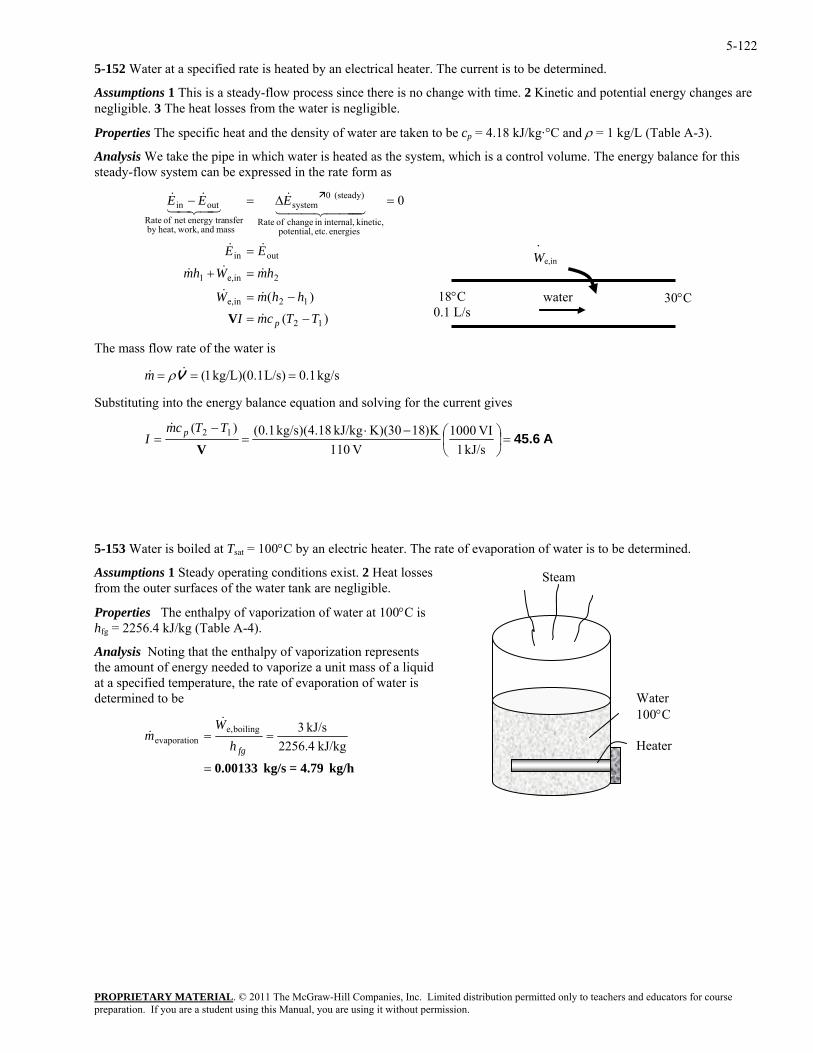
5-122
5-152 Water at a specified rate is heated by an electrical heater. The current is to be determined.
Assumptions 1 This is a steady-flow process since there is no change with time. 2 Kinetic and potential energy changes are negligible. 3 The heat losses from the water is negligible.
Properties The specific heat and the density of water are taken to be cp = 4.18 kJ/kg·°C and ρ = 1 kg/L (Table A-3).
Analysis We take the pipe in which water is heated as the system, which is a control volume. The energy balance for this steady-flow system can be expressed in the rate form as
)()(
0
12
12ine,
2ine,1
outin
energies etc. potential, kinetic, internal,in change of Rate
(steady) 0system
mass and work,heat,by nsferenergy tranet of Rate
outin
TTcmIhhmW
hmWhm
EE
EEE
p −=
−=
=+
=
=∆=−
&
&&
&&&
&&
444 344 21&
43421&&
V
30°C 18°C 0.1 L/s
water
We,in
.
The mass flow rate of the water is
kg/s 1.0L/s) kg/L)(0.1 1( === V&& ρm
Substituting into the energy balance equation and solving for the current gives
A45.6=⎟⎠⎞
⎜⎝⎛−⋅
=−
=kJ/s 1
VI 1000V 110
K)1830(K)kJ/kg 18.4)(kg/s 1.0()( 12
VTTcm
I p&
5-153 Water is boiled at Tsat = 100°C by an electric heater. The rate of evaporation of water is to be determined.
Assumptions 1 Steady operating conditions exist. 2 Heat losses from the outer surfaces of the water tank are negligible.
Steam
Properties The enthalpy of vaporization of water at 100°C is hfg = 2256.4 kJ/kg (Table A-4).
Analysis Noting that the enthalpy of vaporization represents the amount of energy needed to vaporize a unit mass of a liquid at a specified temperature, the rate of evaporation of water is determined to be Water
100°C Heater
kg/h 4.79=kg/s 0.00133=
==kJ/kg 2256.4
kJ/s 3boilinge,nevaporatio
fghW
m&
&
PROPRIETARY MATERIALpreparation. If you are a student using this Manual, you are using it without permission.
. © 2011 The McGraw-Hill Companies, Inc. Limited distribution permitted only to teachers and educators for course
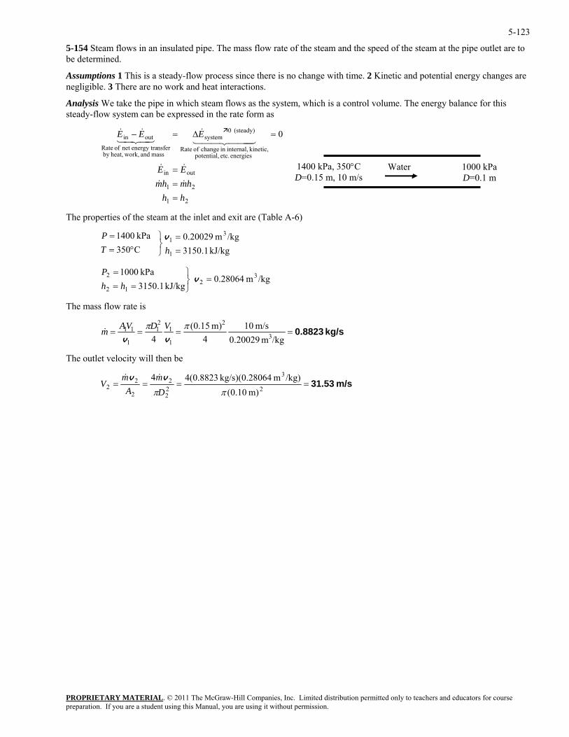
5-123
5-154 Steam flows in an insulated pipe. The mass flow rate of the steam and the speed of the steam at the pipe outlet are to be determined.
Assumptions 1 This is a steady-flow process since there is no change with time. 2 Kinetic and potential energy changes are negligible. 3 There are no work and heat interactions.
Analysis We take the pipe in which steam flows as the system, which is a control volume. The energy balance for this steady-flow system can be expressed in the rate form as
21
21
outin
energies etc. potential, kinetic, internal,in change of Rate
(steady) 0system
mass and work,heat,by nsferenergy tranet of Rate
outin 0
hhhmhm
EE
EEE
===
=∆=−
&&
&&
444 344 21&
43421&&
1000 kPa D=0.1 m
1400 kPa, 350°C D=0.15 m, 10 m/s
Water
The properties of the steam at the inlet and exit are (Table A-6)
PROPRIETARY MATERIAL. © 2011 The McGraw-Hill Companies, Inc. Limited distribution permitted only to teachers and educators for course
hT
P v
0 kPa 1000 3
22 =
⎭⎬⎫=
v P
he mass flow rate is
kJ/kg 1.3150/kgm 20029.0
C350 kPa 1400
1
31
==
⎭⎬⎫
°==
31512 == hh
/kgm 28064.0kJ/kg 1.
T
kg/s 0.8823====/kgm 0.20029
m/s 104
m) 15.0(4 3
2
1
12 ππ VDVA 1
1
11
vvm&
The outlet velocity will then be
m/s 31.53====2
3
22
2
2
22
m) 10.0(/kg)m 064kg/s)(0.28 8823.0(44
ππDm
Am
Vvv &&
preparation. If you are a student using this Manual, you are using it without permission.
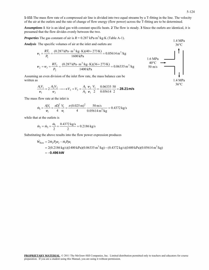
5-124
5-155 The mass flow rate of a compressed air line is divided into two equal streams by a T-fitting in the line. The velocity of the air at the outlets and the rate of change of flow energy (flow power) across the T-fitting are to be determined.
Assumptions 1 Air is an ideal gas with constant specific heats. 2 The flow is steady. 3 Since the outlets are identical, it is presumed that the flow divides evenly between the two.
Properties The gas constant of air is R = 0.287 kPa⋅m3/kg⋅K (Table A-1).
1.4 MPa36°C
1.4 MPa36°C Analysis The specific volumes of air at the inlet and outlets are
/kgm 05614.0kPa 1600
K) 273K)(40/kgmkPa 287.0( 33
1
11 =
+⋅⋅==
PRT
v 1.6 MPa
40°C 50 m/s /kgm 06335.0
kPa 1400232 ====
Pvv
ing an even division of the inle
K) 273K)(36/kgmkPa 287.0( 33
2 +⋅⋅RT
t flow rate, the mass balance can be ritten as
Assumw
m/s 28.21====⎯→⎯=2
500.05614
06335.02
2 1
1
2
2
132
2
2211 VAVA
1
VAA
VVv
v
vv
The mass flow rate at the inlet is
kg/s 0.4372/kgm 0.05614
m/s 504
m) 025.0(4 3
2
1
12111 πDVA
1====
πvvVm&
1
while that at the outlets is
kg/s 0.21862
kg/s 4372.02
132 ====
mmm&
&&
Substituting the above results into the flow power expression produces
kW 0.496−=
−=
−=
/kg)m 14kPa)(0.056 1600)(kg/s 0.4372(/kg)m 35kPa)(0.063 1400)(kg/s 0.2186(2
233
111222flow vv PmPmW &&&
PROPRIETARY MATERIALpreparation. If you are a student using this Manual, you are using it without permission.
. © 2011 The McGraw-Hill Companies, Inc. Limited distribution permitted only to teachers and educators for course
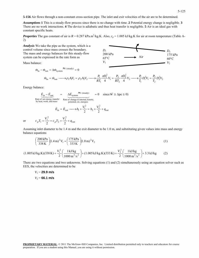
5-125
5-156 Air flows through a non-constant cross-section pipe. The inlet and exit velocities of the air are to be determined.
Assumptions 1 This is a steady-flow process since there is no change with time. 2 Potential energy change is negligible. 3 There are no work interactions. 4 The device is adiabatic and thus heat transfer is negligible. 5 Air is an ideal gas with constant specific heats.
Properties The gas constant of air is R = 0.287 kPa.m3/kg.K. Also, cp = 1.005 kJ/kg.K for air at room temperature (Table A-2)
PROPRIETARY MATERIAL. © 2011 The McGraw-Hill Companies, Inc. Limited distribution permitted only to teachers and educators for course
Analysis We take the pipe as the system, which is a control volume since mass crosses the boundary. The mass and energy balances for this steady-flow system can be expressed in the rate form as
Mass balance:
222
2
21
21
1
12
22
2
21
21
1
1222111outin
(steady) 0systemoutin&
44
0
VDTPVD
TPVD
RTPVD
RTPVAVAmm
mmm
=⎯→⎯=⎯→⎯=⎯→⎯=
=∆=−
ππρρ&&
&&
Energy balance:
D1200 kPa 65°C V1
q
Air
D2175 kPa 60°C V2
out2
21
1outin 22qhhEE ++=+⎯→⎯= &&
22
energies etc. potential, kinetic, internal,in change of Rate
(steady) 0system
mass and work,heat,by nsferenergy tranet of Rate
outin 0)pe since 0
VV
WEEE ≅∆≅=∆=− &44 344 21
&43421&&
r out
22
2
21
1 22q
VTc
VTc pp ++=+ o
Assuming inlet diameter to be 1.4 m and the exit diameter to be 1.0 m, and substituting given values into mass and energy balance equations
22
12
K 333kPa 175)m 1.4(
K 338kPa 200 V ⎞
⎜⎝⎛=⎟
⎠⎞
⎜⎛ )m 1.0( V⎟
⎠ (1)
⎝
kJ/kg 3.3/sm 1000
kJ/kg 12
K) 33kJ/kg.K)(3 (1.005/sm 1000
kJ/kg 12
K) 38J/kg.K)(3 +k (1.00522
22
22
21 +⎟
⎠
⎞⎜⎝
⎛+=⎟⎠
⎞⎜⎝
⎛ VV (2)
There are two equations and two unknowns. Solving equations (1) and (2) simultaneously using an equation solver such as EES, the velocities are determined to be
V1 = 29.9 m/s
V2 = 66.1 m/s
preparation. If you are a student using this Manual, you are using it without permission.
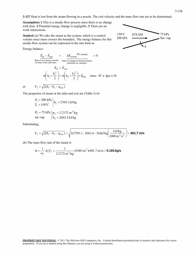
5-126
5-157 Heat is lost from the steam flowing in a nozzle. The exit velocity and the mass flow rate are to be determined.
Assumptions 1 This is a steady-flow process since there is no change with time. 2 Potential energy change is negligible. 3 There are no work interactions.
150°C 200 kPa
STEAM
q
75 kPa Sat. vap.
Analysis (a) We take the steam as the system, which is a control volume since mass crosses the boundary. The energy balance for this steady-flow system can be expressed in the rate form as
Energy balance:
0)pe since 22
0
out
22
2
21
1
outin
energies etc. potential, kinetic, internal,in change of Rate
(steady) 0system
mass and work,heat,by nsferenergy tranet of Rate
outin
≅∆≅+⎟⎟⎠
⎞⎜⎜⎝
⎛+=⎟
⎟⎠
⎞⎜⎜⎝
⎛+
=
=∆=−
WQVhmVhm
EE
EEE
&&&&
&&
44 344 21&
43421&&
or )(2 out212 qhhV −−=
ap.kPa 75
2
32
==
⎭⎬⎫
hv
ubstituting,
The properties of steam at the inlet and exit are (Table A-6)
kJ/kg 1.2769C150kPa 002
11
1 =⎭⎬⎫
°==
hTP
vsat.
2 =PkJ/kg 4.2662
/kgm 2172.2
S
m/s 401.7=⎟⎠
⎞⎜⎝
⎛−− =−−= out212 (2)(2 qhhV
22 /sm 1000kJ/kg 1
kJ/kg)264.26621.2769
(b) The mass flow rate of the steam is
kg/s 0.181=== m/s) )(401.7m (0.001/kgm 2.2172
11 2322
2VAm
v&
PROPRIETARY MATERIALpreparation. If you are a student using this Manual, you are using it without permission.
. © 2011 The McGraw-Hill Companies, Inc. Limited distribution permitted only to teachers and educators for course
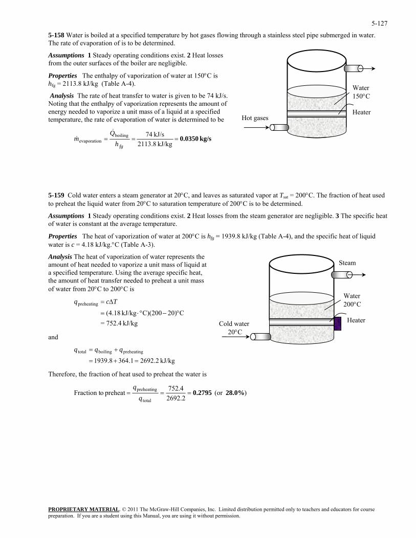
5-127
5-158 Water is boiled at a specified temperature by hot gases flowing through a stainless steel pipe submerged in water. The rate of evaporation of is to be determined.
Water 150°C Heater
Hot gases
Assumptions 1 Steady operating conditions exist. 2 Heat losses from the outer surfaces of the boiler are negligible.
Properties The enthalpy of vaporization of water at 150°C is hfg = 2113.8 kJ/kg (Table A-4).
Analysis The rate of heat transfer to water is given to be 74 kJ/s. Noting that the enthalpy of vaporization represents the amount of energy needed to vaporize a unit mass of a liquid at a specified temperature, the rate of evaporation of water is determined to be
kg/s 0.0350===kJ/kg 2113.8
kJ/s 74boilingnevaporatio
fghQ
m&
&
5-159 Cold water enters a steam generator at 20°C, and leaves as saturated vapor at Tsat = 200°C. The fraction of heat used to preheat the liquid water from 20°C to saturation temperature of 200°C is to be determined.
Assumptions 1 Steady operating conditions exist. 2 Heat losses from the steam generator are negligible. 3 The specific heat of water is constant at the average temperature.
Properties The heat of vaporization of water at 200°C is hfg = 1939.8 kJ/kg (Table A-4), and the specific heat of liquid water is c = 4.18 kJ/kg.°C (Table A-3).
Analysis The heat of vaporization of water represents the amount of heat needed to vaporize a unit mass of liquid at a specified temperature. Using the average specific heat, the amount of heat transfer needed to preheat a unit mass of water from 20°C to 200°C is
Water 200°C
Heater Cold water 20°C
Steam
kJ/kg 752.4=C20)C)(200kJ/kg 18.4(
preheating
°−°⋅=
∆= Tcq
and
=+=
herefore, the fraction of heat used to preheat the water is
kJ/kg 2.26921.3648.1939preheatingboilingtotal += qqq
T
)(or 2692.2
4.752preheat oFraction ttotal
preheating 28.0% 0.2795===q
q
PROPRIETARY MATERIALpreparation. If you are a student using this Manual, you are using it without permission.
. © 2011 The McGraw-Hill Companies, Inc. Limited distribution permitted only to teachers and educators for course
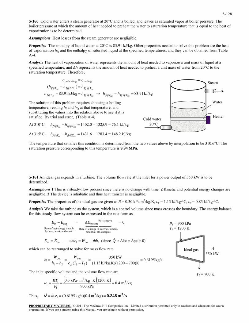
5-128
5-160 Cold water enters a steam generator at 20°C and is boiled, and leaves as saturated vapor at boiler pressure. The boiler pressure at which the amount of heat needed to preheat the water to saturation temperature that is equal to the heat of vaporization is to be determined.
Assumptions Heat losses from the steam generator are negligible.
Properties The enthalpy of liquid water at 20°C is 83.91 kJ/kg. Other properties needed to solve this problem are the heat of vaporization hfg and the enthalpy of saturated liquid at the specified temperatures, and they can be obtained from Table A-4.
Analysis The heat of vaporization of water represents the amount of heat needed to vaporize a unit mass of liquid at a specified temperature, and ∆h represents the amount of heat needed to preheat a unit mass of water from 20°C to the saturation temperature. Therefore,
kJ/kg 91.83 kJ/kg 91.83
)(
satsatsatsat
satsat
@@@@
@C@20@
boilingpreheating
=−→=−
=−
=
°
TfgTfTfgTf
TfgfTf
hhhh
hhh
PROPRIETARY MATERIAL. © 2011 The McGraw-Hill Companies, Inc. Limited distribution permitted only to teachers and educators for course
.9 = 76.1 kJ/kg
=
≅∆=∆≅+=⎯→⎯= QhmWhmEE &&&&&&
Water Heater Cold water
20°C
Steam
The solution of this problem requires choosing a boiling temperature, reading hf and hfg at that temperature, and substituting the values into the relation above to see if it is satisfied. By trial and error, (Table A-4)
At 310°C: hf T fg T@ sat sat− =@ 1402.0 – 1325h
At 315°C: h h 1431.6 – 1283.4 = 148.2 kJ/kg f T fg T@ sat sat− @
The temperature that satisfies this condition is determined from the two values above by interpolation to be 310.6°C. The saturation pressure corresponding to this temperature is 9.94 MPa.
5-161 An ideal gas expands in a turbine. The volume flow rate at the inlet for a power output of 350 kW is to be determined.
Assumptions 1 This is a steady-flow process since there is no change with time. 2 Kinetic and potential energy changes are negligible. 3 The device is adiabatic and thus heat transfer is negligible.
Properties The properties of the ideal gas are given as R = 0.30 kPa.m3/kg.K, cp = 1.13 kJ/kg·°C, cv = 0.83 kJ/kg·°C.
Analysis We take the turbine as the system, which is a control volume since mass crosses the boundary. The energy balance for this steady-flow system can be expressed in the rate form as
0
energies etc. potential, kinetic, internal,in change of Rate
(steady) 0system
mass and work,heat,by nsferenergy tranet of Rate
outin =∆=−44 344 21
&43421&& EEE P1 = 900 kPa
T1 = 1200 K
350 kWIdeal gas
0)peke (since 2out1outin
which can be rearranged to solve for mass flow rate
kg/s 6195.0700)K200kJ/kg.K)(1 (1.13
kW 350)( 21
out
21
out =−
=−
=−
=TTc
Whh
Wm
p
&&&
The inl peet s cific volume and the volume flow rate are
T2 = 700 K( )( ) /kgm 4.0
kPa 900K 1200K/kgmkPa 0.3 3
3
1
11 =
⋅⋅==
PRT
v
/sm 0.248 3=== /kg)m kg/s)(0.4 6195.0( 31vV m&& Thus,
preparation. If you are a student using this Manual, you are using it without permission.
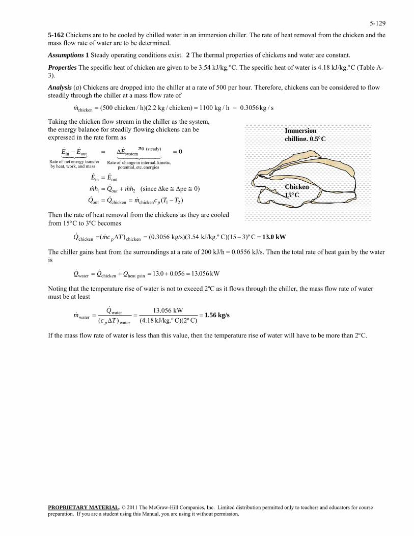
5-129
5-162 Chickens are to be cooled by chilled water in an immersion chiller. The rate of heat removal from the chicken and the mass flow rate of water are to be determined.
Assumptions 1 Steady operating conditions exist. 2 The thermal properties of chickens and water are constant.
Properties The specific heat of chicken are given to be 3.54 kJ/kg.°C. The specific heat of water is 4.18 kJ/kg.°C (Table A-3).
Analysis (a) Chickens are dropped into the chiller at a rate of 500 per hour. Therefore, chickens can be considered to flow steadily through the chiller at a mass flow rate of
&mchicken (500 chicken / h)(2.2 kg / chicken) 1100 kg / h = 0.3056 kg / s= =
Taking the chicken flow stream in the chiller as the system, the energy balance for steadily flowing chickens can be expressed in the rate form as
PROPRIETARY MATERIAL. © 2011 The McGraw-Hill Companies, Inc. Limited distribution permitted only to teachers and educators for course
)( 21chickenchickenout TTcmQQ p −== &&&
0)peke (since
0
21
outin
energies etc. ntial,
(steady) 0systemoutin
hmQhm
EE
EEE
out ≅∆≅∆+=
=
=∆=−
&&&
&&&
hen the r e of heat removal from the chickens as they are cooled om 15°C to 3ºC becomes
=−=∆= Tcm p&
he chiller gains heat from the surroundings at a rate of 200 kJ/h = 0.0556 kJ/s. Then the total rate of heat gain by the water
oting that the temperature rise of water is not to exceed 2ºC as it flows through the chiller, the mass flow rate of water must be at least
Chicken 15°C
Immersion chilling, 0.5°C
pote kinetic, internal,in change of Rate
mass and work,heat,by nsferenergy tranet of Rate
&&
44 344 2143421
T atfr
chickenQ& kW13.0 C3)ºC)(15kJ/kg.º kg/s)(3.54 (0.3056)( chicken
Tis
& & & . . .Q Q Qwater chicken heat gain kW= + = + =13 0 0 056 13 056
N
kg/s 1.56==∆
=C)C)(2ºkJ/kg.º (4.18
kW 13.056)( water
waterwater Tc
Qm
p
&&
If the mass flow rate of water is less than this value, then the temperature rise of water will have to be more than 2°C.
preparation. If you are a student using this Manual, you are using it without permission.
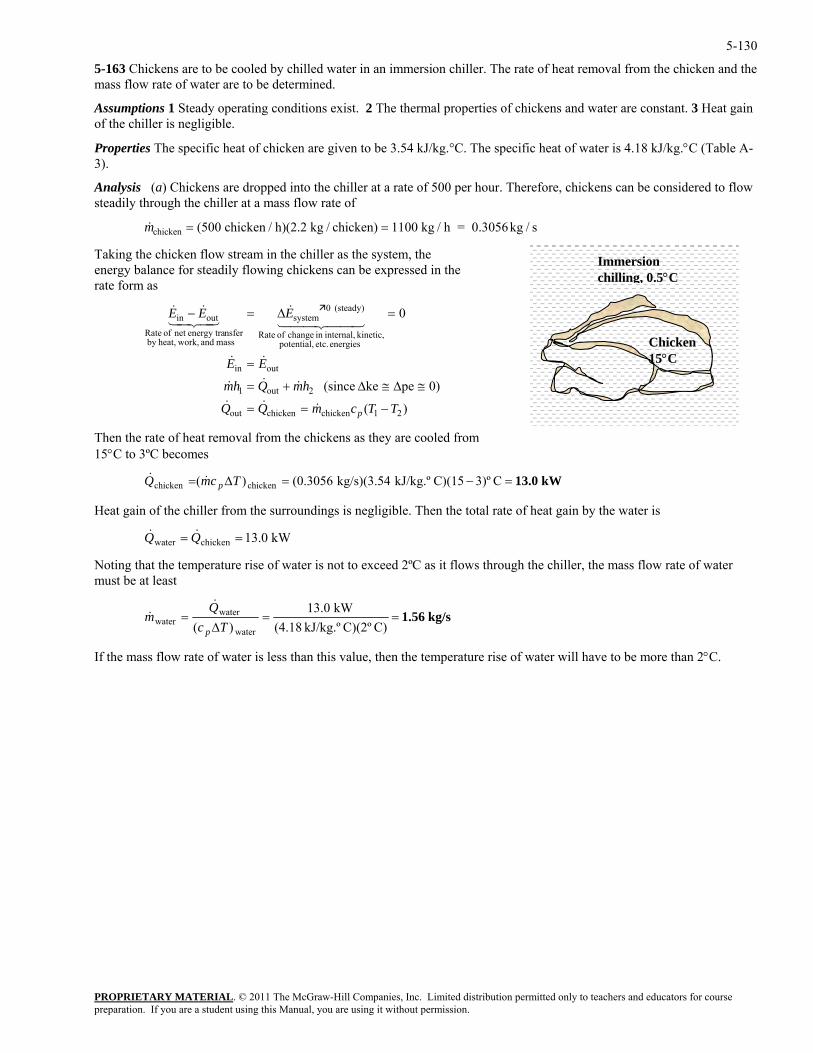
5-130
5-163 Chickens are to be cooled by chilled water in an immersion chiller. The rate of heat removal from the chicken and the mass flow rate of water are to be determined.
Assumptions 1 Steady operating conditions exist. 2 The thermal properties of chickens and water are constant. 3 Heat gain of the chiller is negligible.
Properties The specific heat of chicken are given to be 3.54 kJ/kg.°C. The specific heat of water is 4.18 kJ/kg.°C (Table A-3).
Analysis (a) Chickens are dropped into the chiller at a rate of 500 per hour. Therefore, chickens can be considered to flow steadily through the chiller at a mass flow rate of
PROPRIETARY MATERIAL. © 2011 The McGraw-Hill Companies, Inc. Limited distribution permitted only to teachers and educators for course
icken (500 chicken / h)(2.2 kg / chicken) 1100 kg / h = 0.3056 kg / s=&mch =
=−=∆= TcmQ &
Heat gain of the chiller from the surroundings is negligible. Then the total rate of heat gain by the water is
== QQ &&
mperature rise of water is not to exceed 2ºC as it flows through the chiller, the mass flow rate of water ust be at least
Taking the chicken flow stream in the chiller as the system, the energy balance for steadily flowing chickens can be expressed in the rate form as
Chicken 15°C
Immersion chilling, 0.5°C
)(
0)peke (since
0
21chickenchickenout
2out1
outin
energies etc. potential, kinetic, internal,in change of Rate
(steady) 0system
mass and work,heat,by nsferenergy tranet of Rate
outin
TTcmQQ
hmQhm
EE
EEE
p −==
≅∆≅∆+=
=
=∆=−
&&&
&&&
&&
44 344 21&
43421&&
Then the rate of heat removal from the chickens as they are cooled from 15°C to 3ºC becomes
& kW13.0 C3)ºC)(15kJ/kg.º kg/s)(3.54 (0.3056)( chickenchicken p
kW 0.13chickenwater
Noting that the tem
kg/s 1.56===kW 13.0water
waterQ
m&
& ∆ C)C)(2ºkJ/kg.º (4.18)( waterTc p
If the mass flow rate of water is less than this value, then the temperature rise of water will have to be more than 2°C.
preparation. If you are a student using this Manual, you are using it without permission.
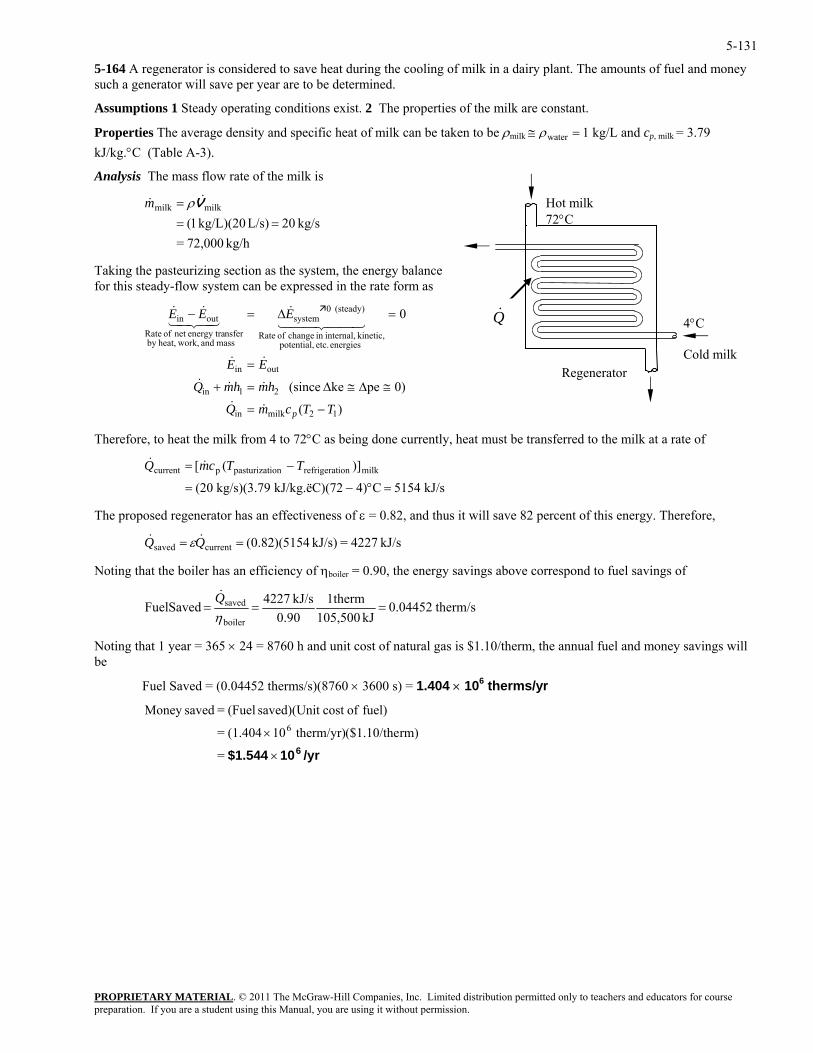
5-131
5-164 A regenerator is considered to save heat during the cooling of milk in a dairy plant. The amounts of fuel and money such a generator will save per year are to be determined.
Assumptions 1 Steady operating conditions exist. 2 The properties of the milk are constant.
Properties The average density and specific heat of milk can be taken to be ρmilk ≅ =ρwater 1 kg/L and cp, milk = 3.79 kJ/kg.°C (Table A-3).
Analysis The mass flow rate of the milk is
PROPRIETARY MATERIAL. © 2011 The McGraw-Hill Companies, Inc. Limited distribution permitted only to teachers and educators for course
kg/h 72,000=kg/s 20L/s) kg/L)(20 1( ==
milkmilk& = V&ρm
Taking the pasteurizing section as the system, the energy balance for this steady-flow system can be expressed in the rate form as
0
12milkin
outin
energies etc. potential, kinetic, internal,in change of Rate
(steady) 0system
mass and work,heat,by nsferenergy tranet of Rate
outin
TTcmQ
EE
EEE
p −=
=
=∆=−
&&
&&
44 344 21&
43421&&
−= TTcmQ &&
he propo d regenerator has an effectiveness of ε = 0.82, and thus it will save 82 percent of this energy. Therefore,
η
4°C Cold milk
Hot milk 72°C
Q&
Regenerator 0)peke (since 21in hmhmQ ≅∆≅∆=+ &&&
)(
Therefore, to heat the milk from 4 to 72°C as being done currently, heat must be transferred to the milk at a rate of
)]([ milkionrefrigerationpasturizatpcurrent
kJ/s 5154C4)72kJ/kg.ëC)( kg/s)(3.79 (20 =°−=
T se
kJ/s 4227=kJ/s) 5154)(82.0(currentsaved == QQ && ε
Noting that the boiler has an efficiency of boiler = 0.90, the energy savings above correspond to fuel savings of
therm/s 0.04452kJ 105,500
1therm0.90
kJ/s 4227SavedFuelboiler
saved ===ηQ&
Noting that 1 year = 365 × 24 = 8760 h and unit cost of natural gas is $1.10/therm, the annual fuel and money savings will be
Fuel Saved = (0.04452 therms/s)(8760 × 3600 s) = 1.404 × 10⁶ therms/yr
/yr10$1.544 6×
×
=
rm)($1.10/the therm/yr)10(1.404=
fuel) ofcost t saved)(Uni (Fuel= savedMoney 6
preparation. If you are a student using this Manual, you are using it without permission.
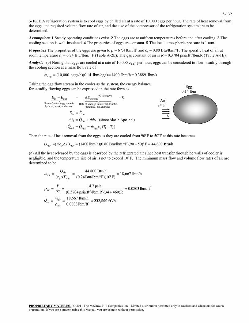
5-132
5-165E A refrigeration system is to cool eggs by chilled air at a rate of 10,000 eggs per hour. The rate of heat removal from the eggs, the required volume flow rate of air, and the size of the compressor of the refrigeration system are to be determined.
Assumptions 1 Steady operating conditions exist. 2 The eggs are at uniform temperatures before and after cooling. 3 The cooling section is well-insulated. 4 The properties of eggs are constant. 5 The local atmospheric pressure is 1 atm.
Properties The properties of the eggs are given to ρ = 67.4 lbm/ft3 and cp = 0.80 Btu/lbm.°F. The specific heat of air at room temperature cp = 0.24 Btu/lbm. °F (Table A-2E). The gas constant of air is R = 0.3704 psia.ft3/lbm.R (Table A-1E).
Analysis (a) Noting that eggs are cooled at a rate of 10,000 eggs per hour, eggs can be considered to flow steadily through the cooling section at a mass flow rate of
lbm/s 0.3889 =lbm/h 1400lbm/egg) 14eggs/h)(0. (10,000egg ==m
=°−°=∆= TcmQ &
temperature rise of air is not to exceed 10°F. The minimum mass flow and volume flow rates of air are determined to be
&
Taking the egg flow stream in the cooler as the system, the energy balance for steadily flowing eggs can be expressed in the rate form as Egg
0.14 lbm
)(
0)peke (since
0
21eggeggout
2out1
outin
energies etc. potential, kinetic, internal,in change of Rate
(steady) 0system
mass and work,heat,by nsferenergy tranet of Rate
outin
TTcmQQ
hmQhm
EE
EEE
p −==
≅∆≅∆+=
=
=∆=−
&&&
&&&
&&
44 344 21&
43421&&
Air34°F
Then the rate of heat removal from the eggs as they are cooled from 90°F to 50ºF at this rate becomes
PROPRIETARY MATERIAL. © 2011 The McGraw-Hill Companies, Inc. Limited distribution permitted only to teachers and educators for course
Btu/h44,800 F)50F)(90Btu/lbm. 0lbm/h)(0.8 (1400)( eggegg p
(b) All the heat released by the eggs is absorbed by the refrigerated air since heat transfer through he walls of cooler is negligible, and the
&
lbm/h 18,667F)F)(10Btu/lbm.(0.24
Btu/h 44,800)( air
airair =
°°=
∆=
TcQm
p
&&
ft³/h232,500 lbm/ft³0.0803lbm/h 18,667
lbm/ft 0803.0460)R/lbm.R)(34psia.ft (0.3704
psia 7.14
air
airair
33air
===
=+
==
ρ
ρ
mRTP
&&V
preparation. If you are a student using this Manual, you are using it without permission.
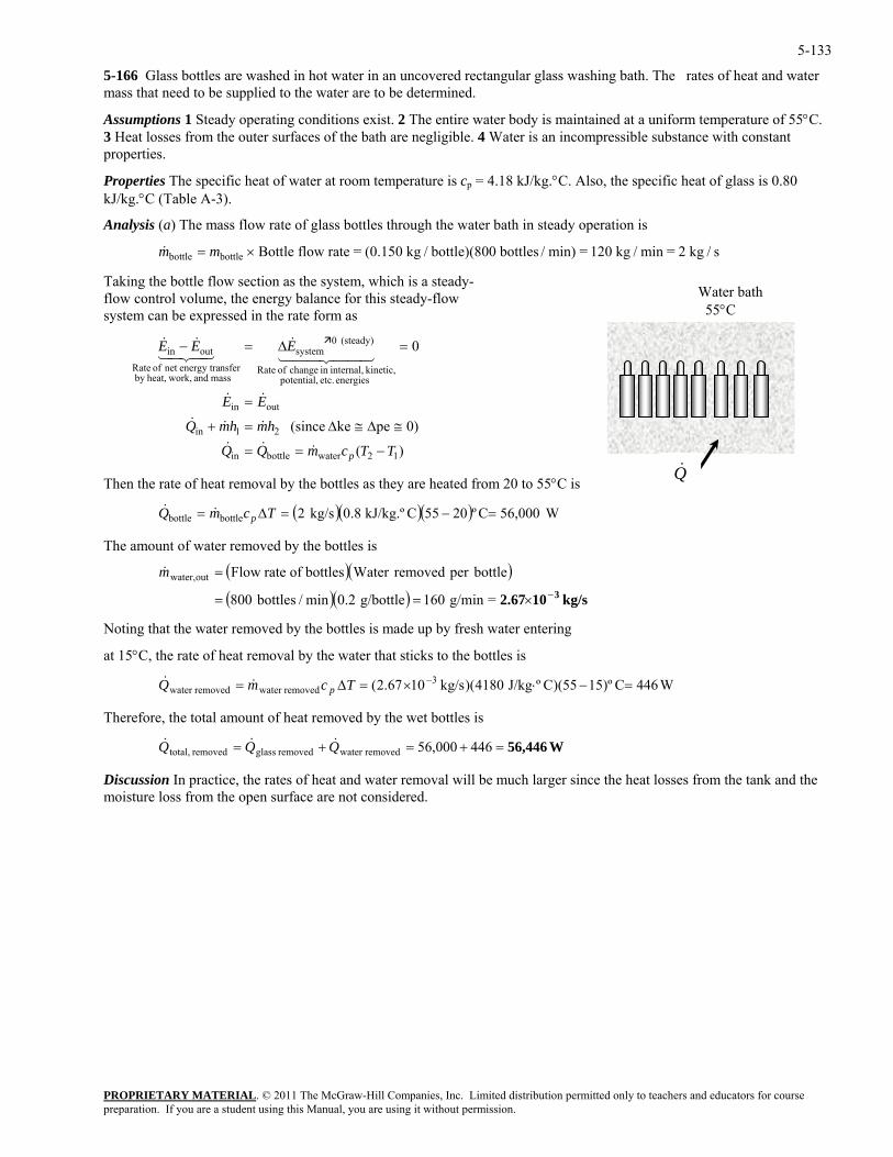
5-133
5-166 Glass bottles are washed in hot water in an uncovered rectangular glass washing bath. The rates of heat and water mass that need to be supplied to the water are to be determined.
Assumptions 1 Steady operating conditions exist. 2 The entire water body is maintained at a uniform temperature of 55°C. 3 Heat losses from the outer surfaces of the bath are negligible. 4 Water is an incompressible substance with constant properties.
Properties The specific heat of water at room temperature is cp = 4.18 kJ/kg.°C. Also, the specific heat of glass is 0.80 kJ/kg.°C (Table A-3).
Analysis (a) The mass flow rate of glass bottles through the water bath in steady operation is
&m mbottle bottle Bottle flow rate = (0.150 kg / bottle)(800 bottles / min) = 120 kg / min = 2 kg / s= ×
Taking the bottle flow section as the system, which is a steady-flow control volume, the energy balance for this steady-flow system can be expressed in the rate form as
Water bath 55°C
PROPRIETARY MATERIAL. © 2011 The McGraw-Hill Companies, Inc. Limited distribution permitted only to teachers and educators for course
e
0
12waterbottlein
outin
(steady) 0systemoutin
TTcmQQ
EE
EEE
p −==
≅
=
=∆=−
&&&
&&
&43421&&
Q&
energies etc. potential, kinetic, internal,in change of Rate
mass and work,heat,by nsferenergy tranet of Rate
44 344 21
)(
0)pke (since 21in hmhmQ ∆≅∆=+ &&&
Then the rate of heat removal by the bottles as they are heated from 20 to 55°C is
( )( )( ) ,0056Cº2055CkJ/kg.º 8.0kg/s 2bottlebottle =−=∆= TcmQ p&& W0
he amount of water removed by the bottles is
=g/min 160 g/bottle 0.2min/bottles 800
tle
t 15°C, the rate of heat removal by the water that sticks to the bottles is
Therefore, the total amount of heat removed by the wet bottles is
Discussion In practice, the rates of heat and water removal will be much larger since the heat losses from the tank and the moisture loss from the open surface are not considered.
T
( )(= botper removedWater bottlesof rate Flowoutwater,m& )( )( ) kg/s102.67 3−×==
Noting that the water removed by the bottles is made up by fresh water entering
a
W446C)º1555)(CºJ/kg 4180)(kg/s1067.2( 3removedwater removedwater =−⋅×=∆= −TcmQ p&&
W56,446=+=+= 446000,56removedwater removed glassremoved total, QQQ &&&
preparation. If you are a student using this Manual, you are using it without permission.
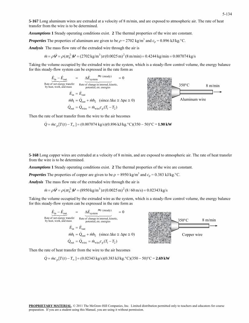
5-134
5-167 Long aluminum wires are extruded at a velocity of 8 m/min, and are exposed to atmospheric air. The rate of heat transfer from the wire is to be determined.
Assumptions 1 Steady operating conditions exist. 2 The thermal properties of the wire are constant.
Properties The properties of aluminum are given to be ρ = 2702 kg/m3 and cp = 0.896 kJ/kg.°C.
Analysis The mass flow rate of the extruded wire through the air is
kg/s 007074.0kg/min 4244.0m/min) 8(m) 0025.0()kg/m 2702()( 2320 ===== ππρρ VV rm &&
Taking the volume occupied by the extruded wire as the system, which is a steady-flow control volume, the energy balance for this steady-flow system can be expressed in the rate form as
PROPRIETARY MATERIAL. © 2011 The McGraw-Hill Companies, Inc. Limited distribution permitted only to teachers and educators for course
(steady) 0systemoutin
TTcmQQ
hmQhm
EE
EEE
p −==
≅∆≅∆+=
=
=∆=−
&&&
&&&
&&
&&&
hen the rate of heat transfer from the wire to the air becomes
-168 Long copper wires are extruded at a velocity of 8 m/min, and are exposed to atmospheric air. The rate of heat transfer om the wire is to be determined.
Properties The properties of copper are given to be ρ = 8950 kg/m3 and cp = 0.383 kJ/kg.°C.
Analysis The mass flow rate of the extruded wire through the air is
/s)60/8(m) 0025.0()kg/m 8950()( 2320 ==== ππρρ VV rm &&
Taking the volume occupied by the extruded wire as the system, which is a steady-flow contr e energy balance for this steady-flow system can be expressed in the rate form as
mass and work,b
TTcmQQ
hmQhm
EE
p −==
≅∆≅∆+=
=
=∆=−
&&&
&&&
&&
&&&
Then the rate of heat transfer from the wire to the air becomes
)(
0)peke (since
0
21wirewireout
2out1
outin
energies etc. potential, kinetic, internal,in change of Rate
mass and work,heat,by nsferenergy tranet of Rate
44 344 2143421350°C Aluminum wire
8 m/min
T
kW 1.90 =C)50350)(CkJ/kg. 896.0)(kg/s 007074.0(])([ °−°=−= ∞TtTcmQ p&&
5fr
Assumptions 1 Steady operating conditions exist. 2 The thermal properties of the wire are constant.
m kg/s 02343.0
ol volume, th
)(
0)peke (since
0
21wirewireout
2out1
outin
energies etc. potential, kinetic, internal,in change of Rate
(steady) 0system
nsferenergy tranet of Rateoutin EEE
44 344 2143421
heat,y
kW 2.69 =C)50350)(CkJ/kg. 383.0)(kg/s 02343.0(])([ °−°=−= ∞TtTcmQ p&&
350°C
Copper wire
8 m/min
preparation. If you are a student using this Manual, you are using it without permission.
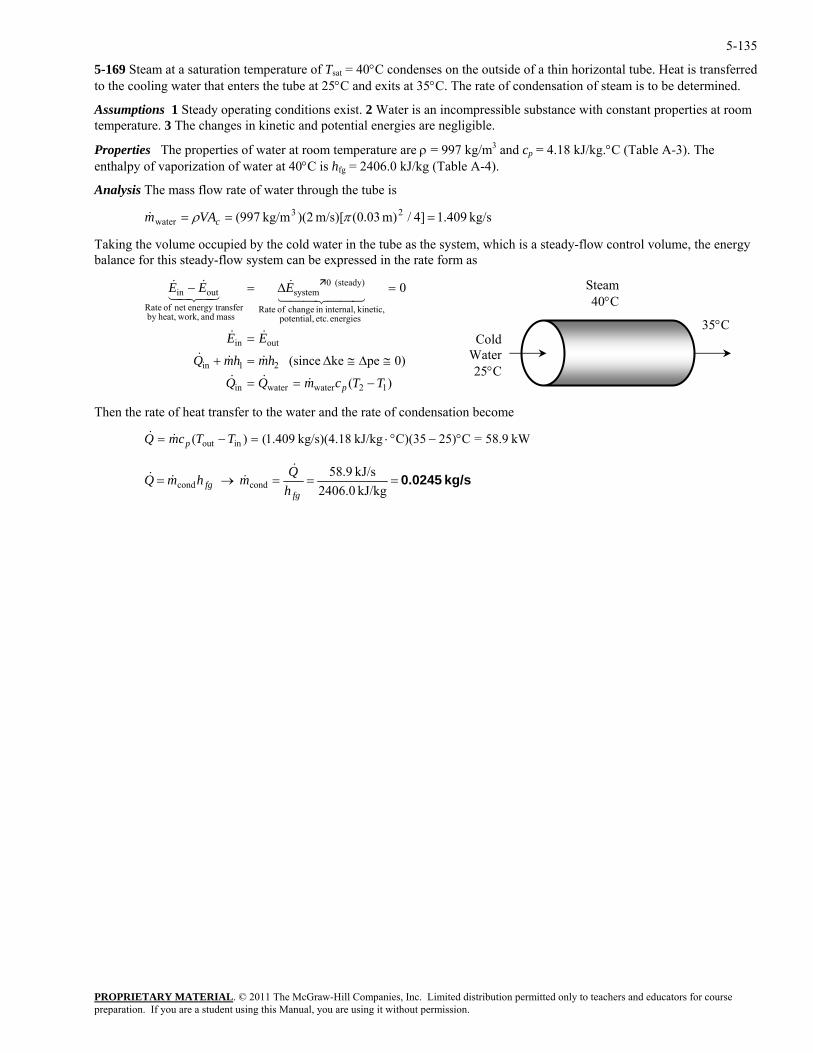
5-135
5-169 Steam at a saturation temperature of Tsat = 40°C condenses on the outside of a thin horizontal tube. Heat is transferred to the cooling water that enters the tube at 25°C and exits at 35°C. The rate of condensation of steam is to be determined.
Assumptions 1 Steady operating conditions exist. 2 Water is an incompressible substance with constant properties at room temperature. 3 The changes in kinetic and potential energies are negligible.
Properties The properties of water at room temperature are ρ = 997 kg/m3 and cp = 4.18 kJ/kg.°C (Table A-3). The enthalpy of vaporization of water at 40°C is hfg = 2406.0 kJ/kg (Table A-4).
Analysis The mass flow rate of water through the tube is
kg/s 409.1]4/m) 03.0(m/s)[ )(2kg/m 997( 23water === πρ cVAm&
Taking the volume occupied by the cold water in the tube as the system, which is a steady-flow control volume, the energy balance for this steady-flow system can be expressed in the rate form as
PROPRIETARY MATERIAL. © 2011 The McGraw-Hill Companies, Inc. Limited distribution permitted only to teachers and educators for course
(steady) 0systemoutin
TTcmQQ
hmhmQ
EE
EEE
p −==
≅∆≅∆=+
=
=∆=−
&&&
&&&
&&
&&&
Then the rate of heat transfer to the water and the rate of condensation become
Steam 40°C
)(
0)peke (since
0
12waterwaterin
21in
outin
energies etc. potential, kinetic, internal,in change of Rate
mass and work,heat,by nsferenergy tranet of Rate
44 344 2143421
35°CCold
Water25°C
kW 58.9=C25)C)(35kJ/kg kg/s)(4.18 409.1()( inout °−°⋅=−= TTcmQ p&&
kg/s 0.0245===→=kJ/kg 2406.0kJ/s 9.58 condcond
fgfg h
QmhmQ&
&&&
preparation. If you are a student using this Manual, you are using it without permission.
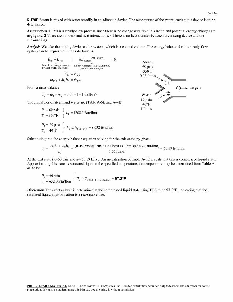
5-136
5-170E Steam is mixed with water steadily in an adiabatic device. The temperature of the water leaving this device is to be determined.
Assumptions 1 This is a steady-flow process since there is no change with time. 2 Kinetic and potential energy changes are negligible. 3 There are no work and heat interactions. 4 There is no heat transfer between the mixing device and the surroundings.
Analysis We take the mixing device as the system, which is a control volume. The energy balance for this steady-flow system can be expressed in the rate form as
332211
outin
energies etc. potential, kinetic, internal,in change of Rate
(steady) 0system
mass and work,heat,by nsferenergy tranet of Rate
outin 0
hmhmhmEE
EEE
&&&
&&
444 344 21&
43421&&
=+=
=∆=−
PROPRIETARY MATERIAL. © 2011 The McGraw-Hill Companies, Inc. Limited distribution permitted only to teachers and educators for course
=+=+= mmm &&
⎫=P
ubstituting into the energy balance equation solving for the exit enthalpy gives
Steam 60 psia 350°F
0.05 lbm/s
3 2
1
Water 60 psia 40°F
1 lbm/s
From a mass balance 60 psia 3& lbm/s 1.05105.021
The enthalpies of steam and water are (Table A-6E and A-4E)
Btu/lbm 3.1208 F350 psia 60
11
1 =⎭⎬⎫
°==
hTP
Btu/lbm 032.8 F40 F40@2
2
2 =≅⎭⎬°= °fhh
T
psia 60
S
Btu/lbm 19.65lbm/s 05.13
22113 ===
mh
&
At the exi
Btu/lbm) 32lbm/s)(8.0 1(Btu/lbm) 8.3lbm/s)(120 05.0( ++ hmhm &&
t state P3=60 psia and h3=65.19 kJ/kg. An investigation of Table A-5E reveals that this is compressed liquid state. pproxim d at the specified temperature, the temperature may be determined from Table A-E to be
⎭=3 Btu/lbm 19.65h
Discussion The exact answer is determined at the compressed liquid state using EES to be 97.0°F, indicating that the saturated liquid approximation is a reasonable one.
A ating this state as saturated liqui4
≅⎬⎫=
= Btu/lbm 65.19@33 psia 60
hfTTP
F97.2°=
preparation. If you are a student using this Manual, you are using it without permission.
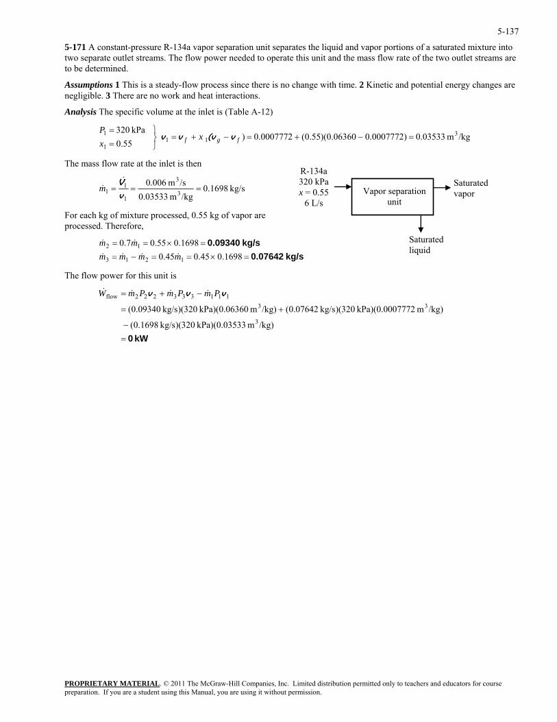
5-137
5-171 A constant-pressure R-134a vapor separation unit separates the liquid and vapor portions of a saturated mixture into two separate outlet streams. The flow power needed to operate this unit and the mass flow rate of the two outlet streams are to be determined.
Assumptions 1 This is a steady-flow process since there is no change with time. 2 Kinetic and potential energy changes are negligible. 3 There are no work and heat interactions.
Analysis The specific volume at the inlet is (Table A-12)
/kgm 03533.0)0007772.006360.0)(55.0(0007772.0)55.0
kPa 320 311
1
1 =−+=−+=⎭⎬⎫
==
fgf xxP
v(v v v
The mass flow rate at the inlet is then
PROPRIETARY MATERIAL. © 2011 The McGraw-Hill Companies, Inc. Limited distribution permitted only to teachers and educators for course
kg/s 1698.0/kgm 0.03533 3
11 ===
v&m /sm 006.0 3
1V&
For each kg of mixture processed, 0.55 kg of vapor are rocessed. Therefore,
=×==1698.045.0
1698.055.07.0 12 mm &&
he flow p wer for this unit is
R-134a 320 kPax = 0.55
6 L/s Vapor separation
unit
Saturated liquid
Saturated vapor
p
=−= 45.0 1213 mmmm &&&& kg/s 0.07642
kg/s 0.09340=×=
T o
kW 0=−
+=
−+=
/kg)m 33kPa)(0.035 320)(kg/s 0.1698(
/kg)m 7772kPa)(0.000 320)(kg/s 0.07642(/kg)m 60kPa)(0.063 320)(kg/s 0.09340(3
33111333222flow vvv PmPmPmW &&&&
preparation. If you are a student using this Manual, you are using it without permission.
5-138
5-172E A small positioning control rocket in a satellite is driven by a container filled with R-134a at saturated liquid state. The number of bursts this rocket experience before the quality in the container is 90% or more is to be determined.
Analysis The initial and final specific volumes are
(Table A-11E) /lbmft 0.011710
F10 31
1
1 v =⎭⎬⎫
=°−=
xT
PROPRIETARY MATERIAL. © 2011 The McGraw-Hill Companies, Inc. Limited distribution permitted only to teachers and educators for course
F10 3=−+⎫°−=T
he initial and final masses in the container are
90.0 22
2=+=
⎭⎬= fgf x
xvv v /lbmft 4394.2)01171.07091.2)(90.0(01171.02
T
lbm 8.170/kgm 0.01171
ft 23
3
1 1 ===
vVm
lbm 8199.0/lbmft 2.4394
ft 23
3
22 ===
vVm
Then,
m lbm 0.1708199.08.17021 =−=−=∆ mm
urst is
ber of bursts that can be executed is then
The amount of mass released during each control b
lbm 0.25s) lbm/s)(5 05.0( ==∆=∆ tmmb &
The num
bursts 680==∆∆
=lbm/burst 0.25
lbm 170.0
bb m
mN
preparation. If you are a student using this Manual, you are using it without permission.
5-139
5-173E The relationships between the mass flow rate and the time for the inflation and deflation of an air bag are given. The volume of this bag as a function of time are to be plotted.
Assumptions Uniform flow exists at the inlet and outlet.
Properties The specific volume of air during inflation and deflation are given to be 15 and 13 ft3/lbm, respectively.
Analysis The volume of the airbag at any time is given by
PROPRIETARY MATERIAL. © 2011 The McGraw-Hill Companies, Inc. Limited distribution permitted only to teachers and educators for course
outin )()() dmdtmt vvV &&
Applying at different time periods as given in problem statement give
( ∫∫ −= timeflowout timeflowin
ms 100 ms 1000
s 1ms 10
lbm/s 20/lbm)ft 15()(0
3 ≤≤⎟⎠⎞
⎜⎝⎛= ∫ ttdtt
t
V
ms 100 /msft 015.0)(0
232 ≤≤= ∫ tttt
V
ms 1210 ms 1000
s 1lbm/s) /lbm)(20ft 15()ms 10()(ms 10
3 ≤<⎟⎠⎞
⎜⎝⎛+= ∫ ttdtt
t
VV
ms 1210 ms) 10(/msft 03.0)ms 10()( 23 ≤<−+= ttt VV
ms 2512 ms) 12(ms 1000
s 1ms 12)-(30
lbm/s 16/lbm)ft 13(
ms) 12(/msft 03.0)ms 12()(
ms 12
3
23
≤<−⎟⎠⎞
⎜⎝⎛−
−+=
∫ tdtt
ttt
VV
ms 2512 ms) 12(/msft 011556.0
ms) 12(/msft 03.0)ms 12()(
ms 12
23
23
≤<−−
−+=
∫ tdtt
ttt
VV
ms 2512 ms) 12(13867.0)ms 144(2
011556.0
ms) 12(/msft 03.0)ms 12()(
22
23
≤<−+−−
−+=
ttt
tt VV
ms 3025 ms) 25(13867.0)ms 625(2
011556.0)ms 25()( 22 ≤<−+−−= tttt VV
ms 5030 ms 1000
s 1lbm/s) /lbm)(16ft 13()ms 30()(ms 12
3 ≤<⎟⎠⎞
⎜⎝⎛−= ∫ tdtt
t
VV
ms 5030 )ms 30(/ms)ft 208.0()ms 30()( 3 ≤<−−= ttt VV
preparation. If you are a student using this Manual, you are using it without permission.
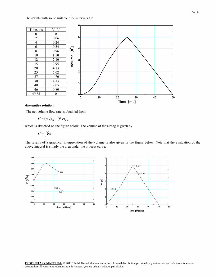
5-140
The results with some suitable time intervals are
PROPRIETARY MATERIAL. © 2011 The McGraw-Hill Companies, Inc. Limited distribution permitted only to teachers and educators for course
Time, ms V, ft3
0 0 2 0.06 4 0.24 6 0.54 8 0.96
10 1.50 12 2.10 15 2.95 20 4.13 25 5.02 27 4.70 30 4.13 40 2.05 46 0.80
49.85 0
Alternative solution
The net volume flow rate is obtained from
outin )()( vvV mm &&& −=
which is sketched on the figure below. The volume of the airbag is given by
∫= dtVV &
The results of a graphical interpretation of the volume is also given in the figure below. Note that the evaluation of the bove integral is simply the area under the process curve.
a
0 10 20 30 40 50 60-400
-300
-200
-100
0
100
200
300
400
time [mlllisec]
V [f
t3 /s]
-208
150
-150
0 10 20 30 40 500
1
2
3
4
5
6
Time [ms]
Volu
me
[ft3 ]
0 10 20 30 40 50 600
1
2
3
4
5
6
V [f
t3 ]
2.10
5.03
4.14
time [millisec]
preparation. If you are a student using this Manual, you are using it without permission.
5-141
5-174E A winterizing project is to reduce the infiltration rate of a house from 2.2 ACH to 1.1 ACH. The resulting cost savings are to be determined.
Assumptions 1 The house is maintained at 72°F at all times. 2 The latent heat load during the heating season is negligible. 3 The infiltrating air is heated to 72°F before it exfiltrates. 4 Air is an ideal gas with constant specific heats at room temperature. 5 The changes in kinetic and potential energies are negligible. 6 Steady flow conditions exist.
Properties The gas constant of air is 0.3704 psia.ft3/lbm⋅R (Table A-1E). The specific heat of air at room temperature is 0.24 Btu/lbm⋅°F (Table A-2E).
PROPRIETARY MATERIAL. © 2011 The McGraw-Hill Companies, Inc. Limited distribution permitted only to teachers and educators for course
Analysis The density of air at the outdoor conditions is
33
lbm/ft 0734.0R) 6.5/lbm.R)(49psia 3704.0(o
o RT .ftpsia 5.13
=== oP
volume of the house is
The energy balance for this imaginary steady-flow system can be expressed in the rate form as
21in
outin
energies etc. potential, kinetic, internal,in change of Rate
mass and work,heat,by nsfer
TTcTTcmQ
hmhmQ
EE
−=−=
≅∆≅∆=+
=
V&&&
&&&
&&
44 344 21
ρ
The
32building ft 500,40ft) )(9ft 4500(ht)area)(HeigFloor ( ===V
We can view infiltration as a steady stream of air that is heated as it flows in an imaginary duct passing through the house.
Cold air 36.5°F
Warm air
72°F
Warm air 72°F
0(steady) 0system
energy tranet of Rate
EEE outin =∆=−
)()(
0)peke (since
1212in pp
The reduction in the infiltration rate is 2.2 – 1.1 = 1.1 ACH. The reduction in the sensible infiltration heat load
&
ρ
corresponding to it is
ce efficiency is 0.92 and the unit cost of natural gas is $1.24/therm, the energy and money saved during the 6-month period are
Therefore, reducing the infiltration rate by one-half will reduce the heating costs of this homeowner by $1622 per year.
43421&&
therm/h0.2786=Btu/h 27,860=F36.5))(72ft 40,500F)(1.1/h)(Btu/lbm. )(0.24lbm/ft 0734.0(
))()((33
buildingsavedsaved on,infiltrati
°−°=
−= oipo TTACHcQ Vρ&
since 1 therm = 100,000 Btu. The number of hours during a six month period is 6×30×24 = 4320 h. Noting that the furna
ar therms/ye1308=92h/year)/0. 4320 therm/h)(2786.0(
ciencyyear)/Effiper hours of No.)((savingsEnergy saved on,infiltrati
=
= Q&
$1622/year=therm)ar)($1.24/ therms/ye1308(
energy) ofcost Unit )(savingsEnergy (savingsCost ==
preparation. If you are a student using this Manual, you are using it without permission.
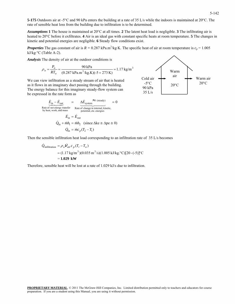
5-142
5-175 Outdoors air at -5°C and 90 kPa enters the building at a rate of 35 L/s while the indoors is maintained at 20°C. The rate of sensible heat loss from the building due to infiltration is to be determined.
Assumptions 1 The house is maintained at 20°C at all times. 2 The latent heat load is negligible. 3 The infiltrating air is heated to 20°C before it exfiltrates. 4 Air is an ideal gas with constant specific heats at room temperature. 5 The changes in kinetic and potential energies are negligible. 6 Steady flow conditions exist.
Properties The gas constant of air is R = 0.287 kPa.m3/kg⋅K. The specific heat of air at room temperature is cp = 1.005 kJ/kg⋅°C (Table A-2).
PROPRIETARY MATERIAL. © 2011 The McGraw-Hill Companies, Inc. Limited distribution permitted only to teachers and educators for course
Analysis The density of air at the outdoor conditions is
33 K) 273/kg.K)(-5kPa.m 287.0( +o
o RT
We can view infiltration as a steady stream of air that is heated as it flows in an imaginary duct passing through the building. The energy balance for this imaginary steady-flow system
kg/m 17.1kPa 90=== oP
can be expressed in the rate form as
21in
outin
energies etc. potential, kinetic, internal,in change of Rate
(steady) 0system
mass and work,heat,by nsferenergy tranet of Rate
outin
hmhmQ
EE
EEE
≅∆≅∆=+
=
=∆=−
&&&
&&
44 344 21&
43421&&
Then the sensible infiltration heat load corresponding to an infiltration rate of 35 L/s becomes
33 °°=
Therefore, sensible heat will be lost at a rate of 1.029 kJ/s due to infiltration.
Cold air -5°C
90 kPa 35 L/s
Warm air
20°C
ρ
Warm air 20°C
0)peke (since
0
)( 12in TTcmQ p −= &&
)(oninfiltrati −= oipairo TTcQ V&& ρ
kW 1.029=C(-5)]-C)[20kJ/kg. /s)(1.005m )(0.035kg/m 17.1(
preparation. If you are a student using this Manual, you are using it without permission.
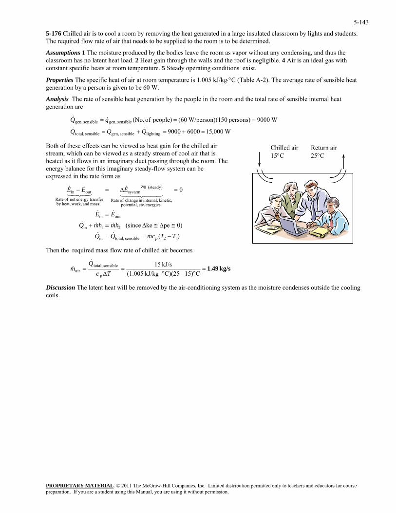
5-143
5-176 Chilled air is to cool a room by removing the heat generated in a large insulated classroom by lights and students. The required flow rate of air that needs to be supplied to the room is to be determined.
Assumptions 1 The moisture produced by the bodies leave the room as vapor without any condensing, and thus the classroom has no latent heat load. 2 Heat gain through the walls and the roof is negligible. 4 Air is an ideal gas with constant specific heats at room temperature. 5 Steady operating conditions exist.
Properties The specific heat of air at room temperature is 1.005 kJ/kg⋅°C (Table A-2). The average rate of sensible heat generation by a person is given to be 60 W.
Analysis The rate of sensible heat generation by the people in the room and the total rate of sensible internal heat generation are
W000,1560009000
W9000=persons) (150 W/person)60(people) of (No.
lightingsensible gen,sensible total,
sensible gen,sensible gen,
=+=+=
==
QQQ
qQ&&&
&&
Both of these effects can be viewed as heat gain for the chilled air stream, which can be viewed as a steady stream of cool air that is heated as it flows in an imaginary duct passing through the room. The energy balance for this imaginary steady-flow system can be expressed in the rate form as
PROPRIETARY MATERIAL. © 2011 The McGraw-Hill Companies, Inc. Limited distribution permitted only to teachers and educators for course
21in
outin
energies etc. potential,
(steady) 0systemoutin
hmhmQ
EE
EEE
≅∆≅∆=+
=
=∆=−
&&&
&&
&&&
ass flow rate of chilled air becomes
Chilled air 15°C
Return air 25°C
0)peke (since
0kinetic, internal,in change of Rate
mass and work,heat,by nsferenergy tranet of Rate
44 344 2143421
)( 12sensible total,in TTcmQQ p −== &&&
Then the required m
kg/s 1.49=°−°⋅
=∆
=C15)C)(25kJ/kg (1.005
kJ/s 15sensible total,air Tc
Qm
p
&&
Discussion The latent heat will be removed by the air-conditioning system as the moisture condenses outside the cooling coils.
preparation. If you are a student using this Manual, you are using it without permission.
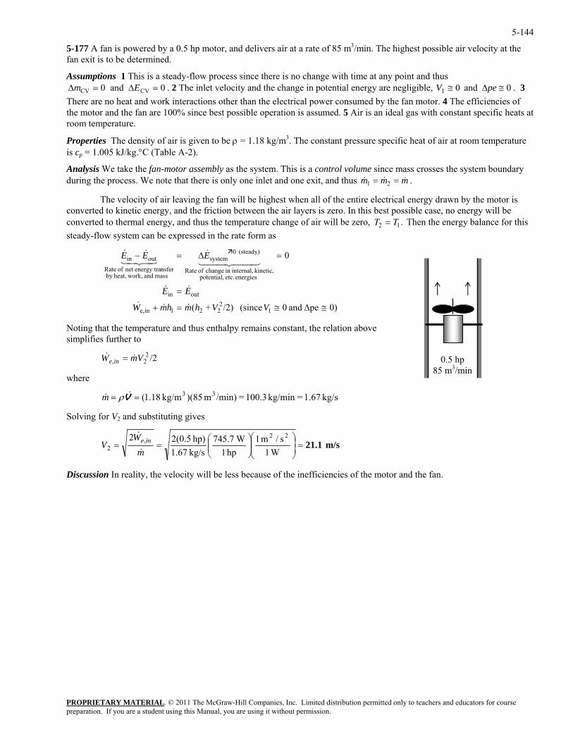
5-144
5-177 A fan is powered by a 0.5 hp motor, and delivers air at a rate of 85 m3/min. The highest possible air velocity at the fan exit is to be determined.
PROPRIETARY MATERIAL. © 2011 The McGraw-Hill Companies, Inc. Limited distribution permitted only to teachers and educators for course
nge in potential eneAssumptions 1 This is a steady-flow process since there is no change with time at any point and thus ∆ ∆m ECV CV and = =0 0 . 2 The inlet velocity and the cha rgy are negligible, 0 and 01 ≅∆≅ peV . 3 There are no heat and work interactions other than the electrical power consumed by the fan motor. 4 The efficiencies of the motor and the fan are 100% since best possible operation is assumed. 5 Air is an ideal gas with constant specific heats at
n to be ρ = 1.18 kg/m3. The constant pressure specific heat of air at room temperature
ince mass crosses the system boundary
room temperature.
Properties The density of air is giveis cp = 1.005 kJ/kg.°C (Table A-2).
Analysis We take the fan-motor assembly as the system. This is a control volume sduring the process. We note that there is only one inlet and one exit, and thus & & &m m m1 2= = .
The velocity of air leaving the fan will be highest when all of the entire electrical energy drawn by the motor isconverted to kinetic energy, and the friction between the air layers is zero. In this best possible case, no energy will be converted to thermal energy, and thus the temperature ch
ange of air will be zero, T T2 1= . Then the energy balance for this w can be expressed in the rate form as
12
221ine,
outin
energies etc. potential, kinetic, internal,in change of Rate
mass and work,heat,by nsfergy tra
≅∆≅=+
=
VVhmhmW
E
&&&
&&
steady-flo system
0)pe and 0 (since /2)+(
0(steady) 0system
enernet of Rateoutin =∆=− EEE
44 344 21
E
&
oting tha he temperature and thus enthalpy remains constant, the relation above
where
olving for V2 and substituting gives
43421&&
N t tsimplifies further to
/222, VmW ine && =
kg/s 1.67=kg/min 100.3=/min)m )(85kg/m 18.1( 33== V&& ρm
S
m/s 21.1=⎟⎟⎠
⎞⎜⎜⎝
⎛⎟⎟⎠
⎞⎜⎜⎝
⎛==
W1s/m 1
hp 1 W7.745
kg/s 67.1hp) 5.0(22 22
,2 m
WV ine
&
&
Discussion In reality, the velocity will be less because of the inefficiencies of the motor and the fan.
0.5 hp 85 m3/min
preparation. If you are a student using this Manual, you are using it without permission.
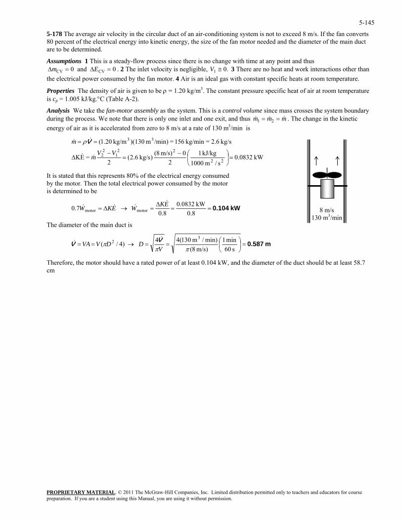
5-145
5-178 The average air velocity in the circular duct of an air-conditioning system is not to exceed 8 m/s. If the fan converts 80 percent of the electrical energy into kinetic energy, the size of the fan motor needed and the diameter of the main duct are to be determined.
PROPRIETARY MATERIAL. © 2011 The McGraw-Hill Companies, Inc. Limited distribution permitted only to teachers and educators for course
2 Assumptions 1 This is a steady-flow process since there is no change with time at any point and thus ∆ ∆m ECV CV and = =0 0 The inlet velocity is negligible, .01. ≅V 3 There are no heat and work interactions other thanthe electrical power consumed by the fan motor. 4 Air is an ideal gas with constant
specific heats at room temperature.
m
Properties The density of air is given to be ρ = 1.20 kg/m3. The constant pressure specific heat of air at room temperature is cp = 1.005 kJ/kg.°C (Table A-2).
Analysis We take the fan-motor assembly as the system. This is a control volume since mass crosses the system boundary during the process. We note that there is only one inlet and one exit, and thus & &m m1 2& = = . The change in the kinetic energy of air as it is accelerated from zero to 8 m/s at a rate of 130 m3/min is
8 m/s 130 m3/min
kW 0832.0s/m 1000
kJ/kg 12
0m/s) 8()kg/s 6.2(2
=EK
kg/s 2.6=kg/min 156=/min)m )(130kg/m 20.1(
22
221
22
33
=⎟⎠
⎞⎜⎝
⎛−=
−∆
==
VVm
m
&&
&& Vρ
It is stated that this represents 80% of the electrical energy consumed by the motor. Then the total electrical power consumed by the motor is determined to be
kW 0.104==∆
=→∆= 7.0 motormotor WEKW &&&0.8
kW 0832.08.0EK &
The diameter of the main duct is
m 0.587=⎟⎠
⎜⎝
==→==s 60m/s) 8(
)4/(ππ
πV
DDVVAV
Therefore, the m
⎞⎛ min 1min)/m 130(44 32 V&&
otor should have a rated power of at least 0.104 kW, and the diameter of the duct should be at least 58.7 m
c
preparation. If you are a student using this Manual, you are using it without permission.
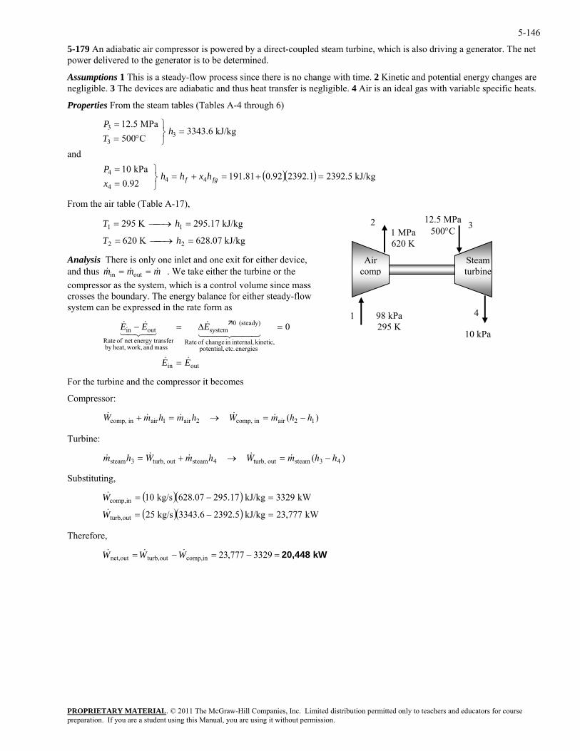
5-146
5-179 An adiabatic air compressor is powered by a direct-coupled steam turbine, which is also driving a generator. The net power delivered to the generator is to be determined.
Assumptions 1 This is a steady-flow process since there is no change with time. 2 Kinetic and potential energy changes are negligible. 3 The devices are adiabatic and thus heat transfer is negligible. 4 Air is an ideal gas with variable specific heats.
Properties From the steam tables (Tables A-4 through 6)
PROPRIETARY MATERIAL. © 2011 The McGraw-Hill Companies, Inc. Limited distribution permitted only to teachers and educators for course
and
MPa 12.5
444 =+=+=
⎭⎬⎫
==
⎫=
fgf hxhhxP
P
Analysis There is only one inlet and one exit for either device, nd thus . We take either the turbine or th
compressor as the system, which is a control volume since mass crosses the boundary. The energy balance for either steady-flow
nsferenergy tranet of Rate
out 0
EE
EE
&&
44 344 21&
43&
=
=∆=−
For the turbine and the compressor it becomes
omp, in air air comp, in air ) + = → = −1 2 2 1
3 4
Substituting,
Therefore,
( )( ) kJ/kg 2392.52392.10.92191.8192.0kPa 10
kJ/kg 3343.6C500 3
3=
⎭⎬°=
hT
3
4
From the air table (Table A-17),
K 620
kJ/kg 295.17K 295
22
11
=⎯→⎯=
=⎯→⎯=
hT
hT
98 kPa 295 K
1 MPa 620 K
10 kPa
12.5 MPa 500°C
Aircom
p
Steam
1
2 3
4
turbine
kJ/kg 628.07
a e outin mmm &&& ==
system can be expressed in the rate form as
outin
energies etc. potential, kinetic, internal,in change of Rate
(steady) 0system
mass and work,heat,b
inE421&
y
Compressor:
&c & & & & (W m h m h W m h h
Turbine:
& & & & & (m h W m h W m h hsteam turb, out steam turb, out steam ) 3 4= + → = −
( )( )( )( ) kW 23,777kJ/kg 2392.53343.6kg/s 25
kW 3329kJ/kg 295.17628.07kg/s 10
outturb,
incomp,
=−=
=−=
W
W&
&
kW 20,448=−=−= 3329777,23incomp,outturb,outnet, WWW &&&
preparation. If you are a student using this Manual, you are using it without permission.
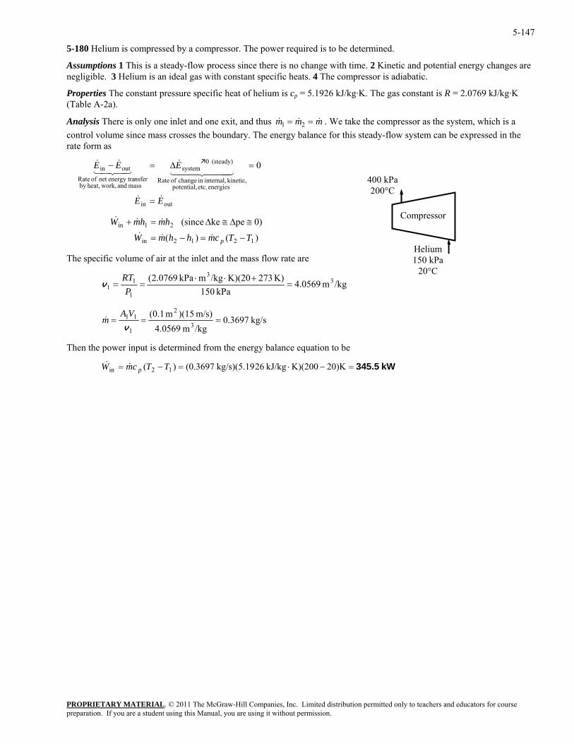
5-147
5-180 Helium is compressed by a compressor. The power required is to be determined.
Assumptions 1 This is a steady-flow process since there is no change with time. 2 Kinetic and potential energy changes are negligible. 3 Helium is an ideal gas with constant specific heats. 4 The compressor is adiabatic.
Properties The constant pressure specific heat of helium is cp = 5.1926 kJ/kg·K. The gas constant is R = 2.0769 kJ/kg·K (Table A-2a).
PROPRIETARY MATERIAL. © 2011 The McGraw-Hill Companies, Inc. Limited distribution permitted only to teachers and educators for course
&Analysis There is only one inlet and one exit, and thus mm &&m == 21 . We take the compressor as the system, which is a control volume since mass crosses the boundary. The energy balance for this steady-flow system can be expressed in the rate form as
energies etc. potential,
kinetic, internal,in change of Rate
(steady) 0system
mass and work,heat,by nsferenergy tranet of Rate
outin 0
E
EEE
&
444 344 21&
43421&& =∆=−
1212in TTcmhhmW p −=−= &&&
The specific volume of air at the inlet and the mass flow rate are
Compressor
400 kPa200°C
Helium 150 kPa
20°C
inE& = out
0)peke (since 21in hmhmW ≅∆≅∆=+ &&&
)()(
/kgm 0569.4kPa 1501
1 ===P
v K) 273K)(20/kgmkPa 0769.2( 3
31 +⋅⋅RT
kg/s 0.3697/kgm 4.0569m/s) )(15m 1.0(
3
2
1
11 ===v
VAm&
Then the power input is determined from the energy balance equation to be
kW 345.5=−⋅=−= 0)K2K)(200kJ/kg 26kg/s)(5.19 (0.3697)( 12in TTcmW p&&
preparation. If you are a student using this Manual, you are using it without permission.
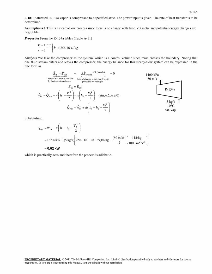
5-148
5-181 Saturated R-134a vapor is compressed to a specified state. The power input is given. The rate of heat transfer is to be determined.
Assumptions 1 This is a steady-flow process since there is no change with time. 2 Kinetic and potential energy changes are negligible.
Properties From the R-134a tables (Table A-11)
PROPRIETARY MATERIAL. © 2011 The McGraw-Hill Companies, Inc. Limited distribution permitted only to teachers and educators for course
⎫°=T
take the compressor as the system, which is a control volume since mass crosses the boundary. Noting that one fluid stream enters and leaves the compressor, the energy balance for this steady-flow system can be expressed in the rate form as
kJ/kg 16.2561 1
1=
⎭⎬=
hx
Analysis We
C011
⎟⎟⎠
⎞⎜⎜⎝
⎛−−+=
≅∆⎟⎟⎠
⎞⎜⎜⎝
⎛+=⎟
⎟⎠
⎞⎜⎜⎝
⎛++−
=
=∆=−
2
0)pe (since 22
0
22
21inout
22
2
21
1outin
outin
energies etc. potential, kinetic, internal,in change of Rate
(steady) 0system
mass and work,heat,by nsferenergy tranet of Rate
outin
VhhmWQ
Vhm
VhmQW
EE
EEE
&&&
&&&&
&&
444 3444 21&
43421&&
R-134a
1400 kPa 50 m/s
5 kg/s 10°C
sat. vap.
S gubstitutin ,
kW 0.02=⎥⎥⎦
⎤
⎢⎢⎣
⎡⎟⎠
⎞⎜⎝
⎛−−+=
⎟⎟⎠
⎞⎛ 2V⎜⎜⎝
−−+=
22
2
221inout
/sm 1000kJ/kg 1
2m/s) (50kg281.39)kJ/256.116kg/s) 5(kW 4.132
2hhmWQ &&&
which is practically zero and therefore the process is adiabatic.
preparation. If you are a student using this Manual, you are using it without permission.
5-149
5-182 A submarine that has an air-ballast tank originally partially filled with air is considered. Air is pumped into the ballast tank until it is entirely filled with air. The final temperature and mass of the air in the ballast tank are to be determined.
Assumptions 1 Air is an ideal gas with constant specific heats. 2 The process is adiabatic. 3 There are no work interactions.
Properties The gas constant of air is R = 0.287 kPa⋅m3/kg⋅K (Table A-1). The specific heat ratio of air at room temperature is k = 1.4 (Table A-2a). The specific volume of water is taken 0.001 m3/kg.
Analysis The conservation of mass principle applied to the air gives
inmdt
dma &=
and as applied to the water becomes
outmdt
dmw &−=
The first law for the ballast tank produces
aawwdtdtwa mhmh
mudmud&& −++=
)()(0
ombining is with the conservation of mass expressions, rearranging and canceling the common dt term produces
tegrating this result from the beginning to the end of the process gives
C th
wwaawa dmhdmhmudmud +=+ )()(
In
[ ] [ ] wwaawa mmhmmhmumumumu )()()()()()( 12121212 −+−=−+−
Substituting the ideal gas equation of state and the specific heat models for the enthalpies and internal energies expands this
to
wwwpwww TcmRTP
RTPPP 212 ⎛ VVV
TcTcmTcRT
TcRT 1,
1
1
2in1,1
12
2−⎟⎟
⎠
⎞⎜⎜⎝
−=−−V
vv
When the common terms are cancelled, this result becomes
K 386.8=+
==10011
22 V
VT
−+ 100)-(700(1.4)(293)
1288
700
)( 12in1
VVkTT
he final mass from the ideal gas relation is
T
kg 9460=⋅⋅
==K) K)(386.8/kgmkPa 287.0(
)m kPa)(700 1500(3
3
2
22 RT
Pm
V
PROPRIETARY MATERIALpreparation. If you are a student using this Manual, you are using it without permission.
. © 2011 The McGraw-Hill Companies, Inc. Limited distribution permitted only to teachers and educators for course
5-150
5-183 A submarine that has an air-ballast tank originally partially filled with air is considered. Air is pumped into the ballast tank in an isothermal manner until it is entirely filled with air. The final mass of the air in the ballast tank and the total heat transfer are to be determined.
Assumptions 1 Air is an ideal gas with constant specific heats. 2 There are no work interactions.
Properties The gas constant of air is R = 0.287 kPa⋅m3/kg⋅K (Table A-1). The specific heats of air at room temperature are cp = 1.005 kJ/kg·K and cv = 0.718 kJ/kg·K (Table A-2a). The specific volume of water is taken 0.001 m3/kg.
Analysis The initial air mass is
kg 1814K) K)(288.15/kgmkPa 287.0(
)m kPa)(100 1500(3
3
1
111 =
⋅⋅==
RTP
mV
and the initial water mass is
PROPRIETARY MATERIAL. © 2011 The McGraw-Hill Companies, Inc. Limited distribution permitted only to teachers and educators for course
kg 000,600/kgm 001.0 3
1===
vwm m 600 31V
nd the final mass of air in the tank is a
kg 12,697=⋅⋅
==K)(28/kgmkPa 287.0( 3
22 RT
mK) 8.15
)m kPa)(700 1500( 322P V
he first la when adapted to this system gives
pwwwwa
iiee
eeii
)()( 121,2in
112in
1122
−−++−=−+−=
−=−+
vv
ubstituting,
T w
Qin
2
TcmmhmumTcmTcmQhmhmumumQ
umumhmhm
Noting that
98.62=≅ ww hu kJ/kg
S
kJ 0=
××−−×+×+××−××=
288005.1)1814697,12(98.62000,600)98.62000,600288718.01814(288718.0697,12inQ
The process is adiabatic.
preparation. If you are a student using this Manual, you are using it without permission.
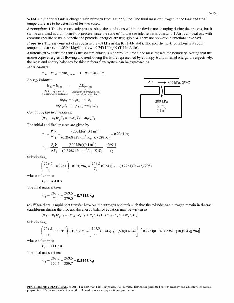
5-1515-184 A cylindrical tank is charged with nitrogen from a supply line. The final mass of nitrogen in the tank and final temperature are to be determined for two cases. Assumptions 1 This is an unsteady process since the conditions within the device are changing during the process, but it can be analyzed as a uniform-flow process since the state of fluid at the inlet remains constant. 2 Air is an ideal gas with constant specific heats. 3 Kinetic and potential energies are negligible. 4 There are no work interactions involved. Properties The gas constant of nitrogen is 0.2968 kPa·m3/kg·K (Table A-1). The specific heats of nitrogen at room temperature are cp = 1.039 kJ/kg·K and cv = 0.743 kJ/kg·K (Table A-2a). Analysis (a) We take the tank as the system, which is a control volume since mass crosses the boundary. Noting that the microscopic energies of flowing and nonflowing fluids are represented by enthalpy h and internal energy u, respectively, the mass and energy balances for this uniform-flow system can be expressed as Mass balance:
12systemoutin mmmmmm i −=→∆=−
200 kPa 25°C
0.1 m3
800 kPa, 25°CAir Energy balance:
es
PROPRIETARY MATERIAL. © 2011 The McGraw-Hill Companies, Inc. Limited distribution permitted only to teachers and educators for course
1122
1122
mTcmTcmii
−=
energi etc. potential, kinetic, internal,in ange
system
mass and work,heat,by
outin
Tcumumhm
EEE
ipi vv
−=
∆=−43421
Combining the two balances:
final masses are given by
Chnsferenergy traNet 43421
112212 )( TcmTcmTcmm ip vv −=−
The initial and
kg 2261.0)K 298)(K/kgmkPa 0.2968(
)m 1.0)(kPa 200(3
3
11 RT
1 =⋅⋅
==P
mV
223
3
2
22
(RTm ==
5.269)K/kgmkPa 0.2968
)m 1.0)(kPa 080(TT
P=
⋅⋅
V
Substituting,
)298)(743.0)(2261.0()743.0(5.269)298)(039.1(2261.05.2692 −=⎟⎟
⎞⎜⎜⎛
− T22 ⎠⎝ TT
n is T
en
whose solutioK 379.0=2
The final mass is th
kg 0.7112===0.3795.269 5.269m
) When there is rapid heat transfer between the nitrogen and tank such that the cylinder and nitrogen remain in thermal equilibrium during the process, the energy balance equation may be written as
22 T
(b
)()()( 111,222,12 TcmTcmTcmTcmTcmm ttnitttnitip +−+=− vv
Substituting,
[ ])298)(43.0)(50()298)(743.0)(2261.0()43.0)(50()743.0(5.269)298)(039.1(2261.05.26922
22+−⎥
⎦
⎤⎢⎣
⎡+=⎟⎟
⎠
⎞⎜⎜⎝
⎛− TT
TT
whose solution is The final mass is then
K 300.7=2T
kg 0.8962===7.3005.269
7.3005.269
2m
preparation. If you are a student using this Manual, you are using it without permission.
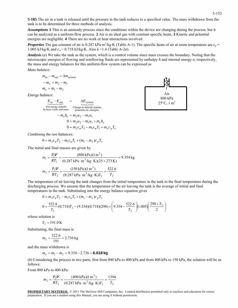
5-1525-185 The air in a tank is released until the pressure in the tank reduces to a specified value. The mass withdrawn from the tank is to be determined for three methods of analysis. Assumptions 1 This is an unsteady process since the conditions within the device are changing during the process, but it can be analyzed as a uniform-flow process. 2 Air is an ideal gas with constant specific heats. 3 Kinetic and potential energies are negligible. 4 There are no work or heat interactions involved. Properties The gas constant of air is 0.287 kPa·m3/kg·K (Table A-1). The specific heats of air at room temperature are cp = 1.005 kJ/kg·K and cv = 0.718 kJ/kg·K. Also k =1.4 (Table A-2a). Analysis (a) We take the tank as the system, which is a control volume since mass crosses the boundary. Noting that the microscopic energies of flowing and nonflowing fluids are represented by enthalpy h and internal energy u, respectively, the mass and energy balances for this uniform-flow system can be expressed as Mass balance:
21
12
systemoutin
mmm
mmm
mmm
e
e
−=−=−
∆=−
Energy balance:
PROPRIETARY MATERIAL. © 2011 The McGraw-Hill Companies, Inc. Limited distribution permitted only to teachers and educators for course
umumhm
EEE
+−=+
−=−
∆=−
1122
energies etc. potential,kinetic, internal,in ange
systemoutin
0 vv
43421
ombining the two balances:
Ch
mass and work,heat,by nsferenergy traNet
43421
epe
ee
ee
TcmTcmTcmhmumum −= 1122
1122
0
C
epTcmmTcmTcm )(0 211122 −+−= vv
The initial and final masses are given by
kg 354.9)m 1)(kPa 080( 3
1 ===P
mV
)K 27325)(K/kgmkPa 0.287( 3
1 +⋅⋅RT1
223
3
2
The temperature of air leaving th
22
6.522)K/kgmkPa 0.287
)m 1)(kPa 015(TTRT
m =⋅⋅
==
e tank changes from the initial temperature in the tank to the final temperature during the ischargin rocess. We assume that the temperature of the air leaving the tank is the average of initial and final
bstituting into the energy balance equation gives
P V
(
d g ptemperatures in the tank. Su
⎟⎟⎞
⎜⎛ +
⎟⎞
⎜⎛
−+−=298
)005.1(6.522354.9)298)(718.0)(354.9()718.0(6.5220 2TT
⎠⎜⎝⎟
⎠⎜⎝
−+−=
2
)(0
22
211122
TT
TcmmTcmTcm epvv
2T
ubstituting, the final mass is
2
uwhose sol tion is 191.0= K
S
kg 736.2191
6.522 2 ==m
nd the mass withdrawn is
in two parts, first from 800 kPa to 400 kPa and from 400 kPa to 150 kPa, the solution will be as
rom 800 kPa to 400 kPa:
a e kg 6.618=−=−= 736.2354.921 mmm
(b) Considering the processfollows: F
22
3
3
2
22
1394)K/kgmkPa 0.287(
)m 1)(kPa 400(TTRT
P=
⋅⋅==
V
Air 800 kPa
25°C, 1 m3
m
preparation. If you are a student using this Manual, you are using it without permission.
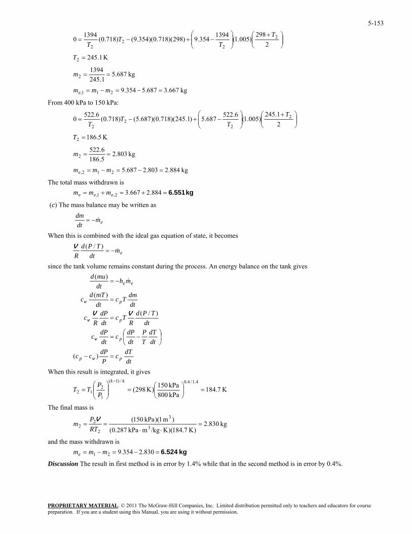
5-153
⎟⎟⎠
⎞⎜⎜⎝
⎛ +⎟⎟⎠
⎞⎜⎜⎝
⎛−+−=
2298
)005.1(1394354.9)298)(718.0)(354
PROPRIETARY MATERIAL. © 2011 The McGraw-Hill Companies, Inc. Limited distribution permitted only to teachers and educators for course
.9()718.0(13940 2
22
2
TT
TT
K 1.2452 =T
kg 687.51.245
13942 ==m
687.5354.9 =−=−= mmm kg 667.32 11,e
From 400 kPa to 150 kPa:
⎟⎟⎠
⎞⎜⎜⎝
⎛ +⎟⎟⎠
⎞⎜⎜⎝
⎛−+−=
21.245
)005.1(6.522687.5)1.245)(718.0)(687.5()718.0(6.5220 2
2 2
2
TT
TT
K 5.1862 =T
kg 803.25.1862 ==m 6.522
The total mass withdrawn is 884.2667.32,1 em
(c) The m alance may be written as
kg 884.2803.2687.5212, =−=−= mmme
= ,ee mm kg 6.551=+=+
ass b
emdtdm
&−=
When this is combined with the ideal gas equation of state, it becomes
emdt
TPdR
&−=)/(V
since the tank volume remains constant during the process. An energy balance on the tank gives
dtdTc
PdPcc
dtdT
TP
dtdPc
dtdPc
dtTPd
RTc
dtdP
Rc
dtdmTc
dtmTdc
mhdtmud
pp
p
p
p
ee
=−
⎟⎠⎞
⎜⎝⎛ −=
=
=
−=
)(
)/(
)(
)(
v
v
v
v
VV
&
When this result is integrated, it gives
K 7.184kPa 800kPa 150)K 298(
4.1/4.0/)1(
1
212 =⎟
⎠⎞
⎜⎝⎛=⎟⎟
⎠
⎞⎜⎜⎝
⎛=
− kk
PP
TT
The final mass is
kg 830.2)K 7.184)(K/kgmkPa 0.287(
)m 1)(kPa 015(3
3
2
22 =
⋅⋅==
RTP
mV
and the mass withdrawn is
Discussion The result in first method is in error by 1.4% while that in the second method is in error by 0.4%.
kg 6.524=−=−= 830.2354.921 mmme
preparation. If you are a student using this Manual, you are using it without permission.
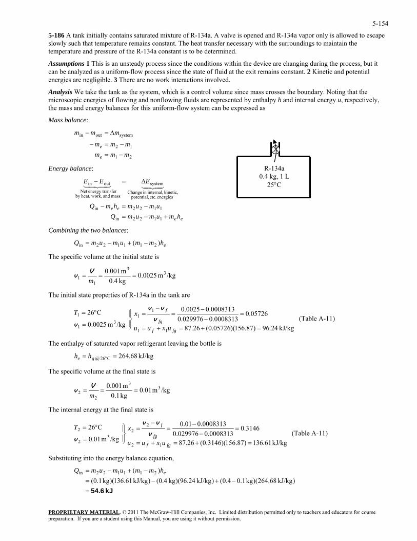
5-154
5-186 A tank initially contains saturated mixture of R-134a. A valve is opened and R-134a vapor only is allowed to escape slowly such that temperature remains constant. The heat transfer necessary with the surroundings to maintain the temperature and pressure of the R-134a constant is to be determined.
Assumptions 1 This is an unsteady process since the conditions within the device are changing during the process, but it can be analyzed as a uniform-flow process since the state of fluid at the exit remains constant. 2 Kinetic and potential energies are negligible. 3 There are no work interactions involved.
Analysis We take the tank as the system, which is a control volume since mass crosses the boundary. Noting that the microscopic energies of flowing and nonflowing fluids are represented by enthalpy h and internal energy u, respectively, the mass and energy balances for this uniform-flow system can be expressed as
Mass balance:
PROPRIETARY MATERIAL. © 2011 The McGraw-Hill Companies, Inc. Limited distribution permitted only to teachers and educators for course
mmmmm
mmm
e
e
−=−=
∆=−
Energy balance:
hmumumQumu
EEE
+−=−
∆=−
1122in
1122
energies etc. potential, kinetic, internal,in Change
system
mass and work,heat,by nsferenergy traNet
outin 4342143421
The specific volume at the initial state is
21
12
systemoutin
R-134a 0.4 kg, 1 L
25°C
m−
ee mhmQ =−in
ee
Combining the two balances:
ehmmumumQ )( 211122in −+−=
/kgm 0.0025kg 4.01
1 ==m
m 001.0 33V=v
The initial state properties of R-134a in the tank are
kJ/kg 24.96)87.156)(05726.0(26.87
05726.00008313.0029976.0
0008313.00025.0
/kgm 0025.01
31
⎪⎭⎬
=v
v
C26
11
1
=+=+=
=−−
==⎪⎫°=
fgf
fg
f
uxuu
xTvv
(Table A-11)
t leaving the bottle is
he specific volume at the final state is
−
1
The enthalpy of saturated vapor refrigeran
kJ/kg 68.264C62@ == °ge hh
T
/kgm 0.01kg 1.0
3
22 ===
mv m 001.0 3V
he intern energy at the final state is
T al
kJ/kg 61.136)87.156)(3146.0(26.87
3146.00008313.0029976.0
0008313.001.0
/kgm 01.0
C26
12
22
32
2
=+=+=
=−
−=
−=
⎪⎭
⎪⎬⎫
=
°=
fgf
fg
f
uxuu
xTv
vv
v (Table A-11)
Substituting into the energy balance equation,
kJ 54.6=
−+−=−+−=
)kJ/kg 68.264)(kg 1.04.0()kJ/kg 24.96)(kg 4.0()kJ/kg 61.136)(kg 1.0()( 211122in ehmmumumQ
preparation. If you are a student using this Manual, you are using it without permission.
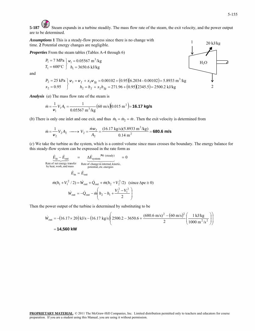
5-155
5-187 Steam expands in a turbine steadily. The mass flow rate of the steam, the exit velocity, and the power output are to be determined.
Assumptions 1 This is a steady-flow process since there is no change with time. 2 Potential energy changes are negligible.
Properties From the steam tables (Tables A-4 through 6)
and
7/kgm 5.89330.00102-6.20340.950.00102kPa 25
/kgm 0.05567MPa 7
3222
31
=+=+=⎬⎫=
=⎫=
fgf xP
P
vvv
v
Analysis (a) The mass flow rate of the steam is
kJ/kg 3650.6C600 11 =⎭⎬°= hT
1
( )( )( )( ) kJ/kg 2500.22345.50.952 1.9695.0 222 =+=+=⎭= fgf hxhhx
( )( ) kg/s 16.17=== 2311
1 /kgm 0.05567v
(b) There is only one inlet and one exit, and thus & & &m m m1 2
m 0.015m/s 6011 AVm&
= = . Then the exit velocity is determined from
m/s 680.6===⎯→⎯= 2
3
2
2222
2 m 0.14)/kgm 5.8933)(kg/s .1716(1
Am
VAVmv
v
&&
(c) We take the turbine as the system, which is a control volume since mass crosses the boundary. The energy balance for this steady-flow system can be expressed in the rate form as
mass and work,heat,b nsferenergy tranet of Rate
EE &&
PROPRIETARY MATERIAL. © 2011 The McGraw-Hill Companies, Inc. Limited distribution permitted only to teachers and educators for course
outin
energies etc. potential, kinetic, internal,in change of Rate
(steady) 0systemoutin 0EEE
44 344 21
y
&
=
43421&& =∆=−
⎟⎟⎠
⎞⎜⎜⎝
⎛ −+−−−=
≅∆++=+
2
0)pe (since /2)+()2/(2
12
212outout
222outout
211
VVhhmQW
VhmQWVhm
&&&
&&&&
Then the power output of the turbine is determined by substituting to be
( ) ( ) ( )
kW 14,560=
⎟⎟
⎠
⎞
⎜⎜
⎝
⎛⎟⎟⎠
⎞⎜⎜⎝
⎛−+−−×−= 22
22
out/sm 1000
kJ/kg 12
m/s 60)m/s 6.680(3650.62500.2kg/s 16.17kJ/s 0216.17W&
20 kJ/kg
2
1
H2O
preparation. If you are a student using this Manual, you are using it without permission.
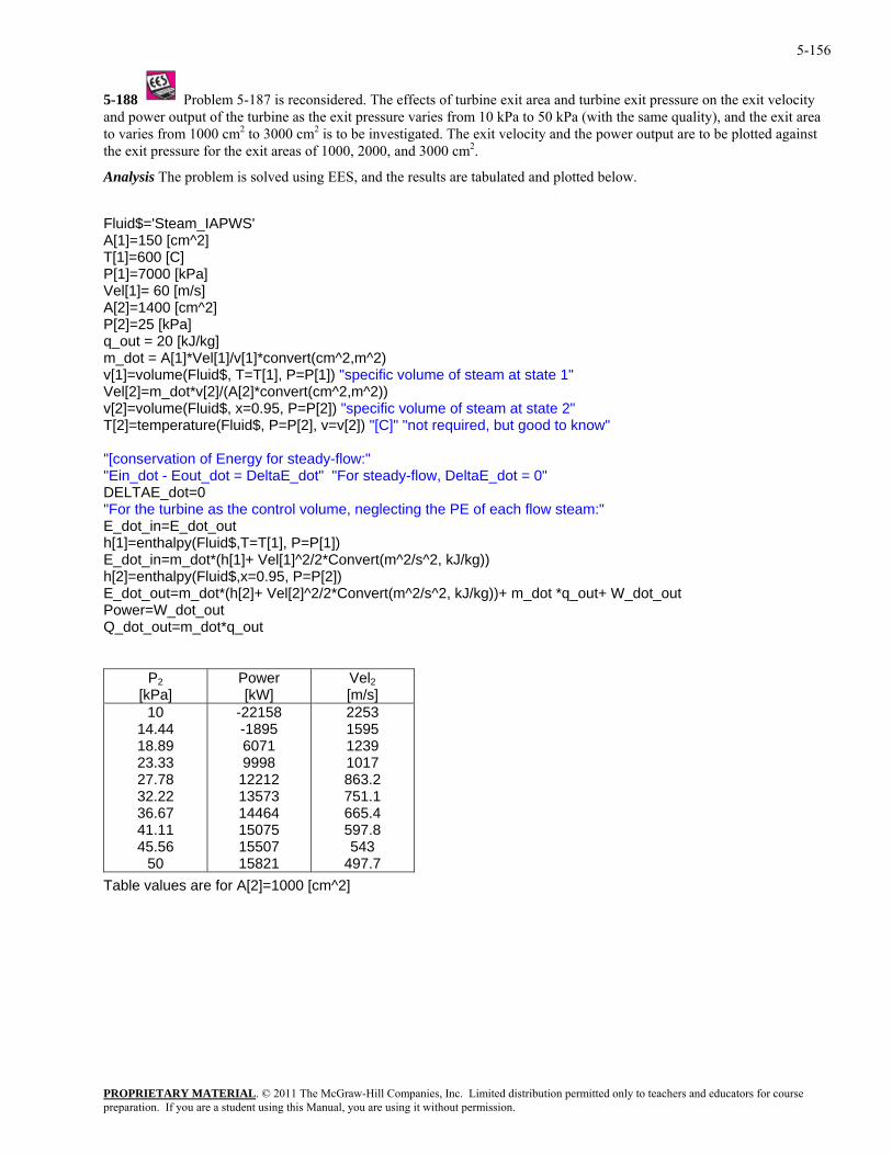
5-156
5-188 Problem 5-187 is reconsidered. The effects of turbine exit area and turbine exit pressure on the exit velocity and power output of the turbine as the exit pressure varies from 10 kPa to 50 kPa (with the same quality), and the exit area to varies from 1000 cm2 to 3000 cm2 is to be investigated. The exit velocity and the power output are to be plotted against the exit pressure for the exit areas of 1000, 2000, and 3000 cm2.
Analysis The problem is solved using EES, and the results are tabulated and plotted below.
Fluid$='Steam_IAPWS' A[1]=150 [cm^2] T[1]=600 [C] P[1]=7000 [kPa] Vel[1]= 60 [m/s] A[2]=1400 [cm^2] P[2]=25 [kPa] q_out = 20 [kJ/kg] m_dot = A[1]*Vel[1]/v[1]*convert(cm^2,m^2) v[1]=volume(Fluid$, T=T[1], P=P[1]) "specific volume of steam at state 1" Vel[2]=m_dot*v[2]/(A[2]*convert(cm^2,m^2)) v[2]=volume(Fluid$, x=0.95, P=P[2]) "specific volume of steam at state 2" T[2]=temperature(Fluid$, P=P[2], v=v[2]) "[C]" "not required, but good to know" "[conservation of Energy for steady-flow:" "Ein_dot - Eout_dot = DeltaE_dot" "For steady-flow, DeltaE_dot = 0" DELTAE_dot=0 "For the turbine as the control volume, neglecting the PE of each flow steam:" E_dot_in=E_dot_out h[1]=enthalpy(Fluid$,T=T[1], P=P[1]) E_dot_in=m_dot*(h[1]+ Vel[1]^2/2*Convert(m^2/s^2, kJ/kg)) h[2]=enthalpy(Fluid$,x=0.95, P=P[2]) E_dot_out=m_dot*(h[2]+ Vel[2]^2/2*Convert(m^2/s^2, kJ/kg))+ m_dot *q_out+ W_dot_out Power=W_dot_out Q_dot_out=m_dot*q_out
P2 [kPa]
Power [kW]
Vel2 [m/s]
10 14.44 18.89 23.33 27.78 32.22 36.67 41.11 45.56
50
-22158 -1895 6071 9998
12212 13573 14464 15075 15507 15821
2253 1595 1239 1017 863.2 751.1 665.4 597.8 543
497.7 Table values are for A[2]=1000 [cm^2]
PROPRIETARY MATERIALpreparation. If you are a student using this Manual, you are using it without permission.
. © 2011 The McGraw-Hill Companies, Inc. Limited distribution permitted only to teachers and educators for course
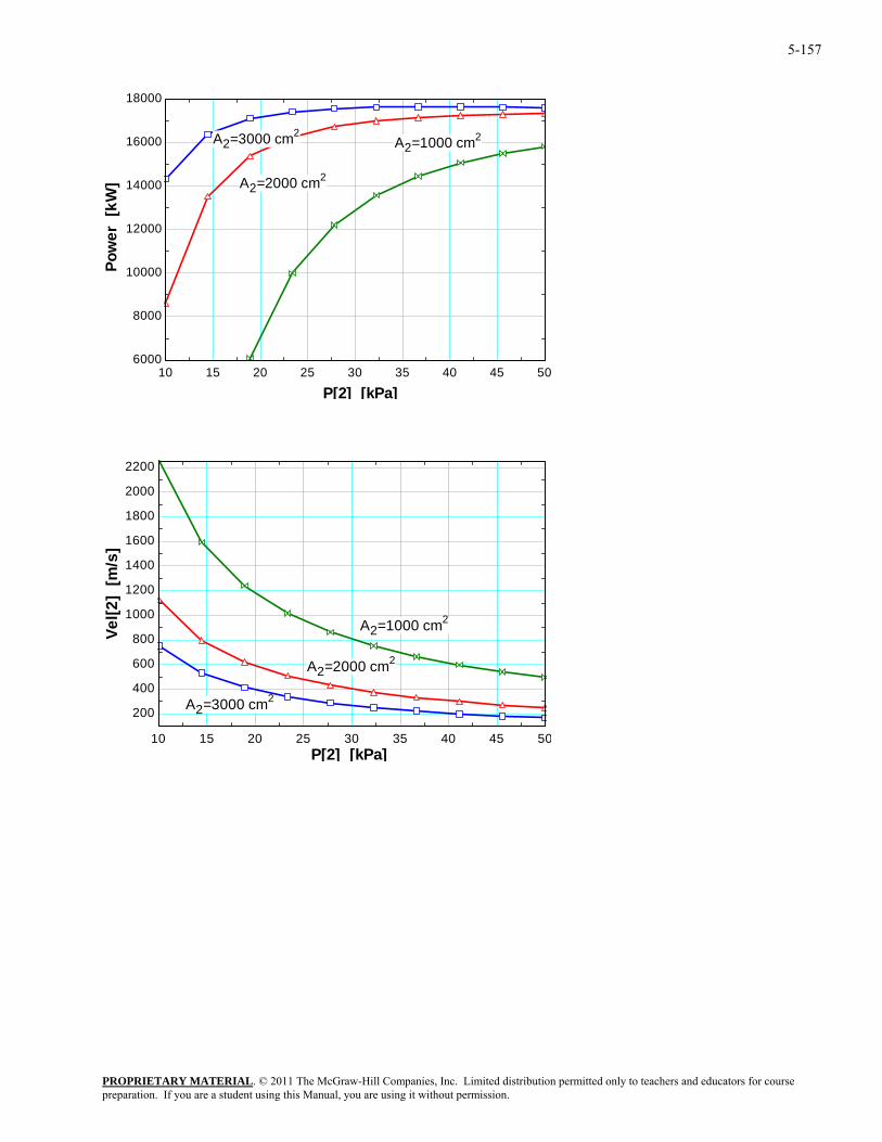
5-157
10 15 20 25 30 35 40 45 506000
8000
10000
12000
14000
16000
18000
P[2] [kPa]
Pow
er [
kW]
A2=3000 cm2
A2=2000 cm2
A2=1000 cm2
10 15 20 25 30 35 40 45 50
200
400
600
800
1000
1200
1400
1600
1800
2000
2200
P[2] [kPa]
Vel[2
] [m
/s]
A2=3000 cm2
A2=2000 cm2
A2=1000 cm2
PROPRIETARY MATERIALpreparation. If you are a student using this Manual, you are using it without permission.
. © 2011 The McGraw-Hill Companies, Inc. Limited distribution permitted only to teachers and educators for course
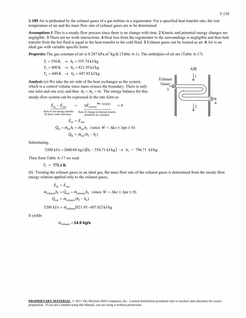
5-158
5-189 Air is preheated by the exhaust gases of a gas turbine in a regenerator. For a specified heat transfer rate, the exit temperature of air and the mass flow rate of exhaust gases are to be determined.
Assumptions 1 This is a steady-flow process since there is no change with time. 2 Kinetic and potential energy changes are negligible. 3 There are no work interactions. 4 Heat loss from the regenerator to the surroundings is negligible and thus heat transfer from the hot fluid is equal to the heat transfer to the cold fluid. 5 Exhaust gases can be treated as air. 6 Air is an ideal gas with variable specific heats.
Properties The gas constant of air is 0.287 kPa.m3/kg.K (Table A-1). The enthalpies of air are (Table A-17)
PROPRIETARY MATERIAL. © 2011 The McGraw-Hill Companies, Inc. Limited distribution permitted only to teachers and educators for course
1 =→= hT
s the system, ry. There is only
ne inlet and one exit, and thus & . The energy balance for this stem can be expressed in the rate form as
outin
energies etc. potential, kinetic, internal,in of te
(steady) 0systemoutin
EE
EEE
=
=∆=−
&&
44 344 21&
43421&&
Substitutin ,
554.71kg/s 800/60kJ/s 3200 2 →−= h h2 = 794.71 kJ/kg
Table A-17 we read
2 . K
(b) Treating the exhaust gases as an ideal gas, the mass flow rate of the exhaust gases is determined from the steady-flow energy relation applied only to the exhaust gases,
It yields
kJ/kg 74.555 K 5501
kJ/kg 02.607 K 600kJ/kg 95.821 K 800
44
33
=→==→=
hThT
Analysis (a) We take the air side of the heat exchanger awhich is a control volume since mass crosses the bounda
AIR
2
1
4
3
Exhaust Gases
& &m m m1 2= =osteady-flow sy
)(
0)peke (since 2air1airin
hhmQ
WhmhmQ
−=
≅∆≅∆==+
&&
&&&&
0
12airin
change Ra
mass and work,heat,by nsferenergy tranet of Rate
g
g ( )( ) kJ/k
Then from
T = 775 1
)(
0)peke (since
43exhaustout
4exhaustout3exhaust
outin
hhmQ
WhmQhm
EE
−=
≅∆≅∆=+=
=
&&
&&&&
&&
( ) kJ/kg 607.02-821.95kJ/s 3200 exhaustm&=
kg/s 14.9=exhaustm&
preparation. If you are a student using this Manual, you are using it without permission.
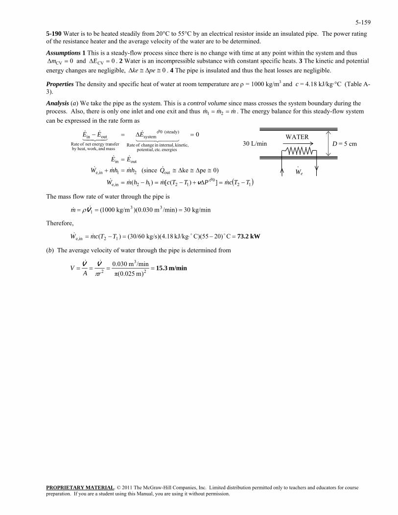
5-159
5-190 Water is to be heated steadily from 20°C to 55°C by an electrical resistor inside an insulated pipe. The power rating of the resistance heater and the average velocity of the water are to be determined.
PROPRIETARY MATERIAL. © 2011 The McGraw-Hill Companies, Inc. Limited distribution permitted only to teachers and educators for course
= 0 negligible.
&
Assumptions 1 This is a steady-flow process since there is no change with time at any point within the system and thus . 2 Water is an incompressible substance with constant specific heats. 3 The kinetic and potential
energy changes are negligible, ∆ke pe≅ ≅ 0 . 4 The pipe is insulated and thus the heat losses are∆ ∆m ECV CV and = 0
∆
Properties The density and specific heat of water at room temperature are ρ = 1000 kg/m3 and c = 4.18 kJ/kg·°C (Table A-3).
Analysis (a) We take the pipe as the system. This is a control volume since mass crosses the system boundary during the process. Also, there is only one inlet and one exit and thus & &m m m1 2= = . The energy balance for this steady-flow system can be expressed in the rate form as
( )120
1212ine,
out21ine,
outin
energies etc. potential, kinetic, internalin change of Rate
systemnsferenergy tranet of Rate
outin 4444 2143421,
(steady) 0
mass and work,heat,by
])([)(
0)peke (since
0
TTcmPTTcmhhmW
QhmhmW
EE
EEE
−=∆+−=−=
≅∆≅∆≅=+
=
=∆=−
&&&&
&&&&
&&
3&&&
v
3)/minm 0.030)(kg/m 1000( 331 === V&& ρm
Therefore,
(b) The average velocity of water through the pipe is determined from
We·
30 L/min D = 5 cmWATER
The mass flow rate of water through the pipe is
0 kg/min
kW73.2 C)2055)(CkJ/kg 4.18)(kg/s 30/60()( 12ine, =−⋅=−= oo&& TTcmW
m/min15.3 )m 0.025(π
/minm 0.0302
3
2 ====rA
VπVV &&
preparation. If you are a student using this Manual, you are using it without permission.
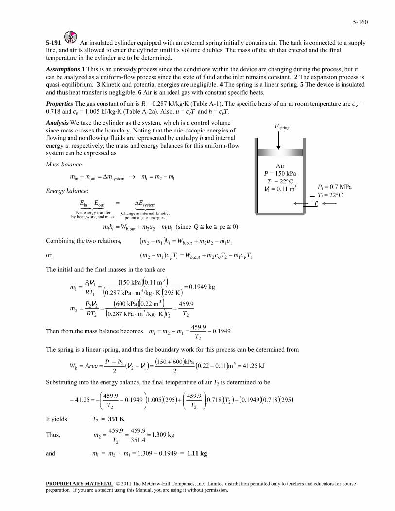
PROPRIETARY MATERIAL. © 2011 The McGraw-Hill Companies, Inc. Limited distribution permitted only to teachers and educators for course preparation. If you are a student using this Manual, you are using it without permission.
5-160
5-191 An insulated cylinder equipped with an external spring initially contains air. The tank is connected to line, and air is allowed to enter the cylinder until i
a supply ts volume doubles. The mass of the air that entered and the final
near spring. 5 The device is insulated
specific heats of air at room temperature are cv =
ass and energy balances for this uniform-flow sed as
Mass balance:
mmmm i
temperature in the cylinder are to be determined.
Assumptions 1 This is an unsteady process since the conditions within the device are changing during the process, but it can be analyzed as a uniform-flow process since the state of fluid at the inlet remains constant. 2 The expansion process is quasi-equilibrium. 3 Kinetic and potential energies are negligible. 4 The spring is a liand thus heat transfer is negligible. 6 Air is an ideal gas with constant specific heats.
Properties The gas constant of air is R = 0.287 kJ/kg·K (Table A-1). The0.718 and cp = 1.005 kJ/kg·K (Table A-2a). Also, u = cvT and h = cpT.
Analysis We take the cylinder as the system, which is a control volume since mass crosses the boundary. Noting that the microscopic energies of flowing and nonflowing fluids are represented by enthalpy h and internal energy u, respectively, the m
Air P = 150 kPaT1 = 22°C
V1 = 0.11 m3 Pi = 0.7 MPa Ti = 22°C
Fspring
system can be expres
outin mm 12system −=→∆=
nergy ba nce:
energies ,kinetic, internal,
system
≅≅≅
∆
Qu
E43421
Combining the two relations,
−
E la
etc.potential in Change
mass and work,heat,by nsferenergy traNet
122outb, −+= mumWhm ii )0peke (since 1
outin =− EE43421
( ) 1122,12 umumWhmm outbi −+=−
o cvr, mWTcmm outbip v 1122,12 )( TcmT −+=−
The initial and the final masses in the tank are
( )( )( )( )
( )( )
( ) 223
2
222
3
K/kgmkPa 0.287
kg 0.1949K 295K/kg
m 0.11
TTRTm =
⋅⋅==
=⋅
31
459.9m 0.22kPa 600P V
311
1 mkPa 0.287kPa 150
RTP
m⋅
==V
Then from the mass balance becomes 1949.09.45912 −=−=
Tmmmi
2
s a lin hus the boundary work for this process can be determined from The spring i ear spring, and t
( ) ( ) ( ) kJ 25.41m0.110.222
Wb kPa6001502
312
21 =−+
=−+
== VVPP
Area
Substituting into the energy balance, the final temperature of air T2 is determined to be
( )( ) ( )( ) ( )( )(295718.01949.0718.09.459295005.11949.09.45925.41 222
−⎟⎟⎠
⎞⎜⎜⎝
⎛+⎟⎟
⎠
⎞⎜⎜⎝
⎛−−=− T
TT )
It yields T2 = 351 K
Thus, kg 309.1351.4459.9459.9
22 ===
Tm
and mi = m2 - m1 = 1.309 − 0.1949 = 1.11 kg
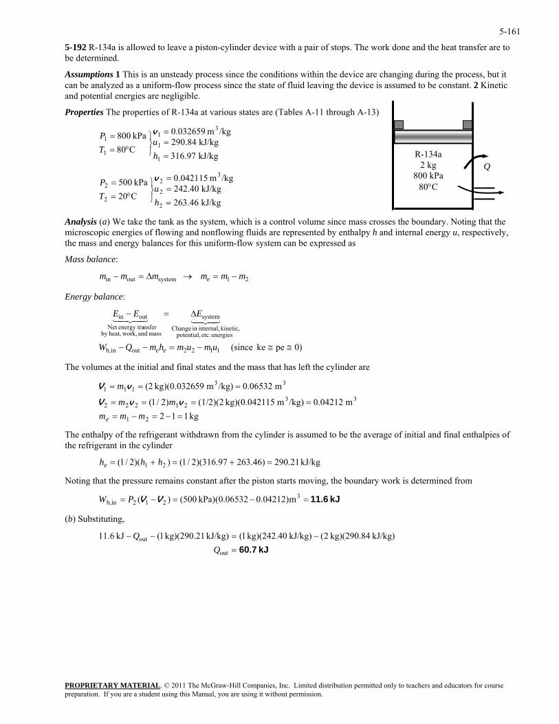
5-161
5-192 R-134a is allowed to leave a piston-cylinder device with a pair of stops. The work done and the heat transfer are to be determined.
Assumptions 1 This is an unsteady process since the conditions within the device are changing during the process, but it can be analyzed as a uniform-flow process since the state of fluid leaving the device is assumed to be constant. 2 Kinetic and potential energies are negligible.
PROPRIETARY MATERIAL. © 2011 The McGraw-Hill Companies, Inc. Limited distribution permitted only to teachers and educators for course
kPa 5003
2 =⎫=P v
he tank as the system, which is a control volume since mass crosses the boundary. Noting that the of flowing and nonflowing fluids are represented by enthalpy h and internal energy u, respectively,
the mass and energy balances for this uniform-flow system can be expressed as
R-134a 2 kg
800 kPa 80°C
Q
Properties The properties of R-134a at various states are (Tables A-11 through A-13)
kJ/kg 97.316kJ/kg 84.290
/kgm 032659.0
C80kPa 800
1
1
31
1
1
===
⎭⎬⎫
°==
hu
TP v
kJ/kg 46.263kJ/kg 40.242
C202
22
2
==
⎭⎬°=
hu
T
/kgm 042115.0
Analysis (a) We take tmicroscopic energies
Mass balance:
21systemoutin mmmmmm e −=→∆=−
Energy balance:
systemoutin
≅≅−=−−
∆=−
umumhmQW
EEE
ee
4342143421
33
33111 === m vV
e refrigerant withdrawn from the cylinder is assumed to be the average of initial and final enthalpies of the cylinder
energies etc. potential, kinetic, internal,in Change
mass and work,heat,by nsferenergy traNet
)0peke (since 1122outinb,
The volumes at the initial and final states and the mass that has left the cylinder are
m 0.06532/kg)m 59kg)(0.0326 (2
kg 112m 0.04212/kg)m 15kg)(0.0421 (1/2)(2)2/1( 21222
=−=−=====
mmmmm vvV
21e
The enthalpy of ththe refrigerant in
kJ/kg 21.290)46.26397.316)(2/1())(2/1( 21 =+=+= hhhe
Noting that the pressure remains constant after the piston starts moving, the boundary work is determined from
(b) Substituting,
kJ 11.6=−=−= 3212inb, m)04212.006532.0(kPa) (500)( VVPW
kJ 60.7=−=−−
out
out kJ/kg) kg)(290.84 2(kJ/kg) kg)(242.40 1(kJ/kg) kg)(290.21 1(kJ 6.11Q
Q
preparation. If you are a student using this Manual, you are using it without permission.
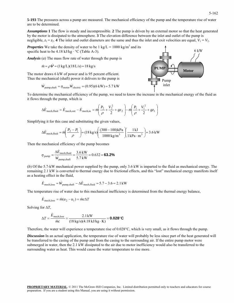
5-162
5-193 The pressures across a pump are measured. The mechanical efficiency of the pump and the temperature rise of water are to be determined.
Assumptions 1 The flow is steady and incompressible. 2 The pump is driven by an external motor so that the heat generated by the motor is dissipated to the atmosphere. 3 The elevation difference between the inlet and outlet of the pump is negligible, z1 = z2. 4 The inlet and outlet diameters are the same and thus the inlet and exit velocities are equal, V1 = V2.
Properties We take the density of water to be 1 kg/L = 1000 kg/m3 and its specific heat to be 4.18 kJ/kg · °C (Table A-3).
PROPRIETARY MATERIAL. © 2011 The McGraw-Hill Companies, Inc. Limited distribution permitted only to teachers and educators for course
Analysis (a) The mass flow rate of water through the pump is
kg/s 18L/s) kg/L)(18 1( === V&& ρm
The motor draws 6 kW of power and is 95 percent efficient. Thus the mechanical (shaft) power it delivers to the pump is
kW 7.5kW) 6)(95.0(electricmotorshaftpump, === WW && η
To determine the mechanical efficiency of the pump, we need to know the increase in the mechanical energy of the fluid as it flows through the pump, which is
PUMP
Pump inlet
Motor
6 kW
⎟⎟⎠
⎞⎜⎜⎝
⎛++−⎟
⎟⎠
⎞⎜⎜ ++=−=∆ 2
22inmech,outmech,fluidmech, 2
gzVP
mEEEρ
&&&&
⎝
⎛1
211
2
2gz
VPm
ρ&
implifying it for this case and substituting the given values,
S
kW 6.3mkPa 1
kJ 1kg/m 1000
300(kg/s) 18(12fluidmech, ⎜
⎜ −=⎟⎟
⎠
⎞⎜⎜⎝
⎛ −=∆
ρPP
mE && kPa)10033
=⎟⎠
⎞⎜⎝
⎛⋅⎟
⎟⎠
⎞
⎝
⎛
Then the mechanical efficiency of the pump becomes
63.2%===∆
=kW 6.3fluidmech,
WE
pump &
&η 632.0
kW 5.7shaftpump,
b) Of the 5.7-kW mechanical power supplied by the pump, only 3.6 kW is imparted to the fluid as mechanical energy. The sts itself
s a heatin effect in the fluid,
ss =−=∆−= EW &&
The temperature rise of water due to this mechanical inefficiency is determined from the thermal energy balance,
(remaining 2.1 kW is converted to thermal energy due to frictional effects, and this “lost” mechanical energy manifea g
lomech,E& kW 1.26.37.5fluidmech,shaftpump,
TcmuumE ∆=−= &&& )( 12lossmech,
Solving for ∆T,
C0.028°=⋅
==∆K)kJ/kg kg/s)(4.18 18(
kW 1.2lossmech,
cmE
T&
&
Therefore, the water will experience a temperature rise of 0.028°C, which is very small, as it flows through the pump.
iscussion In an actual application, the temperature rise of water will probably be less since part of the heat generated will be transferred to the casing of the pump and from the casing to the surrounding air. If the entire pump motor were submerged in water, then the 2.1 kW dissipated to the air due to motor inefficiency would also be transferred to the surrounding water as heat. This would cause the water temperature to rise more.
D
preparation. If you are a student using this Manual, you are using it without permission.
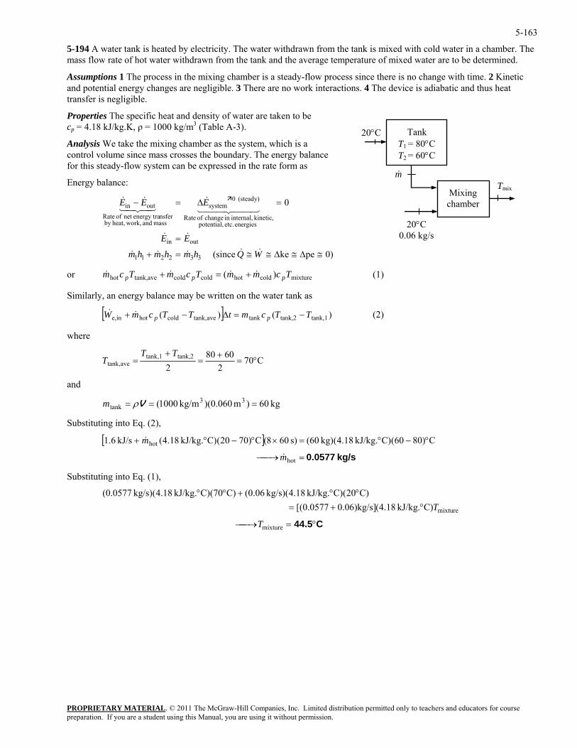
5-163
5-194 A water tank is heated by electricity. The water withdrawn from the tank is mixed with cold water in a chamber. The mass flow rate of hot water withdrawn from the tank and the average temperature of mixed water are to be determined.
Assumptions 1 The process in the mixing chamber is a steady-flow process since there is no change with time. 2 Kinetic and potential energy changes are negligible. 3 There are no work interactions. 4 The device is adiabatic and thus heat transfer is negligible.
Properties The specific heat and density of water are taken to be cp = 4.18 kJ/kg.K, ρ = 1000 kg/m3 (Table A-3).
PROPRIETARY MATERIAL. © 2011 The McGraw-Hill Companies, Inc. Limited distribution permitted only to teachers and educators for course
0
energies etc. potential, kinetic, internal,in change of Rate
(steady) 0system
mass and work,heat,by nsferenergy tranet of Rate
outin
≅∆≅∆≅≅
=∆=−
WQh
EEE
&&
44 344 21&
43421&&
ppp &&&&
20°C
Tmix
20°C 0.06 kg/s
Tank T1 = 80°C T2 = 60°C
Mixing chamber
m&
Analysis We take the mixing chamber as the system, which is a control volume since mass crosses the boundary. The energy balance for this steady-flow system can be expressed in the rate form as
Energy balance:
outin = EE &&
332211 =+ hmmhm &&& 0)peke (since
or m mixturecoldhotcoldcoldavetank,hot )( TcmmTcmTc +=+ (1)
Similarly, an energy balance may be written on the water tank as
(2)
where
[ ] )()( tank,1tank,2tankavetank,coldhotine, TTcmtTTcmW pp −=∆−+ &&
C702
60802
tank,2tank,1=T
T avetank, °=+
=+ T
nd
00 33 =
Substitutin into Eq. (2),
Substituting into Eq. (1),
a
10(tank == Vρm kg 60)m )(0.060kg/m
g
[ ]kg/s 0.0577=⎯→⎯
°−°=×°−°+
hot
hot C)8060(C)kJ/kg. 18.4(kg) (60s) 608(C)7020(C)kJ/kg. 18.4(kJ/s 6.1
m
m
&
&
C44.5°=⎯→⎯
°+=°°+°°
mixture
mixture
C)kJ/kg. 18.4(0.06)kg/s](0.0577[ C)20(C)kJ/kg. 18.4(kg/s) (0.06C)70(C)kJ/kg. 18.4(kg/s) (0.0577
T
T
preparation. If you are a student using this Manual, you are using it without permission.
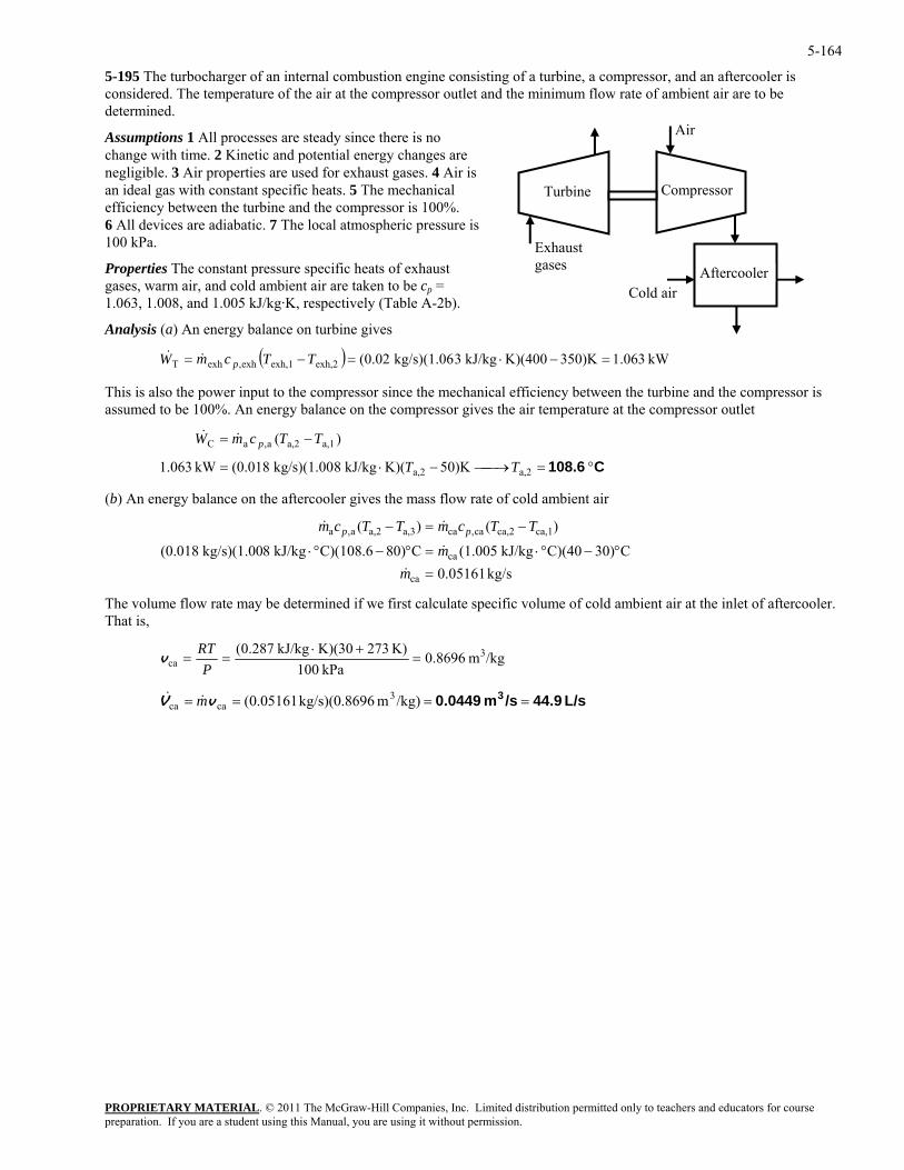
5-164
5-195 The turbocharger of an internal combustion engine consisting of a turbine, a compressor, and an aftercooler is considered. The temperature of the air at the compressor outlet and the minimum flow rate of ambient air are to be determined.
Compressor Turbine
Aftercooler
Exhaust gases
Air
Cold air
Assumptions 1 All processes are steady since there is no change with time. 2 Kinetic and potential energy changes are negligible. 3 Air properties are used for exhaust gases. 4 Air is an ideal gas with constant specific heats. 5 The mechanical efficiency between the turbine and the compressor is 100%. 6 All devices are adiabatic. 7 The local atmospheric pressure is 100 kPa.
Properties The constant pressure specific heats of exhaust gases, warm air, and cold ambient air are taken to be cp = 1.063, 1.008, and 1.005 kJ/kg·K, respectively (Table A-2b).
Analysis (a) An energy balance on turbine gives
( ) kW 063.1350)KK)(400kJ/kg 3kg/s)(1.06 (0.02exh,2exh,1exh,exhT =−⋅=−= TTcmW p&&
This is also the power input to the compressor since the mechanical efficiency between the turbine and the compressor is assumed to be 100%. An energy balance on the compressor gives the air temperature at the compressor outlet
PROPRIETARY MATERIAL. © 2011 The McGraw-Hill Companies, Inc. Limited distribution permitted only to teachers and educators for course
)( TTcmW p&&
(b) An energy balance on the aftercooler gives the mass flow rate of cold ambient air
ca,1ca,2ca,caa,3a,2a,a
°−°⋅=°−°⋅
−=−
m
TTcmTTcm pp
&
&&
he volum flow rate may be determined if we first calculate specific volume of cold ambient air at the inlet of aftercooler.
C 108.6 °=⎯→⎯−⋅= 0)K5K)(kJ/kg 8kg/s)(1.00 (0.018kW 063.1 TT
−=
a,2a,2
a,1a,2a,aC
kg/s 05161.0ca
ca
=m&C0)3C)(40kJ/kg (1.005C0)8C)(108.6kJ/kg 8kg/s)(1.00 (0.018
)()(
T eThat is,
/kgm 8696.0kPa 100
K) 273K)(30kJ/kg 287.0( 3ca =
+⋅==
PRT
v
L/s 44.9/sm 0.0449 3 ==== /kg)m 8696.0kg/s)( 05161.0( 3caca vV m&&
preparation. If you are a student using this Manual, you are using it without permission.
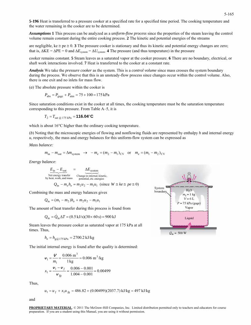
5-165
5-196 Heat is transferred to a pressure cooker at a specified rate for a specified time period. The cooking temperature and the water remaining in the cooker are to be determined.
Assumptions 1 This process can be analyzed as a uniform-flow process since the properties of the steam leaving the control volume remain constant during the entire cooking process. 2 The kinetic and potential energies of the streams
are negligible, ke ≅ pe ≅ 0. 3 The pressure cooker is stationary and thus its kinetic and potential energy changes are zero; that is, ∆KE = ∆PE = 0 and ∆Esystem = ∆Usystem. 4 The pressure (and thus temperature) in the pressure
cooker remains constant. 5 Steam leaves as a saturated vapor at the cooker pressure. 6 There are no boundary, electrical, or shaft work interactions involved. 7 Heat is transferred to the cooker at a constant rate.
Analysis We take the pressure cooker as the system. This is a control volume since mass crosses the system boundary during the process. We observe that this is an unsteady-flow process since changes occur within the control volume. Also, there is one exit and no inlets for mass flow.
(a) The absolute pressure within the cooker is
PROPRIETARY MATERIAL. © 2011 The McGraw-Hill Companies, Inc. Limited distribution permitted only to teachers and educators for course
s =+=+= PPP ab kPa 17510075atmgage
Since saturation conditions exist in the cooker at all times, the cooking temperature must be the saturation temperature corresponding to this pressure. From Table A–5, it is
C116.04°== kPa 175 @sat 2 TT
which is about 16°C higher than the ordinary cooking temperature.
(b) Noting that the microscopic energies of flowing and nonflowing fluids are represented by enthalpy h and internal energy u, respectively, the mass and energy balances for this uniform-flow system can be expressed as
Mass balance:
)(or )( CV21CV12systemoutin mmmmmmmmm ee −=−=−→∆=−
Energy balance:
energies etc. potential, kinetic, internal,in Change
system
mass and work,heat,by nsferenergy traNet
outin
≅≅≅−=−
∆=−
pekeWumumhmQ
EEE4342143421
ombining the mass and energy balances gives
The amount of heat transfer during this process is found from
the pressure cooker as saturated vapor at 175 kPa at all mes. Thus,
The initial internal energy is found after the quality is determined:
)0 (since 1122in ee
C
112221in )( umumhmmQ e −+−=
kJ 900s) 60kJ/s)(30 5.0(inin =×=∆= TQQ &
Steam leaves ti
kJ/kg 2.2700kPa 175 @g == hhe
00499.0001.01.004001.00.006
/kgm 0.006kg 1
m 0.006
11
33
11
=−−
=−
=
===
fg
fx
m
v
vv
Vv
Thus,
kJ/kg 497kJ/kg )7.2037)(00499.0(82.48611 =+=+= fgf uxuu
and
preparation. If you are a student using this Manual, you are using it without permission.
5-166 kJ 497kJ/kg) 497)(kg 1(111 === umU
PROPRIETARY MATERIAL. © 2011 The McGraw-Hill Companies, Inc. Limited distribution permitted only to teachers and educators for course
he mass of the system at the final state is m2 = V /v2. Substituting this into the energy equation yields T
⎟⎟⎠
⎞⎜⎜⎝
⎛−+⎟⎟
⎠
⎞⎜⎜⎝
⎛−= 112
221in umuhmQ e v
VvV
There are two unknowns in this equation, u2 and v2. Thus we need to relate them to a single unknown before we can etermine these unknowns. Assuming there is still some liquid water left in the cooker at the final state (i.e., saturation
conditions exist), v2 and u2 can be expressed as
fg
ecall tha uring a boiling process at constant pressure, the properties of each phase remain constant (only the amounts ). When these expressions are substituted into the above energy equation, x2 becomes the only unknown, and it is ined to be
,
33 =−v
d
kJ/kg )7.2037(82.486
/kgm )001.0004.1(001.0
2
3222
xuxuu
xx
f
fgf
+=+=
−+=+= vvv
22
R t dchangedeterm
009.02 =x
Thus
/kgm 0.010/kgm )001.0004.1)(009.0(001.0 +=2
and
kg 0.6===/kgm 0.01
m 0.0063
3
22 v
Vm
Therefore, after 30 min there is 0.6 kg water (liquid + vapor) left in the pressure cooker.
Discussion Note that almost half of the water in the pressure cooker has evaporated during cooking.
preparation. If you are a student using this Manual, you are using it without permission.
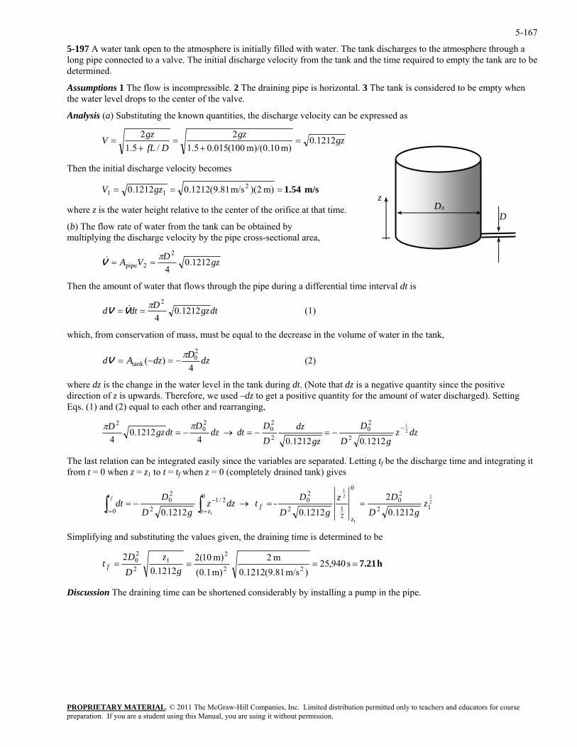
5-167
5-197 A water tank open to the atmosphere is initially filled with water. The tank discharges to the atmosphere through a long pipe connected to a valve. The initial discharge velocity from the tank and the time required to empty the tank are to be determined.
Assumptions 1 The flow is incompressible. 2 The draining pipe is horizontal. 3 The tank is considered to be empty when the water level drops to the center of the valve.
Analysis (a) Substituting the known quantities, the discharge velocity can be expressed as
gzgz
DfLgz
V 1212.0m) m)/(0.10 100(015.05.1
2/5.1
2=
+=
+=
DD0
Then the initial discharge velocity becomes
m/s 1.54=== m) 2)(m/s 81.9(1212.01212.0 211 gzV
zwhere z is the water height relative to the center of the orifice at th
(b) The flow rate of water from the tank can be obtained by multiplying the discharge velocity by the pipe cross-sectional area,
at time.
gzDVA 1212.04
2
2pipeπ
==V&
Then the am er t ows through the pipe during a differential time interval dt is ount of wat hat fl
dtgzDdtd 1212.04
π==VV & (1)
2
which, from conservation of mass, mu e of water in the tank, st be equal to the decrease in the volum
dzDdzAd4
)( 0tank
π−=−=V (2)
where dz is the change in the water level in the tank d
2
uring dt. (Note that dz is a negative quantity since the positive direction o is upwards. Therefore, we used –dz to get a positive quantity for the amount of water discharged). Setting Eqs. (1) and (2) equal to each other and rearranging,
f z
dzzgD
D
gzdzD
dtdzD
dtgzD 1
1212.022
020
2−=−=→−=
ππD
2
1212.01212.044 20
2−
The last relation can be integrated easily since the variables are separated. Letting tf be the discharge time and integrating it from t = 0 when z = z1 to t = tf when z = 0 (completely drained tank) gives
212
1 0200 2/1
20 2zDDt f −
1z1
12
20
21220 1212.01212.0
- 1212.0
zgD
D
gDtdzz
gDdt f
zz==→−= ∫∫ =
Simplifying and substituting the values given, the draining time is determined to be
t=
h 7.21 ==== s 940,25)m/s 81.9(1212.0
m 2m) 1.0(m) 10(2
1212.02
22
21
2
20
gz
DD
t f
Discussion The draining time can be shortened considerably by installing a pump in the pipe.
PROPRIETARY MATERIALpreparation. If you are a student using this Manual, you are using it without permission.
. © 2011 The McGraw-Hill Companies, Inc. Limited distribution permitted only to teachers and educators for course
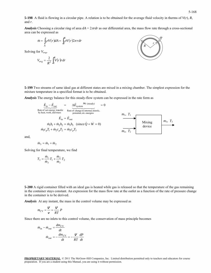
5-168
5-198 A fluid is flowing in a circular pipe. A relation is to be obtained for the average fluid velocity in therms of V(r), R, and r.
Analysis Choosing a circular ring of area dA = 2πrdr as our differential area, the mass flow rate through a cross-sectional area can be expressed as
dr
r R
( ) ( )∫∫ ==R
A
drrrVdArVm0
2πρρ&
Solving for Vavg,
( ) drrrVR
VR
∫=02avg
2
5-199 Two streams of same ideal gas at different states are mixed in a mixing chamber. The simplest expression for the
Analysis The energy balance for this steady-flow system can be expressed in the rate form as
and,
olving for final temperature, we find
mixture temperature in a specified format is to be obtained.
332211
332211
outin
energies etc. potential, kinetic, internal,in change of Rate
(steady) 0system
mass and work,heat,by nsferenergy tranet of Rate
outin
)0 (since
0
TcmTcmTcmWQhmhmhm
EE
EEE
ppp &&&
&&&&&
&&
44 344 21&
43421&&
=+===+
=
=∆=−
m1, T1
m2, T2
m3, T3 Mixing device
213 mmm &&& +=
S
23
21
3
13 T
mm
Tmm
T&
&
&
&+=
5-200 A rigid container filled with an ideal gas is heated while gas is released so that the temperature of the gas remaining in the container stays constant. An expression for the mass flow rate at the outlet as a function of the rate of pressure change
nalysis At any instant, the mass in the control volume may be expressed as
in the container is to be derived.
A
PROPRIETARY MATERIAL. © 2011 The McGraw-Hill Companies, Inc. Limited distribution permitted only to teachers and educators for course
Pm VV==
RTvCV
ince there are no inlets to this control volume, the conservation of mass principle becomes
S
dtdP
RTdtdm
m
dtdm
mm
V−=−=
=−
CVout
CVoutin
&
&&
preparation. If you are a student using this Manual, you are using it without permission.
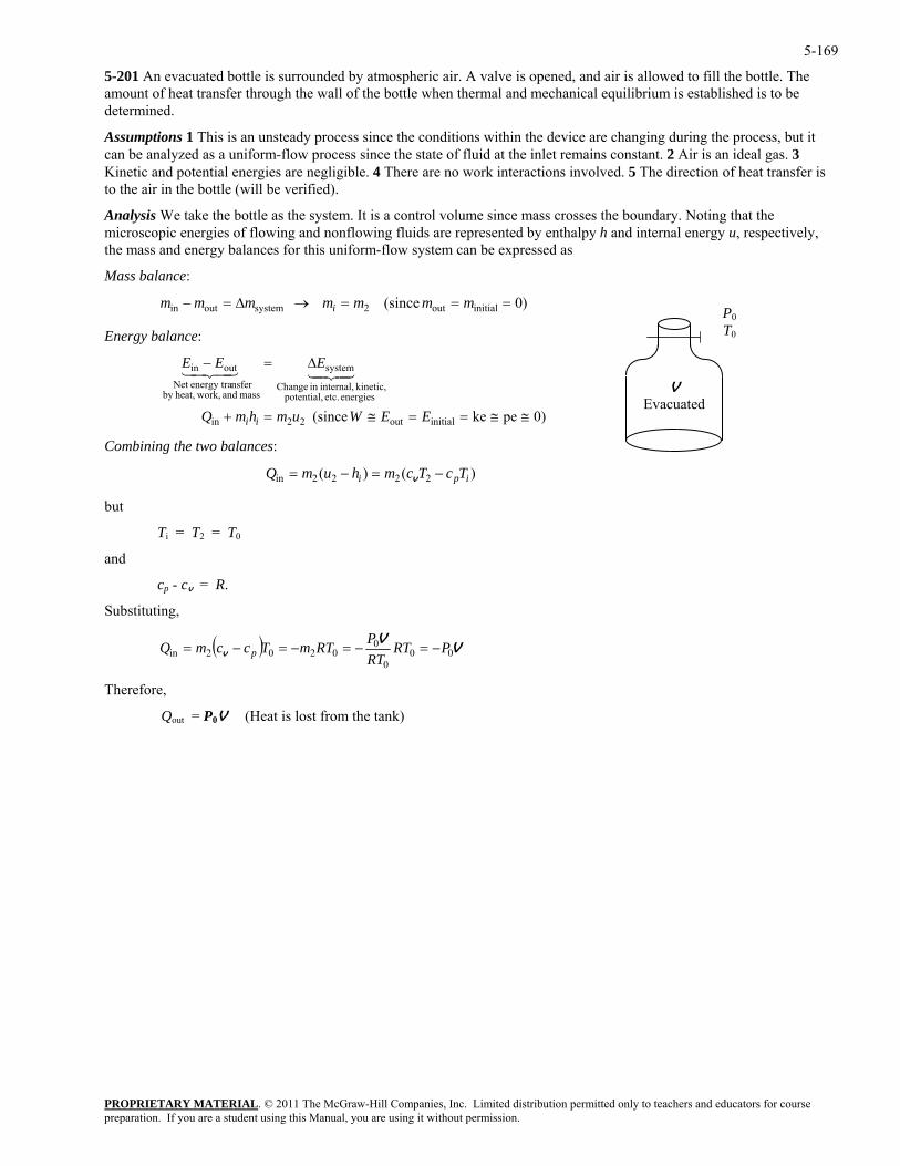
5-169
5-201 An evacuated bottle is surrounded by atmospheric air. A valve is opened, and air is allowed to fill the bottle. The amount of heat transfer through the wall of the bottle when thermal and mechanical equilibrium is established is to be determined.
Assumptions 1 This is an unsteady process since the conditions within the device are changing during the process, but it can be analyzed as a uniform-flow process since the state of fluid at the inlet remains constant. 2 Air is an ideal gas. 3 Kinetic and potential energies are negligible. 4 There are no work interactions involved. 5 The direction of heat transfer is to the air in the bottle (will be verified).
Analysis We take the bottle as the system. It is a control volume since mass crosses the boundary. Noting that the microscopic energies of flowing and nonflowing fluids are represented by enthalpy h and internal energy u, respectively, the mass and energy balances for this uniform-flow system can be expressed as
Mass balance:
)0 (since initialout2systemoutin ===→∆=− mmmmmmm i P0 T0
V Evacuated
Energy balance:
)0peke (since initialout22in
energies etc. potential, kinetic, internal,in Change
system
mass and work,heat,by nsferenergy traNet
outin
≅≅==≅=+
∆=−
EEWumhmQ
EEE
ii
4342143421
Combining the two balances:
)()( 2222in ipi TcTcmhumQ −=−= v
but
Ti = T2 = T0
and
v = R.
Substituting,
cp - c
( ) VV
v 000
00202in PRT
RTPRTmTccmQ p −=−=−=−=
Therefor
Qout = P0V (Heat is lost from the tank)
e,
PROPRIETARY MATERIALpreparation. If you are a student using this Manual, you are using it without permission.
. © 2011 The McGraw-Hill Companies, Inc. Limited distribution permitted only to teachers and educators for course
5-170
Fundamentals of Engineering (FE) Exam Problems
5-202 Steam is accelerated by a nozzle steadily from a low velocity to a velocity of 280 m/s at a rate of 2.5 kg/s. If the temperature and pressure of the steam at the nozzle exit are 400°C and 2 MPa, the exit area of the nozzle is
(a) 8.4 cm2 (b) 10.7 cm2 (c) 13.5 cm2 (d) 19.6 cm2 (e) 23.0 cm2
Answer (c) 13.5 cm2
Solution Solved by EES Software. Solutions can be verified by copying-and-pasting the following lines on a blank EES screen. (Similar problems and their solutions can be obtained easily by modifying numerical values).
Vel_1=0 "m/s" Vel_2=280 "m/s" m=2.5 "kg/s" T2=400 "C" P2=2000 "kPa" "The rate form of energy balance is E_dot_in - E_dot_out = DELTAE_dot_cv" v2=VOLUME(Steam_IAPWS,T=T2,P=P2) m=(1/v2)*A2*Vel_2 "A2 in m^2" "Some Wrong Solutions with Common Mistakes:" R=0.4615 "kJ/kg.K" P2*v2ideal=R*(T2+273) m=(1/v2ideal)*W1_A2*Vel_2 "assuming ideal gas" P1*v2ideal=R*T2 m=(1/v2ideal)*W2_A2*Vel_2 "assuming ideal gas and using C" m=W3_A2*Vel_2 "not using specific volume"
PROPRIETARY MATERIALpreparation. If you are a student using this Manual, you are using it without permission.
. © 2011 The McGraw-Hill Companies, Inc. Limited distribution permitted only to teachers and educators for course
5-171
5-203 Steam enters a diffuser steadily at 0.5 MPa, 300°C, and 122 m/s at a rate of 3.5 kg/s. The inlet area of the diffuser is
(a) 15 cm2 (b) 50 cm2 (c) 105 cm2 (d) 150 cm2 (e) 190 cm2
Answer (d) 150 cm2
Solution Solved by EES Software. Solutions can be verified by copying-and-pasting the following lines on a blank EES screen. (Similar problems and their solutions can be obtained easily by modifying numerical values).
Vel_1=122 "m/s" m=3.5 "kg/s" T1=300 "C" P1=500 "kPa" "The rate form of energy balance is E_dot_in - E_dot_out = DELTAE_dot_cv" v1=VOLUME(Steam_IAPWS,T=T1,P=P1) m=(1/v1)*A*Vel_1 "A in m^2" "Some Wrong Solutions with Common Mistakes:" R=0.4615 "kJ/kg.K" P1*v1ideal=R*(T1+273) m=(1/v1ideal)*W1_A*Vel_1 "assuming ideal gas" P1*v2ideal=R*T1 m=(1/v2ideal)*W2_A*Vel_1 "assuming ideal gas and using C" m=W3_A*Vel_1 "not using specific volume"
5-204 An adiabatic heat exchanger is used to heat cold water at 15°C entering at a rate of 5 kg/s by hot air at 90°C entering also at rate of 5 kg/s. If the exit temperature of hot air is 20°C, the exit temperature of cold water is
(a) 27°C (b) 32°C (c) 52°C (d) 85°C (e) 90°C
Answer (b) 32°C
Solution Solved by EES Software. Solutions can be verified by copying-and-pasting the following lines on a blank EES screen. (Similar problems and their solutions can be obtained easily by modifying numerical values).
C_w=4.18 "kJ/kg-C" Cp_air=1.005 "kJ/kg-C" Tw1=15 "C" m_dot_w=5 "kg/s" Tair1=90 "C" Tair2=20 "C" m_dot_air=5 "kg/s" "The rate form of energy balance for a steady-flow system is E_dot_in = E_dot_out" m_dot_air*Cp_air*(Tair1-Tair2)=m_dot_w*C_w*(Tw2-Tw1) "Some Wrong Solutions with Common Mistakes:" (Tair1-Tair2)=(W1_Tw2-Tw1) "Equating temperature changes of fluids" Cv_air=0.718 "kJ/kg.K" m_dot_air*Cv_air*(Tair1-Tair2)=m_dot_w*C_w*(W2_Tw2-Tw1) "Using Cv for air" W3_Tw2=Tair1 "Setting inlet temperature of hot fluid = exit temperature of cold fluid" W4_Tw2=Tair2 "Setting exit temperature of hot fluid = exit temperature of cold fluid"
PROPRIETARY MATERIALpreparation. If you are a student using this Manual, you are using it without permission.
. © 2011 The McGraw-Hill Companies, Inc. Limited distribution permitted only to teachers and educators for course
5-172
5-205 A heat exchanger is used to heat cold water at 15°C entering at a rate of 2 kg/s by hot air at 85°C entering at rate of 3 kg/s. The heat exchanger is not insulated, and is loosing heat at a rate of 25 kJ/s. If the exit temperature of hot air is 20°C, the exit temperature of cold water is
(a) 28°C (b) 35°C (c) 38°C (d) 41°C (e) 80°C
Answer (b) 35°C
Solution Solved by EES Software. Solutions can be verified by copying-and-pasting the following lines on a blank EES screen. (Similar problems and their solutions can be obtained easily by modifying numerical values).
C_w=4.18 "kJ/kg-C" Cp_air=1.005 "kJ/kg-C" Tw1=15 "C" m_dot_w=2 "kg/s" Tair1=85 "C" Tair2=20 "C" m_dot_air=3 "kg/s" Q_loss=25 "kJ/s" "The rate form of energy balance for a steady-flow system is E_dot_in = E_dot_out" m_dot_air*Cp_air*(Tair1-Tair2)=m_dot_w*C_w*(Tw2-Tw1)+Q_loss "Some Wrong Solutions with Common Mistakes:" m_dot_air*Cp_air*(Tair1-Tair2)=m_dot_w*C_w*(W1_Tw2-Tw1) "Not considering Q_loss" m_dot_air*Cp_air*(Tair1-Tair2)=m_dot_w*C_w*(W2_Tw2-Tw1)-Q_loss "Taking heat loss as heat gain" (Tair1-Tair2)=(W3_Tw2-Tw1) "Equating temperature changes of fluids" Cv_air=0.718 "kJ/kg.K" m_dot_air*Cv_air*(Tair1-Tair2)=m_dot_w*C_w*(W4_Tw2-Tw1)+Q_loss "Using Cv for air"
5-206 An adiabatic heat exchanger is used to heat cold water at 15°C entering at a rate of 5 kg/s by hot water at 90°C entering at rate of 4 kg/s. If the exit temperature of hot water is 50°C, the exit temperature of cold water is
(a) 42°C (b) 47°C (c) 55°C (d) 78°C (e) 90°C
Answer (b) 47°C
Solution Solved by EES Software. Solutions can be verified by copying-and-pasting the following lines on a blank EES screen. (Similar problems and their solutions can be obtained easily by modifying numerical values).
C_w=4.18 "kJ/kg-C" Tcold_1=15 "C" m_dot_cold=5 "kg/s" Thot_1=90 "C" Thot_2=50 "C" m_dot_hot=4 "kg/s" Q_loss=0 "kJ/s" "The rate form of energy balance for a steady-flow system is E_dot_in = E_dot_out" m_dot_hot*C_w*(Thot_1-Thot_2)=m_dot_cold*C_w*(Tcold_2-Tcold_1)+Q_loss "Some Wrong Solutions with Common Mistakes:" Thot_1-Thot_2=W1_Tcold_2-Tcold_1 "Equating temperature changes of fluids" W2_Tcold_2=90 "Taking exit temp of cold fluid=inlet temp of hot fluid"
PROPRIETARY MATERIALpreparation. If you are a student using this Manual, you are using it without permission.
. © 2011 The McGraw-Hill Companies, Inc. Limited distribution permitted only to teachers and educators for course
5-173
5-207 In a shower, cold water at 10°C flowing at a rate of 5 kg/min is mixed with hot water at 60°C flowing at a rate of 2 kg/min. The exit temperature of the mixture will be
(a) 24.3°C (b) 35.0°C (c) 40.0°C (d) 44.3°C (e) 55.2°C
Answer (a) 24.3°C
Solution Solved by EES Software. Solutions can be verified by copying-and-pasting the following lines on a blank EES screen. (Similar problems and their solutions can be obtained easily by modifying numerical values).
C_w=4.18 "kJ/kg-C" Tcold_1=10 "C" m_dot_cold=5 "kg/min" Thot_1=60 "C" m_dot_hot=2 "kg/min" "The rate form of energy balance for a steady-flow system is E_dot_in = E_dot_out" m_dot_hot*C_w*Thot_1+m_dot_cold*C_w*Tcold_1=(m_dot_hot+m_dot_cold)*C_w*Tmix "Some Wrong Solutions with Common Mistakes:" W1_Tmix=(Tcold_1+Thot_1)/2 "Taking the average temperature of inlet fluids"
5-208 In a heating system, cold outdoor air at 7°C flowing at a rate of 4 kg/min is mixed adiabatically with heated air at 70°C flowing at a rate of 3 kg/min. The exit temperature of the mixture is
(a) 34°C (b) 39°C (c) 45°C (d) 63°C (e) 77°C
Answer (a) 34°C
Solution Solved by EES Software. Solutions can be verified by copying-and-pasting the following lines on a blank EES screen. (Similar problems and their solutions can be obtained easily by modifying numerical values).
C_air=1.005 "kJ/kg-C" Tcold_1=7 "C" m_dot_cold=4 "kg/min" Thot_1=70 "C" m_dot_hot=3 "kg/min" "The rate form of energy balance for a steady-flow system is E_dot_in = E_dot_out" m_dot_hot*C_air*Thot_1+m_dot_cold*C_air*Tcold_1=(m_dot_hot+m_dot_cold)*C_air*Tmix "Some Wrong Solutions with Common Mistakes:" W1_Tmix=(Tcold_1+Thot_1)/2 "Taking the average temperature of inlet fluids"
PROPRIETARY MATERIALpreparation. If you are a student using this Manual, you are using it without permission.
. © 2011 The McGraw-Hill Companies, Inc. Limited distribution permitted only to teachers and educators for course
5-174
5-209 Hot combustion gases (assumed to have the properties of air at room temperature) enter a gas turbine at 1 MPa and 1500 K at a rate of 0.1 kg/s, and exit at 0.2 MPa and 900 K. If heat is lost from the turbine to the surroundings at a rate of 15 kJ/s, the power output of the gas turbine is
(a) 15 kW (b) 30 kW (c) 45 kW (d) 60 kW (e) 75 kW
Answer (c) 45 kW
Solution Solved by EES Software. Solutions can be verified by copying-and-pasting the following lines on a blank EES screen. (Similar problems and their solutions can be obtained easily by modifying numerical values).
Cp_air=1.005 "kJ/kg-C" T1=1500 "K" T2=900 "K" m_dot=0.1 "kg/s" Q_dot_loss=15 "kJ/s" "The rate form of energy balance for a steady-flow system is E_dot_in = E_dot_out" W_dot_out+Q_dot_loss=m_dot*Cp_air*(T1-T2) "Alternative: Variable specific heats - using EES data" W_dot_outvariable+Q_dot_loss=m_dot*(ENTHALPY(Air,T=T1)-ENTHALPY(Air,T=T2)) "Some Wrong Solutions with Common Mistakes:" W1_Wout=m_dot*Cp_air*(T1-T2) "Disregarding heat loss" W2_Wout-Q_dot_loss=m_dot*Cp_air*(T1-T2) "Assuming heat gain instead of loss"
5-210 Steam expands in a turbine from 4 MPa and 500°C to 0.5 MPa and 250°C at a rate of 1350 kg/h. Heat is lost from the turbine at a rate of 25 kJ/s during the process. The power output of the turbine is
(a) 157 kW (b) 207 kW (c) 182 kW (d) 287 kW (e) 246 kW
Answer (a) 157 kW
Solution Solved by EES Software. Solutions can be verified by copying-and-pasting the following lines on a blank EES screen. (Similar problems and their solutions can be obtained easily by modifying numerical values).
T1=500 "C" P1=4000 "kPa" T2=250 "C" P2=500 "kPa" m_dot=1350/3600 "kg/s" Q_dot_loss=25 "kJ/s" h1=ENTHALPY(Steam_IAPWS,T=T1,P=P1) h2=ENTHALPY(Steam_IAPWS,T=T2,P=P2) "The rate form of energy balance for a steady-flow system is E_dot_in = E_dot_out" W_dot_out+Q_dot_loss=m_dot*(h1-h2) "Some Wrong Solutions with Common Mistakes:" W1_Wout=m_dot*(h1-h2) "Disregarding heat loss" W2_Wout-Q_dot_loss=m_dot*(h1-h2) "Assuming heat gain instead of loss" u1=INTENERGY(Steam_IAPWS,T=T1,P=P1) u2=INTENERGY(Steam_IAPWS,T=T2,P=P2) W3_Wout+Q_dot_loss=m_dot*(u1-u2) "Using internal energy instead of enthalpy" W4_Wout-Q_dot_loss=m_dot*(u1-u2) "Using internal energy and wrong direction for heat"
PROPRIETARY MATERIALpreparation. If you are a student using this Manual, you are using it without permission.
. © 2011 The McGraw-Hill Companies, Inc. Limited distribution permitted only to teachers and educators for course
5-175
5-211 Steam is compressed by an adiabatic compressor from 0.2 MPa and 150°C to 0.8 MPa and 350°C at a rate of 1.30 kg/s. The power input to the compressor is
(a) 511 kW (b) 393 kW (c) 302 kW (d) 717 kW (e) 901 kW
Answer (a) 511 kW
Solution Solved by EES Software. Solutions can be verified by copying-and-pasting the following lines on a blank EES screen. (Similar problems and their solutions can be obtained easily by modifying numerical values).
P1=200 "kPa" T1=150 "C" P2=800 "kPa" T2=350 "C" m_dot=1.30 "kg/s" Q_dot_loss=0 "kJ/s" h1=ENTHALPY(Steam_IAPWS,T=T1,P=P1) h2=ENTHALPY(Steam_IAPWS,T=T2,P=P2) "The rate form of energy balance for a steady-flow system is E_dot_in = E_dot_out" W_dot_in-Q_dot_loss=m_dot*(h2-h1) "Some Wrong Solutions with Common Mistakes:" W1_Win-Q_dot_loss=(h2-h1)/m_dot "Dividing by mass flow rate instead of multiplying" W2_Win-Q_dot_loss=h2-h1 "Not considering mass flow rate" u1=INTENERGY(Steam_IAPWS,T=T1,P=P1) u2=INTENERGY(Steam_IAPWS,T=T2,P=P2) W3_Win-Q_dot_loss=m_dot*(u2-u1) "Using internal energy instead of enthalpy" W4_Win-Q_dot_loss=u2-u1 "Using internal energy and ignoring mass flow rate"
PROPRIETARY MATERIALpreparation. If you are a student using this Manual, you are using it without permission.
. © 2011 The McGraw-Hill Companies, Inc. Limited distribution permitted only to teachers and educators for course
5-176
5-212 Refrigerant-134a is compressed by a compressor from the saturated vapor state at 0.14 MPa to 0.9 MPa and 60°C at a rate of 0.108 kg/s. The refrigerant is cooled at a rate of 1.10 kJ/s during compression. The power input to the compressor is
(a) 4.94 kW (b) 6.04 kW (c) 7.14 kW (d) 7.50 kW (e) 8.13 kW
Answer (c) 7.14 kW
Solution Solved by EES Software. Solutions can be verified by copying-and-pasting the following lines on a blank EES screen. (Similar problems and their solutions can be obtained easily by modifying numerical values).
P1=140 "kPa" x1=1 P2=900 "kPa" T2=60 "C" m_dot=0.108 "kg/s" Q_dot_loss=1.10 "kJ/s" h1=ENTHALPY(R134a,x=x1,P=P1) h2=ENTHALPY(R134a,T=T2,P=P2) "The rate form of energy balance for a steady-flow system is E_dot_in = E_dot_out" W_dot_in-Q_dot_loss=m_dot*(h2-h1) "Some Wrong Solutions with Common Mistakes:" W1_Win+Q_dot_loss=m_dot*(h2-h1) "Wrong direction for heat transfer" W2_Win =m_dot*(h2-h1) "Not considering heat loss" u1=INTENERGY(R134a,x=x1,P=P1) u2=INTENERGY(R134a,T=T2,P=P2) W3_Win-Q_dot_loss=m_dot*(u2-u1) "Using internal energy instead of enthalpy" W4_Win+Q_dot_loss=u2-u1 "Using internal energy and wrong direction for heat transfer"
PROPRIETARY MATERIALpreparation. If you are a student using this Manual, you are using it without permission.
. © 2011 The McGraw-Hill Companies, Inc. Limited distribution permitted only to teachers and educators for course
5-177
5-213 Refrigerant-134a expands in an adiabatic turbine from 1.2 MPa and 100°C to 0.18 MPa and 50°C at a rate of 1.25 kg/s. The power output of the turbine is
(a) 46.3 kW (b) 66.4 kW (c) 72.7 kW (d) 89.2 kW (e) 112.0 kW
Answer (a) 46.3 kW
Solution Solved by EES Software. Solutions can be verified by copying-and-pasting the following lines on a blank EES screen. (Similar problems and their solutions can be obtained easily by modifying numerical values). P1=1200 "kPa" T1=100 "C" P2=180 "kPa" T2=50 "C" m_dot=1.25 "kg/s" Q_dot_loss=0 "kJ/s" h1=ENTHALPY(R134a,T=T1,P=P1) h2=ENTHALPY(R134a,T=T2,P=P2) "The rate form of energy balance for a steady-flow system is E_dot_in = E_dot_out" -W_dot_out-Q_dot_loss=m_dot*(h2-h1) "Some Wrong Solutions with Common Mistakes:" -W1_Wout-Q_dot_loss=(h2-h1)/m_dot "Dividing by mass flow rate instead of multiplying" -W2_Wout-Q_dot_loss=h2-h1 "Not considering mass flow rate" u1=INTENERGY(R134a,T=T1,P=P1) u2=INTENERGY(R134a,T=T2,P=P2) -W3_Wout-Q_dot_loss=m_dot*(u2-u1) "Using internal energy instead of enthalpy" -W4_Wout-Q_dot_loss=u2-u1 "Using internal energy and ignoring mass flow rate"
5-214 Refrigerant-134a at 1.4 MPa and 90°C is throttled to a pressure of 0.6 MPa. The temperature of the refrigerant after throttling is
(a) 22°C (b) 56°C (c) 82°C (d) 80°C (e) 90.0°C
Answer (d) 80°C
Solution Solved by EES Software. Solutions can be verified by copying-and-pasting the following lines on a blank EES screen. (Similar problems and their solutions can be obtained easily by modifying numerical values).
P1=1400 "kPa" T1=90 "C" P2=600 "kPa" h1=ENTHALPY(R134a,T=T1,P=P1) T2=TEMPERATURE(R134a,h=h1,P=P2) "Some Wrong Solutions with Common Mistakes:" W1_T2=T1 "Assuming the temperature to remain constant" W2_T2=TEMPERATURE(R134a,x=0,P=P2) "Taking the temperature to be the saturation temperature at P2" u1=INTENERGY(R134a,T=T1,P=P1) W3_T2=TEMPERATURE(R134a,u=u1,P=P2) "Assuming u=constant" v1=VOLUME(R134a,T=T1,P=P1) W4_T2=TEMPERATURE(R134a,v=v1,P=P2) "Assuming v=constant"
PROPRIETARY MATERIALpreparation. If you are a student using this Manual, you are using it without permission.
. © 2011 The McGraw-Hill Companies, Inc. Limited distribution permitted only to teachers and educators for course
5-178
5-215 Air at 27°C and 5 atm is throttled by a valve to 1 atm. If the valve is adiabatic and the change in kinetic energy is negligible, the exit temperature of air will be
(a) 10°C (b) 15°C (c) 20°C (d) 23°C (e) 27°C
Answer (e) 27°C
Solution Solved by EES Software. Solutions can be verified by copying-and-pasting the following lines on a blank EES screen. (Similar problems and their solutions can be obtained easily by modifying numerical values).
"The temperature of an ideal gas remains constant during throttling, and thus T2=T1" T1=27 "C" P1=5 "atm" P2=1 "atm" T2=T1 "C" "Some Wrong Solutions with Common Mistakes:" W1_T2=T1*P1/P2 "Assuming v=constant and using C" W2_T2=(T1+273)*P1/P2-273 "Assuming v=constant and using K" W3_T2=T1*P2/P1 "Assuming v=constant and pressures backwards and using C" W4_T2=(T1+273)*P2/P1 "Assuming v=constant and pressures backwards and using K"
5-216 Steam at 1 MPa and 300°C is throttled adiabatically to a pressure of 0.4 MPa. If the change in kinetic energy is negligible, the specific volume of the steam after throttling will be
(a) 0.358 m3/kg (b) 0.233 m3/kg (c) 0.375 m3/kg (d) 0.646 m3/kg (e) 0.655 m3/kg
Answer (d) 0.646 m3/kg
Solution Solved by EES Software. Solutions can be verified by copying-and-pasting the following lines on a blank EES screen. (Similar problems and their solutions can be obtained easily by modifying numerical values).
P1=1000 "kPa" T1=300 "C" P2=400 "kPa" h1=ENTHALPY(Steam_IAPWS,T=T1,P=P1) v2=VOLUME(Steam_IAPWS,h=h1,P=P2) "Some Wrong Solutions with Common Mistakes:" W1_v2=VOLUME(Steam_IAPWS,T=T1,P=P2) "Assuming the volume to remain constant" u1=INTENERGY(Steam,T=T1,P=P1) W2_v2=VOLUME(Steam_IAPWS,u=u1,P=P2) "Assuming u=constant" W3_v2=VOLUME(Steam_IAPWS,T=T1,P=P2) "Assuming T=constant"
PROPRIETARY MATERIALpreparation. If you are a student using this Manual, you are using it without permission.
. © 2011 The McGraw-Hill Companies, Inc. Limited distribution permitted only to teachers and educators for course
5-179
5-217 Air is to be heated steadily by an 8-kW electric resistance heater as it flows through an insulated duct. If the air enters at 50°C at a rate of 2 kg/s, the exit temperature of air will be
(a) 46.0°C (b) 50.0°C (c) 54.0°C (d) 55.4°C (e) 58.0°C
Answer (c) 54.0°C
Solution Solved by EES Software. Solutions can be verified by copying-and-pasting the following lines on a blank EES screen. (Similar problems and their solutions can be obtained easily by modifying numerical values).
Cp=1.005 "kJ/kg-C" T1=50 "C" m_dot=2 "kg/s" W_dot_e=8 "kJ/s" W_dot_e=m_dot*Cp*(T2-T1) "Checking using data from EES table" W_dot_e=m_dot*(ENTHALPY(Air,T=T_2table)-ENTHALPY(Air,T=T1)) "Some Wrong Solutions with Common Mistakes:" Cv=0.718 "kJ/kg.K" W_dot_e=Cp*(W1_T2-T1) "Not using mass flow rate" W_dot_e=m_dot*Cv*(W2_T2-T1) "Using Cv" W_dot_e=m_dot*Cp*W3_T2 "Ignoring T1"
5-218 Saturated water vapor at 40°C is to be condensed as it flows through a tube at a rate of 0.20 kg/s. The condensate leaves the tube as a saturated liquid at 40°C. The rate of heat transfer from the tube is
(a) 34 kJ/s (b) 481 kJ/s (c) 2406 kJ/s (d) 514 kJ/s (e) 548 kJ/s
Answer (b) 481 kJ/s
Solution Solved by EES Software. Solutions can be verified by copying-and-pasting the following lines on a blank EES screen. (Similar problems and their solutions can be obtained easily by modifying numerical values).
T1=40 "C" m_dot=0.20 "kg/s" h_f=ENTHALPY(Steam_IAPWS,T=T1,x=0) h_g=ENTHALPY(Steam_IAPWS,T=T1,x=1) h_fg=h_g-h_f Q_dot=m_dot*h_fg "Some Wrong Solutions with Common Mistakes:" W1_Q=m_dot*h_f "Using hf" W2_Q=m_dot*h_g "Using hg" W3_Q=h_fg "not using mass flow rate" W4_Q=m_dot*(h_f+h_g) "Adding hf and hg"
5-219 … 5-223 Design and Essay Problems
PROPRIETARY MATERIALpreparation. If you are a student using this Manual, you are using it without permission.
. © 2011 The McGraw-Hill Companies, Inc. Limited distribution permitted only to teachers and educators for course