no.sr-dsv ( -1) · fax : +81-72-870-3151. r1.00 ; no. sx-dsv02829 ;...
TRANSCRIPT
No. SX-DSV02829
TECHNICAL REFERENCE – Functional Specification –
MODEL
Product Name: AC Servo Driver
Product No.: MINAS-A5BL series (EtherCAT communication/ Linear type)
Issued on Oct. 30, 2015
Revised on .,
Motor Business Unit, Smart Factory Solutions Business Division
Automotive & Industrial Systems Company, Panasonic Corporation
7-1-1 Morofuku, Daito-City, Osaka 574-0044, Japan
Phone : +81-72-871-1212 Fax : +81-72-870-3151
R1.00
No. SX-DSV02829
この英文仕様書は、原本である和文仕様書を元にパナソニック株式会社オートモーテ
ィブ&インダストリアルシステムズ社モータビジネスユニットが翻訳・発行するもの
です。翻訳は,原本の利用に際して一応の参考となるように便宜的に仮訳したもので
あり、公的な校閲を受けたものではありません。英語訳のみを使用して生じた不都合
な事態に関しては,当社は一切責任を負うものではありません。和文仕様書のみが有
効です。
パナソニック株式会社
オートモーティブ&インダストリアルシステムズ社 モータビジネスユニット
This English specification is made and published by Motor Business Unit Automotive & Industrial Systems Company of Panasonic Corporation based on the original Japanese specification. Translation is provided unofficially only for the sake of convenience of utilizing the original Japanese specification as a measure of reference. It is not officially reviewed. Motor Business Division Appliances Company of Panasonic Corporation is not liable for any disadvantages caused by utilizing only English specification. Only the Japanese specification is effective.
Motor Business Unit, Automotive & Industrial Systems Company, Panasonic Corporation
R1.00 Motor Business Unit, Panasonic Corporation
No. SX-DSV02829
Revisions
Date Page Rev. Description Signed
Oct.30,2015 - 1.00 First edition -
Note: The page number (Page) is the current page number at the time of revision.
R1.00 Motor Business Unit, Panasonic Corporation
No. SX-DSV02829
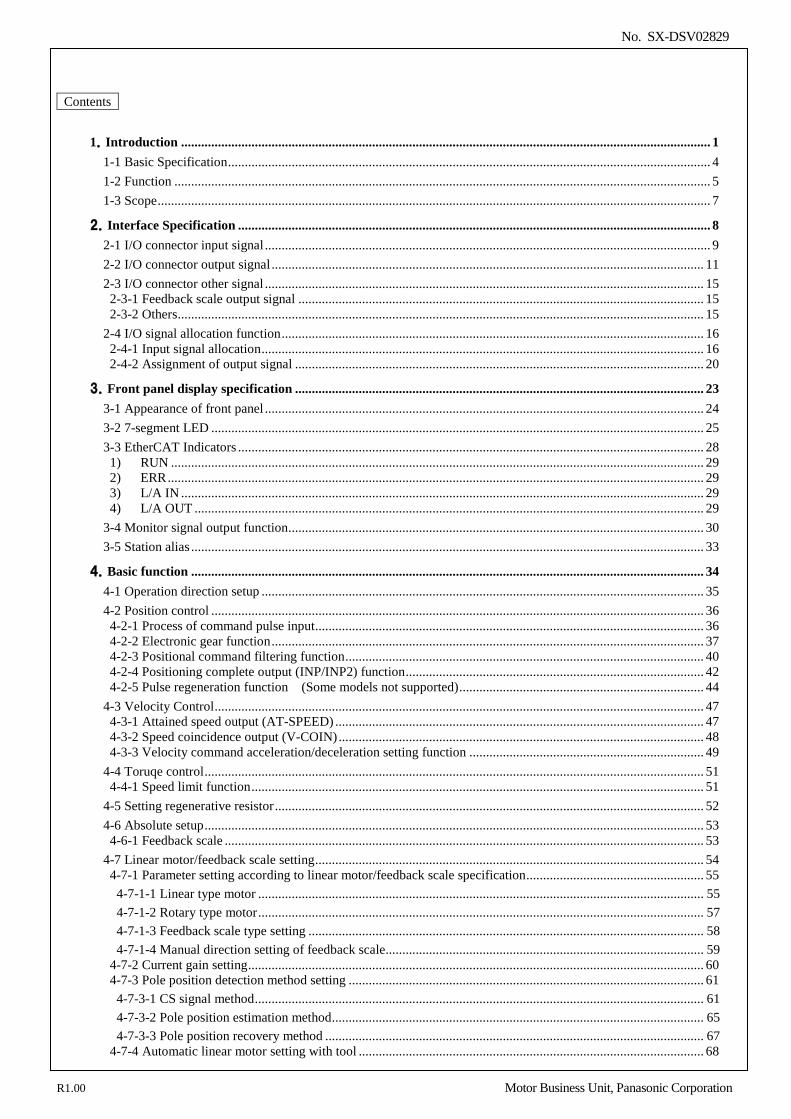
Contents
1.Introduction .............................................................................................................................................................. 1 1-1 Basic Specification ................................................................................................................................................ 4 1-2 Function ................................................................................................................................................................ 5 1-3 Scope ..................................................................................................................................................................... 7
2.Interface Specification ............................................................................................................................................. 8 2-1 I/O connector input signal ..................................................................................................................................... 9 2-2 I/O connector output signal ................................................................................................................................. 11 2-3 I/O connector other signal ................................................................................................................................... 15 2-3-1 Feedback scale output signal ......................................................................................................................... 15 2-3-2 Others ............................................................................................................................................................. 15
2-4 I/O signal allocation function .............................................................................................................................. 16 2-4-1 Input signal allocation .................................................................................................................................... 16 2-4-2 Assignment of output signal .......................................................................................................................... 20
3.Front panel display specification .......................................................................................................................... 23 3-1 Appearance of front panel ................................................................................................................................... 24 3-2 7-segment LED ................................................................................................................................................... 25 3-3 EtherCAT Indicators ........................................................................................................................................... 28 1) RUN ............................................................................................................................................................... 29 2) ERR ................................................................................................................................................................ 29 3) L/A IN ............................................................................................................................................................ 29 4) L/A OUT ........................................................................................................................................................ 29
3-4 Monitor signal output function ............................................................................................................................ 30 3-5 Station alias ......................................................................................................................................................... 33
4.Basic function ......................................................................................................................................................... 34 4-1 Operation direction setup .................................................................................................................................... 35 4-2 Position control ................................................................................................................................................... 36 4-2-1 Process of command pulse input .................................................................................................................... 36 4-2-2 Electronic gear function ................................................................................................................................. 37 4-2-3 Positional command filtering function ........................................................................................................... 40 4-2-4 Positioning complete output (INP/INP2) function ......................................................................................... 42 4-2-5 Pulse regeneration function (Some models not supported) ......................................................................... 44
4-3 Velocity Control .................................................................................................................................................. 47 4-3-1 Attained speed output (AT-SPEED) .............................................................................................................. 47 4-3-2 Speed coincidence output (V-COIN) ............................................................................................................. 48 4-3-3 Velocity command acceleration/deceleration setting function ...................................................................... 49
4-4 Toruqe control ..................................................................................................................................................... 51 4-4-1 Speed limit function ....................................................................................................................................... 51
4-5 Setting regenerative resistor ................................................................................................................................ 52 4-6 Absolute setup ..................................................................................................................................................... 53 4-6-1 Feedback scale ............................................................................................................................................... 53
4-7 Linear motor/feedback scale setting .................................................................................................................... 54 4-7-1 Parameter setting according to linear motor/feedback scale specification ..................................................... 55
4-7-1-1 Linear type motor ..................................................................................................................................... 55 4-7-1-2 Rotary type motor ..................................................................................................................................... 57 4-7-1-3 Feedback scale type setting ...................................................................................................................... 58 4-7-1-4 Manual direction setting of feedback scale............................................................................................... 59
4-7-2 Current gain setting ........................................................................................................................................ 60 4-7-3 Pole position detection method setting .......................................................................................................... 61
4-7-3-1 CS signal method ...................................................................................................................................... 61 4-7-3-2 Pole position estimation method ............................................................................................................... 65 4-7-3-3 Pole position recovery method ................................................................................................................. 67
4-7-4 Automatic linear motor setting with tool ....................................................................................................... 68
R1.00 Motor Business Unit, Panasonic Corporation
No. SX-DSV02829
5.Gain tuning/vibration suppressing function ........................................................................................................ 71 5-1 Automatic adjusting function .............................................................................................................................. 72 5-1-1 Real-Time Auto Tuning ................................................................................................................................. 73 5-1-2 Adaptive filter ................................................................................................................................................ 81 5-1-3 Real-time Auto Tuning (2 Degrees of Freedom Control Mode Standard type) .......................................... 84
5-2 Manual adjusting function................................................................................................................................... 92 5-2-1 Block diagram of position control mode ........................................................................................................ 93 5-2-2 Block diagram of velocity control mode ........................................................................................................ 94 5-2-3 Block diagram of torque control mode .......................................................................................................... 95 5-2-4 Gain Switching Function ............................................................................................................................... 96 5-2-5 Notch filter ................................................................................................................................................... 102 5-2-6 Damping Control ......................................................................................................................................... 104 5-2-7 Feed forward function .................................................................................................................................. 108 5-2-8 Instantaneous Velocity Observer function ................................................................................................... 110 5-2-9 Disturbance observer function ..................................................................................................................... 112 5-2-10 3rd gain switching function ....................................................................................................................... 114 5-2-11 Friction torque compensation .................................................................................................................... 115 5-2-12 2-stage torque filter .................................................................................................................................... 117 5-2-13 Mode of 2 degrees of freedom control (Standerd type) ............................................................................. 118 5-2-14 Model type damping filter ......................................................................................................................... 121 5-2-15 Viscous friction compensating gain / Model type damping filter application parameter switching function.................................................................................................................................................................. 125
6.Application ............................................................................................................................................................ 127 6-1 Torque limit switching function ........................................................................................................................ 128 6-2 Motor working range setup function ................................................................................................................. 129 6-3 Deceleration stop sequence ............................................................................................................................... 131 6-3-1 Sequence upon inputting of over-travel inhibition (POT, NOT) (under review) ......................................... 131 6-3-2 Sequence at Servo-Off ................................................................................................................................. 133 6-3-3 Sequence at main power OFF ...................................................................................................................... 134 6-3-4 Sequence at alarm ........................................................................................................................................ 136 6-3-5 Emergency stop upon occurrence of alarm .................................................................................................. 138
6-4 Torque saturation protection function ............................................................................................................... 140 7.Protective function/Warning function ................................................................................................................ 141
7-1 List of protective function ................................................................................................................................. 142 7-2 Details of Protective function ............................................................................................................................ 145 7-3 Warning function .............................................................................................................................................. 159 7-4 Setup of gain pre-adjustment protection ........................................................................................................... 162
8.Safety function ...................................................................................................................................................... 164 8-1 Outline description of safe torque off (STO) .................................................................................................... 165 8-2 Specifications of Input & output signals ........................................................................................................... 166 8-2-1 Safety input/ signal ...................................................................................................................................... 166 8-2-2 External device monitor (EDM) output signal ............................................................................................. 167 8-2-3 Internal signal circuit block diagram ........................................................................................................... 167
8-3 Detailed functional description ......................................................................................................................... 168 8-3-1 Operating timing for safety status ................................................................................................................ 168 8-3-2 Return timing from safety state .................................................................................................................... 169
8-4 Example of connection ...................................................................................................................................... 170 8-4-1 Example of connection to safety switch ...................................................................................................... 170 8-4-2 Example of connection to safety sensor ....................................................................................................... 170 8-4-3 Example of connection to safety controller ................................................................................................. 171 8-4-4 Example of connection when using multiple axes ....................................................................................... 172
8-5 Safety precautions ............................................................................................................................................. 173
R1.00 Motor Business Unit, Panasonic Corporation
No. SX-DSV02829
9.Other ..................................................................................................................................................................... 175 9-1 List of parameters .............................................................................................................................................. 176 9-2 Timing Chart ..................................................................................................................................................... 192 9-2-1 Servo-on signal accept timing on power-up: When magnet pole position estimation is valid (Pr 9.20 = 2) ................ 192 9-2-2 Servo-on signal accept timing on power-up: When magnet pole position estimation is invalid (Pr 9.20 = 0, 1, 3) ...... 194 9-2-3 Servo-ON/OFF action while the motor is at stall (servo-lock) .................................................................... 196 9-2-4 Servo-ON/OFF action while the motor is in motion .................................................................................... 197 9-2-5 When an error (alarm) has occurred (at Servo-ON command) (DB deceleration,Free run deceleration movement) ............................................................................................................................................................. 198 9-2-6 When an error (alarm) has occurred (at Servo-ON command) (Emergency stop movement) ..................... 199 9-2-7 When an alarm has been cleared (at Servo-ON command) ......................................................................... 200
R1.00 Motor Business Unit, Panasonic Corporation
No. SX-DSV02829 -1-
1.Introduction
1-1 Basic Specification ................................................................................................................................................ 4 1-2 Function ................................................................................................................................................................. 5 1-3 Scope ..................................................................................................................................................................... 7
1
R1.00 Motor Business Unit, Panasonic Corporation
No. SX-DSV02829 -2-
This document describes the functions of the linear motor supported servo amplifier MINAS-A5BL series (read MINAS-A5B as MINAS-A5BL, below) equipped with the EtherCAT communication function.
<Software version> This technical reference applies to the servo drivers compatible with software of the following version: Version 1: Ver8.00 or later Version 2: Ver8.00 or later
Version 3: Ver1.00 or later * Check the software versions 1 and 2 by 3744h (Reference to section 5-2 of EtherCAT communication
specification) or setup support software PANATERM. * Check the software version 3 by 100Ah(Reference to section 5-2 of EtherCAT communication specification).
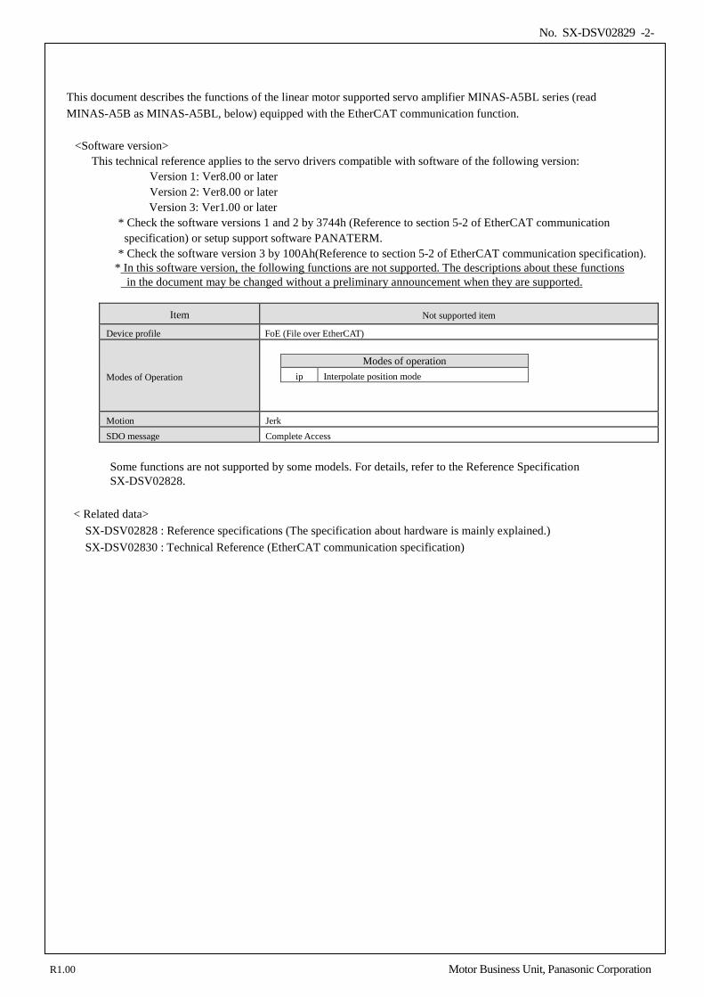
* In this software version, the following functions are not supported. The descriptions about these functions in the document may be changed without a preliminary announcement when they are supported.
Item Not supported item
Device profile FoE (File over EtherCAT)
Modes of Operation
Modes of operation
ip Interpolate position mode
Motion Jerk SDO message Complete Access
Some functions are not supported by some models. For details, refer to the Reference Specification SX-DSV02828.
< Related data>
SX-DSV02828 : Reference specifications (The specification about hardware is mainly explained.) SX-DSV02830 : Technical Reference (EtherCAT communication specification)
R1.00 Motor Business Unit, Panasonic Corporation
No. SX-DSV02829 -3-
<IMPORTANT> • All rights reserved. No part of this publication may be reproduced or transmitted in any form without prior
permission. • Motor Business Division, Appliances Company, Panasonic Corp. reserves the right to make modifications and
improvements to its products and/or documentation, including specifications and software, without prior notice. • In general, these specifications adopt the names/units based on the rotary type.
The table below lists the correlation with linear type, so read the difference as such. However, the signal symbols, etc. (TLC and Torque_Limited, for example) are for rotary type, read them as a linear type.
Linear type Rotary type Mass Inertia
Thrust Torque mm/s r/min
EtherCAT® is registered trademark and patented technology, licensed by Beckhoff Automation GmbH, Germany.
R1.00 Motor Business Unit, Panasonic Corporation
No. SX-DSV02829 -4-
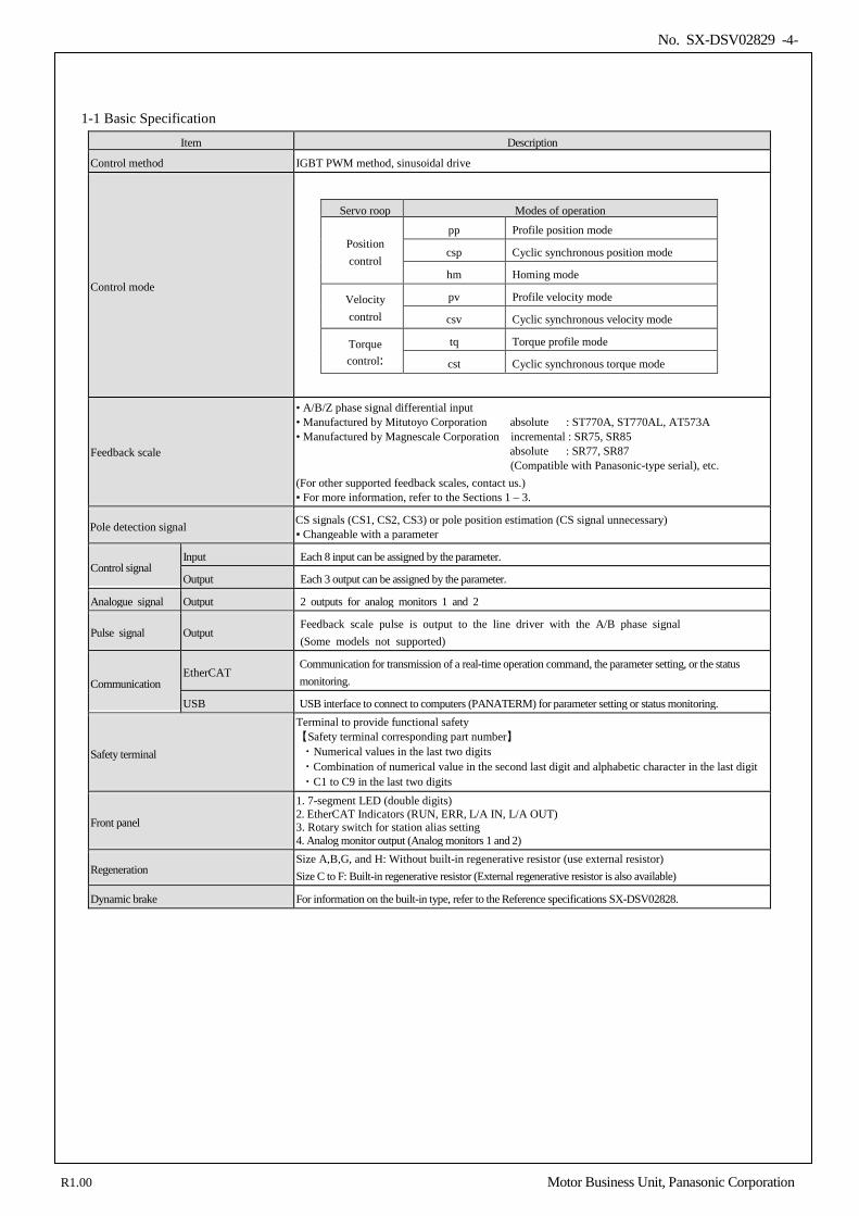
1-1 Basic Specification Item Description
Control method IGBT PWM method, sinusoidal drive
Control mode
Servo roop Modes of operation
Position control
pp Profile position mode
csp Cyclic synchronous position mode
hm Homing mode
Velocity control
pv Profile velocity mode
csv Cyclic synchronous velocity mode
Torque control:
tq Torque profile mode
cst Cyclic synchronous torque mode
Feedback scale
• A/B/Z phase signal differential input • Manufactured by Mitutoyo Corporation absolute : ST770A, ST770AL, AT573A • Manufactured by Magnescale Corporation incremental : SR75, SR85 absolute : SR77, SR87
(Compatible with Panasonic-type serial), etc. (For other supported feedback scales, contact us.) For more information, refer to the Sections 1 – 3.
Pole detection signal CS signals (CS1, CS2, CS3) or pole position estimation (CS signal unnecessary) Changeable with a parameter
Control signal Input Each 8 input can be assigned by the parameter.
Output Each 3 output can be assigned by the parameter.
Analogue signal Output 2 outputs for analog monitors 1 and 2
Pulse signal Output Feedback scale pulse is output to the line driver with the A/B phase signal (Some models not supported)
Communication EtherCAT
Communication for transmission of a real-time operation command, the parameter setting, or the status monitoring.
USB USB interface to connect to computers (PANATERM) for parameter setting or status monitoring.
Safety terminal
Terminal to provide functional safety 【Safety terminal corresponding part number】 ・Numerical values in the last two digits ・Combination of numerical value in the second last digit and alphabetic character in the last digit ・C1 to C9 in the last two digits
Front panel
1. 7-segment LED (double digits) 2. EtherCAT Indicators (RUN, ERR, L/A IN, L/A OUT) 3. Rotary switch for station alias setting 4. Analog monitor output (Analog monitors 1 and 2)
Regeneration Size A,B,G, and H: Without built-in regenerative resistor (use external resistor) Size C to F: Built-in regenerative resistor (External regenerative resistor is also available)
Dynamic brake For information on the built-in type, refer to the Reference specifications SX-DSV02828.
R1.00 Motor Business Unit, Panasonic Corporation
No. SX-DSV02829 -5-
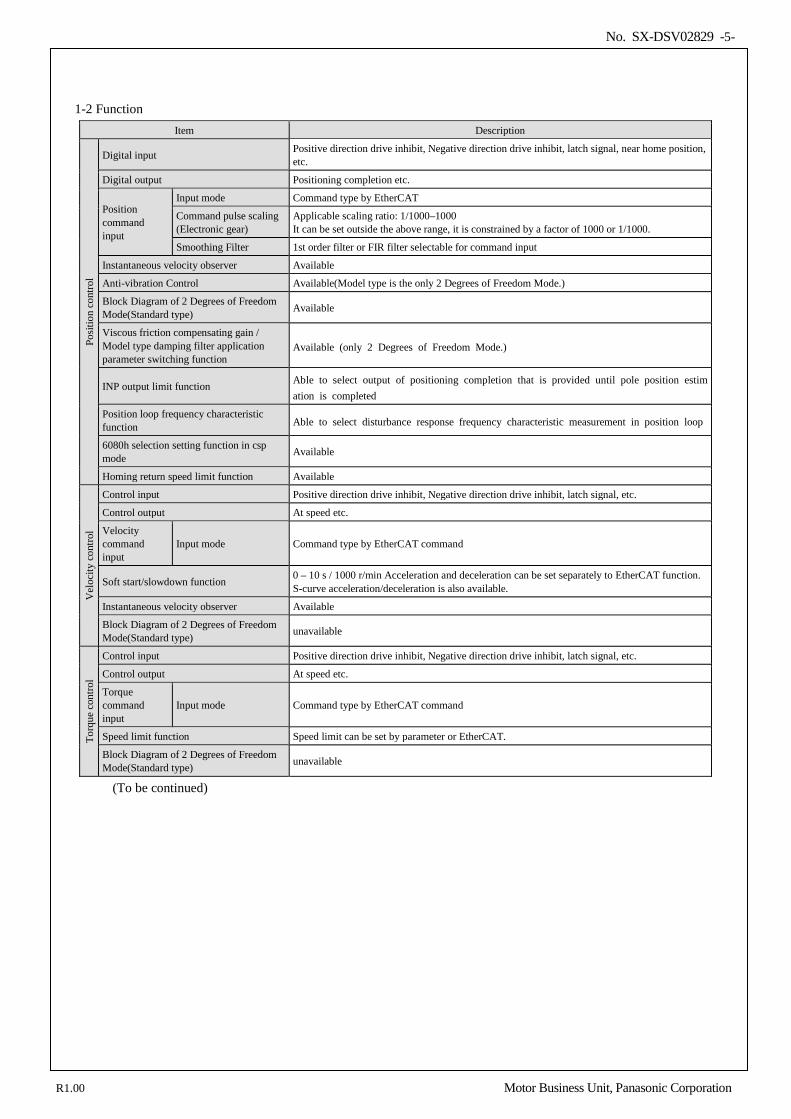
1-2 Function Item Description
Posit
ion
cont
rol
Digital input Positive direction drive inhibit, Negative direction drive inhibit, latch signal, near home position, etc.
Digital output Positioning completion etc.
Position command input
Input mode Command type by EtherCAT
Command pulse scaling (Electronic gear)
Applicable scaling ratio: 1/1000–1000 It can be set outside the above range, it is constrained by a factor of 1000 or 1/1000.
Smoothing Filter 1st order filter or FIR filter selectable for command input
Instantaneous velocity observer Available
Anti-vibration Control Available(Model type is the only 2 Degrees of Freedom Mode.)
Block Diagram of 2 Degrees of Freedom Mode(Standard type) Available
Viscous friction compensating gain / Model type damping filter application parameter switching function
Available (only 2 Degrees of Freedom Mode.)
INP output limit function Able to select output of positioning completion that is provided until pole position estimation is completed
Position loop frequency characteristic function Able to select disturbance response frequency characteristic measurement in position loop
6080h selection setting function in csp mode Available
Homing return speed limit function Available
Vel
ocity
con
trol
Control input Positive direction drive inhibit, Negative direction drive inhibit, latch signal, etc.
Control output At speed etc.
Velocity command input
Input mode Command type by EtherCAT command
Soft start/slowdown function 0 – 10 s / 1000 r/min Acceleration and deceleration can be set separately to EtherCAT function. S-curve acceleration/deceleration is also available.
Instantaneous velocity observer Available
Block Diagram of 2 Degrees of Freedom Mode(Standard type) unavailable
Torq
ue c
ontro
l
Control input Positive direction drive inhibit, Negative direction drive inhibit, latch signal, etc.
Control output At speed etc.
Torque command input
Input mode Command type by EtherCAT command
Speed limit function Speed limit can be set by parameter or EtherCAT.
Block Diagram of 2 Degrees of Freedom Mode(Standard type) unavailable
(To be continued)
R1.00 Motor Business Unit, Panasonic Corporation
No. SX-DSV02829 -6-
Item Description
Com
mon
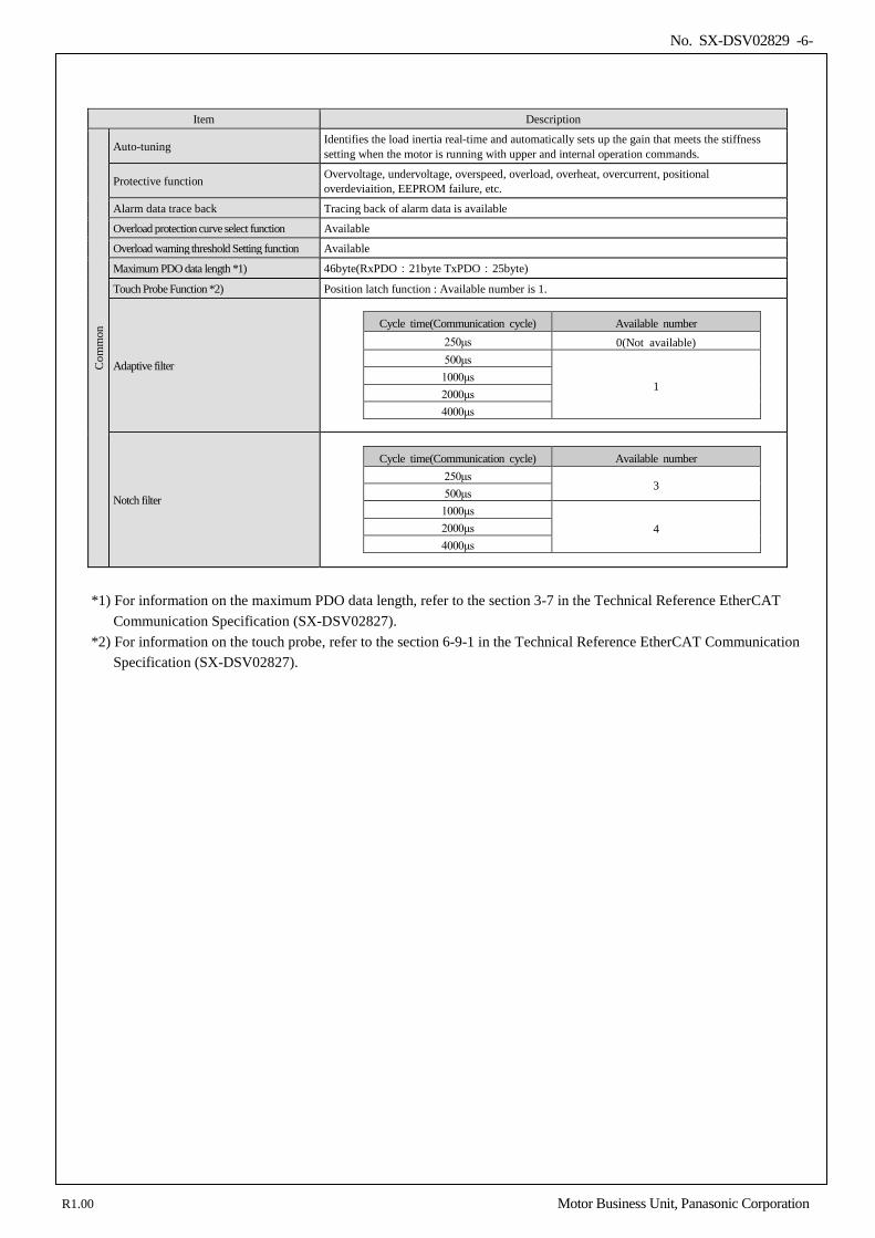
Auto-tuning Identifies the load inertia real-time and automatically sets up the gain that meets the stiffness setting when the motor is running with upper and internal operation commands.
Protective function Overvoltage, undervoltage, overspeed, overload, overheat, overcurrent, positional overdeviaition, EEPROM failure, etc.
Alarm data trace back Tracing back of alarm data is available
Overload protection curve select function Available
Overload warning threshold Setting function Available
Maximum PDO data length *1) 46byte(RxPDO:21byte TxPDO:25byte)
Touch Probe Function *2) Position latch function : Available number is 1.
Adaptive filter
Cycle time(Communication cycle) Available number 250μs 0(Not available) 500μs
1 1000μs 2000μs 4000μs
Notch filter
Cycle time(Communication cycle) Available number 250μs
3 500μs 1000μs
4 2000μs 4000μs
*1) For information on the maximum PDO data length, refer to the section 3-7 in the Technical Reference EtherCAT
Communication Specification (SX-DSV02827). *2) For information on the touch probe, refer to the section 6-9-1 in the Technical Reference EtherCAT Communication
Specification (SX-DSV02827).
R1.00 Motor Business Unit, Panasonic Corporation
No. SX-DSV02829 -7-
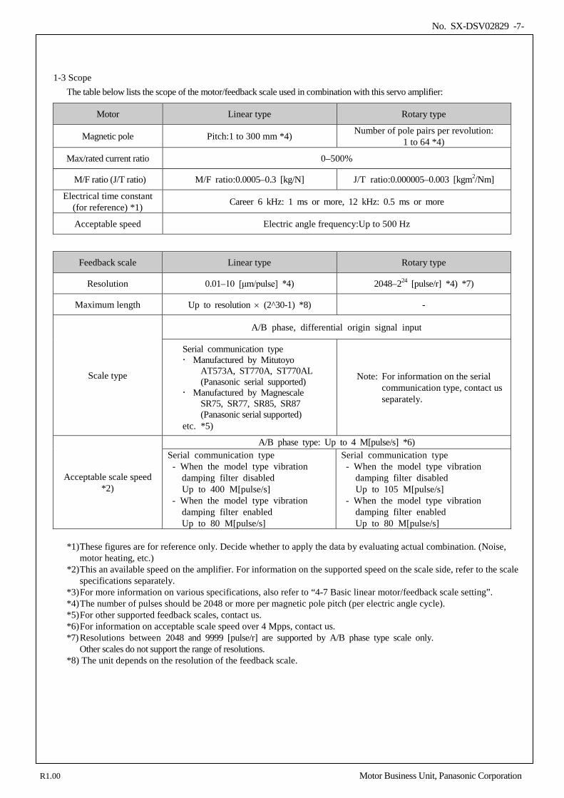
1-3 Scope The table below lists the scope of the motor/feedback scale used in combination with this servo amplifier:
*1) These figures are for reference only. Decide whether to apply the data by evaluating actual combination. (Noise,
motor heating, etc.) *2) This an available speed on the amplifier. For information on the supported speed on the scale side, refer to the scale
specifications separately. *3) For more information on various specifications, also refer to “4-7 Basic linear motor/feedback scale setting”. *4) The number of pulses should be 2048 or more per magnetic pole pitch (per electric angle cycle). *5) For other supported feedback scales, contact us. *6) For information on acceptable scale speed over 4 Mpps, contact us. *7) Resolutions between 2048 and 9999 [pulse/r] are supported by A/B phase type scale only. Other scales do not support the range of resolutions. *8) The unit depends on the resolution of the feedback scale.
Motor Linear type Rotary type
Magnetic pole Pitch:1 to 300 mm *4) Number of pole pairs per revolution: 1 to 64 *4)
Max/rated current ratio 0–500%
M/F ratio (J/T ratio) M/F ratio:0.0005–0.3 [kg/N] J/T ratio:0.000005–0.003 [kgm2/Nm]
Electrical time constant (for reference) *1) Career 6 kHz: 1 ms or more, 12 kHz: 0.5 ms or more
Acceptable speed Electric angle frequency:Up to 500 Hz
Feedback scale Linear type Rotary type
Resolution 0.01–10 [μm/pulse] *4) 2048–224 [pulse/r] *4) *7)
Maximum length Up to resolution × (2^30-1) *8) -
Scale type
A/B phase, differential origin signal input
Serial communication type Manufactured by Mitutoyo
AT573A, ST770A, ST770AL (Panasonic serial supported)
Manufactured by Magnescale SR75, SR77, SR85, SR87 (Panasonic serial supported)
etc. *5)
Note: For information on the serial communication type, contact us separately.
Acceptable scale speed *2)
A/B phase type: Up to 4 M[pulse/s] *6) Serial communication type - When the model type vibration
damping filter disabled Up to 400 M[pulse/s] - When the model type vibration
damping filter enabled Up to 80 M[pulse/s]
Serial communication type - When the model type vibration
damping filter disabled Up to 105 M[pulse/s] - When the model type vibration
damping filter enabled Up to 80 M[pulse/s]
R1.00 Motor Business Unit, Panasonic Corporation
No. SX-DSV02829 -8-
2.Interface Specification
2-1 I/O connector input signal ..................................................................................................................................... 9 2-2 I/O connector output signal ................................................................................................................................. 11 2-3 I/O connector other signal ................................................................................................................................... 15 2-3-1 Feedback scale output signal .......................................................................................................................... 15 2-3-2 Others ............................................................................................................................................................. 15
2-4 I/O signal allocation function .............................................................................................................................. 16 2-4-1 Input signal allocation .................................................................................................................................... 16 2-4-2 Assignment of output signal........................................................................................................................... 20
2
R1.00 Motor Business Unit, Panasonic Corporation
No. SX-DSV02829 -9-
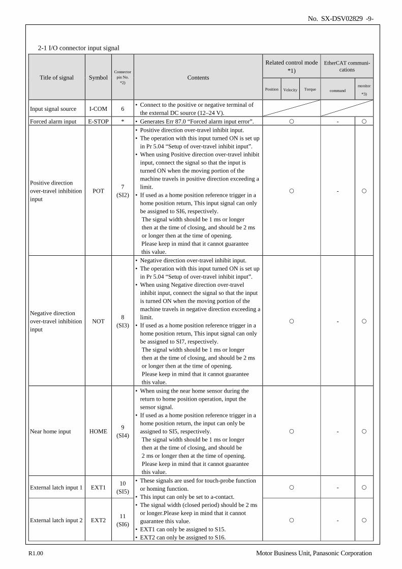
2-1 I/O connector input signal
Title of signal Symbol Connector
pin No. *2)
Contents
Related control mode *1)
EtherCAT communi- cations
Position Velocity Torque command monitor
*3)
Input signal source I-COM 6 • Connect to the positive or negative terminal of
the external DC source (12–24 V).
Forced alarm input E-STOP * • Generates Err 87.0 “Forced alarm input error”. -
Positive direction over-travel inhibition input
POT 7
(SI2)
• Positive direction over-travel inhibit input. • The operation with this input turned ON is set up
in Pr 5.04 “Setup of over-travel inhibit input”. • When using Positive direction over-travel inhibit
input, connect the signal so that the input is turned ON when the moving portion of the machine travels in positive direction exceeding a limit.
• If used as a home position reference trigger in a home position return, This input signal can only be assigned to SI6, respectively. The signal width should be 1 ms or longer then at the time of closing, and should be 2 ms or longer then at the time of opening. Please keep in mind that it cannot guarantee this value.
-
Negative direction over-travel inhibition input
NOT 8
(SI3)
• Negative direction over-travel inhibit input. • The operation with this input turned ON is set up
in Pr 5.04 “Setup of over-travel inhibit input”. • When using Negative direction over-travel
inhibit input, connect the signal so that the input is turned ON when the moving portion of the machine travels in negative direction exceeding a limit.
• If used as a home position reference trigger in a home position return, This input signal can only be assigned to SI7, respectively. The signal width should be 1 ms or longer then at the time of closing, and should be 2 ms or longer then at the time of opening. Please keep in mind that it cannot guarantee this value.
-
Near home input HOME 9
(SI4)
• When using the near home sensor during the return to home position operation, input the sensor signal.
• If used as a home position reference trigger in a home position return, the input can only be assigned to SI5, respectively. The signal width should be 1 ms or longer then at the time of closing, and should be 2 ms or longer then at the time of opening. Please keep in mind that it cannot guarantee this value.
-
External latch input 1 EXT1 10
(SI5)
• These signals are used for touch-probe function or homing function.
• This input can only be set to a-contact. • The signal width (closed period) should be 2 ms
or longer.Please keep in mind that it cannot guarantee this value.
• EXT1 can only be assigned to S15. • EXT2 can only be assigned to S16.
-
External latch input 2 EXT2 11
(SI6) -
R1.00 Motor Business Unit, Panasonic Corporation
No. SX-DSV02829 -10-
Title of signal Symbol Connector
pin No. *2)
Contents
Related control mode *1)
EtherCAT communi- cations
Position Velocity Torque command monitor
*3)
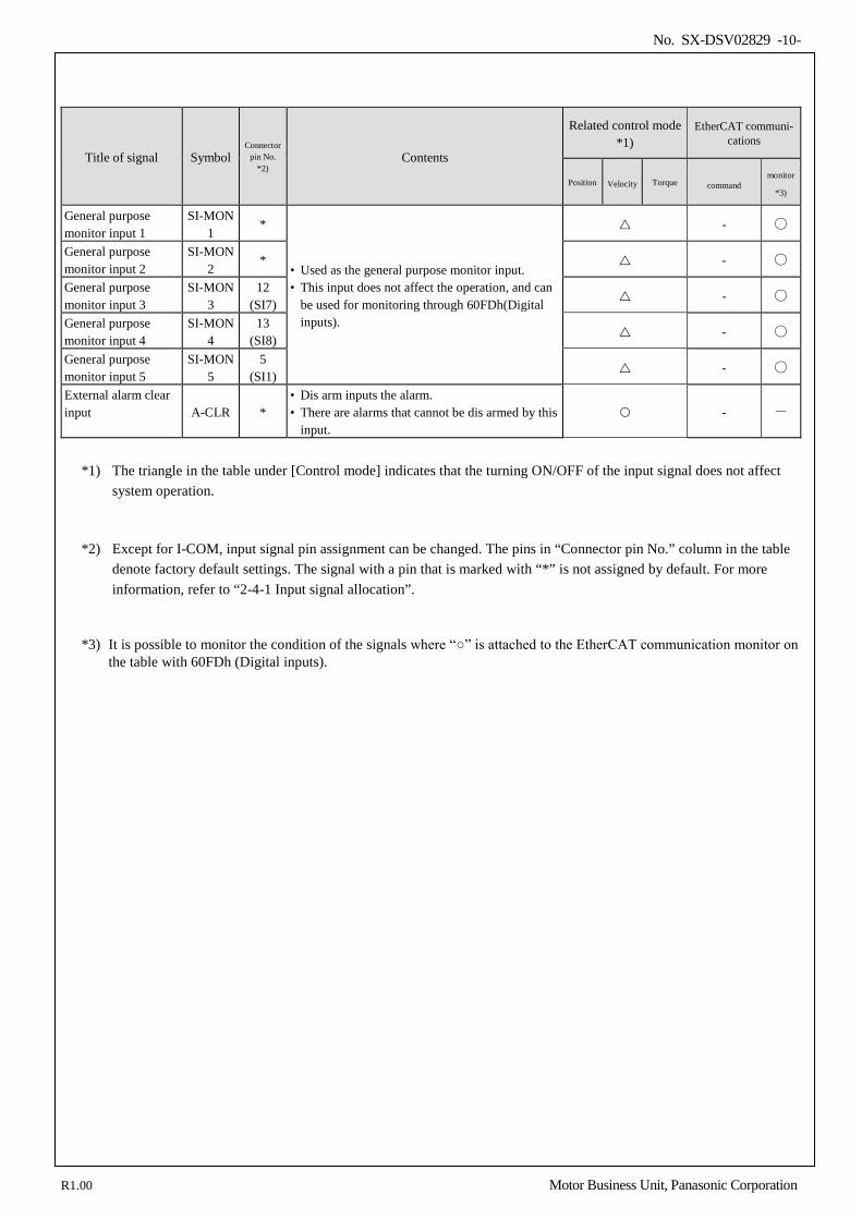
General purpose monitor input 1
SI-MON1
*
• Used as the general purpose monitor input. • This input does not affect the operation, and can
be used for monitoring through 60FDh(Digital inputs).
-
General purpose monitor input 2
SI-MON2
* -
General purpose monitor input 3
SI-MON3
12 (SI7) -
General purpose monitor input 4
SI-MON4
13 (SI8) -
General purpose monitor input 5
SI-MON5
5 (SI1) -
External alarm clear input A-CLR *
• Dis arm inputs the alarm. • There are alarms that cannot be dis armed by this
input. - -
*1) The triangle in the table under [Control mode] indicates that the turning ON/OFF of the input signal does not affect
system operation.
*2) Except for I-COM, input signal pin assignment can be changed. The pins in “Connector pin No.” column in the table denote factory default settings. The signal with a pin that is marked with “*” is not assigned by default. For more information, refer to “2-4-1 Input signal allocation”.
*3) It is possible to monitor the condition of the signals where “” is attached to the EtherCAT communication monitor on the table with 60FDh (Digital inputs).
R1.00 Motor Business Unit, Panasonic Corporation
No. SX-DSV02829 -11-
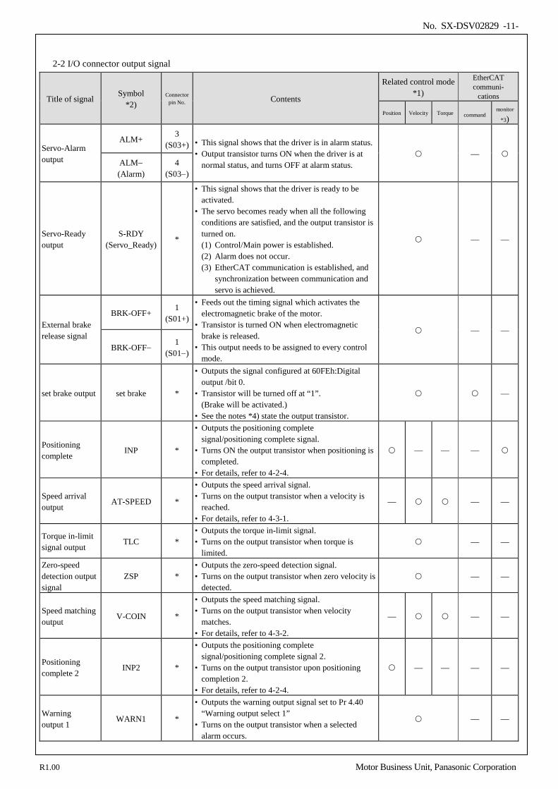
2-2 I/O connector output signal
Title of signal Symbol
*2) Connector
pin No. Contents
Related control mode *1)
EtherCAT communi-
cations
Position Velocity Torque command monitor
*3)
Servo-Alarm output
ALM+ 3
(S03+) • This signal shows that the driver is in alarm status. • Output transistor turns ON when the driver is at
normal status, and turns OFF at alarm status. —
ALM− (Alarm)
4 (S03−)
Servo-Ready output
S-RDY (Servo_Ready)
*
• This signal shows that the driver is ready to be activated.
• The servo becomes ready when all the following conditions are satisfied, and the output transistor is turned on. (1) Control/Main power is established. (2) Alarm does not occur. (3) EtherCAT communication is established, and
synchronization between communication and servo is achieved.
— —
External brake release signal
BRK-OFF+ 1
(S01+)
• Feeds out the timing signal which activates the electromagnetic brake of the motor.
• Transistor is turned ON when electromagnetic brake is released.
• This output needs to be assigned to every control mode.
— —
BRK-OFF− 1
(S01−)
set brake output set brake *
• Outputs the signal configured at 60FEh:Digital output /bit 0.
• Transistor will be turned off at “1”. (Brake will be activated.)
• See the notes *4) state the output transistor.
—
Positioning complete
INP *
• Outputs the positioning complete signal/positioning complete signal.
• Turns ON the output transistor when positioning is completed.
• For details, refer to 4-2-4.
— — —
Speed arrival output
AT-SPEED *
• Outputs the speed arrival signal. • Turns on the output transistor when a velocity is
reached. • For details, refer to 4-3-1.
— — —
Torque in-limit signal output
TLC * • Outputs the torque in-limit signal. • Turns on the output transistor when torque is
limited. — —
Zero-speed detection output signal
ZSP * • Outputs the zero-speed detection signal. • Turns on the output transistor when zero velocity is
detected. — —
Speed matching output
V-COIN *
• Outputs the speed matching signal. • Turns on the output transistor when velocity
matches. • For details, refer to 4-3-2.
— — —
Positioning complete 2
INP2 *
• Outputs the positioning complete signal/positioning complete signal 2.
• Turns on the output transistor upon positioning completion 2.
• For details, refer to 4-2-4.
— — — —
Warning output 1
WARN1 *
• Outputs the warning output signal set to Pr 4.40 “Warning output select 1”
• Turns on the output transistor when a selected alarm occurs.
— —
R1.00 Motor Business Unit, Panasonic Corporation
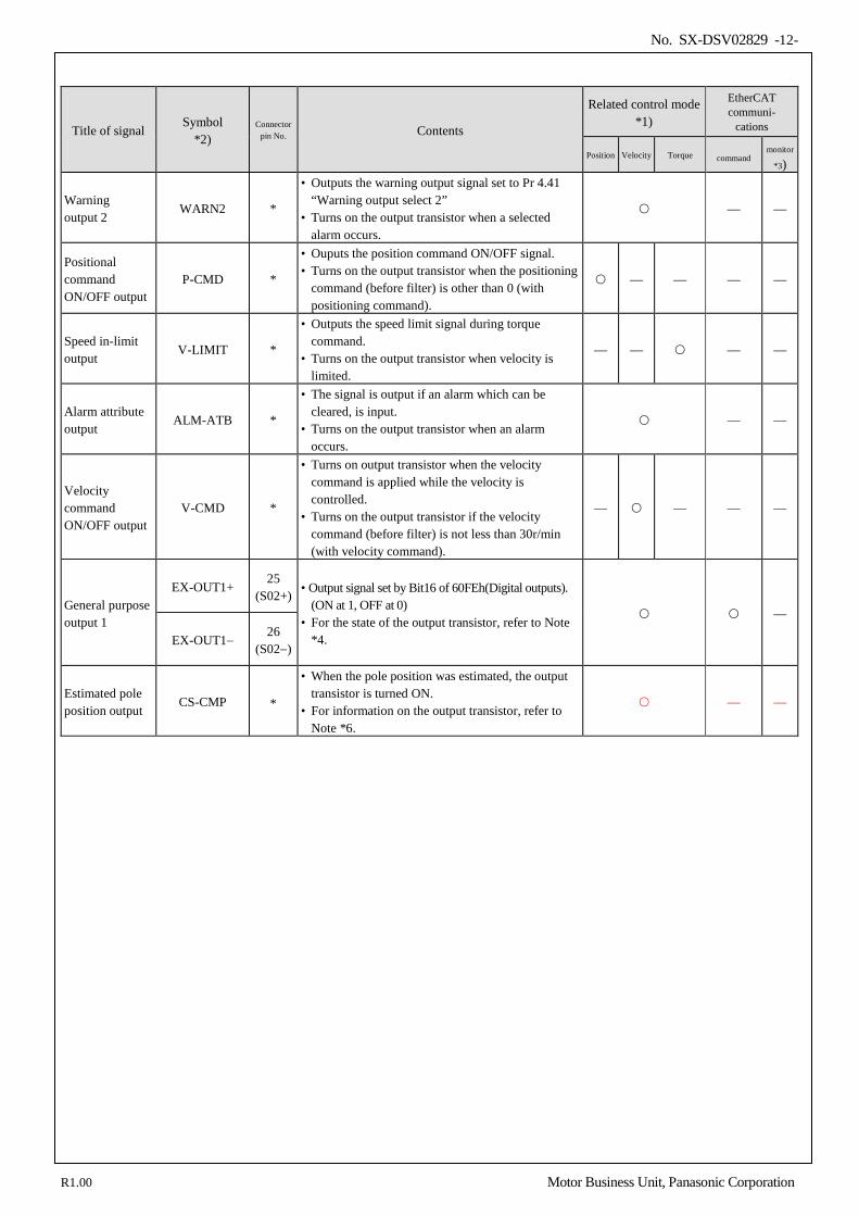
No. SX-DSV02829 -12-
Title of signal Symbol
*2) Connector
pin No. Contents
Related control mode *1)
EtherCAT communi-
cations
Position Velocity Torque command monitor
*3)
Warning output 2
WARN2 *
• Outputs the warning output signal set to Pr 4.41 “Warning output select 2”
• Turns on the output transistor when a selected alarm occurs.
— —
Positional command ON/OFF output
P-CMD *
• Ouputs the position command ON/OFF signal. • Turns on the output transistor when the positioning
command (before filter) is other than 0 (with positioning command).
— — — —
Speed in-limit output
V-LIMIT *
• Outputs the speed limit signal during torque command.
• Turns on the output transistor when velocity is limited.
— — — —
Alarm attribute output
ALM-ATB *
• The signal is output if an alarm which can be cleared, is input.
• Turns on the output transistor when an alarm occurs.
— —
Velocity command ON/OFF output
V-CMD *
• Turns on output transistor when the velocity command is applied while the velocity is controlled.
• Turns on the output transistor if the velocity command (before filter) is not less than 30r/min (with velocity command).
— — — —
General purpose output 1
EX-OUT1+ 25
(S02+) • Output signal set by Bit16 of 60FEh(Digital outputs). (ON at 1, OFF at 0)
• For the state of the output transistor, refer to Note *4.
—
EX-OUT1− 26
(S02−)
Estimated pole position output
CS-CMP *
• When the pole position was estimated, the output transistor is turned ON.
• For information on the output transistor, refer to Note *6.
— —
R1.00 Motor Business Unit, Panasonic Corporation
No. SX-DSV02829 -13-
*1) For the signal with “-” sign in the “Related control mode” column, the output transistor is always turned off in
that control mode. *2) Output pin assignment can be changed. The pins in “Connector pin No.” column in the table denote factory
default settings. The signal with a pin that is marked with “*” is not assigned by default. For more information, refer to “2-4-2 Assignment of output signal”.
*3) It is possible to monitor the condition of the signals where “” is attached to the EtherCAT communication
monitor on the table with 60FDh (Digital inputs).
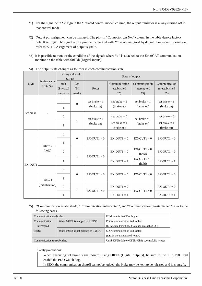
*4) The output state changes as follows in each communication state:
Sign Setting value
of 3724h
Setting value of 60FEh
State of output
01h (Physical outputs)
02h (Bit
mask) Reset
Communication established
*5)
Communication intercepterd
*5)
Communication re-established
*5)
set brake -
0 0
set brake = 1 (brake on)
set brake = 1 (brake on)
set brake = 1 (brake on)
set brake = 1 (brake on) 1
0 1
set brake = 1 (brake on)
set brake = 0 set brake = 1
(brake on)
set brake = 0
1 set brake = 1
(brake on) set brake = 1
(brake on)
EX-OUT1
bit0 = 0 (hold)
0 0 EX-OUT1 = 0 EX-OUT1 = 0 EX-OUT1 = 0 EX-OUT1 = 0
1
0 1 EX-OUT1 = 0
EX-OUT1 = 0 EX-OUT1 = 0
(hold) EX-OUT1 = 0
1 EX-OUT1 = 1 EX-OUT1 = 1
(hold) EX-OUT1 = 1
bit0 = 1 (initialization)
0 0 EX-OUT1 = 0 EX-OUT1 = 0 EX-OUT1 = 0 EX-OUT1 = 0
1
0 1 EX-OUT1 = 0
EX-OUT1 = 0 EX-OUT1 = 0
EX-OUT1 = 0
1 EX-OUT1 = 1 EX-OUT1 = 1
*5) “Communication established”, “Communication intercepted”, and “Communication re-established” refer to the
following cases. Communication established ESM state is PreOP or higher
Communication
intercepted
(Note)
When 60FEh is mapped to RxPDO PDO communication is disabled
(ESM state transitioned to other states than OP)
When 60FEh is not mapped to RxPDO SDO communication is disabled
(ESM state transitioned to Init)
Communication re-established Until 60FEh-01h or 60FEh-02h is successfully written
Safety precautions:
When executing set brake signal control using 60FEh (Digital outputs), be sure to use it in PDO and enable the PDO watch dog. In SDO, the communication shutoff cannot be judged, the brake may be kept to be released and it is unsafe.
R1.00 Motor Business Unit, Panasonic Corporation
No. SX-DSV02829 -14-
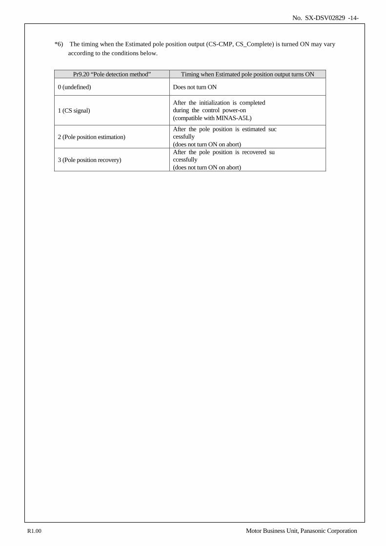
*6) The timing when the Estimated pole position output (CS-CMP, CS_Complete) is turned ON may vary
according to the conditions below.
Pr9.20 “Pole detection method” Timing when Estimated pole position output turns ON
0 (undefined) Does not turn ON
1 (CS signal) After the initialization is completed during the control power-on (compatible with MINAS-A5L)
2 (Pole position estimation) After the pole position is estimated suc cessfully (does not turn ON on abort)
3 (Pole position recovery) After the pole position is recovered su ccessfully (does not turn ON on abort)
R1.00 Motor Business Unit, Panasonic Corporation

No. SX-DSV02829 -15-
2-3 I/O connector other signal
2-3-1 Feedback scale output signal
Title of signal Symbol Connector pin No. Contents Control mode Control mode
Position Velocity Torque Commdnd monitor
A-phase output OA+ 17 • Feeds out the divided feedback scale signal or
external scale signal (A, B-phase) in differential. (equivalent to RS422)
• Ground for line driver of output circuit is connected to signal ground (GND) and is not insulated.
• Max. output frequency is 4 Mpps (after quadrupled)
- -
OA− 18
B-phase output
OB+ 20
OB− 19
Signal ground GND 16 • Signal ground
2-3-2 Others
Title of signal Symbol Connector pin No. Contents
Control mode EtherCAT communi-
cations
Position Velocity Torque command monitor
Frame ground FG shell • This output is connected to the ground terminal
inside of the driver.
To be used by the manufacturer.
— 14,15 21, 22 23, 24
• Keep these pins unconnected.
R1.00 Motor Business Unit, Panasonic Corporation
No. SX-DSV02829 -16-
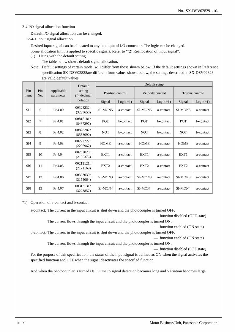
2-4 I/O signal allocation function
Default I/O signal allocation can be changed. 2-4-1 Input signal allocation
Desired input signal can be allocated to any input pin of I/O connector. The logic can be changed. Some allocation limit is applied to specific signals. Refer to “(2) Reallocation of input signal”. (1) Using with the default setting
The table below shows default signal allocation. Note: Default settings of certain model will differ from those shown below. If the default settings shown in Reference
specification SX-DSV02828are different from values shown below, the settings described in SX-DSV02828 are valid default values.
Pin name
Pin No.
Applicable parameter
Default setting
( ): decimal notation
Default setup
Position control Velocity control Torque control
Signal Logic *1) Signal Logic *1) Signal Logic *1)
SI1 5 Pr 4.00 00323232h (3289650)
SI-MON5 a-contact SI-MON5 a-contact SI-MON5 a-contact
SI2 7 Pr 4.01 00818181h (8487297)
POT b-contact POT b-contact POT b-contact
SI3 8 Pr 4.02 00828282h (8553090)
NOT b-contact NOT b-contact NOT b-contact
SI4 9 Pr 4.03 00222222h (2236962)
HOME a-contact HOME a-contact HOME a-contact
SI5 10 Pr 4.04 00202020h (2105376)
EXT1 a-contact EXT1 a-contact EXT1 a-contact
SI6 11 Pr 4.05 00212121h (2171169)
EXT2 a-contact EXT2 a-contact EXT2 a-contact
SI7 12 Pr 4.06 00303030h (3158064)
SI-MON3 a-contact SI-MON3 a-contact SI-MON3 a-contact
SI8 13 Pr 4.07 00313131h (3223857)
SI-MON4 a-contact SI-MON4 a-contact SI-MON4 a-contact
*1) Operation of a-contact and b-contact:
a-contact: The current in the input circuit is shut down and the photocoupler is turned OFF. — function disabled (OFF state) The current flows through the input circuit and the photocoupler is turned ON. — function enabled (ON state)
b-contact: The current in the input circuit is shut down and the photocoupler is turned OFF. — function enabled (ON state) The current flows through the input circuit and the photocoupler is turned ON. — function disabled (OFF state)
For the purpose of this specification, the status of the input signal is defined as ON when the signal activates the specified function and OFF when the signal deactivates the specified function. And when the photocoupler is turned OFF, time to signal detection becomes long and Variation becomes large.
R1.00 Motor Business Unit, Panasonic Corporation
No. SX-DSV02829 -17-
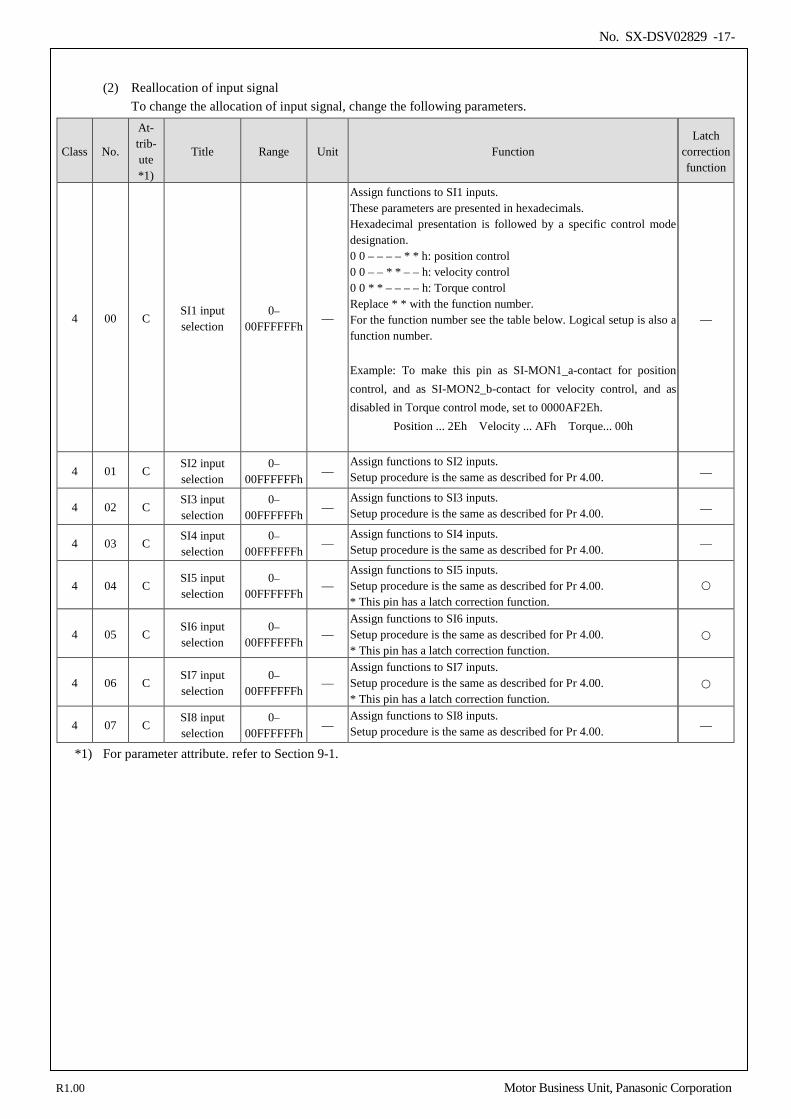
(2) Reallocation of input signal
To change the allocation of input signal, change the following parameters.
Class No.
At- trib- ute *1)
Title Range Unit Function Latch
correction function
4 00 C SI1 input selection
0– 00FFFFFFh
—
Assign functions to SI1 inputs. These parameters are presented in hexadecimals. Hexadecimal presentation is followed by a specific control mode designation. 0 0 – – – – * * h: position control 0 0 – – * * – – h: velocity control 0 0 * * – – – – h: Torque control Replace * * with the function number. For the function number see the table below. Logical setup is also a function number. Example: To make this pin as SI-MON1_a-contact for position control, and as SI-MON2_b-contact for velocity control, and as disabled in Torque control mode, set to 0000AF2Eh.
Position ... 2Eh Velocity ... AFh Torque... 00h
—
4 01 C SI2 input selection
0– 00FFFFFFh
— Assign functions to SI2 inputs. Setup procedure is the same as described for Pr 4.00. —
4 02 C SI3 input selection
0– 00FFFFFFh
— Assign functions to SI3 inputs. Setup procedure is the same as described for Pr 4.00. —
4 03 C SI4 input selection
0– 00FFFFFFh
— Assign functions to SI4 inputs. Setup procedure is the same as described for Pr 4.00. —
4 04 C SI5 input selection
0– 00FFFFFFh
— Assign functions to SI5 inputs. Setup procedure is the same as described for Pr 4.00. * This pin has a latch correction function.
4 05 C SI6 input selection
0– 00FFFFFFh
— Assign functions to SI6 inputs. Setup procedure is the same as described for Pr 4.00. * This pin has a latch correction function.
4 06 C SI7 input selection
0– 00FFFFFFh
— Assign functions to SI7 inputs. Setup procedure is the same as described for Pr 4.00. * This pin has a latch correction function.
4 07 C SI8 input selection
0– 00FFFFFFh
— Assign functions to SI8 inputs. Setup procedure is the same as described for Pr 4.00. —
*1) For parameter attribute. refer to Section 9-1.
R1.00 Motor Business Unit, Panasonic Corporation
No. SX-DSV02829 -18-
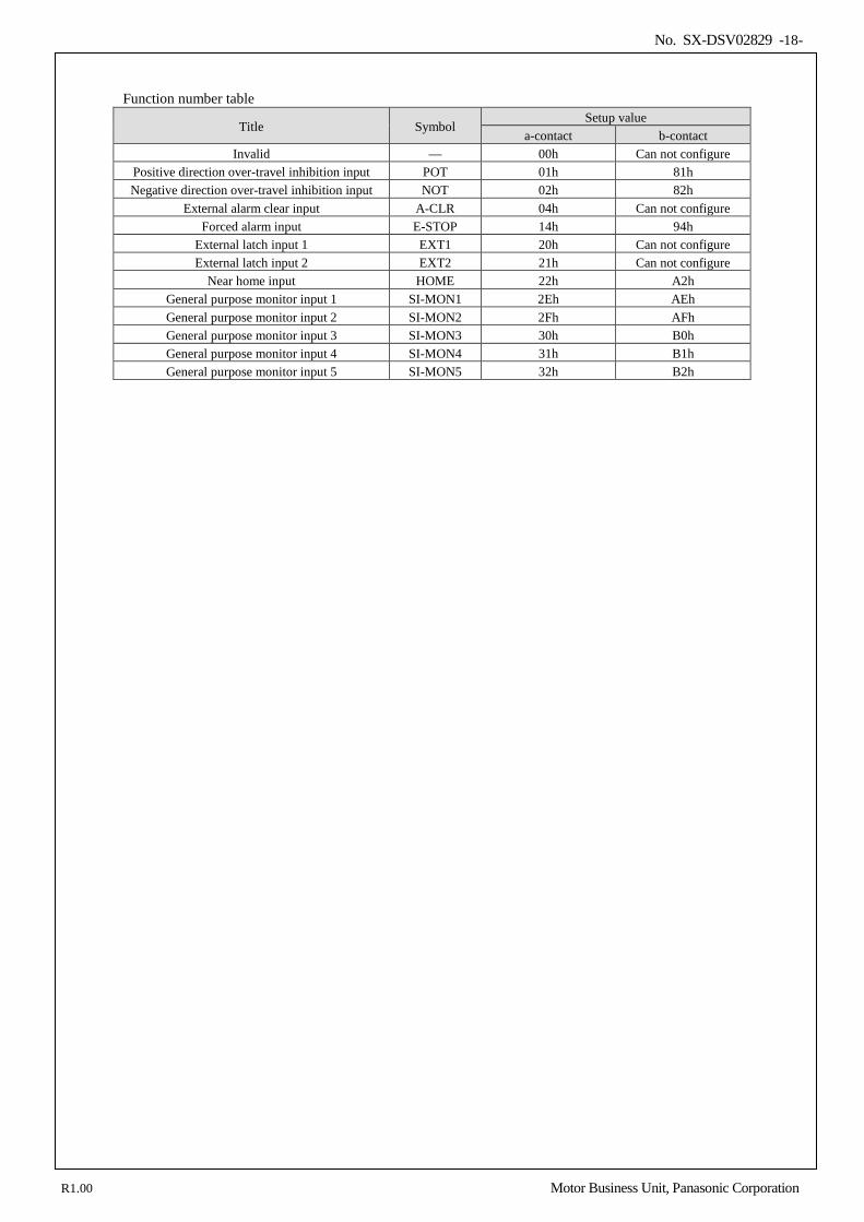
Function number table
Title Symbol Setup value
a-contact b-contact Invalid — 00h Can not configure
Positive direction over-travel inhibition input POT 01h 81h Negative direction over-travel inhibition input NOT 02h 82h
External alarm clear input A-CLR 04h Can not configure Forced alarm input E-STOP 14h 94h
External latch input 1 EXT1 20h Can not configure External latch input 2 EXT2 21h Can not configure
Near home input HOME 22h A2h General purpose monitor input 1 SI-MON1 2Eh AEh General purpose monitor input 2 SI-MON2 2Fh AFh General purpose monitor input 3 SI-MON3 30h B0h General purpose monitor input 4 SI-MON4 31h B1h General purpose monitor input 5 SI-MON5 32h B2h
R1.00 Motor Business Unit, Panasonic Corporation
No. SX-DSV02829 -19-
Precautions for input signal assignment
• Do not setup to a value other than that specified in the table.
• The same signal can’t be assigned to multiple pins. Otherwise, duplicated assignment will cause Err 33.0 “Input multiple assignment error 1 protection” or Err 33.1 “Input multiple assignment error 2 protection”.
• A signal used in multiple control modes should be assigned to the same pin and the logic should be matched. If not assigned to the same pin, the Err33.0 “Input duplicate assignment error 1 protection” or Err33.1 “Input duplicate assignment error 2 protection” occurs. In case that the logics do not match, Err33.2 “Input function number error 1 protection” or Err33.3 “Input function number error 2 protection” will occur.
• The duplicated assignment of SI-MON1 and EXT1, SI-MON2 and EXT2, SI-MON4 and EX-SON, and SI-MON5 and E-STOP is not allowed. Duplicate assignment will cause Err33.0 “Input duplicate assignment error 1 protection” or Err33.1 “Input duplicate assignment error 2 protection”.
• A-CLR can only be set at a-connect. If set at b-connect, then Err33.2 “Input function number assignment error 1 protection” or Err33.3 “Input function number assignment error 2 protection” will occur.
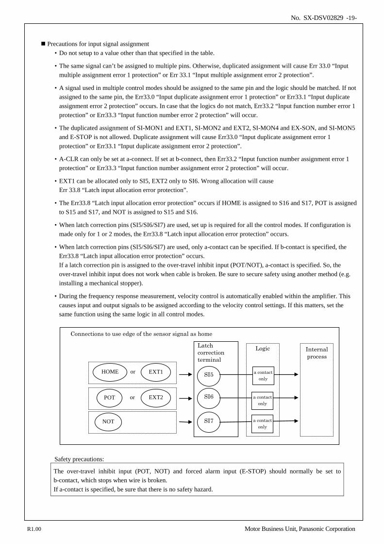
• EXT1 can be allocated only to SI5, EXT2 only to SI6. Wrong allocation will cause Err 33.8 “Latch input allocation error protection”.
• The Err33.8 “Latch input allocation error protection” occurs if HOME is assigned to S16 and S17, POT is assigned to S15 and S17, and NOT is assigned to S15 and S16.
• When latch correction pins (SI5/SI6/SI7) are used, set up is required for all the control modes. If configuration is made only for 1 or 2 modes, the Err33.8 “Latch input allocation error protection” occurs.
• When latch correction pins (SI5/SI6/SI7) are used, only a-contact can be specified. If b-contact is specified, the Err33.8 “Latch input allocation error protection” occurs. If a latch correction pin is assigned to the over-travel inhibit input (POT/NOT), a-contact is specified. So, the over-travel inhibit input does not work when cable is broken. Be sure to secure safety using another method (e.g. installing a mechanical stopper).
• During the frequency response measurement, velocity control is automatically enabled within the amplifier. This causes input and output signals to be assigned according to the velocity control settings. If this matters, set the same function using the same logic in all control modes.
Safety precautions:
The over-travel inhibit input (POT, NOT) and forced alarm input (E-STOP) should normally be set to b-contact, which stops when wire is broken. If a-contact is specified, be sure that there is no safety hazard.
Latch correction terminal
SI5
SI6
SI7
a contact only
Logic
a contact only
a contact only
Internal process
Connections to use edge of the sensor signal as home
EXT1
EXT2
NOT
or
or HOME
POT
R1.00 Motor Business Unit, Panasonic Corporation
No. SX-DSV02829 -20-
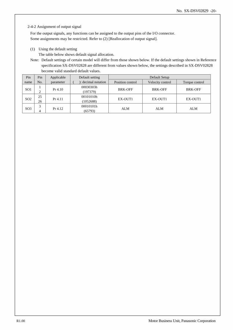
2-4-2 Assignment of output signal
For the output signals, any functions can be assigned to the output pins of the I/O connector. Some assignments may be restricted. Refer to (2) [Reallocation of output signal].
(1) Using the default setting
The table below shows default signal allocation. Note: Default settings of certain model will differ from those shown below. If the default settings shown in Reference
specification SX-DSV02828 are different from values shown below, the settings described in SX-DSV02828 become valid standard default values.
Pin name
Pin No.
Applicable parameter
Default setting ( ): decimal notation
Default Setup Position control Velocity control Torque control
SO1 1 2
Pr 4.10 00030303h (197379)
BRK-OFF BRK-OFF BRK-OFF
SO2 25 26
Pr 4.11 00101010h (1052688)
EX-OUT1 EX-OUT1 EX-OUT1
SO3 3 4
Pr 4.12 00010101h
(65793) ALM ALM ALM
R1.00 Motor Business Unit, Panasonic Corporation
No. SX-DSV02829 -21-
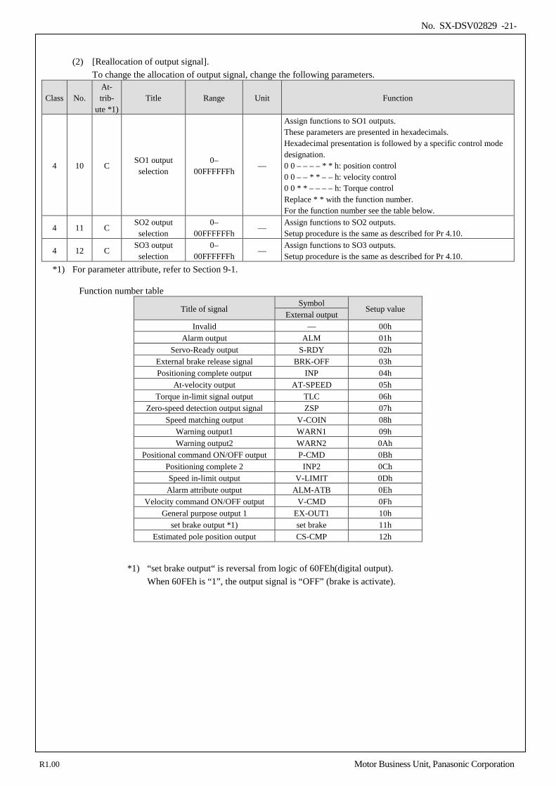
(2) [Reallocation of output signal].
To change the allocation of output signal, change the following parameters.
Class No. At- trib-
ute *1) Title Range Unit Function
4 10 C SO1 output
selection 0–
00FFFFFFh —
Assign functions to SO1 outputs. These parameters are presented in hexadecimals. Hexadecimal presentation is followed by a specific control mode designation. 0 0 – – – – * * h: position control 0 0 – – * * – – h: velocity control 0 0 * * – – – – h: Torque control Replace * * with the function number. For the function number see the table below.
4 11 C SO2 output
selection 0–
00FFFFFFh —
Assign functions to SO2 outputs. Setup procedure is the same as described for Pr 4.10.
4 12 C SO3 output
selection 0–
00FFFFFFh —
Assign functions to SO3 outputs. Setup procedure is the same as described for Pr 4.10.
*1) For parameter attribute, refer to Section 9-1.
Function number table
Title of signal Symbol
Setup value External output
Invalid — 00h Alarm output ALM 01h
Servo-Ready output S-RDY 02h External brake release signal BRK-OFF 03h Positioning complete output INP 04h
At-velocity output AT-SPEED 05h Torque in-limit signal output TLC 06h
Zero-speed detection output signal ZSP 07h Speed matching output V-COIN 08h
Warning output1 WARN1 09h Warning output2 WARN2 0Ah
Positional command ON/OFF output P-CMD 0Bh Positioning complete 2 INP2 0Ch Speed in-limit output V-LIMIT 0Dh Alarm attribute output ALM-ATB 0Eh
Velocity command ON/OFF output V-CMD 0Fh General purpose output 1 EX-OUT1 10h
set brake output *1) set brake 11h Estimated pole position output CS-CMP 12h
*1) “set brake output“ is reversal from logic of 60FEh(digital output). When 60FEh is “1”, the output signal is “OFF” (brake is activate).
R1.00 Motor Business Unit, Panasonic Corporation
No. SX-DSV02829 -22-
Precautions for output signal assignment
• For output signals, the same function can be assigned to multiple pins. However, the output logic setting must be the same. In addition, when using the same function for multiple control modes, the same output logic must be set. If different output logic was set, the output signal state will become unstable.
• For the output pins specified as disabled, output transistors are always turned off. However, EtherCAT communication response is not affected.
• Use only the values shown in the table above for setting. • When using external brake release signal (BRK-OFF) or set brake output, the signal should be set in all control modes.
If not applied to all control modes, Err 33.4 “Output function number error 1 protection” or Err 33.5 “Output function number error 2 protection” will occur.
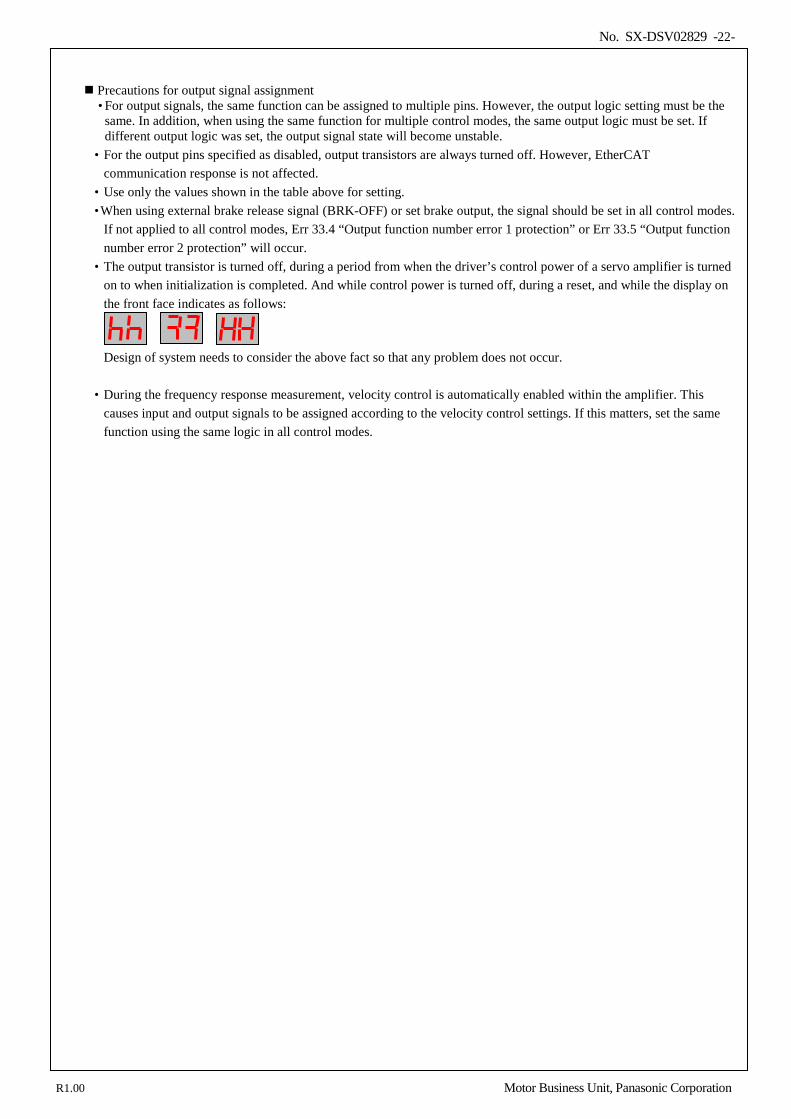
• The output transistor is turned off, during a period from when the driver’s control power of a servo amplifier is turned on to when initialization is completed. And while control power is turned off, during a reset, and while the display on the front face indicates as follows:
Design of system needs to consider the above fact so that any problem does not occur.
• During the frequency response measurement, velocity control is automatically enabled within the amplifier. This
causes input and output signals to be assigned according to the velocity control settings. If this matters, set the same function using the same logic in all control modes.
R1.00 Motor Business Unit, Panasonic Corporation
No. SX-DSV02829 -23-
3.Front panel display specification
3-1 Appearance of front panel ................................................................................................................................... 24 3-2 7-segment LED ................................................................................................................................................... 25 3-3 EtherCAT Indicators ........................................................................................................................................... 28 3-4 Monitor signal output function ............................................................................................................................ 30 3-5 Station alias ......................................................................................................................................................... 33
3
R1.00 Motor Business Unit, Panasonic Corporation
No. SX-DSV02829 -24-
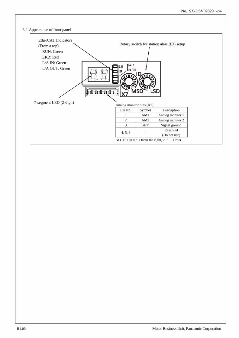
3-1 Appearance of front panel
7-segment LED (2-digit)
Rotary switch for station alias (ID) setup
Analog monitor pins (X7) Pin No. Symbol Description
1 AM1 Analog monitor 1 2 AM2 Analog monitor 2 3 GND Signal ground
4, 5, 6 - Reserved
(Do not use) NOTE: Pin No.1 from the right, 2, 3 ... Order
EtherCAT Indicators (From a top)
RUN: Green ERR: Red L/A IN: Green L/A OUT: Green
R1.00 Motor Business Unit, Panasonic Corporation
No. SX-DSV02829 -25-
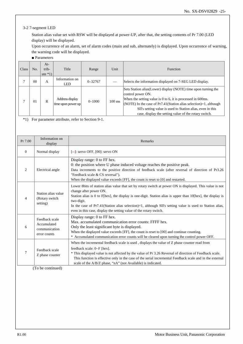
3-2 7-segment LED
Station alias value set with RSW will be displayed at power-UP, after that, the setting contents of Pr 7.00 (LED display) will be displayed. Upon occurrence of an alarm, set of alarm codes (main and sub, alternately) is displayed. Upon occurrence of warning, the warning code will be displayed. Parameters
Class No. At- trib-
ute *1) Title Range Unit Function
7 00 A Information on
LED 0–32767 — Selects the information displayed on 7-SEG LED display.
7 01 R Address display
time upon power up 0–1000 100 ms
Sets Station alias(Lower) display (NOTE) time upon turning the control power ON. When the setting value is 0 to 6, it is processed in 600ms. (NOTE) In the case of Pr7.41(Station alias selection)=1, although
SII's setting value is used to Station alias, even in this case, display the setting value of the rotary switch.
*1) For parameter attribute, refer to Section 9-1.
Pr 7.00 Information on
display Remarks
0 Normal display [--]: servo OFF, [00]: servo ON
2 Electrical angle
Display range: 0 to FF hex. 0: the position where U phase induced voltage reaches the positive peak. Data increments to the positive direction of feedback scale (after reversal of direction of Pr3.26 "Feedback scale & CS reversal"). When the displayed value exceeds [FF], the count is reset to [0] and restarted.
4 Station alias value (Rotary switch setting)
Lower 8bits of station alias value that set by rotary switch at power ON is displayed. This value is not change after power ON. Station alias is 0 to F[hex], the display is one-digit. Station alias is upper than 10[hex], the display is two-digit. In the case of Pr7.41(Station alias selection)=1, although SII's setting value is used to Station alias, even in this case, display the setting value of the rotary switch.
6
Feedback scale Accumulated communication error counts
Display range: 0 to FF hex. Max. accumulated communication error counts: FFFF hex. Only the least significant byte is displayed. When the displayed value exceeds [FF], the count is reset to [00] and continue counting. * Accumulated communication error counts will be cleared upon turning the control power OFF.
7 Feedback scale Z phase counter
When the incremental feedback scale is used , displays the value of Z phase counter read from feedback scale: 0−F [hex]. * This displayed value is not affected by the value of Pr 3.26 Reversal of direction of Feedback scale.
This function is effective only in the case of the serial incremental Feedback scale and in the external scale of the A/B/Z phase, “nA” (not Available) is indicated.
(To be continued)
R1.00 Motor Business Unit, Panasonic Corporation
No. SX-DSV02829 -26-
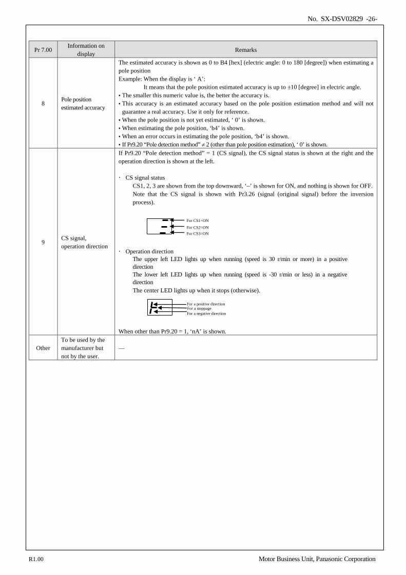
Pr 7.00 Information on
display Remarks
8 Pole position estimated accuracy
The estimated accuracy is shown as 0 to B4 [hex] (electric angle: 0 to 180 [degree]) when estimating a pole position Example: When the display is ‘ A’:
It means that the pole position estimated accuracy is up to ±10 [degree] in electric angle. The smaller this numeric value is, the better the accuracy is. This accuracy is an estimated accuracy based on the pole position estimation method and will not
guarantee a real accuracy. Use it only for reference. When the pole position is not yet estimated, ‘ 0’ is shown. When estimating the pole position, ‘b4’ is shown. When an error occurs in estimating the pole position, ‘b4’ is shown. If Pr9.20 “Pole detection method” ≠ 2 (other than pole position estimation), ‘ 0’ is shown.
9 CS signal, operation direction
If Pr9.20 “Pole detection method” = 1 (CS signal), the CS signal status is shown at the right and the operation direction is shown at the left. CS signal status
CS1, 2, 3 are shown from the top downward, ‘–’ is shown for ON, and nothing is shown for OFF. Note that the CS signal is shown with Pr3.26 (signal (original signal) before the inversion process).
Operation direction
The upper left LED lights up when running (speed is 30 r/min or more) in a positive direction The lower left LED lights up when running (speed is -30 r/min or less) in a negative direction The center LED lights up when it stops (otherwise).
When other than Pr9.20 = 1, ‘nA’ is shown.
Other To be used by the manufacturer but not by the user.
—
For CS1=ON For CS2=ON For CS3=ON
For a positive direction For a stoppage For a negative direction
R1.00 Motor Business Unit, Panasonic Corporation
No. SX-DSV02829 -27-
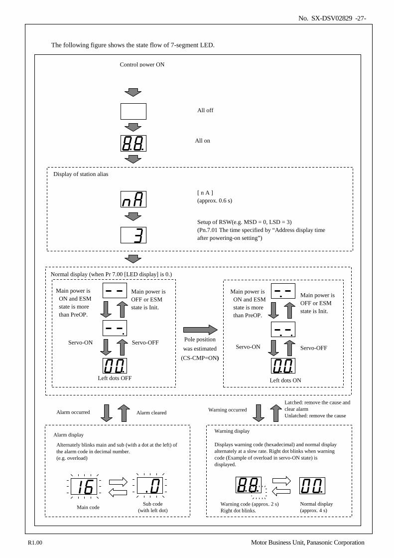
The following figure shows the state flow of 7-segment LED.
Control power ON
All off
All on
[ n A ] (approx. 0.6 s)
Setup of RSW(e.g. MSD = 0, LSD = 3) (Pn.7.01 The time specified by “Address display time after powering-on setting”)
Display of station alias
Normal display (when Pr 7.00 [LED display] is 0.)
Main power is ON and ESM state is more than PreOP.
Main power is OFF or ESM state is Init.
Servo-ON Servo-OFF
Alarm occurred Alarm cleared Warning occurred Latched: remove the cause and clear alarm Unlatched: remove the cause
Alarm display
Alternately blinks main and sub (with a dot at the left) of the alarm code in decimal number. (e.g. overload)
Warning display
Displays warning code (hexadecimal) and normal display alternately at a slow rate. Right dot blinks when warning code (Example of overload in servo-ON state) is displayed.
Warning code (approx. 2 s) Right dot blinks. Main code Sub code
(with left dot) Normal display (approx. 4 s)
Main power is ON and ESM state is more than PreOP.
Servo-ON Servo-OFF
Main power is OFF or ESM state is Init.
Pole position was estimated
(CS-CMP=ON)
Left dots OFF Left dots ON
R1.00 Motor Business Unit, Panasonic Corporation
No. SX-DSV02829 -28-
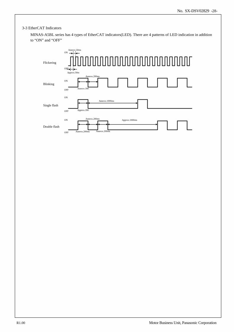
3-3 EtherCAT Indicators
MINAS-A5BL series has 4 types of EtherCAT indicators(LED). There are 4 patterns of LED indication in addition to “ON” and “OFF”
Flickering
Blinking
Single flash
Double flash
Approx.200
Approx.200
Approx.200ms
Approx.1000ms
Approx.1000ms
Approx.50m
Approx.50ms ON
OFF
OFF
ON
OFF
ON
OFF
ON Approx.200ms
Approx.200ms Approx.200ms
R1.00 Motor Business Unit, Panasonic Corporation
No. SX-DSV02829 -29-
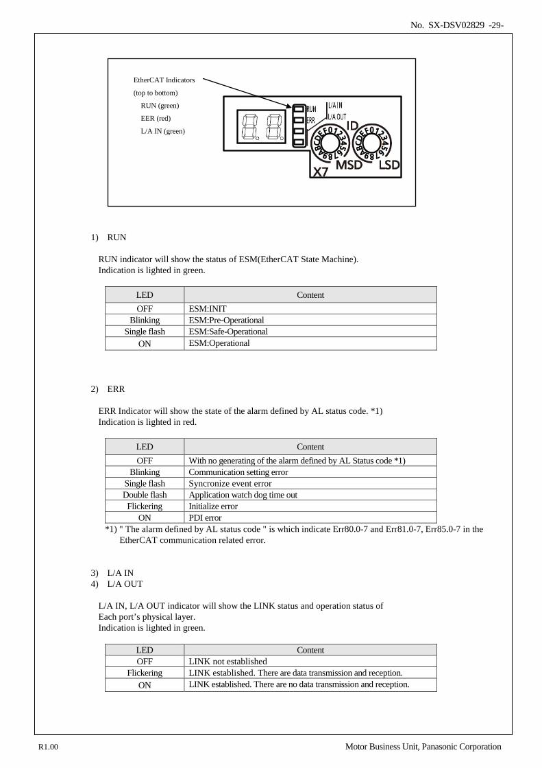
1) RUN
RUN indicator will show the status of ESM(EtherCAT State Machine). Indication is lighted in green.
LED Content OFF ESM:INIT
Blinking ESM:Pre-Operational Single flash ESM:Safe-Operational
ON ESM:Operational
2) ERR
ERR Indicator will show the state of the alarm defined by AL status code. *1) Indication is lighted in red.
LED Content OFF With no generating of the alarm defined by AL Status code *1)
Blinking Communication setting error Single flash Syncronize event error Double flash Application watch dog time out Flickering Initialize error
ON PDI error *1) " The alarm defined by AL status code " is which indicate Err80.0-7 and Err81.0-7, Err85.0-7 in the
EtherCAT communication related error.
3) L/A IN 4) L/A OUT
L/A IN, L/A OUT indicator will show the LINK status and operation status of Each port’s physical layer. Indication is lighted in green.
LED Content OFF LINK not established
Flickering LINK established. There are data transmission and reception. ON LINK established. There are no data transmission and reception.
EtherCAT Indicators
(top to bottom)
RUN (green)
EER (red)
L/A IN (green)
R1.00 Motor Business Unit, Panasonic Corporation
No. SX-DSV02829 -30-
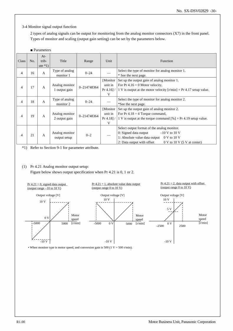
3-4 Monitor signal output function
2 types of analog signals can be output for monitoring from the analog monitor connectors (X7) in the front panel. Types of monitor and scaling (output gain setting) can be set by the parameters below.
Parameters
Class No. At- trib-
ute *1) Title Range Unit Function
4 16 A Type of analog
monitor 1 0–24 —
Select the type of monitor for analog monitor 1. * See the next page.
4 17 A Analog monitor
1 output gain 0–214748364
[Monitor unit in
Pr 4.16] / V
Set up the output gain of analog monitor 1. For Pr 4.16 = 0 Motor velocity, 1 V is output at the motor velocity [r/min] = Pr 4.17 setup value.
4 18 A Type of analog
monitor 2 0–24 —
Select the type of monitor for analog monitor 2. *See the next page.
4 19 A Analog monitor
2 output gain 0–214748364
[Monitor unit in
Pr 4.18] / V
Set up the output gain of analog monitor 2. For Pr 4.18 = 4 Torque command, 1 V is output at the torque command [%] = Pr 4.19 setup value.
4 21 A Analog monitor
output setup 0–2 —
Select output format of the analog monitor. 0: Signed data output –10 V to 10 V 1: Absolute value data output 0 V to 10 V 2: Data output with offset 0 V to 10 V (5 V at center)
*1) Refer to Section 9-1 for parameter attribute.
(1) Pr 4.21 Analog monitor output setup: Figure below shows output specification when Pr 4.21 is 0, 1 or 2.
Output voltage [V]
Motor speed [r/min]
10 V
-10 V
5000 -5000
Pr 4.21 = 0, signed data output (output range −10 to 10 V)
Output voltage [V]
Motor speed [r/min]
10 V
-10 V
5000 -5000
Pr 4.21 = 1, absolute value data output (output range 0 to 10 V)
Output voltage [V]
Motor speed [r/min]
10 V
-10 V
2500 -2500
Pr 4.21 = 2, data output with offset (output range 0 to 10 V)
0 V
0 V
0 V
• When monitor type is motor speed, and conversion gain is 500 (1 V = 500 r/min).
5 V
R1.00 Motor Business Unit, Panasonic Corporation
No. SX-DSV02829 -31-
(2) The table below shows types of monitor set in Pr 4.16 “Type of analog monitor 1” and Pr 4.18 “Type of analog monitor 2”. Pr 4.17 “Analog monitor 1 output gain” and Pr 4.19 “Analog monitor 2 output gain” respectively set the conversion gain in accordance to the unit suitable for the type. When the gain is set to 0, the gain shown at the right end column of the table is automatically applied.
Pr 4.16/Pr 4.18 Type of monitor Unit Output gain for setting
Pr 4.17/Pr 4.19 = 0 0 Motor velocity r/min 500 1 Positional command velocity *2 r/min 500 2 Internal positional command velocity *2 r/min 500 3 Velocity control command r/min 500 4 Torque command % 33 5 Command positional deviation *3 pulse (feedback scale unit) 3000 6 Encoder positional deviation *3 pulse (feedback scale unit) 3000 7 Reserved — — 8 Reserved — — 9 Voltage across PN V 80 10 Regenerative load factor % 33 11 Overload factor % 33 12 Positive direction torque limit % 33 13 Negative direction torque limit % 33 14 Speed limit value r/min 500 15 Inertia ratio % 500 16 Reserved — — 17 Reserved — — 18 Reserved — — 19 Reserved — — 20 Driver temperature °C 10 21 Reserved — — 22 Reserved — — 23 Travel command status *4 — — 24 Gain selection status *4 — —
*1 The positive/negative direction of monitor data does not follow the polarity setting, and the positive direction of
feedback scale (after reversal of direction of Pr3.26 "Feedback scale & CS reversal") always serves as positive. When the incremental Feedback Scale is used, a normal value is output after it passes through the first Z phase.
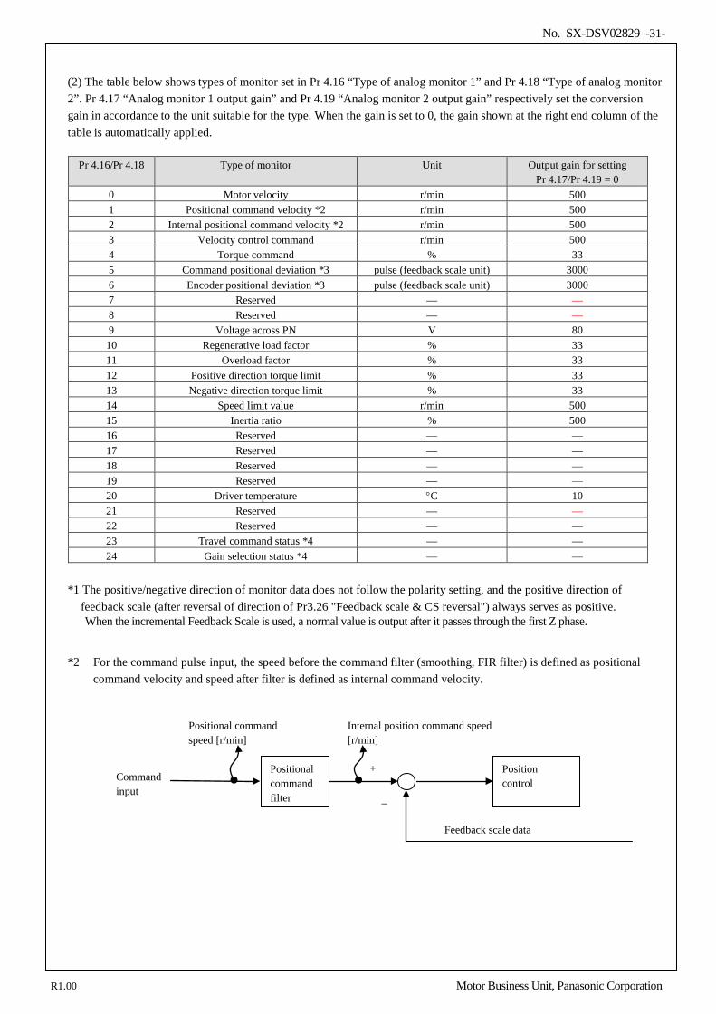
*2 For the command pulse input, the speed before the command filter (smoothing, FIR filter) is defined as positional command velocity and speed after filter is defined as internal command velocity.
Positional command filter
Position control
Feedback scale data
+
–
Internal position command speed [r/min]
Positional command speed [r/min]
Command input
R1.00 Motor Business Unit, Panasonic Corporation
No. SX-DSV02829 -32-
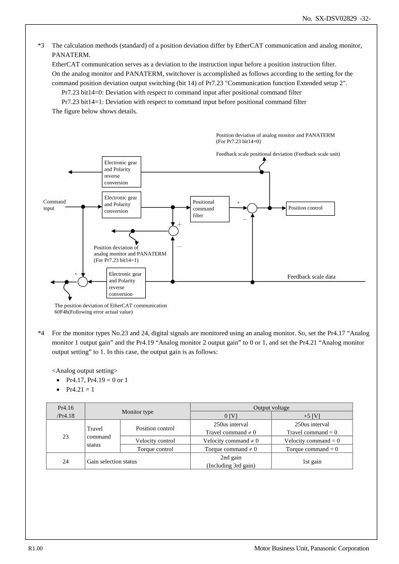
*3 The calculation methods (standard) of a position deviation differ by EtherCAT communication and analog monitor,
PANATERM. EtherCAT communication serves as a deviation to the instruction input before a position instruction filter. On the analog monitor and PANATERM, switchover is accomplished as follows according to the setting for the command position deviation output switching (bit 14) of Pr7.23 "Communication function Extended setup 2". Pr7.23 bit14=0: Deviation with respect to command input after positional command filter Pr7.23 bit14=1: Deviation with respect to command input before positional command filter The figure below shows details.
*4 For the monitor types No.23 and 24, digital signals are monitored using an analog monitor. So, set the Pr4.17 “Analog monitor 1 output gain” and the Pr4.19 “Analog monitor 2 output gain” to 0 or 1, and set the Pr4.21 “Analog monitor output setting” to 1. In this case, the output gain is as follows:
<Analog output setting> • Pr4.17, Pr4.19 = 0 or 1 • Pr4.21 = 1
Pr4.16 /Pr4.18
Monitor type Output voltage
0 [V] +5 [V]
23 Travel command status
Position control 250us interval
Travel command ≠ 0 250us interval
Travel command = 0 Velocity control Velocity command ≠ 0 Velocity command = 0 Torque control Torque command ≠ 0 Torque command = 0
24 Gain selection status 2nd gain
(Including 3rd gain) 1st gain
Positional command filter
Position control
Feedback scale data
+
–
Command input
Position deviation of analog monitor and PANATERM (For Pr7.23 bit14=0) Feedback scale positional deviation (Feedback scale unit)
+ –
The position deviation of EtherCAT communication 60F4h(Following error actual value)
Position deviation of analog monitor and PANATERM (For Pr7.23 bit14=1)
Electronic gear and Polarity reverse conversion
Electronic gear and Polarity reverse conversion
Electronic gear and Polarity conversion
+
-
R1.00 Motor Business Unit, Panasonic Corporation
No. SX-DSV02829 -33-
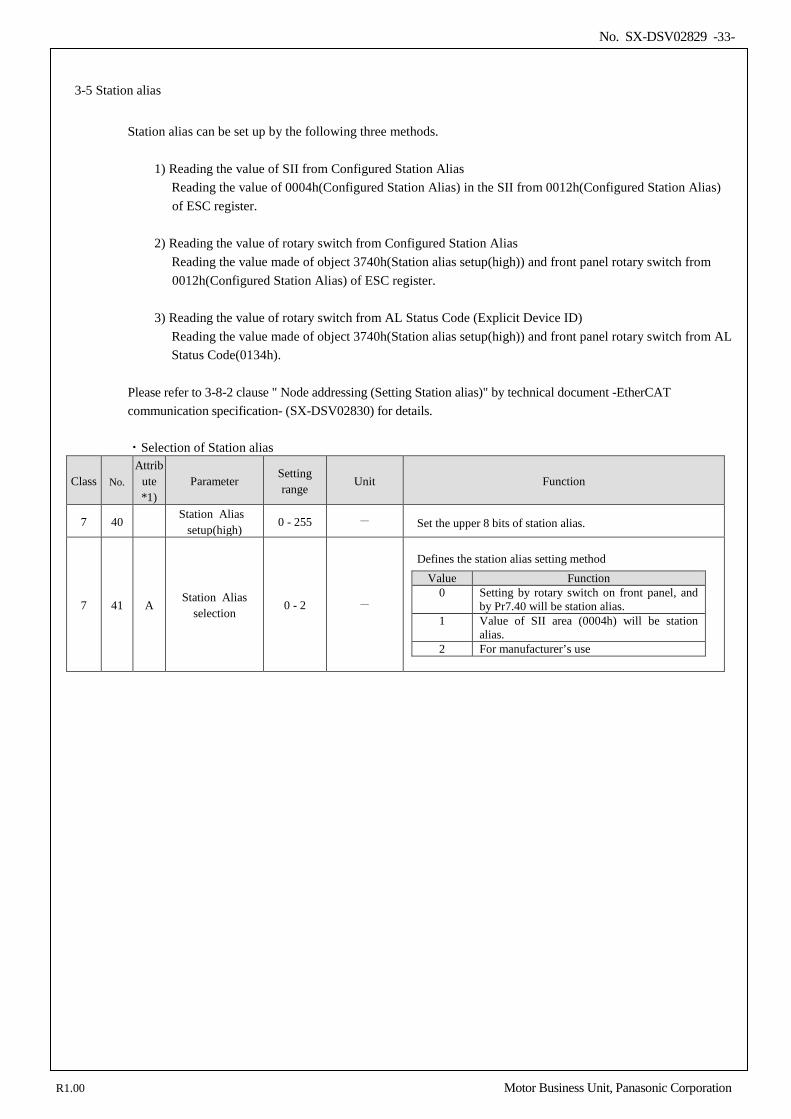
3-5 Station alias
Station alias can be set up by the following three methods. 1) Reading the value of SII from Configured Station Alias
Reading the value of 0004h(Configured Station Alias) in the SII from 0012h(Configured Station Alias) of ESC register.
2) Reading the value of rotary switch from Configured Station Alias
Reading the value made of object 3740h(Station alias setup(high)) and front panel rotary switch from 0012h(Configured Station Alias) of ESC register.
3) Reading the value of rotary switch from AL Status Code (Explicit Device ID)
Reading the value made of object 3740h(Station alias setup(high)) and front panel rotary switch from AL Status Code(0134h).
Please refer to 3-8-2 clause " Node addressing (Setting Station alias)" by technical document -EtherCAT communication specification- (SX-DSV02830) for details. ・Selection of Station alias
Class No. Attrib
ute *1)
Parameter Setting range
Unit Function
7 40 Station Alias
setup(high) 0 - 255 - Set the upper 8 bits of station alias.
7 41 A Station Alias
selection 0 - 2 -
Defines the station alias setting method
Value Function 0 Setting by rotary switch on front panel, and
by Pr7.40 will be station alias. 1 Value of SII area (0004h) will be station
alias. 2 For manufacturer’s use
R1.00 Motor Business Unit, Panasonic Corporation
No. SX-DSV02829 -34-
4.Basic function
4-1 Operation direction setup .................................................................................................................................... 35 4-2 Position control ................................................................................................................................................... 36 4-2-1 Process of command pulse input .................................................................................................................... 36 4-2-2 Electronic gear function ................................................................................................................................. 37 4-2-3 Positional command filtering function ........................................................................................................... 40 4-2-4 Positioning complete output (INP/INP2) function ......................................................................................... 42 4-2-5 Pulse regeneration function (Some models not supported) ......................................................................... 44
4-3 Velocity Control .................................................................................................................................................. 47 4-3-1 Attained speed output (AT-SPEED) .............................................................................................................. 47 4-3-2 Speed coincidence output (V-COIN) ............................................................................................................. 48 4-3-3 Velocity command acceleration/deceleration setting function ....................................................................... 49
4-4 Toruqe control ..................................................................................................................................................... 51 4-4-1 Speed limit function ....................................................................................................................................... 51
4-5 Setting regenerative resistor ................................................................................................................................ 52 4-6 Absolute setup ..................................................................................................................................................... 53 4-6-1 Feedback scale ............................................................................................................................................... 53
4-7 Linear motor/feedback scale setting .................................................................................................................... 54 4-7-1 Parameter setting according to linear motor/feedback scale specification ..................................................... 55 4-7-2 Current gain setting ........................................................................................................................................ 60 4-7-3 Pole position detection method setting ........................................................................................................... 61 4-7-4 Automatic linear motor setting with tool ....................................................................................................... 68
4
R1.00 Motor Business Unit, Panasonic Corporation

No. SX-DSV02829 -35-
4-1 Operation direction setup
As opposed to position instructions / speed instructions / Torque instructions, and each offset, Polarity (Operation direction) can be set up. In MINAS-A5BL series, a setup of the hand of cut by parameter Pr0.00 (Operation direction) has not corresponded, the hand of cut is set up by object 607Eh (Polarity) specified to CoE (CiA402). Please refer to section 6-9-4 "3) Polarity(607Eh)" of Technical Document "EtherCAT Communication Specifications" (SX-DSV02830) for details of object 607Eh (Polarity).
Setting value Description 0 No reverse of sign of torque, velocity, position
224 Reverse of sign of torque, velocity, and position possible Other than above Not supported (Do not set)
In addition, object 607Eh (Polarity) is not what replaced parameter Pr0.00 (hand-of-cut setup) as it was, It becomes effective when performing the following data transfer between a CoE (CiA402) process division and a motor control process division.
< Instructions / setting > - 607Ah(Target position) - 60B0h(Position offset) - 60FFh(Target velocity) - 60B1h(Velocity offset) - 6071h(Target torque) - 60B2h(Torque offset)
<Monitor > - 6062h(Position demand value) - 6064h(Position actual value) - 606Bh(Velocity demand value) - 606Ch(Velocity actual value) - 6074h(Torque demand) - 6077h(Torque actual value)
< External input > - 60FDh-00h(Digital input) is bit1(positive limit switch(POT)) - 60FDh-00h(Digital input) is bit0(negative limit switch(NOT))
Data other than the above, for example, such as data on setup support tool PANATERM, are set to fixed values regardless of the setting of 607Eh (Polarity), where the positive direction is the direction in which the feedback scale count is counted up positively. With regard to POT and NOT during operation from PANATERM such as trial operation, frequency characteristics analysis, POT is enabled when the operation is made in the direction in which the feedback scale count is counted up positively. When 607Eh(Polarity) is setting to reverse of sign, When you perform a test run etc., please be careful of the logic of the ban on a drive.
PANATERM
607Eh-00h
Polarity
60FDh(POT/NOT)
Pr0.00
(Not supported)
=
not reversed
The positive direction is the direction in which the feedback scale count is counted up positively.
Motor control Processing CoE(CiA402) Processing
Instructions / setting such as 607Ah
External input (POT/NOT)
Monitor such as 6062h
Instructions / setting other than 607Ah etc.
Monitor other than 6062h etc.
R1.00 Motor Business Unit, Panasonic Corporation
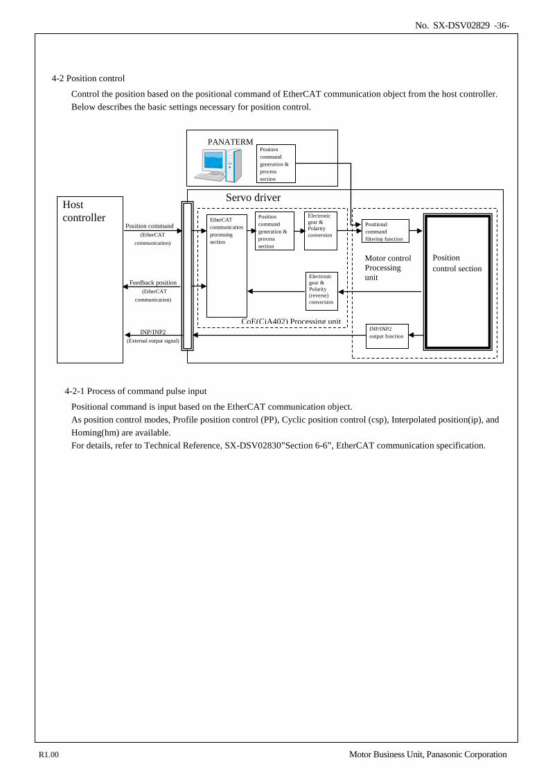
No. SX-DSV02829 -36-
4-2 Position control
Control the position based on the positional command of EtherCAT communication object from the host controller. Below describes the basic settings necessary for position control.
4-2-1 Process of command pulse input
Positional command is input based on the EtherCAT communication object. As position control modes, Profile position control (PP), Cyclic position control (csp), Interpolated position(ip), and Homing(hm) are available. For details, refer to Technical Reference, SX-DSV02830”Section 6-6”, EtherCAT communication specification.
Servo driver
Position command (EtherCAT
communication)
Position command generation & process section
EtherCAT communication processing section
Host controller
Positional command filtering function
Position control section
INP/INP2 (External output signal)
INP/INP2 output function
Electronic gear & Polarity conversion
Electronic gear & Polarity (reverse) conversion
Feedback position (EtherCAT
communication)
CoE(CiA402) Processing unit
Motor control Processing unit
PANATERM Position command generation & process section
R1.00 Motor Business Unit, Panasonic Corporation
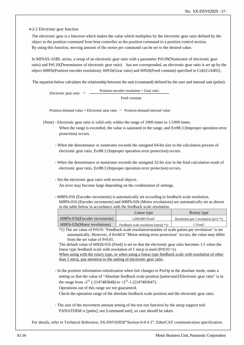
No. SX-DSV02829 -37-
4-2-2 Electronic gear function
The electronic gear is a function which makes the value which multiplies by the electronic gear ratio defined by the object to the position command from host controller as the position command to a position control section. By using this function, moving amount of the motor per command can be set to the desired value. In MINAS-A5BL series, a setup of an electronic gear ratio with a parameter Pr0.09(Numerator of electronic gear ratio) and Pr0.10(Denominator of electronic gear ratio) has not corresponded, an electronic gear ratio is set up by the object 608Fh(Position encoder resolution), 6091h(Gear ratio) and 6092h(Feed constant) specified to CoE(CiA402). The equation below calculates the relationship between the unit (command) defined by the user and internal unit (pulse):
(Note) - Electronic gear ratio is valid only within the range of 1000 times to 1/1000 times. When the range is exceeded, the value is saturated in the range, and Err88.3 (Improper operation error protection) occurs.
- When the denominator or numerator exceeds the unsigned 64-bit size in the calculation process of electronic gear ratio, Err88.3 (Improper operation error protection) occurs.
- When the denominator or numerator exceeds the unsigned 32-bit size in the final calculation result of
electronic gear ratio, Err88.3 (Improper operation error protection) occurs. - Set the electronic gear ratio with several objects.
An error may become large depending on the combination of settings.
- 608Fh-01h (Encoder increments) is automatically set according to feedback scale resolution. 608Fh-01h (Encoder increments) and 608Fh-02h (Motor revolutions) are automatically set as shown in the table below in accordance with the feedback scale resolution. Linear type Rotary type 608Fh-01h(Encoder increments) 1,000,000(fixed) Resolution per 1 revolution [p/r] *1)
608Fh-02h(Motor revolutions) Feedback scale resolution [nm/p] *1) 1(fixed) *1) The set value of Pr9.01 "Feedback scale resolution/number of scale pulses per revolution" is set
automatically. However, if Err60.0 "Motor setting error protection" occurs, the value may differ from the set value of Pr9.01.
The default value of 6092h-01h (Feed) is set so that the electronic gear ratio becomes 1:1 when the linear type feedback scale with resolution of 1 nm/p is used (Pr9.01=1). When using with the rotary type, or when using a linear type feedback scale with resolution of other than 1 nm/p, pay attention to the setting of electronic gear ratio.
- In the position information initialization when Init changes to PreOp in the absolute mode, make a setting so that the value of "Absolute feedback scale position [pulse/unit]/Electronic gear ratio" is in the range from -231 (-2147483648) to +231-1 (2147483647). Operations out of this range are not guaranteed. Check the operation range of the absolute feedback scale position and the electronic gear ratio.
- The unit of the movement amount setting of the test run function by the setup support tool
PANATERM is [pulse], not [command unit], so care should be taken. For details, refer to Technical Reference, SX-DSV02830”Section 6-9-4 2”, EtherCAT communication specification.
Position demand value × Electronic gear ratio = Position demand internal value
Feed constant
Position encoder resolution × Gear ratio Electronic gear ratio =
R1.00 Motor Business Unit, Panasonic Corporation
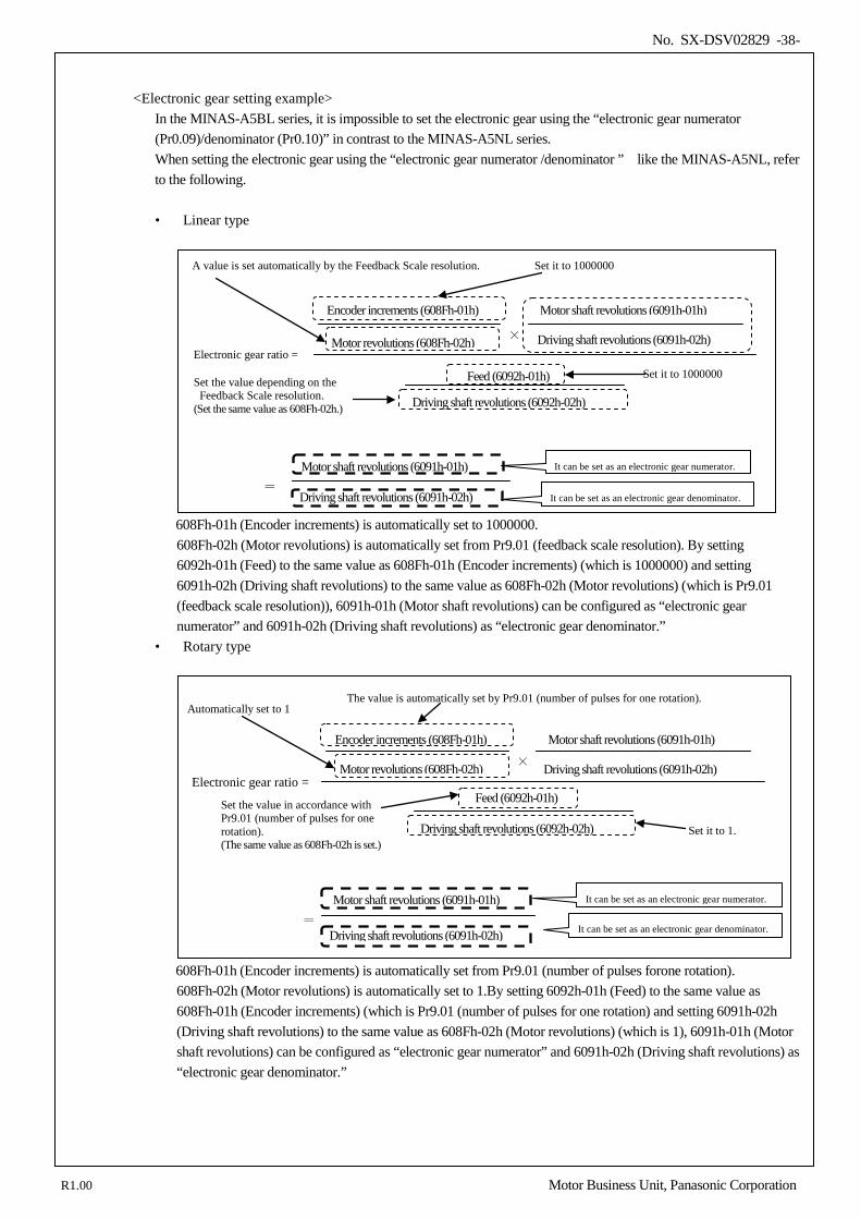
No. SX-DSV02829 -38-
<Electronic gear setting example> In the MINAS-A5BL series, it is impossible to set the electronic gear using the “electronic gear numerator (Pr0.09)/denominator (Pr0.10)” in contrast to the MINAS-A5NL series. When setting the electronic gear using the “electronic gear numerator /denominator ” like the MINAS-A5NL, refer to the following. • Linear type
608Fh-01h (Encoder increments) is automatically set to 1000000. 608Fh-02h (Motor revolutions) is automatically set from Pr9.01 (feedback scale resolution). By setting 6092h-01h (Feed) to the same value as 608Fh-01h (Encoder increments) (which is 1000000) and setting 6091h-02h (Driving shaft revolutions) to the same value as 608Fh-02h (Motor revolutions) (which is Pr9.01 (feedback scale resolution)), 6091h-01h (Motor shaft revolutions) can be configured as “electronic gear numerator” and 6091h-02h (Driving shaft revolutions) as “electronic gear denominator.”
• Rotary type
608Fh-01h (Encoder increments) is automatically set from Pr9.01 (number of pulses forone rotation). 608Fh-02h (Motor revolutions) is automatically set to 1.By setting 6092h-01h (Feed) to the same value as 608Fh-01h (Encoder increments) (which is Pr9.01 (number of pulses for one rotation) and setting 6091h-02h (Driving shaft revolutions) to the same value as 608Fh-02h (Motor revolutions) (which is 1), 6091h-01h (Motor shaft revolutions) can be configured as “electronic gear numerator” and 6091h-02h (Driving shaft revolutions) as “electronic gear denominator.”
Electronic gear ratio =
The value is automatically set by Pr9.01 (number of pulses for one rotation).
It can be set as an electronic gear denominator.
×
Encoder increments (608Fh-01h)
Motor revolutions (608Fh-02h) Driving shaft revolutions (6091h-02h)
Motor shaft revolutions (6091h-01h)
Feed (6092h-01h)
Driving shaft revolutions (6092h-02h) Set it to 1.
= Driving shaft revolutions (6091h-02h)
Motor shaft revolutions (6091h-01h)
Set the value in accordance with Pr9.01 (number of pulses for one rotation). (The same value as 608Fh-02h is set.)
It can be set as an electronic gear numerator.
Automatically set to 1
Electronic gear ratio = ×
Encoder increments (608Fh-01h)
Motor revolutions (608Fh-02h) Driving shaft revolutions (6091h-02h)
Motor shaft revolutions (6091h-01h)
Feed (6092h-01h)
Driving shaft revolutions (6092h-02h)
= Driving shaft revolutions (6091h-02h)
Motor shaft revolutions (6091h-01h)
Set it to 1000000
It can be set as an electronic gear numerator.
Set it to 1000000 A value is set automatically by the Feedback Scale resolution.
Set the value depending on the Feedback Scale resolution. (Set the same value as 608Fh-02h.)
It can be set as an electronic gear denominator.
R1.00 Motor Business Unit, Panasonic Corporation
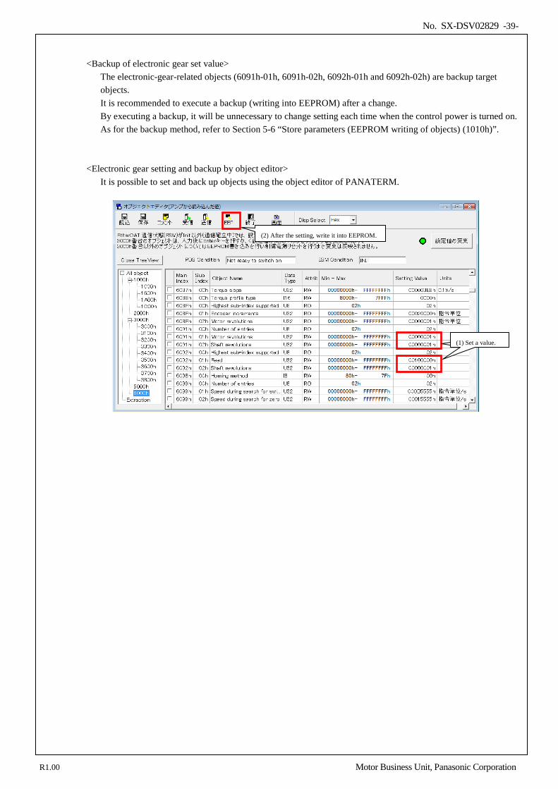
No. SX-DSV02829 -39-
<Backup of electronic gear set value> The electronic-gear-related objects (6091h-01h, 6091h-02h, 6092h-01h and 6092h-02h) are backup target objects. It is recommended to execute a backup (writing into EEPROM) after a change. By executing a backup, it will be unnecessary to change setting each time when the control power is turned on. As for the backup method, refer to Section 5-6 “Store parameters (EEPROM writing of objects) (1010h)”.
<Electronic gear setting and backup by object editor> It is possible to set and back up objects using the object editor of PANATERM.
①値を設定 (1) Set a value.
(2) After the setting, write it into EEPROM.
R1.00 Motor Business Unit, Panasonic Corporation
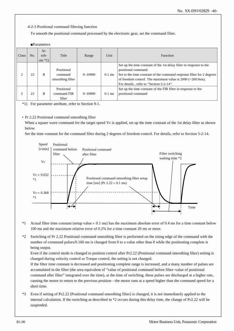
No. SX-DSV02829 -40-
4-2-3 Positional command filtering function
To smooth the positional command processed by the electronic gear, set the command filter.
Parameters
Class No. At- trib-
ute *1) Title Range Unit Function
2 22 B Positional command
smoothing filter 0–10000 0.1 ms
Set up the time constant of the 1st delay filter in response to the positional command. Set to the time constant of the command response filter for 2 degrees of freedom control. The maximum value is 2000 (=200.0ms). For details , refer to ”Section 5-2-14”.
2 23 B Positional
command FIR filter
0–10000 0.1 ms Set up the time constant of the FIR filter in response to the positional command
*1) For parameter attribute, refer to Section 9-1.
• Pr 2.22 Positional command smoothing filter
When a square wave command for the target speed Vc is applied, set up the time constant of the 1st delay filter as shown below. Set the time constant for the command filter during 2 degrees of freedom control. For details, refer to Section 5-2-14.
*1 Actual filter time constant (setup value × 0.1 ms) has the maximum absolute error of 0.4 ms for a time constant below 100 ms and the maximum relative error of 0.2% for a time constant 20 ms or more.
*2 Switching of Pr 2.22 Positional command smoothing filter is performed on the rising edge of the command with the number of command pulses/0.166 ms is changed from 0 to a value other than 0 while the positioning complete is being output. Even if the control mode is changed to position control after Pr2.22 (Positional command smoothing filter) setting is changed during velocity control or Torque control, the setting is not changed. If the filter time constant is decreased and positioning complete range is increased, and a many number of pulses are accumulated in the filter (the area equivalent of “value of positional command before filter–value of positional command after filter” integrated over the time), at the time of switching, these pulses are discharged at a higher rate, causing the motor to return to the previous position—the motor runs at a speed higher than the command speed for a short time.
*3 Even if setting of Pr2.22 (Positional command smoothing filter) is changed, it is not immediately applied to the internal calculation. If the switching as described in *2 occurs during this delay time, the change of Pr2.22 will be suspended.
Speed [r/min]
Vc
Vc × 0.632 *1 Positional command smoothing filter setup
time [ms] (Pr 2.22 × 0.1 ms)
Vc × 0.368 *1
Time
Positional command before filter
Positional command after filter Filter switching
waiting time *2
R1.00 Motor Business Unit, Panasonic Corporation
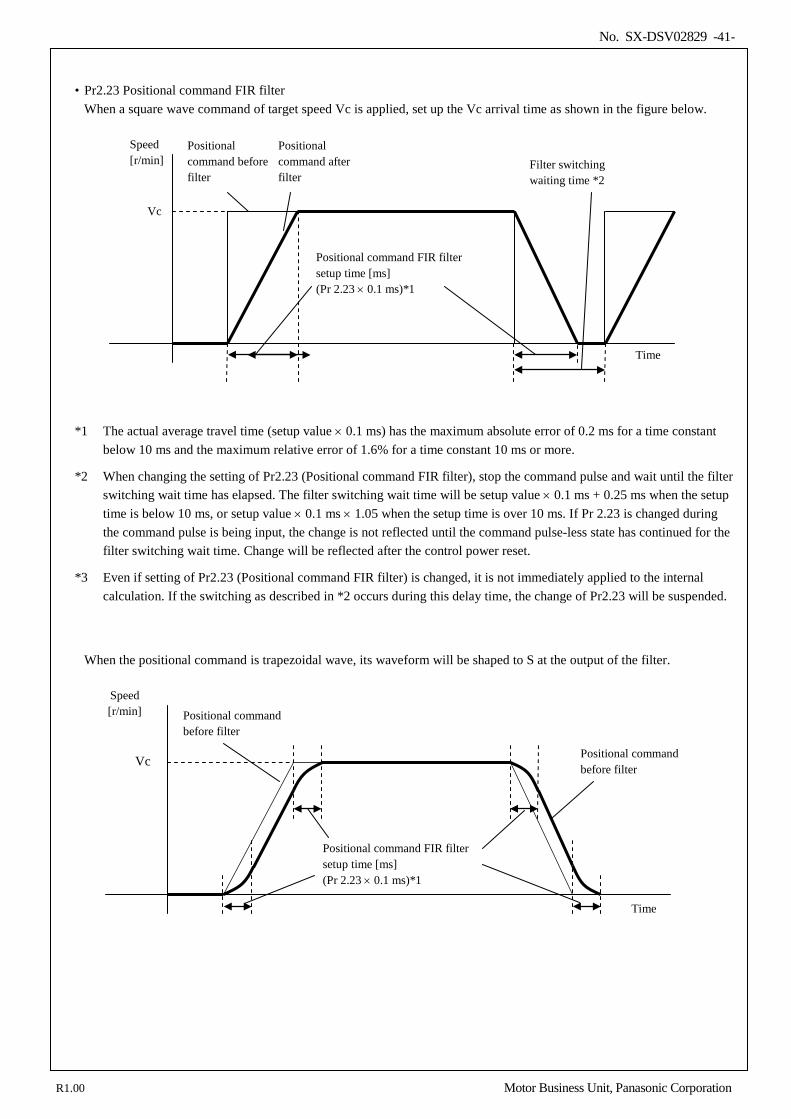
No. SX-DSV02829 -41-
• Pr2.23 Positional command FIR filter
When a square wave command of target speed Vc is applied, set up the Vc arrival time as shown in the figure below.
*1 The actual average travel time (setup value × 0.1 ms) has the maximum absolute error of 0.2 ms for a time constant below 10 ms and the maximum relative error of 1.6% for a time constant 10 ms or more.
*2 When changing the setting of Pr2.23 (Positional command FIR filter), stop the command pulse and wait until the filter switching wait time has elapsed. The filter switching wait time will be setup value × 0.1 ms + 0.25 ms when the setup time is below 10 ms, or setup value × 0.1 ms × 1.05 when the setup time is over 10 ms. If Pr 2.23 is changed during the command pulse is being input, the change is not reflected until the command pulse-less state has continued for the filter switching wait time. Change will be reflected after the control power reset.
*3 Even if setting of Pr2.23 (Positional command FIR filter) is changed, it is not immediately applied to the internal calculation. If the switching as described in *2 occurs during this delay time, the change of Pr2.23 will be suspended.
When the positional command is trapezoidal wave, its waveform will be shaped to S at the output of the filter.
Speed [r/min]
Vc
Positional command FIR filter setup time [ms] (Pr 2.23 × 0.1 ms)*1
Time
Positional command before filter
Positional command before filter
Speed [r/min]
Vc
Positional command FIR filter setup time [ms] (Pr 2.23 × 0.1 ms)*1
Time
Positional command before filter
Positional command after filter
Filter switching waiting time *2
R1.00 Motor Business Unit, Panasonic Corporation
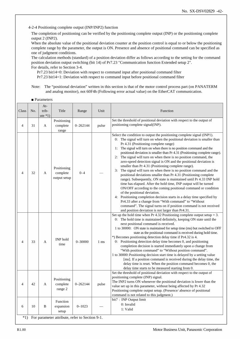
No. SX-DSV02829 -42-
4-2-4 Positioning complete output (INP/INP2) function
The completion of positioning can be verified by the positioning complete output (INP) or the positioning complete output 2 (INP2). When the absolute value of the positional deviation counter at the position control is equal to or below the positioning complete range by the parameter, the output is ON. Presence and absence of positional command can be specified as one of judgment conditions. The calculation methods (standard) of a position deviation differ as follows according to the setting for the command position deviation output switching (bit 14) of Pr7.23 "Communication function Extended setup 2". For details, refer to Section 3-4.
Pr7.23 bit14=0: Deviation with respect to command input after positional command filter Pr7.23 bit14=1: Deviation with respect to command input before positional command filter
Note: The “positional deviation” written in this section is that of the motor control process part (on PANATERM and analog monitor), not 60F4h (Following error actual value) on the EtherCAT communication.
Parameters
Class No. At- trib-
ute *1) Title Range Unit Function
4 31 A Positioning complete
range 0–262144 pulse
Set the threshold of positional deviation with respect to the output of positioning complete signal(INP).
4 32 A Positioning complete
output setup 0–4 —
Select the condition to output the positioning complete signal (INP1). 0: The signal will turn on when the positional deviation is smaller than
Pr 4.31 (Positioning complete range) 1: The signal will turn on when there is no position command and the
positional deviation is smaller than Pr 4.31 (Positioning complete range). 2: The signal will turn on when there is no position command, the
zero-speed detection signal is ON and the positional deviation is smaller than Pr 4.31 (Positioning complete range).
3: The signal will turn on when there is no position command and the positional deviations smaller than Pr 4.31 (Positioning complete range). Subsequently, ON state is maintained until Pr 4.33 INP hold time has elapsed. After the hold time, INP output will be turned ON/OFF according to the coming positional command or condition of the positional deviation.
4: Positioning completion decision starts in a delay time specified by Pr4.33 after a change from “With command” to “Without command”. The signal turns on if position command is not received and position deviation is not larger than Pr4.31.
4 33 A INP hold
time 0–30000 1 ms
Set up the hold time when Pr 4.32 Positioning complete output setup = 3. 0: The hold time is maintained definitely, keeping ON state until the
next positional command is received. 1 to 30000: ON state is maintained for setup time (ms) but switched to OFF
state as the positional command is received during hold time. *) Becomes positioning detection delay time if Pr4.32 is 4.
0: Positioning detection delay time becomes 0, and positioning completion decision is started immediately upon a change from “With position command” to “Without position command”.
1 to 30000: Positioning decision start time is delayed by a setting value [ms]. If a position command is received during the delay time, the delay time is reset. When the position command becomes 0, the delay time starts to be measured starting from 0.
4 42 A Positioning complete range 2
0–262144 pulse
Set the threshold of positional deviation with respect to the output of positioning complete (INP) signal. The INP2 turns ON whenever the positional deviation is lower than the value set up in this parameter, without being affected by Pr 4.32 Positioning complete output setup. (Presence/ absence of positional command is not related to this judgment.)
6 10 B Function
expansion setup
0–1023 —
bit7:INP Output limit 0: Invalid 1: Valid
*1) For parameter attribute, refer to Section 9-1.
R1.00 Motor Business Unit, Panasonic Corporation
No. SX-DSV02829 -43-
• The positional command is detected based on the command after the positional command filter. For positional command filter, refer to 4-2-3 Positional command filtering function.
Note: If Pr9.20 “Pole detection method” = 2 (Pole position estimation) and bit7 = 1 for Pr6.10 “Function expansion setup”,
the positioning complete signals 1 (INP1) and 2 (INP2) are turned OFF forcibly until the pole position estimation is finished.
R1.00 Motor Business Unit, Panasonic Corporation
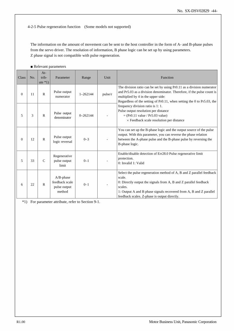
No. SX-DSV02829 -44-
4-2-5 Pulse regeneration function (Some models not supported)
The information on the amount of movement can be sent to the host controller in the form of A- and B-phase pulses from the servo driver. The resolution of information, B phase logic can be set up by using parameters. Z phase signal is not compatible with pulse regeneration. Relevant parameters
Class No. At- trib-
ute *1) Parameter Range Unit Function
0 11 R Pulse output numerator
1–262144 pulse/r
The division ratio can be set by using Pr0.11 as a division numerator and Pr5.03 as a division denominator. Therefore, if the pulse count is multiplied by 4 in the upper side: Regardless of the setting of Pr0.11, when setting the 0 to Pr5.03, the frequency division ratio is 1: 1. Pulse output resolution per distance
= (Pr0.11 value / Pr5.03 value) × Feedback scale resolution per distance
5 3 R Pulse output denominator 0–262144 -
0 12 R Pulse output logic reversal
0–3 -
You can set up the B-phase logic and the output source of the pulse output. With this parameter, you can reverse the phase relation between the A-phase pulse and the B-phase pulse by reversing the B-phase logic.
5 33 C Regenerative pulse output
limit 0–1 -
Enable/disable detection of Err28.0 Pulse regenerative limit protection. 0: Invalid 1: Valid
6 22 R
A/B-phase feedback scale pulse output
method
0–1 -
Select the pulse regeneration method of A, B and Z parallel feedback scale. 0: Directly output the signals from A, B and Z parallel feedback scales. 1: Output A and B phase signals recovered from A, B and Z parallel feedback scales. Z-phase is output directly.
*1) For parameter attribute, refer to Section 9-1.
R1.00 Motor Business Unit, Panasonic Corporation
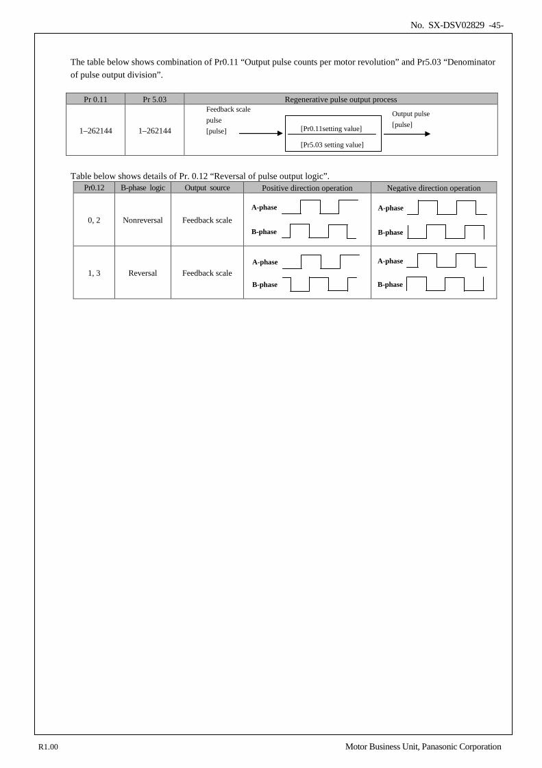
No. SX-DSV02829 -45-
The table below shows combination of Pr0.11 “Output pulse counts per motor revolution” and Pr5.03 “Denominator of pulse output division”.
Pr 0.11 Pr 5.03 Regenerative pulse output process
1–262144 1–262144
Table below shows details of Pr. 0.12 “Reversal of pulse output logic”.
Pr0.12 B-phase logic Output source Positive direction operation Negative direction operation
0, 2 Nonreversal Feedback scale
A-phase
B-phase
A-phase
B-phase
1, 3 Reversal Feedback scale
A-phase
B-phase
A-phase
B-phase
[Pr0.11setting value]
Feedback scale pulse [pulse]
Output pulse [pulse]
[Pr5.03 setting value]
R1.00 Motor Business Unit, Panasonic Corporation
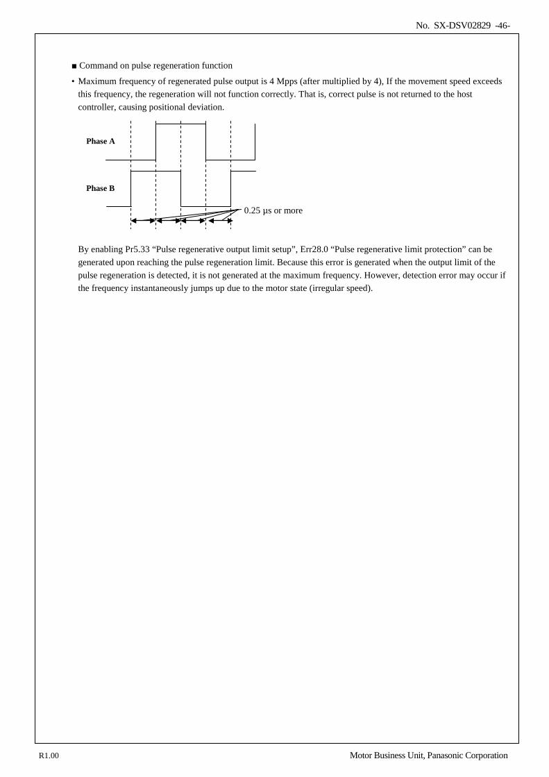
No. SX-DSV02829 -46-
Command on pulse regeneration function
• Maximum frequency of regenerated pulse output is 4 Mpps (after multiplied by 4), If the movement speed exceeds this frequency, the regeneration will not function correctly. That is, correct pulse is not returned to the host controller, causing positional deviation.
By enabling Pr5.33 “Pulse regenerative output limit setup”, Err28.0 “Pulse regenerative limit protection” can be generated upon reaching the pulse regeneration limit. Because this error is generated when the output limit of the pulse regeneration is detected, it is not generated at the maximum frequency. However, detection error may occur if the frequency instantaneously jumps up due to the motor state (irregular speed).
0.25 µs or more
Phase A
Phase B
R1.00 Motor Business Unit, Panasonic Corporation
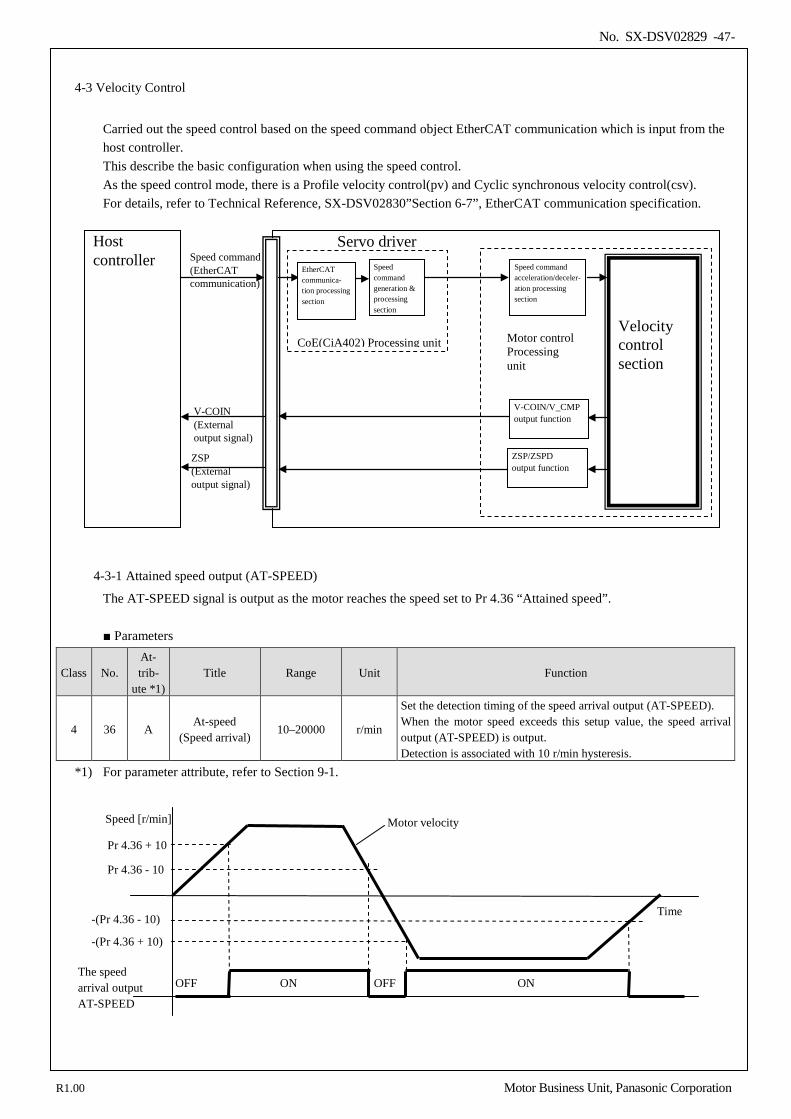
No. SX-DSV02829 -47-
4-3 Velocity Control
Carried out the speed control based on the speed command object EtherCAT communication which is input from the host controller. This describe the basic configuration when using the speed control. As the speed control mode, there is a Profile velocity control(pv) and Cyclic synchronous velocity control(csv). For details, refer to Technical Reference, SX-DSV02830”Section 6-7”, EtherCAT communication specification.
4-3-1 Attained speed output (AT-SPEED)
The AT-SPEED signal is output as the motor reaches the speed set to Pr 4.36 “Attained speed”.
Parameters
Class No. At- trib-
ute *1) Title Range Unit Function
4 36 A At-speed
(Speed arrival) 10–20000 r/min
Set the detection timing of the speed arrival output (AT-SPEED). When the motor speed exceeds this setup value, the speed arrival output (AT-SPEED) is output. Detection is associated with 10 r/min hysteresis.
*1) For parameter attribute, refer to Section 9-1.
Pr 4.36 + 10
Pr 4.36 - 10
-(Pr 4.36 + 10)
-(Pr 4.36 - 10)
The speed arrival output AT-SPEED
OFF ON ON OFF
Time
Motor velocity Speed [r/min]
Host controller
Servo driver Speed command acceleration/deceler-ation processing section
Velocity control section
Speed command (EtherCAT communication)
Speed command generation & processing section
EtherCAT communica- tion processing section
V-COIN/V_CMP output function
V-COIN (External output signal)
ZSP/ZSPD output function
ZSP (External output signal)
CoE(CiA402) Processing unit
Motor control Processing unit
R1.00 Motor Business Unit, Panasonic Corporation
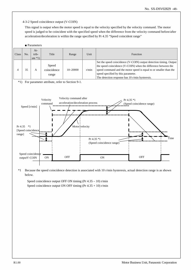
No. SX-DSV02829 -48-
4-3-2 Speed coincidence output (V-COIN)
This signal is output when the motor speed is equal to the velocity specified by the velocity command. The motor speed is judged to be coincident with the specified speed when the difference from the velocity command before/after acceleration/deceleration is within the range specified by Pr 4.35 “Speed coincident range”
Parameters
Class No. At- trib-
ute *1) Title Range Unit Function
4 35 A Speed
coincidence range
10–20000 r/min
Set the speed coincidence (V-COIN) output detection timing. Output the speed coincidence (V-COIN) when the difference between the speed command and the motor speed is equal to or smaller than the speed specified by this parameter. The detection response has 10 r/min hysteresis.
*1) For parameter attribute, refer to Section 9-1.
*1 Because the speed coincidence detection is associated with 10 r/min hysteresis, actual detection range is as shown
below.
Speed coincidence output OFF ON timing (Pr 4.35 – 10) r/min Speed coincidence output ON OFF timing (Pr 4.35 + 10) r/min
Speed coincidence outputV-COIN ON ON OFF
Speed [r/min]
OFF
Motor velocity Pr 4.35 *1 [Speed coincidence range]
Pr 4.35 *1 (Speed coincidence range)
Velocity command
Pr 4.35 *1 (Speed coincidence range)
Velocity command after acceleration/deceleration process
Time
R1.00 Motor Business Unit, Panasonic Corporation
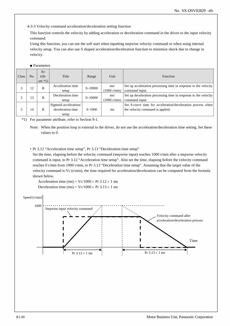
No. SX-DSV02829 -49-
4-3-3 Velocity command acceleration/deceleration setting function
This function controls the velocity by adding acceleration or deceleration command in the driver to the input velocity command. Using this function, you can use the soft start when inputting stepwise velocity command or when using internal velocity setup. You can also use S shaped acceleration/deceleration function to minimize shock due to change in velocity.
Parameters
Class No. At- trib-
ute *1) Title Range Unit Function
3 12 B Acceleration time
setup 0–10000
ms/ (1000 r/min)
Set up acceleration processing time in response to the velocity command input.
3 13 B Deceleration time
setup 0–10000
ms/ (1000 r/min)
Set up deceleration processing time in response to the velocity command input.
3 14 B Sigmoid acceleration/
deceleration time setup
0–1000 ms Set S-curve time for acceleration/deceleration process when the velocity command is applied.
*1) For parameter attribute, refer to Section 9-1.
Note: When the position loop is external to the driver, do not use the acceleration/deceleration time setting. Set these values to 0.
• Pr 3.12 “Acceleration time setup”, Pr 3.13 “Deceleration time setup” Set the time, elapsing before the velocity command (stepwise input) reaches 1000 r/min after a stepwise velocity command is input, to Pr 3.12 “Acceleration time setup”. Also set the time, elapsing before the velocity command reaches 0 r/min from 1000 r/min, to Pr 3.13 “Deceleration time setup”. Assuming that the target value of the velocity command is Vc (r/min), the time required for acceleration/deceleration can be computed from the formula shown below.
Acceleration time (ms) = Vc/1000 × Pr 3.12 × 1 ms Deceleration time (ms) = Vc/1000 × Pr 3.13 × 1 ms
Time
Pr 3.12 × 1 ms Pr 3.13 × 1 ms
Stepwise input velocity command
Velocity command after acceleration/deceleration process
Speed [r/min]
1000
R1.00 Motor Business Unit, Panasonic Corporation
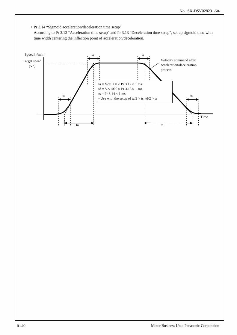
No. SX-DSV02829 -50-
• Pr 3.14 “Sigmoid acceleration/deceleration time setup”
According to Pr 3.12 “Acceleration time setup” and Pr 3.13 “Deceleration time setup”, set up sigmoid time with time width centering the inflection point of acceleration/deceleration.
Target speed (Vc)
ta
Velocity command after acceleration/deceleration process
Speed [r/min]
Time
td
ts ts
ts ts
ta = Vc/1000 × Pr 3.12 × 1 ms td = Vc/1000 × Pr 3.13 × 1 ms ts = Pr 3.14 × 1 ms • Use with the setup of ta/2 > ts, td/2 > ts
R1.00 Motor Business Unit, Panasonic Corporation
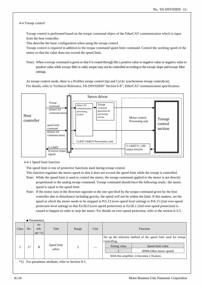
No. SX-DSV02829 -51-
4-4 Toruqe control
Toruqe control is performed based on the torque command object of the EtherCAT communication which is input from the host controller. This describe the basic configuration when using the toruqe control. Toruqe control is required in addition to the torque command speed limit command. Control the working speed of the motor so that the value does not exceed the speed limit. Note) When a toruqe command is given so that 0 is routed through like a positive value to negative value or negative value to
positive value while toruqe filter is valid, torque may not be controlled according to the toruqe slope and toruqe filter settings.
As toruqe control mode, there is a Profiles toruqe control (tq) and Cyclic synchronous toruqe control(cst). For details, refer to Technical Reference, SX-DSV02830” Section 6-8”, EtherCAT communication specification.
4-4-1 Speed limit function
The speed limit is one of protective functions used during toruqe control. This function regulates the motor speed so that it does not exceed the speed limit while the toruqe is controlled. Note: While the speed limit is used to control the motor, the toruqe command applied to the motor is not directly
proportional to the analog toruqe command. Toruqe command should have the following result.: the motor speed is equal to the speed limit.
Note: If the motor runs in the direction opposite to the one specified by the torque command given by the host controller due to disturbance including gravity, the speed will not be within the limit. If this matters, set the speed at which the motor needs to be stopped in Pr5.13 (over-speed level setting) or Pr6.15 (2nd over-speed protection level setting) so that Err26.0 (over-speed protection) or Err26.1 (2nd over-speed protection) is caused to happen in order to stop the motor. For details on over-speed protection, refer to the section 6-3-5.
Parameters
Class No. At- trib-
ute *1) Title Range Unit Function
3 17 B Speed limit
select 2 —
Set up the selection method of the speed limit used for toruqe controlling.
Setting value Speed limit value 2 6080h (Max motor speed)
With this amplifier, it becomes 2 fixation. *1) For parameter attribute, refer to Section 9-1.
Host controller
Servo driver
Toruqe control section
Toruqe command (EtherCAT communication)
Toruqe command generation & processing section
EtherCAT communication processing section
V-LIMIT/V_LIM output function
V-LIMIT (External output signal)
speed limit command (EtherCAT communication)
CoE(CiA402) Processing unit
Motor control Processing unit
R1.00 Motor Business Unit, Panasonic Corporation
No. SX-DSV02829 -52-
4-5 Setting regenerative resistor
The table describes setup of regenerative resistor. For details of regenerative resistor specification, refer to Technical Reference SX-DSV02828.
Parameters
Class No. At- trib-
ute *1) Title Range Unit Function
0 16 C External
Regenerative resistor setup
0–3 —
With this parameter, you can select either to use the built-in regenerative resistor of the driver, or to separate this built-in regenerative resistor and externally install the regenerative resistor.
0: Use the built-in resistor and activate regenerative over-load protection.
1: Use the external resistor and activate regenerative over-load protection.
2: Use the external resistor but do not activate regenerative over-load protection.
3: Do not use regenerative resistor. (Do not use over-load protection.)
0 17 C
Selection of load factor of external
regenerative resistor
0–4 —
When selecting the external regenerative resistor (Pr 0.16 = 1, 2), select the computing method of load factor of regenerative resistor.
0: Regenerative load factor is 100% when duty factor of external regenerative resistor is 10%. (Compatible with A4N series)
1–4: For manufacturer’s use (do not setup) *1) For parameter attribute, refer to Section 9-1.
R1.00 Motor Business Unit, Panasonic Corporation
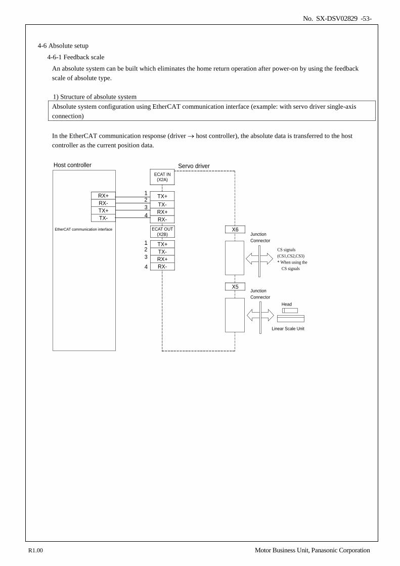
No. SX-DSV02829 -53-
4-6 Absolute setup
4-6-1 Feedback scale
An absolute system can be built which eliminates the home return operation after power-on by using the feedback scale of absolute type.
1) Structure of absolute system Absolute system configuration using EtherCAT communication interface (example: with servo driver single-axis connection)
In the EtherCAT communication response (driver → host controller), the absolute data is transferred to the host controller as the current position data.
X6
Host controller Servo driver
EtherCAT communication interface
1 2
Junction Connector
ECAT IN (X2A)
TX+ TX- RX+ RX-
3 4
RX+ RX- TX+ TX-
1 2
ECAT OUT (X2B)
TX+ TX- RX+ RX-
3
4
X5
Junction Connector
Linear Scale Unit
Head
CS signals (CS1,CS2,CS3) * When using the CS signals
R1.00 Motor Business Unit, Panasonic Corporation
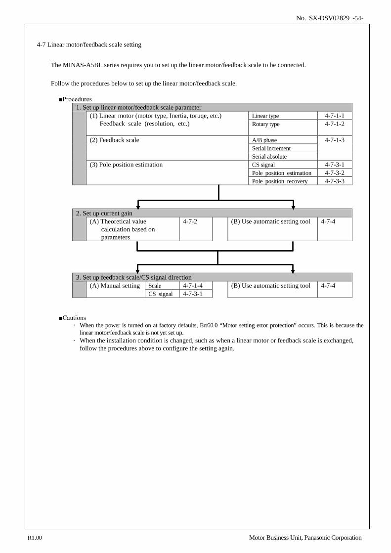
No. SX-DSV02829 -54-
4-7 Linear motor/feedback scale setting
The MINAS-A5BL series requires you to set up the linear motor/feedback scale to be connected. Follow the procedures below to set up the linear motor/feedback scale.
Procedures 1. Set up linear motor/feedback scale parameter (1) Linear motor (motor type, Inertia, toruqe, etc.)
Feedback scale (resolution, etc.) Linear type 4-7-1-1 Rotary type 4-7-1-2
(2) Feedback scale A/B phase 4-7-1-3
Serial increment Serial absolute
(3) Pole position estimation CS signal 4-7-3-1 Pole position estimation 4-7-3-2 Pole position recovery 4-7-3-3
2. Set up current gain (A) Theoretical value
calculation based on parameters
4-7-2 (B) Use automatic setting tool 4-7-4
3. Set up feedback scale/CS signal direction (A) Manual setting Scale 4-7-1-4 (B) Use automatic setting tool 4-7-4
CS signal 4-7-3-1
Cautions When the power is turned on at factory defaults, Err60.0 “Motor setting error protection” occurs. This is because the
linear motor/feedback scale is not yet set up. When the installation condition is changed, such as when a linear motor or feedback scale is exchanged,
follow the procedures above to configure the setting again.
R1.00 Motor Business Unit, Panasonic Corporation
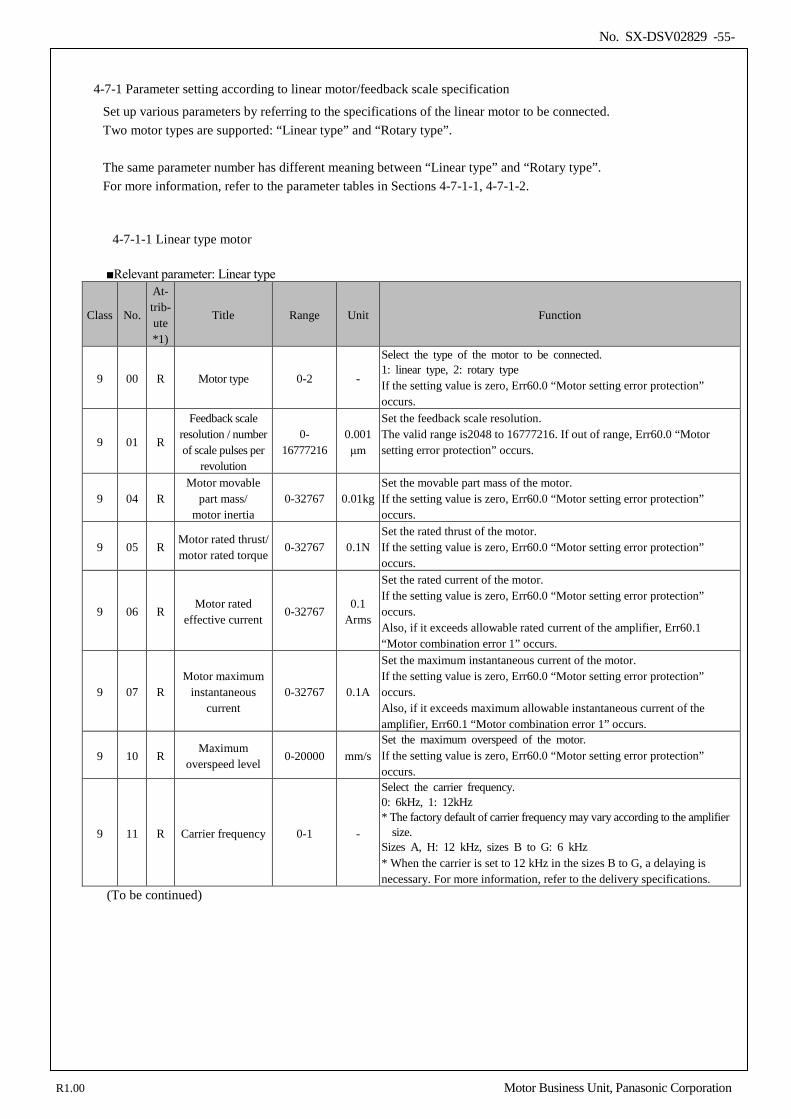
No. SX-DSV02829 -55-
4-7-1 Parameter setting according to linear motor/feedback scale specification
Set up various parameters by referring to the specifications of the linear motor to be connected. Two motor types are supported: “Linear type” and “Rotary type”. The same parameter number has different meaning between “Linear type” and “Rotary type”. For more information, refer to the parameter tables in Sections 4-7-1-1, 4-7-1-2.
4-7-1-1 Linear type motor
Relevant parameter: Linear type
Class No.
At- trib- ute *1)
Title Range Unit Function
9 00 R Motor type 0-2 -
Select the type of the motor to be connected. 1: linear type, 2: rotary type If the setting value is zero, Err60.0 “Motor setting error protection” occurs.
9 01 R
Feedback scale resolution / number of scale pulses per
revolution
0- 16777216
0.001 μm
Set the feedback scale resolution. The valid range is2048 to 16777216. If out of range, Err60.0 “Motor setting error protection” occurs.
9 04 R Motor movable
part mass/ motor inertia
0-32767 0.01kg Set the movable part mass of the motor. If the setting value is zero, Err60.0 “Motor setting error protection” occurs.
9 05 R Motor rated thrust/ motor rated torque
0-32767 0.1N Set the rated thrust of the motor. If the setting value is zero, Err60.0 “Motor setting error protection” occurs.
9 06 R Motor rated
effective current 0-32767
0.1 Arms
Set the rated current of the motor. If the setting value is zero, Err60.0 “Motor setting error protection” occurs. Also, if it exceeds allowable rated current of the amplifier, Err60.1 “Motor combination error 1” occurs.
9 07 R Motor maximum
instantaneous current
0-32767 0.1A
Set the maximum instantaneous current of the motor. If the setting value is zero, Err60.0 “Motor setting error protection” occurs. Also, if it exceeds maximum allowable instantaneous current of the amplifier, Err60.1 “Motor combination error 1” occurs.
9 10 R Maximum
overspeed level 0-20000 mm/s
Set the maximum overspeed of the motor. If the setting value is zero, Err60.0 “Motor setting error protection” occurs.
9 11 R Carrier frequency 0-1 -
Select the carrier frequency. 0: 6kHz, 1: 12kHz * The factory default of carrier frequency may vary according to the amplifier
size. Sizes A, H: 12 kHz, sizes B to G: 6 kHz * When the carrier is set to 12 kHz in the sizes B to G, a delaying is necessary. For more information, refer to the delivery specifications.
(To be continued)
R1.00 Motor Business Unit, Panasonic Corporation
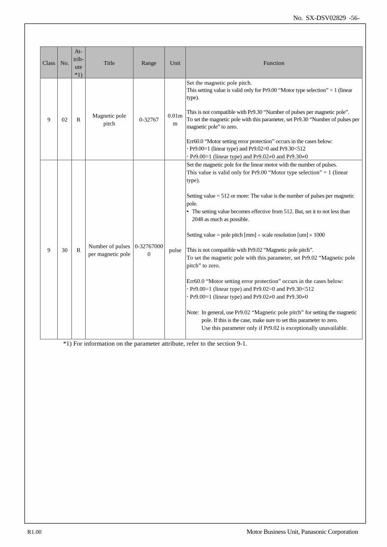
No. SX-DSV02829 -56-
Class No.
At- trib- ute *1)
Title Range Unit Function
9 02 R Magnetic pole
pitch 0-32767
0.01mm
Set the magnetic pole pitch. This setting value is valid only for Pr9.00 “Motor type selection” = 1 (linear type). This is not compatible with Pr9.30 “Number of pulses per magnetic pole”. To set the magnetic pole with this parameter, set Pr9.30 “Number of pulses per magnetic pole” to zero. Err60.0 “Motor setting error protection” occurs in the cases below: Pr9.00=1 (linear type) and Pr9.02=0 and Pr9.30<512 Pr9.00=1 (linear type) and Pr9.02≠0 and Pr9.30≠0
9 30 R Number of pulses per magnetic pole
0-327670000
pulse
Set the magnetic pole for the linear motor with the number of pulses. This value is valid only for Pr9.00 “Motor type selection” = 1 (linear type). Setting value = 512 or more: The value is the number of pulses per magnetic pole. The setting value becomes effective from 512. But, set it to not less than
2048 as much as possible. Setting value = pole pitch [mm] ÷ scale resolution [um] × 1000 This is not compatible with Pr9.02 “Magnetic pole pitch”. To set the magnetic pole with this parameter, set Pr9.02 “Magnetic pole pitch” to zero. Err60.0 “Motor setting error protection” occurs in the cases below: Pr9.00=1 (linear type) and Pr9.02=0 and Pr9.30<512 Pr9.00=1 (linear type) and Pr9.02≠0 and Pr9.30≠0 Note: In general, use Pr9.02 “Magnetic pole pitch” for setting the magnetic
pole. If this is the case, make sure to set this parameter to zero. Use this parameter only if Pr9.02 is exceptionally unavailable.
*1) For information on the parameter attribute, refer to the section 9-1.
R1.00 Motor Business Unit, Panasonic Corporation
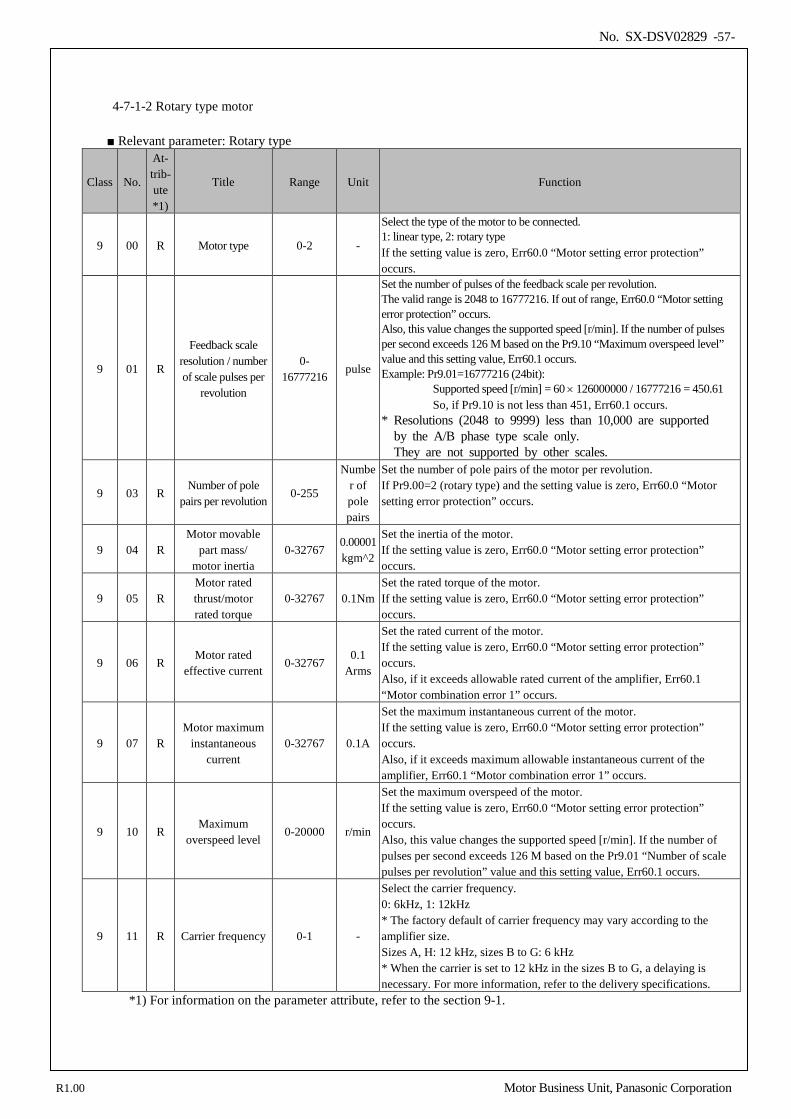
No. SX-DSV02829 -57-
4-7-1-2 Rotary type motor
Relevant parameter: Rotary type
Class No.
At- trib- ute *1)
Title Range Unit Function
9 00 R Motor type 0-2 -
Select the type of the motor to be connected. 1: linear type, 2: rotary type If the setting value is zero, Err60.0 “Motor setting error protection” occurs.
9 01 R
Feedback scale resolution / number of scale pulses per
revolution
0- 16777216
pulse
Set the number of pulses of the feedback scale per revolution. The valid range is 2048 to 16777216. If out of range, Err60.0 “Motor setting error protection” occurs. Also, this value changes the supported speed [r/min]. If the number of pulses per second exceeds 126 M based on the Pr9.10 “Maximum overspeed level” value and this setting value, Err60.1 occurs. Example: Pr9.01=16777216 (24bit):
Supported speed [r/min] = 60 × 126000000 / 16777216 = 450.61 So, if Pr9.10 is not less than 451, Err60.1 occurs.
* Resolutions (2048 to 9999) less than 10,000 are supported by the A/B phase type scale only. They are not supported by other scales.
9 03 R Number of pole
pairs per revolution 0-255
Number of pole pairs
Set the number of pole pairs of the motor per revolution. If Pr9.00=2 (rotary type) and the setting value is zero, Err60.0 “Motor setting error protection” occurs.
9 04 R Motor movable
part mass/ motor inertia
0-32767 0.00001 kgm^2
Set the inertia of the motor. If the setting value is zero, Err60.0 “Motor setting error protection” occurs.
9 05 R Motor rated thrust/motor rated torque
0-32767 0.1Nm Set the rated torque of the motor. If the setting value is zero, Err60.0 “Motor setting error protection” occurs.
9 06 R Motor rated
effective current 0-32767
0.1 Arms
Set the rated current of the motor. If the setting value is zero, Err60.0 “Motor setting error protection” occurs. Also, if it exceeds allowable rated current of the amplifier, Err60.1 “Motor combination error 1” occurs.
9 07 R Motor maximum
instantaneous current
0-32767 0.1A
Set the maximum instantaneous current of the motor. If the setting value is zero, Err60.0 “Motor setting error protection” occurs. Also, if it exceeds maximum allowable instantaneous current of the amplifier, Err60.1 “Motor combination error 1” occurs.
9 10 R Maximum
overspeed level 0-20000 r/min
Set the maximum overspeed of the motor. If the setting value is zero, Err60.0 “Motor setting error protection” occurs. Also, this value changes the supported speed [r/min]. If the number of pulses per second exceeds 126 M based on the Pr9.01 “Number of scale pulses per revolution” value and this setting value, Err60.1 occurs.
9 11 R Carrier frequency 0-1 -
Select the carrier frequency. 0: 6kHz, 1: 12kHz * The factory default of carrier frequency may vary according to the amplifier size. Sizes A, H: 12 kHz, sizes B to G: 6 kHz * When the carrier is set to 12 kHz in the sizes B to G, a delaying is necessary. For more information, refer to the delivery specifications.
*1) For information on the parameter attribute, refer to the section 9-1.
R1.00 Motor Business Unit, Panasonic Corporation
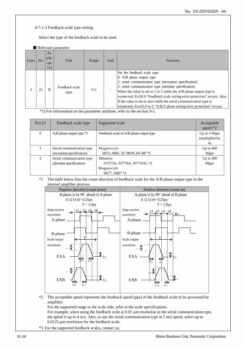
No. SX-DSV02829 -58-
4-7-1-3 Feedback scale type setting Select the type of the feedback scale to be used.
Relevant parameter
Class No.
At- trib- ute *1)
Title Range Unit Function
3 23 R Feedback scale
type 0-2 -
Set the feedback scale type. 0: A/B phase output type 1: serial communication type (increment specification) 2: serial communication type (absolute specification) When the value is set to 1 or 2 while the A/B phase output type is connected, Err50.0 “Feedback scale wiring error protection” occurs. Also, if the value is set to zero while the serial communication type is connected, Errs55.0 to 2 “A/B/Z phase wiring error protection” occurs.
*1) For information on the parameter attribute, refer to the section 9-1.
Pr3.23 Feedback scale type Supported scale Acceptable speed *2
0 A/B phase output type *1 Feedback scale of A/B phase output type Up to 4 Mpps (multiplied by
4) 1 Serial communication type
(increment specification) Magnescale
SR75, SR85, SL700/PL101-RP *3 Up to 400
Mpps 2 Serial communication type
(absolute specification) Mitutoyo
AT573A, ST770A, ST770AL *3 Magnescale
SR77, SR87 *3
Up to 400 Mpps
*1 The table below lists the count direction of feedback scale for the A/B phase output type in the internal amplifier process.
Negative direction (count down) Positive direction (count up) B-phase is by 90° ahead of A-phase
t1 t2 t3 t4> 0.25µs T > 1.0µs
Amp receive waveform Scale output waveform
A-phase is by 90° ahead of B-phase t1 t2 t3 t4> 0.25µs
T > 1.0µs Amp receive waveform Scale output
waveform
*2 The acceptable speed represents the feedback speed [pps] of the feedback scale to be processed by amplifier. For the supported range in the scale side, refer to the scale specifications. For example, when using the feedback scale at 0.01 µm resolution in the serial communication type, the speed is up to 4 m/s. Also, to use the serial communication type at 5 m/s speed, select up to 0.0125 µm resolution for the feedback scale.
*3 For the supported feedback scales, contact us.
T
t1
T
A-phase
B-phase
EXA
EXB U
U UL
UL
t+L t-L EXA
U UL
t+L t-L
EXB UH
UL t+L t-L
t4 t3 t2
t-L t+L
t4 t3 t2 t1 A-phase
B-phase
R1.00 Motor Business Unit, Panasonic Corporation
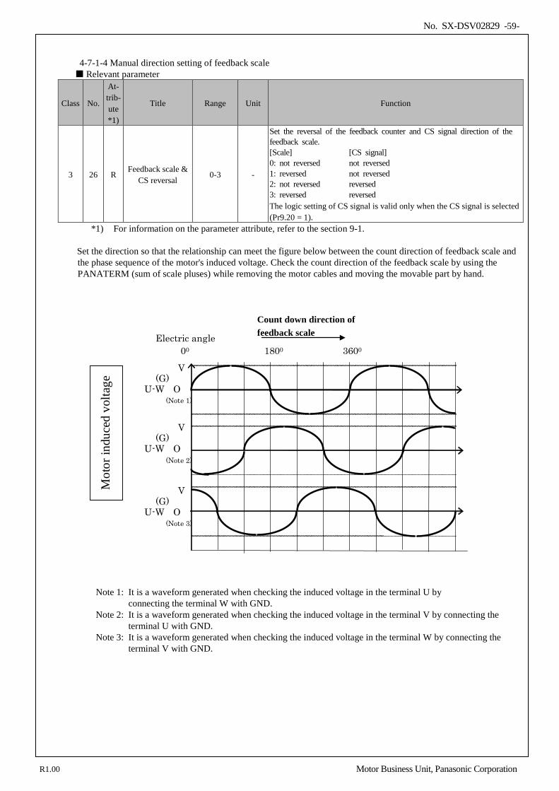
No. SX-DSV02829 -59-
4-7-1-4 Manual direction setting of feedback scale Relevant parameter
Class No.
At- trib- ute *1)
Title Range Unit Function
3 26 R Feedback scale &
CS reversal 0-3 -
Set the reversal of the feedback counter and CS signal direction of the feedback scale. [Scale] [CS signal] 0: not reversed not reversed 1: reversed not reversed 2: not reversed reversed 3: reversed reversed The logic setting of CS signal is valid only when the CS signal is selected (Pr9.20 = 1).
*1) For information on the parameter attribute, refer to the section 9-1.
Set the direction so that the relationship can meet the figure below between the count direction of feedback scale and the phase sequence of the motor's induced voltage. Check the count direction of the feedback scale by using the PANATERM (sum of scale pluses) while removing the motor cables and moving the movable part by hand.
00 1800 3600
V (G)
U-W O (Note 1)
V (G)
U-W O (Note 3)
V (G)
U-W O (Note 2)
Electric angle
Mot
or in
duce
d vo
ltage
Note 1: It is a waveform generated when checking the induced voltage in the terminal U by
connecting the terminal W with GND. Note 2: It is a waveform generated when checking the induced voltage in the terminal V by connecting the
terminal U with GND. Note 3: It is a waveform generated when checking the induced voltage in the terminal W by connecting the
terminal V with GND.
Count down direction of feedback scale
R1.00 Motor Business Unit, Panasonic Corporation
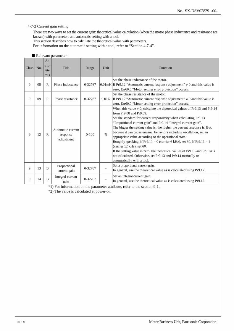
No. SX-DSV02829 -60-
4-7-2 Current gain setting There are two ways to set the current gain: theoretical value calculation (when the motor phase inductance and resistance are known) with parameters and automatic setting with a tool. This section describes how to calculate the theoretical value with parameters. For information on the automatic setting with a tool, refer to “Section 4-7-4”.
Relevant parameter
Class No.
At- trib- ute *1)
Title Range Unit Function
9 08 R Phase inductance 0-32767 0.01mH Set the phase inductance of the motor. If Pr9.12 “Automatic current response adjustment” ≠ 0 and this value is zero, Err60.0 “Motor setting error protection” occurs.
9 09 R Phase resistance 0-32767 0.01Ω Set the phase resistance of the motor. If Pr9.12 “Automatic current response adjustment” ≠ 0 and this value is zero, Err60.0 “Motor setting error protection” occurs.
9 12 R Automatic current
response adjustment
0-100 %
When this value ≠ 0, calculate the theoretical values of Pr9.13 and Pr9.14 from Pr9.08 and Pr9.09. Set the standard for current responsivity when calculating Pr9.13 “Proportional current gain” and Pr9.14 “Integral current gain”. The bigger the setting value is, the higher the current response is. But, because it can cause unusual behaviors including oscillation, set an appropriate value according to the operational state. Roughly speaking, if Pr9.11 = 0 (carrier 6 kHz), set 30. If Pr9.11 = 1 (carrier 12 kHz), set 60. If the setting value is zero, the theoretical values of Pr9.13 and Pr9.14 is not calculated. Otherwise, set Pr9.13 and Pr9.14 manually or automatically with a tool.
9 13 B Proportional current gain
0-32767 - Set a proportional current gain. In general, use the theoretical value as is calculated using Pr9.12.
9 14 B Integral current
gain 0-32767 -
Set an integral current gain. In general, use the theoretical value as is calculated using Pr9.12.
*1) For information on the parameter attribute, refer to the section 9-1. *2) The value is calculated at power-on.
R1.00 Motor Business Unit, Panasonic Corporation
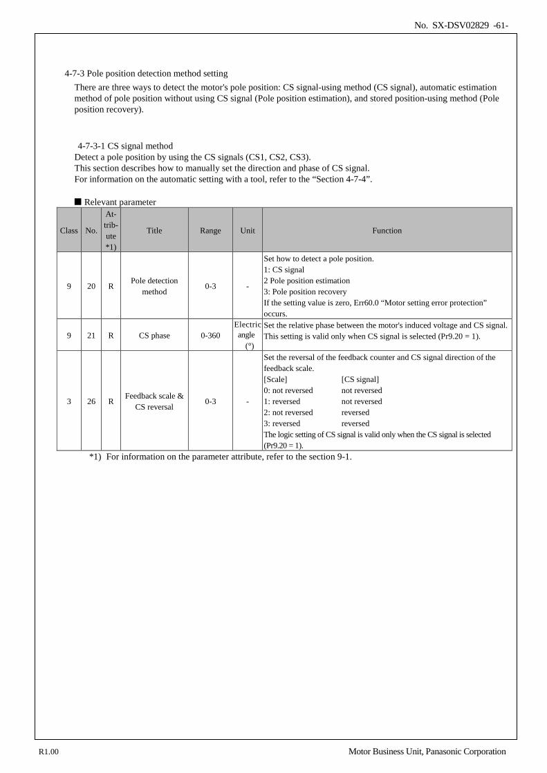
No. SX-DSV02829 -61-
4-7-3 Pole position detection method setting There are three ways to detect the motor's pole position: CS signal-using method (CS signal), automatic estimation method of pole position without using CS signal (Pole position estimation), and stored position-using method (Pole position recovery).
4-7-3-1 CS signal method Detect a pole position by using the CS signals (CS1, CS2, CS3). This section describes how to manually set the direction and phase of CS signal. For information on the automatic setting with a tool, refer to the “Section 4-7-4”.
Relevant parameter
Class No.
At- trib- ute *1)
Title Range Unit Function
9 20 R Pole detection
method 0-3 -
Set how to detect a pole position. 1: CS signal 2 Pole position estimation 3: Pole position recovery If the setting value is zero, Err60.0 “Motor setting error protection” occurs.
9 21 R CS phase 0-360 Electric angle
(°)
Set the relative phase between the motor's induced voltage and CS signal. This setting is valid only when CS signal is selected (Pr9.20 = 1).
3 26 R Feedback scale &
CS reversal 0-3 -
Set the reversal of the feedback counter and CS signal direction of the feedback scale. [Scale] [CS signal] 0: not reversed not reversed 1: reversed not reversed 2: not reversed reversed 3: reversed reversed The logic setting of CS signal is valid only when the CS signal is selected (Pr9.20 = 1).
*1) For information on the parameter attribute, refer to the section 9-1.
R1.00 Motor Business Unit, Panasonic Corporation
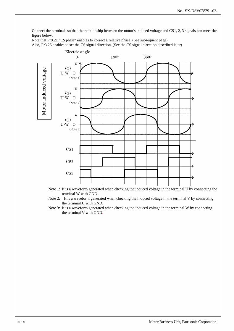
No. SX-DSV02829 -62-
Connect the terminals so that the relationship between the motor's induced voltage and CS1, 2, 3 signals can meet the figure below. Note that Pr9.21 “CS phase” enables to correct a relative phase. (See subsequent page) Also, Pr3.26 enables to set the CS signal direction. (See the CS signal direction described later)
00 1800 3600
V (G)
U-W O (Note 1)
V (G)
U-W O (Note 3)
V (G)
U-W O (Note 2)
Electric angle
Mot
or in
duce
d vo
ltage
CS1
CS2
CS3
Note 1: It is a waveform generated when checking the induced voltage in the terminal U by connecting the
terminal W with GND. Note 2: It is a waveform generated when checking the induced voltage in the terminal V by connecting
the terminal U with GND. Note 3: It is a waveform generated when checking the induced voltage in the terminal W by connecting
the terminal V with GND.
R1.00 Motor Business Unit, Panasonic Corporation
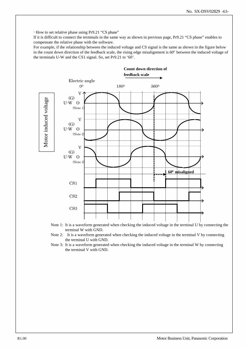
No. SX-DSV02829 -63-
How to set relative phase using Pr9.21 “CS phase” If it is difficult to connect the terminals in the same way as shown in previous page, Pr9.21 “CS phase” enables to compensate the relative phase with the software. For example, if the relationship between the induced voltage and CS signal is the same as shown in the figure below in the count down direction of the feedback scale, the rising edge misalignment is 60° between the induced voltage of the terminals U-W and the CS1 signal. So, set Pr9.21 to ‘60’.
00 1800 3600 V
(G) U-W O
(Note 1)
V (G)
U-W O (Note 3)
V (G)
U-W O (Note 2)
Electric angle
Mot
or in
duce
d vo
ltage
CS1
CS2
CS3
60° misaligned
Note 1: It is a waveform generated when checking the induced voltage in the terminal U by connecting the
terminal W with GND. Note 2: It is a waveform generated when checking the induced voltage in the terminal V by connecting
the terminal U with GND. Note 3: It is a waveform generated when checking the induced voltage in the terminal W by connecting
the terminal V with GND.
Count down direction of feedback scale
R1.00 Motor Business Unit, Panasonic Corporation
No. SX-DSV02829 -64-
How to set the CS signal direction by using Pr3.26 “Feedback scale & CS reversal” There are two types of wiring patterns among CS1, CS2, and CS3 as shown in the figure below. In the figure above, the wiring among CS1, CS2, and CS3 is correct for the induced voltage, so set the CS signal direction to “not reversed” using Pr3.26. On the contrary, in the figure below, the wiring between CS2 and CS3 is the reverse of the figure above, so set the CS signal direction to “reversed” by using Pr3.26. The “reversed” CS direction exchanges CS2 and CS3 on the inside of the servo amplifier, so the motor works properly.
00 1800 3600 V
(G) U-W O
(Note 1)
V (G)
U-W O (Note 3)
V (G)
U-W O (Note 2)
Electric angle
Mot
or in
duce
d vo
ltage
CS1
CS2
CS3
CS1
CS2
CS3
CS direction: not reversed
CS direction: reversed
Note 1: It is a waveform generated when checking the induced voltage in the terminal U by connecting the terminal W with GND.
Note 2: It is a waveform generated when checking the induced voltage in the terminal V by connecting the terminal U with GND.
Note 3: It is a waveform generated when checking the induced voltage in the terminal W by connecting the terminal V with GND.
R1.00 Motor Business Unit, Panasonic Corporation
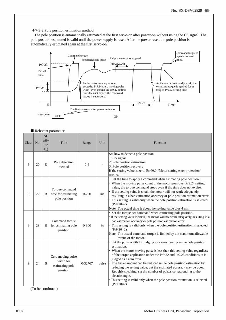
No. SX-DSV02829 -65-
4-7-3-2 Pole position estimation method The pole position is automatically estimated at the first servo-on after power-on without using the CS signal. The
pole position estimated is valid until the power supply is reset. After the power reset, the pole position is automatically estimated again at the first servo-on.
Relevant parameter
Class No.
At- trib- ute *1)
Title Range Unit Function
9 20 R Pole detection
method 0-3 -
Set how to detect a pole position. 1: CS signal 2: Pole position estimation 3: Pole position recovery If the setting value is zero, Err60.0 “Motor setting error protection” occurs.
9 22 B Torque command
time for estimating pole position
0-200 ms
Set the time to apply a command when estimating pole position. When the moving pulse count of the motor goes over Pr9.24 setting
value, the torque command stops even if the time does not expire. If the setting value is small, the motor will not work adequately,
resulting in a bad estimation accuracy or pole position estimation error. This setting is valid only when the pole position estimation is selected
(Pr9.20=2). Note: The actual time is about the setting value plus 4 ms.
9 23 B Command torque
for estimating pole position
0-300 %
Set the torque per command when estimating pole position. If the setting value is small, the motor will not work adequately, resulting in a
bad estimation accuracy or pole position estimation error. This setting is valid only when the pole position estimation is selected
(Pr9.20=2). Note: The actual command torque is limited by the maximum allowable
torque of the motor.
9 24 B
Zero moving pulse width for
estimating pole position
0-32767 pulse
Set the pulse width for judging as a zero moving in the pole position estimation. When the motor moving pulse is less than this setting value regardless
of the torque application under the Pr9.22 and Pr9.23 conditions, it is judged as a zero travel. The travel amount can be reduced in the pole position estimation by
reducing the setting value, but the estimated accuracy may be poor. Roughly speaking, set the number of pulses corresponding to the electric angle. This setting is valid only when the pole position estimation is selected
(Pr9.20=2). (To be continued)
Time
Command torque Feedback scale pulse
0
Pr9.23
Pr9.24
Pr9.22
As the motor moving amount exceeded Pr9.24 (zero moving pulse width) even though the Pr9.22 setting time does not expire, the command torque is set to zero.
Judge the motor as stopped
(Pr9.25,9.26)
Pr9.28 Filter
As the motor does hardly work, the command torque is applied for as long as Pr9.22 setting time.
servo-on OFF ON
The first servo-on after power activation.
Command torque is repeated several times.
R1.00 Motor Business Unit, Panasonic Corporation
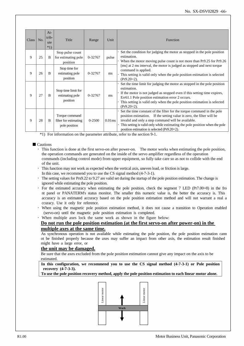
No. SX-DSV02829 -66-
Class No.
At- trib- ute *1)
Title Range Unit Function
9 25 B Stop pulse count
for estimating pole position
0-32767 pulse Set the condition for judging the motor as stopped in the pole position
estimation. When the motor moving pulse count is not more than Pr9.25 for Pr9.26
[ms] at 2 ms interval, the motor is judged as stopped and next torque command is applied. This setting is valid only when the pole position estimation is selected
(Pr9.20=2). 9 26 B
Stop time for estimating pole
position 0-32767 ms
9 27 B Stop time limit for
estimating pole position
0-32767 ms
Set the time limit for judging the motor as stopped in the pole position estimation. If the motor is not judged as stopped even if this setting time expires,
Err61.1 Pole position estimation error 2 occurs. This setting is valid only when the pole position estimation is selected
(Pr9.20=2).
9 28 B Torque command filter for estimating
pole position 0-2500 0.01ms
Set the time constant of the filter for the torque command in the pole position estimation. If the setting value is zero, the filter will be invalid and only a step command will be available. This setting is valid only while estimating the pole position when the pole
position estimation is selected (Pr9.20=2). *1) For information on the parameter attribute, refer to the section 9-1.
Cautions This function is done at the first servo-on after power-on. The motor works when estimating the pole position,
the operation commands are generated on the inside of the servo amplifier regardless of the operation commands (including control mode) from upper equipment, so fully take care so as not to collide with the end of the unit.
This function may not work as expected when the vertical axis, uneven load, or friction is large. In this case, we recommend you to use the CS signal method (4-7-3-1).
The setting values for Prs9.22 to 9.27 are valid set during the startup of the pole position estimation. The change is ignored while estimating the pole position.
For the estimated accuracy when estimating the pole position, check the segment 7 LED (Pr7.00=8) in the front panel or PANATERM's status monitor. The smaller this numeric value is, the better the accuracy is. This accuracy is an estimated accuracy based on the pole position estimation method and will not warrant a real accuracy. Use it only for reference.
When using the magnetic pole position estimation method, it does not cause a transition to Operation enabled (servo-on) until the magnetic pole position estimation is completed.
When multiple axes lock the same work as shown in the figure below: Do not run the pole position estimation (at the first servo-on after power-on) in the multiple axes at the same time. As synchronous operation is not available while estimating the pole position, the pole position estimation cannot be finished properly because the axes may suffer an impact from other axis, the estimation result finished might have a large error, or the unit may be damaged. Be sure that the axes excluded from the pole position estimation cannot give any impact on the axis to be estimated. In this configuration, we recommend you to use the CS signal method (4-7-3-1) or Pole position recovery (4-7-3-3). To use the pole position recovery method, apply the pole position estimation to each linear motor alone.
Work
Line
ar m
otor
Line
ar m
otor
R1.00 Motor Business Unit, Panasonic Corporation
No. SX-DSV02829 -67-
4-7-3-3 Pole position recovery method Once a pole position is estimated with the pole position estimation method (4-7-3-2), the pole position can be stored and the motor can be controlled by using the pole position even after the power reset. This recovery method can be supported only when the feedback scale of absolute type is used.
Relevant parameter Class No. Title Range Unit Function
9 20 Pole detection method 0-3 -
Set how to detect a pole position. 1: CS signal 2: Pole position estimation 3: Pole position recovery If the setting value is zero, Err60.0 “Motor setting error protection” occurs.
Procedures (1) Set Pr9.20=2 and make an pole position estimation (see 4-7-3-2)
The pole position estimation result is stored by the servo amplifier (2) Set Pr9.20=3 and turn the control power OFF and ON again
Cautions The estimation result of the pole position is stored in the amplifier. When the combination of the amplifier and linear
motor is changed (exchange of amplifier, linear motor, or feedback scale), the pole position may change, thereby disabling you to control the motor properly. In this case, because the amplifier cannot recognize the change, an alarm will not occur. When one of components above is exchanged at least, set Pr9.20=2 once. Then, estimate the poles position again and set Pr9.20=3.
When this method is selected while the pole position is not estimated at all or while the estimation result of the
pole position is cleared, Err61.2 “Magnetic pole position estimation error 3” occurs. The estimation result of the pole position is cleared when the detection method of pole position is not specified
(Pr9.20=0). However, EEPROM relevant alarms (Errs36.0 - 2, Errs37.0 - 2) are not cleared. Also, any alarm is not cleared when Err11.0 “Control power undervoltage protection” occurred.
When this method is selected while using the feedback scale of other than absolute type, Err61.2 “Pole position
estimation error 3” occurs.
R1.00 Motor Business Unit, Panasonic Corporation
No. SX-DSV02829 -68-
4-7-4 Automatic linear motor setting with tool The initial parameter (current gain, feedback scale direction, CS direction) for the combination with a linear motor can be automatically set by using the automatic setting tool (MotorAutoSetup).
Parameter changed by the automatic linear motor setting
The automatic linear motor setting updates the parameters below:
Class No.
At- trib- ute *1)
Title Range Unit Function
3 26 R Feedback scale &
CS reversal 0-3 -
Set the reversal of the feedback counter and CS signal direction of the feedback scale. [Scale] [CS signal] 0: not reversed not reversed 1: reversed not reversed 2: not reversed reversed 3: reversed reversed The logic setting of CS signal is valid only when the CS signal is selected (Pr9.20 = 1).
9 13 B Proportional current gain
0-32767 - Set a proportional current gain.
9 14 B Integral current
gain 0-32767 -
Set an integral current gain.
9 21 R CS phase 0–360 Electric angle
(°)
Set the relative phase between the motor's induced voltage and CS signal. This setting is valid only when CS signal is selected (Pr9.20 = 1).
*1) For information on the parameter attribute, refer to the section 9-1. To set Pr9.13 “Proportional current gain” and Pr9.14 “Integral current gain” by using the automatic linear motor
setting, set Pr9.12 “Automatic current response adjustment” to zero.
R1.00 Motor Business Unit, Panasonic Corporation
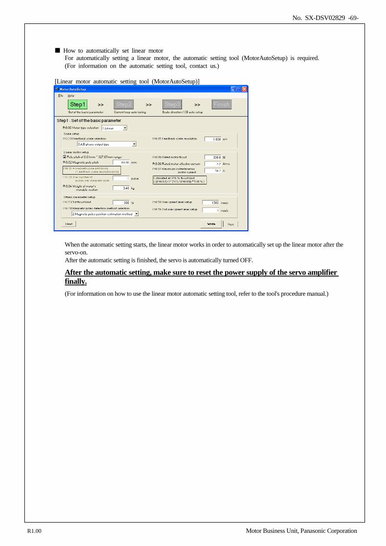
No. SX-DSV02829 -69-
How to automatically set linear motor For automatically setting a linear motor, the automatic setting tool (MotorAutoSetup) is required. (For information on the automatic setting tool, contact us.)
[Linear motor automatic setting tool (MotorAutoSetup)]
When the automatic setting starts, the linear motor works in order to automatically set up the linear motor after the servo-on. After the automatic setting is finished, the servo is automatically turned OFF.
After the automatic setting, make sure to reset the power supply of the servo amplifier finally. (For information on how to use the linear motor automatic setting tool, refer to the tool's procedure manual.)
R1.00 Motor Business Unit, Panasonic Corporation
No. SX-DSV02829 -70-
Cautions In the linear motor automatic setting, the motor may move up to two cycles of electric angle.
Secure the movable range in advance before the automatic setting. This function may not work as expected when the vertical axis, uneven load, or friction is large.
Also, the tool may not work properly when a load is mounted. If this is the case, run the tool with the linear motor alone by unmounting the load.
The tool may not work properly when the basic setting is not correct for the linear motor and scale. Set the data
properly by referring to “4-7-1 Parameter setting according to linear motor/feedback scale specification” in advance. If the network is established with the upper controller while automatically setting the linear motor, Err60.3 “Linear
motor automatic setting error protection” occurs and the tool is killed. If Pr9.20 “Pole detection method” = 2 (Pole position estimation), when the linear motor is automatically set while the
pole position estimation was finished, the pole position estimation becomes unfinished. The pole position will be estimated on next servo-on.
If the torque command is overshot while automatically setting the linear motor, Err60.3 “Linear motor automatic
setting error protection” occurs and the tool is killed. After the automatic setting is finished, make sure to reset the power supply of the servo amplifier and establish the
network with the upper controller. If it is tried to establish network with the upper controller without resetting the power supply of the servo amplifier, Err60.3 “Linear motor automatic setting error protection” occurs.
R1.00 Motor Business Unit, Panasonic Corporation
No. SX-DSV02829 -71-
5.Gain tuning/vibration suppressing function
5-1 Automatic adjusting function .............................................................................................................................. 72 5-1-1 Real-Time Auto Tuning ................................................................................................................................. 73 5-1-2 Adaptive filter ................................................................................................................................................ 81 5-1-3 Real-time Auto Tuning (2 Degrees of Freedom Control Mode Standard type) .......................................... 84
5-2 Manual adjusting function ................................................................................................................................... 92 5-2-1 Block diagram of position control mode ........................................................................................................ 93 5-2-2 Block diagram of velocity control mode ........................................................................................................ 94 5-2-3 Block diagram of torque control mode .......................................................................................................... 95 5-2-4 Gain Switching Function ............................................................................................................................... 96 5-2-5 Notch filter ................................................................................................................................................... 102 5-2-6 Damping Control.......................................................................................................................................... 104 5-2-7 Feed forward function .................................................................................................................................. 108 5-2-8 Instantaneous Velocity Observer function ................................................................................................... 110 5-2-9 Disturbance observer function ..................................................................................................................... 112 5-2-10 3rd gain switching function ........................................................................................................................ 114 5-2-11 Friction torque compensation ..................................................................................................................... 115 5-2-12 2-stage torque filter .................................................................................................................................... 117 5-2-13 Mode of 2 degrees of freedom control (Standerd type) ............................................................................. 118 5-2-14 Model type damping filter .......................................................................................................................... 121 5-2-15 Viscous friction compensating gain / Model type damping filter application parameter switching function .................................................................................................................................................................. 125
5
R1.00 Motor Business Unit, Panasonic Corporation
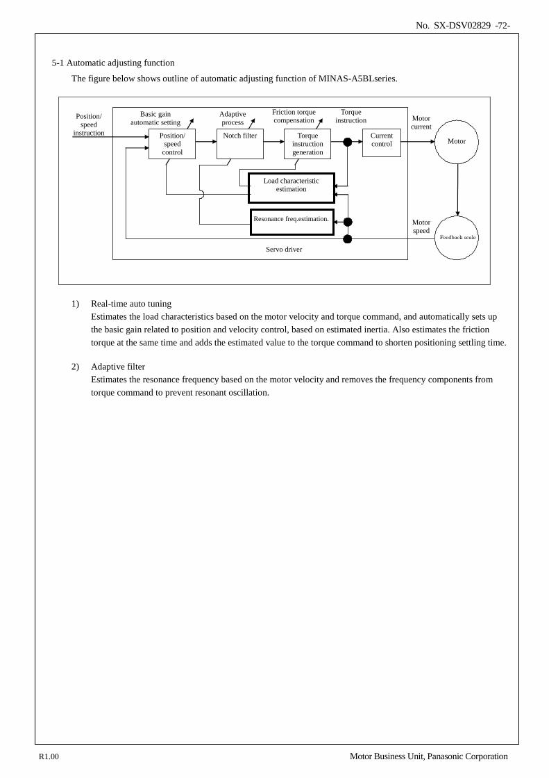
No. SX-DSV02829 -72-
5-1 Automatic adjusting function
The figure below shows outline of automatic adjusting function of MINAS-A5BLseries.
Current control
Position/ speed
instruction
Motor speed
Torque instruction
Basic gain automatic setting
Motor current
Motor
Feedback scale
Servo driver
Adaptive process
Load characteristic estimation
Friction torque compensation
Position/ speed
control
Notch filter Torque instruction generation
Resonance freq.estimation.
1) Real-time auto tuning Estimates the load characteristics based on the motor velocity and torque command, and automatically sets up the basic gain related to position and velocity control, based on estimated inertia. Also estimates the friction torque at the same time and adds the estimated value to the torque command to shorten positioning settling time.
2) Adaptive filter
Estimates the resonance frequency based on the motor velocity and removes the frequency components from torque command to prevent resonant oscillation.
R1.00 Motor Business Unit, Panasonic Corporation
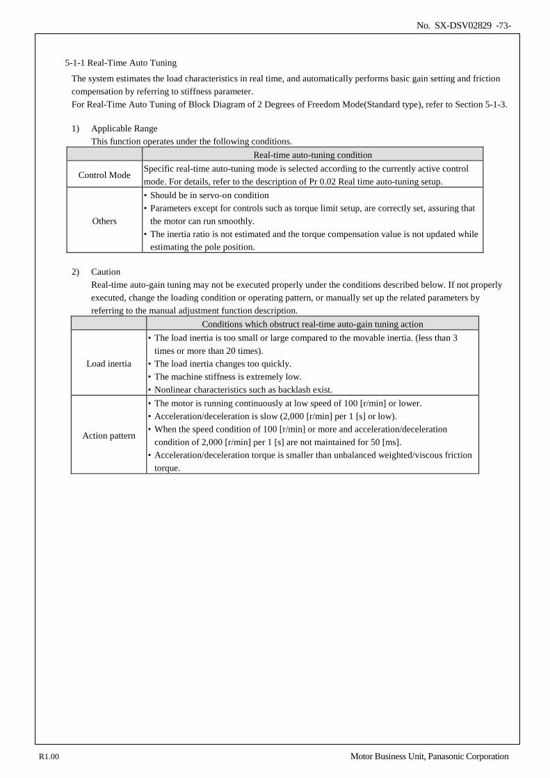
No. SX-DSV02829 -73-
5-1-1 Real-Time Auto Tuning
The system estimates the load characteristics in real time, and automatically performs basic gain setting and friction compensation by referring to stiffness parameter. For Real-Time Auto Tuning of Block Diagram of 2 Degrees of Freedom Mode(Standard type), refer to Section 5-1-3. 1) Applicable Range
This function operates under the following conditions. Real-time auto-tuning condition
Control Mode Specific real-time auto-tuning mode is selected according to the currently active control mode. For details, refer to the description of Pr 0.02 Real time auto-tuning setup.
Others
• Should be in servo-on condition • Parameters except for controls such as torque limit setup, are correctly set, assuring that
the motor can run smoothly. • The inertia ratio is not estimated and the torque compensation value is not updated while
estimating the pole position.
2) Caution Real-time auto-gain tuning may not be executed properly under the conditions described below. If not properly executed, change the loading condition or operating pattern, or manually set up the related parameters by referring to the manual adjustment function description.
Conditions which obstruct real-time auto-gain tuning action
Load inertia
• The load inertia is too small or large compared to the movable inertia. (less than 3 times or more than 20 times).
• The load inertia changes too quickly. • The machine stiffness is extremely low. • Nonlinear characteristics such as backlash exist.
Action pattern
• The motor is running continuously at low speed of 100 [r/min] or lower. • Acceleration/deceleration is slow (2,000 [r/min] per 1 [s] or low). • When the speed condition of 100 [r/min] or more and acceleration/deceleration
condition of 2,000 [r/min] per 1 [s] are not maintained for 50 [ms]. • Acceleration/deceleration torque is smaller than unbalanced weighted/viscous friction
torque.
R1.00 Motor Business Unit, Panasonic Corporation
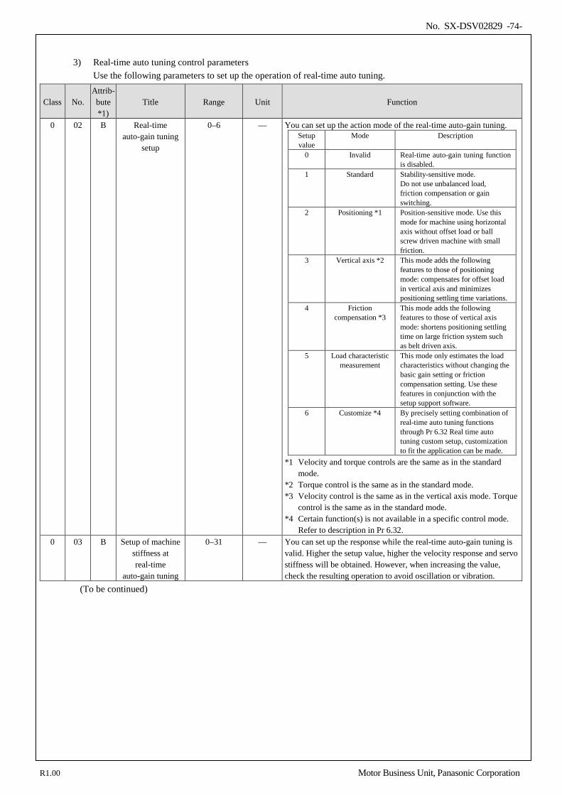
No. SX-DSV02829 -74-
3) Real-time auto tuning control parameters
Use the following parameters to set up the operation of real-time auto tuning.
Class No. Attrib- bute *1)
Title Range Unit Function
0 02 B Real-time auto-gain tuning
setup
0–6 — You can set up the action mode of the real-time auto-gain tuning. Setup value
Mode Description
0 Invalid Real-time auto-gain tuning function is disabled.
1 Standard Stability-sensitive mode. Do not use unbalanced load, friction compensation or gain switching.
2 Positioning *1 Position-sensitive mode. Use this mode for machine using horizontal axis without offset load or ball screw driven machine with small friction.
3 Vertical axis *2 This mode adds the following features to those of positioning mode: compensates for offset load in vertical axis and minimizes positioning settling time variations.
4 Friction compensation *3
This mode adds the following features to those of vertical axis mode: shortens positioning settling time on large friction system such as belt driven axis.
5 Load characteristic measurement
This mode only estimates the load characteristics without changing the basic gain setting or friction compensation setting. Use these features in conjunction with the setup support software.
6 Customize *4 By precisely setting combination of real-time auto tuning functions through Pr 6.32 Real time auto tuning custom setup, customization to fit the application can be made.
*1 Velocity and torque controls are the same as in the standard mode.
*2 Torque control is the same as in the standard mode. *3 Velocity control is the same as in the vertical axis mode. Torque
control is the same as in the standard mode. *4 Certain function(s) is not available in a specific control mode.
Refer to description in Pr 6.32. 0 03 B Setup of machine
stiffness at real-time
auto-gain tuning
0–31 — You can set up the response while the real-time auto-gain tuning is valid. Higher the setup value, higher the velocity response and servo stiffness will be obtained. However, when increasing the value, check the resulting operation to avoid oscillation or vibration.
(To be continued)
R1.00 Motor Business Unit, Panasonic Corporation
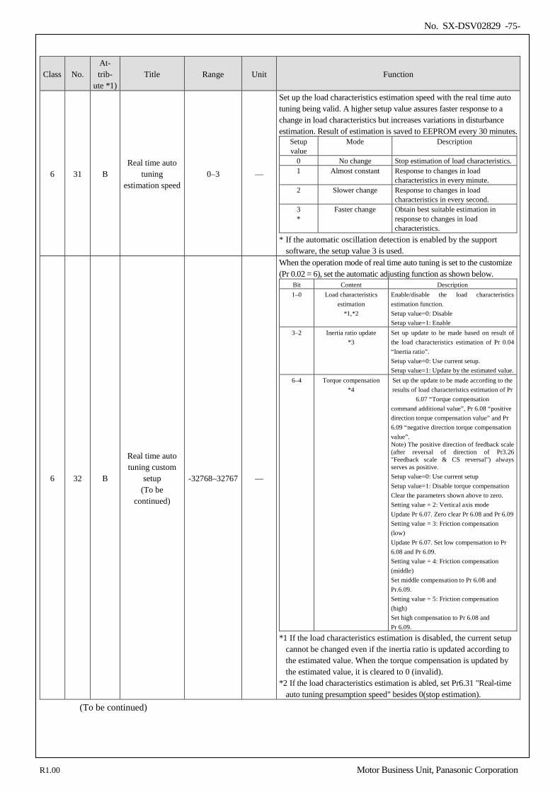
No. SX-DSV02829 -75-
Class No. At- trib-
ute *1) Title Range Unit Function
6 31 B Real time auto
tuning estimation speed
0–3 —
Set up the load characteristics estimation speed with the real time auto tuning being valid. A higher setup value assures faster response to a change in load characteristics but increases variations in disturbance estimation. Result of estimation is saved to EEPROM every 30 minutes.
Setup value
Mode Description
0 No change Stop estimation of load characteristics. 1 Almost constant Response to changes in load
characteristics in every minute. 2 Slower change Response to changes in load
characteristics in every second. 3 *
Faster change Obtain best suitable estimation in response to changes in load characteristics.
* If the automatic oscillation detection is enabled by the support software, the setup value 3 is used.
6 32 B
Real time auto tuning custom
setup (To be
continued)
-32768–32767 —
When the operation mode of real time auto tuning is set to the customize (Pr 0.02 = 6), set the automatic adjusting function as shown below.
Bit Content Description 1–0 Load characteristics
estimation *1,*2
Enable/disable the load characteristics estimation function. Setup value=0: Disable Setup value=1: Enable
3–2 Inertia ratio update *3
Set up update to be made based on result of the load characteristics estimation of Pr 0.04 “Inertia ratio”. Setup value=0: Use current setup. Setup value=1: Update by the estimated value.
6–4 Torque compensation *4
Set up the update to be made according to the results of load characteristics estimation of Pr
6.07 “Torque compensation command additional value”, Pr 6.08 “positive direction torque compensation value” and Pr 6.09 “negative direction torque compensation value”. Note) The positive direction of feedback scale (after reversal of direction of Pr3.26 "Feedback scale & CS reversal") always serves as positive. Setup value=0: Use current setup Setup value=1: Disable torque compensation Clear the parameters shown above to zero. Setting value = 2: Vertical axis mode Update Pr 6.07. Zero clear Pr 6.08 and Pr 6.09 Setting value = 3: Friction compensation (low) Update Pr 6.07. Set low compensation to Pr 6.08 and Pr 6.09. Setting value = 4: Friction compensation (middle) Set middle compensation to Pr 6.08 and Pr.6.09. Setting value = 5: Friction compensation (high) Set high compensation to Pr 6.08 and Pr 6.09.
*1 If the load characteristics estimation is disabled, the current setup cannot be changed even if the inertia ratio is updated according to the estimated value. When the torque compensation is updated by the estimated value, it is cleared to 0 (invalid).
*2 If the load characteristics estimation is abled, set Pr6.31 "Real-time auto tuning presumption speed" besides 0(stop estimation).
(To be continued)
R1.00 Motor Business Unit, Panasonic Corporation
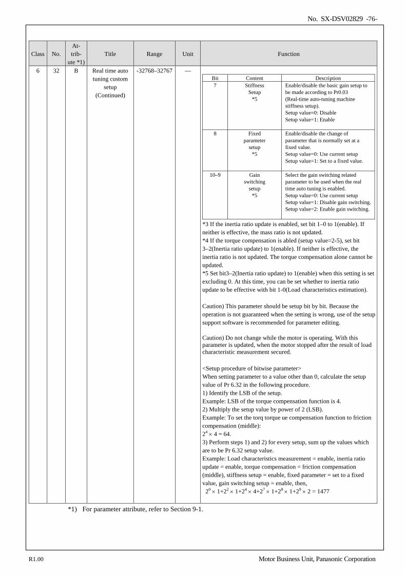
No. SX-DSV02829 -76-
Class No. At- trib-
ute *1) Title Range Unit Function
6 32 B Real time auto tuning custom
setup (Continued)
-32768–32767 — Bit Content Description 7 Stiffness
Setup *5
Enable/disable the basic gain setup to be made according to Pr0.03 (Real-time auto-tuning machine stiffness setup). Setup value=0: Disable Setup value=1: Enable
8 Fixed parameter
setup *5
Enable/disable the change of parameter that is normally set at a fixed value. Setup value=0: Use current setup Setup value=1: Set to a fixed value.
10–9 Gain switching
setup *5
Select the gain switching related parameter to be used when the real time auto tuning is enabled. Setup value=0: Use current setup Setup value=1: Disable gain switching. Setup value=2: Enable gain switching.
*3 If the inertia ratio update is enabled, set bit 1–0 to 1(enable). If neither is effective, the mass ratio is not updated. *4 If the torque compensation is abled (setup value=2-5), set bit 3–2(Inertia ratio update) to 1(enable). If neither is effective, the inertia ratio is not updated. The torque compensation alone cannot be updated. *5 Set bit3–2(Inertia ratio update) to 1(enable) when this setting is set excluding 0. At this time, you can be set whether to inertia ratio update to be effective with bit 1-0(Load characteristics estimation). Caution) This parameter should be setup bit by bit. Because the operation is not guaranteed when the setting is wrong, use of the setup support software is recommended for parameter editing. Caution) Do not change while the motor is operating. With this parameter is updated, when the motor stopped after the result of load characteristic measurement secured. <Setup procedure of bitwise parameter> When setting parameter to a value other than 0, calculate the setup value of Pr 6.32 in the following procedure. 1) Identify the LSB of the setup. Example: LSB of the torque compensation function is 4. 2) Multiply the setup value by power of 2 (LSB). Example: To set the torq torque ue compensation function to friction compensation (middle): 24 × 4 = 64. 3) Perform steps 1) and 2) for every setup, sum up the values which are to be Pr 6.32 setup value. Example: Load characteristics measurement = enable, inertia ratio update = enable, torque compensation = friction compensation (middle), stiffness setup = enable, fixed parameter = set to a fixed value, gain switching setup = enable, then, 20 × 1+22 × 1+24 × 4+27 × 1+28 × 1+29 × 2 = 1477
*1) For parameter attribute, refer to Section 9-1.
R1.00 Motor Business Unit, Panasonic Corporation
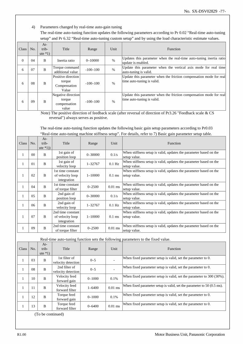
No. SX-DSV02829 -77-
4) Parameters changed by real-time auto-gain tuning
The real-time auto-tuning function updates the following parameters according to Pr 0.02 “Real-time auto-tuning setup” and Pr 6.32 “Real-time auto-tuning custom setup” and by using the load characteristic estimate values.
Class No. At- trib-
ute *1) Title Range Unit Function
0 04 B Inertia ratio 0–10000 % Updates this parameter when the real-time auto-tuning inertia ratio update is enabled.
6 07 B Torque command additional value -100–100 % Update this parameter when the vertical axis mode for real time
auto-tuning is valid.
6 08 B
Positive direction torque
Compensation Value
-100–100 %
Update this parameter when the friction compensation mode for real time auto-tuning is valid.
6 09 B
Negative direction torque
compensation value
-100–100 %
Update this parameter when the friction compensation mode for real time auto-tuning is valid.
Note) The positive direction of feedback scale (after reversal of direction of Pr3.26 "Feedback scale & CS reversal") always serves as positive.
The real-time auto-tuning function updates the following basic gain setup parameters according to Pr0.03 “Real-time auto-tuning machine stiffness setup”. For details, refer to 7) Basic gain parameter setup table.
Class No. At- trib-
ute *1)) Title Range Unit Function
1 00 B 1st gain of position loop 0–30000 0.1/s When stiffness setup is valid, updates the parameter based on the
setup value.
1 01 B 1st gain of velocity loop 1–32767 0.1 Hz When stiffness setup is valid, updates the parameter based on the
setup value.
1 02 B 1st time constant of velocity loop
integration 1–10000 0.1 ms
When stiffness setup is valid, updates the parameter based on the setup value.
1 04 B 1st time constant of torque filter 0–2500 0.01 ms When stiffness setup is valid, updates the parameter based on the
setup value.
1 05 B 2nd gain of position loop 0–30000 0.1/s When stiffness setup is valid, updates the parameter based on the
setup value.
1 06 B 2nd gain of velocity loop 1–32767 0.1 Hz When stiffness setup is valid, updates the parameter based on the
setup value.
1 07 B 2nd time constant of velocity loop
integration 1–10000 0.1 ms
When stiffness setup is valid, updates the parameter based on the setup value.
1 09 B 2nd time constant of torque filter 0–2500 0.01 ms When stiffness setup is valid, updates the parameter based on the
setup value.
Real-time auto-tuning function sets the following parameters to the fixed value.
Class No. At- trib-
ute *1) Title Range Unit Function
1 03 B 1st filter of velocity detection 0–5 - When fixed parameter setup is valid, set the parameter to 0.
1 08 B 2nd filter of velocity detection 0–5 - When fixed parameter setup is valid, set the parameter to 0.
1 10 B Velocity feed forward gain 0–1000 0.1% When fixed parameter setup is valid, set the parameter to 300 (30%).
1 11 B Velocity feed forward filter 1–6400 0.01 ms When fixed parameter setup is valid, set the parameter to 50 (0.5 ms).
1 12 B Torque feed forward gain 0–1000 0.1% When fixed parameter setup is valid, set the parameter to 0.
1 13 B Torque feed forward filter 0–6400 0.01 ms When fixed parameter setup is valid, set the parameter to 0.
(To be continued)
R1.00 Motor Business Unit, Panasonic Corporation
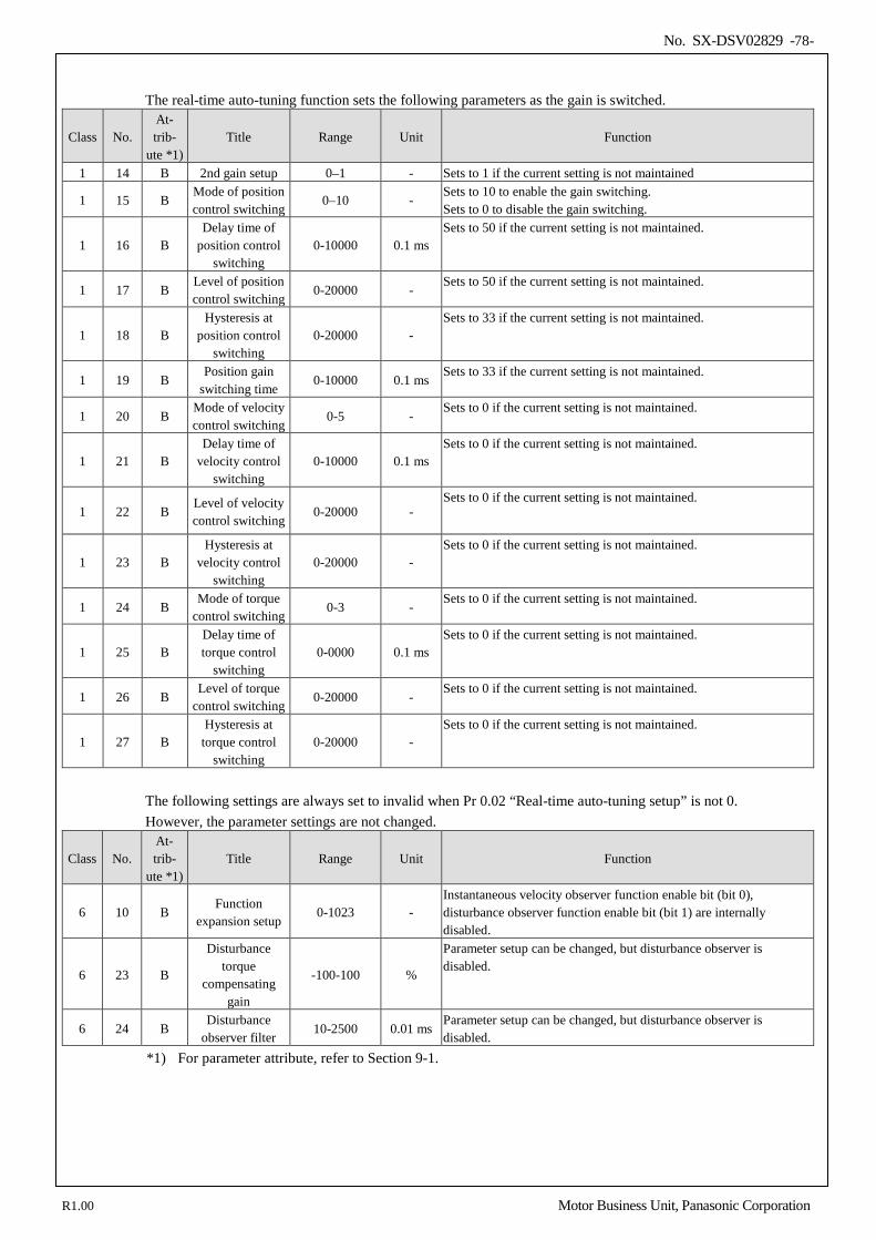
No. SX-DSV02829 -78-
The real-time auto-tuning function sets the following parameters as the gain is switched.
Class No. At- trib-
ute *1) Title Range Unit Function
1 14 B 2nd gain setup 0–1 - Sets to 1 if the current setting is not maintained
1 15 B Mode of position control switching
0–10 - Sets to 10 to enable the gain switching. Sets to 0 to disable the gain switching.
1 16 B Delay time of
position control switching
0-10000 0.1 ms Sets to 50 if the current setting is not maintained.
1 17 B Level of position control switching
0-20000 - Sets to 50 if the current setting is not maintained.
1 18 B Hysteresis at
position control switching
0-20000 - Sets to 33 if the current setting is not maintained.
1 19 B Position gain
switching time 0-10000 0.1 ms
Sets to 33 if the current setting is not maintained.
1 20 B Mode of velocity control switching
0-5 - Sets to 0 if the current setting is not maintained.
1 21 B Delay time of
velocity control switching
0-10000 0.1 ms Sets to 0 if the current setting is not maintained.
1 22 B Level of velocity control switching
0-20000 - Sets to 0 if the current setting is not maintained.
1 23 B Hysteresis at
velocity control switching
0-20000 - Sets to 0 if the current setting is not maintained.
1 24 B Mode of torque
control switching 0-3 -
Sets to 0 if the current setting is not maintained.
1 25 B Delay time of torque control
switching 0-0000 0.1 ms
Sets to 0 if the current setting is not maintained.
1 26 B Level of torque
control switching 0-20000 -
Sets to 0 if the current setting is not maintained.
1 27 B Hysteresis at
torque control switching
0-20000 - Sets to 0 if the current setting is not maintained.
The following settings are always set to invalid when Pr 0.02 “Real-time auto-tuning setup” is not 0. However, the parameter settings are not changed.
Class No. At- trib-
ute *1) Title Range Unit Function
6 10 B Function
expansion setup 0-1023 -
Instantaneous velocity observer function enable bit (bit 0), disturbance observer function enable bit (bit 1) are internally disabled.
6 23 B
Disturbance torque
compensating gain
-100-100 %
Parameter setup can be changed, but disturbance observer is disabled.
6 24 B Disturbance
observer filter 10-2500 0.01 ms
Parameter setup can be changed, but disturbance observer is disabled.
*1) For parameter attribute, refer to Section 9-1.
R1.00 Motor Business Unit, Panasonic Corporation
No. SX-DSV02829 -79-
5) How to Operate
When Pr 0.02 (Setup of real-time auto-gain tuning mode) is set to a value other than 0, control parameter is automatically set according to Pr0.03 “Real-time auto-tuning machine stiffness setup”. When the servo is ON, enter operation command after about 100ms. When the load characteristic is correctly estimated, Pr 0.04 Inertia ratio is updated. With certain mode settings, Pr 6.07 Torque command addition value, Pr 6.08 Positive direction torque compensation value and Pr 6.09 Negative direction torque compensation value will be changed. When value of Pr0.03 “Real-time auto-tuning machine stiffness setup” is increased, the motor responsiveness will be improved. Determine the most appropriate stiffness in relation to the positioning setup time and vibration condition. Note) The positive direction of feedback scale (after reversal of direction of Pr3.26 "Feedback scale &
CS reversal") always serves as positive.
6) Other cautions [1] Immediately after the first servo-on upon start up; or after increasing Pr0.03 “Real-time auto-tuning machine
stiffness setup”, abnormal sound or oscillation may be generated until the load characteristics is stabilized. If such abnormality lasts or repeats for 3 or more reciprocating operations, take the following countermeasures. 1) Lower the setting value of Pr0.03 “Real-time auto-tuning machine stiffness setup”. 2) Set Pr 0.02 Real-time auto-tuning setup to 0 to disable the real-time auto-tuning. 3) Set Pr 0.04 Inertia ratio to the calculational value of the equipment and set Pr 6.07 Torque command
addition value, Pr 6.08 Positive direction torque compensation value and Pr 6.09 Negative direction torque compensation value to 0.
[2] When abnormal noise and oscillation occur, Pr 0.04 (Inertia ratio) or Pr 6.07 (Torque command additional value), Pr 6.08 (Positive direction torque compensation value), Pr 6.09 (Negative direction torque compensation value) might have changed to extreme values. Take the same measures as described in the setp 3) above in these cases.
[3] Among the results of real-time auto-gain tuning, Pr 0.04 (Inertia ratio) and Pr 6.07 (Torque command additional value), Pr 6.08 (Positive direction torque compensation value), Pr 6.09 (Negative direction torque compensation value) will be written to EEPROM every 30 minutes. When you turn on the power again, the auto-gain tuning will be executed using the latest data as initial values. If power is turned off within 30 minutes after the end of tuning process, the result of the real-time auto-tuning is not saved. If the result is not saved, manually write parameters to EEPROM and then turn off power.
[4] The control gain is updated when the motor is stopped. Therefore, if motor is not stopped because gain is excessively low or commands are given continually in one direction, the change in Pr0.03 “Real-time auto-tuning machine stiffness setup” may not be reflected. In this case, abnormal sound or oscillation may be generated depending on the stiffness setting that is reflected after the motor stops. After the stiffness setting is changed, be sure to stop the motor and check that the stiffness setting is reflected before performing next operation.
Note) The positive direction of feedback scale (after reversal of direction of Pr3.26 "Feedback scale &
CS reversal") always serves as positive
R1.00 Motor Business Unit, Panasonic Corporation
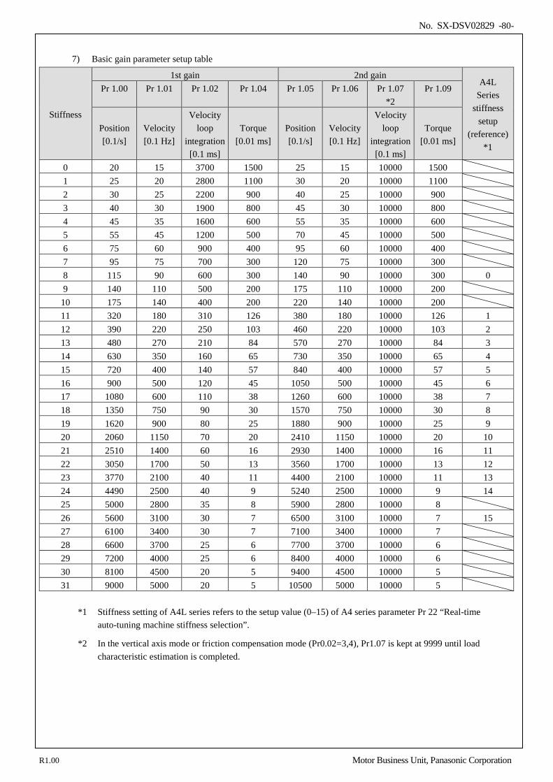
No. SX-DSV02829 -80-
7) Basic gain parameter setup table
Stiffness
1st gain 2nd gain A4L
Series stiffness
setup (reference)
*1
Pr 1.00 Pr 1.01 Pr 1.02 Pr 1.04 Pr 1.05 Pr 1.06 Pr 1.07 *2
Pr 1.09
Position [0.1/s]
Velocity [0.1 Hz]
Velocity loop
integration [0.1 ms]
Torque [0.01 ms]
Position [0.1/s]
Velocity [0.1 Hz]
Velocity loop
integration [0.1 ms]
Torque [0.01 ms]
0 20 15 3700 1500 25 15 10000 1500 1 25 20 2800 1100 30 20 10000 1100 2 30 25 2200 900 40 25 10000 900 3 40 30 1900 800 45 30 10000 800 4 45 35 1600 600 55 35 10000 600 5 55 45 1200 500 70 45 10000 500 6 75 60 900 400 95 60 10000 400 7 95 75 700 300 120 75 10000 300 8 115 90 600 300 140 90 10000 300 0 9 140 110 500 200 175 110 10000 200
10 175 140 400 200 220 140 10000 200 11 320 180 310 126 380 180 10000 126 1 12 390 220 250 103 460 220 10000 103 2 13 480 270 210 84 570 270 10000 84 3 14 630 350 160 65 730 350 10000 65 4 15 720 400 140 57 840 400 10000 57 5 16 900 500 120 45 1050 500 10000 45 6 17 1080 600 110 38 1260 600 10000 38 7 18 1350 750 90 30 1570 750 10000 30 8 19 1620 900 80 25 1880 900 10000 25 9 20 2060 1150 70 20 2410 1150 10000 20 10 21 2510 1400 60 16 2930 1400 10000 16 11 22 3050 1700 50 13 3560 1700 10000 13 12 23 3770 2100 40 11 4400 2100 10000 11 13 24 4490 2500 40 9 5240 2500 10000 9 14 25 5000 2800 35 8 5900 2800 10000 8 26 5600 3100 30 7 6500 3100 10000 7 15 27 6100 3400 30 7 7100 3400 10000 7 28 6600 3700 25 6 7700 3700 10000 6 29 7200 4000 25 6 8400 4000 10000 6 30 8100 4500 20 5 9400 4500 10000 5 31 9000 5000 20 5 10500 5000 10000 5
*1 Stiffness setting of A4L series refers to the setup value (0–15) of A4 series parameter Pr 22 “Real-time
auto-tuning machine stiffness selection”.
*2 In the vertical axis mode or friction compensation mode (Pr0.02=3,4), Pr1.07 is kept at 9999 until load characteristic estimation is completed.
R1.00 Motor Business Unit, Panasonic Corporation
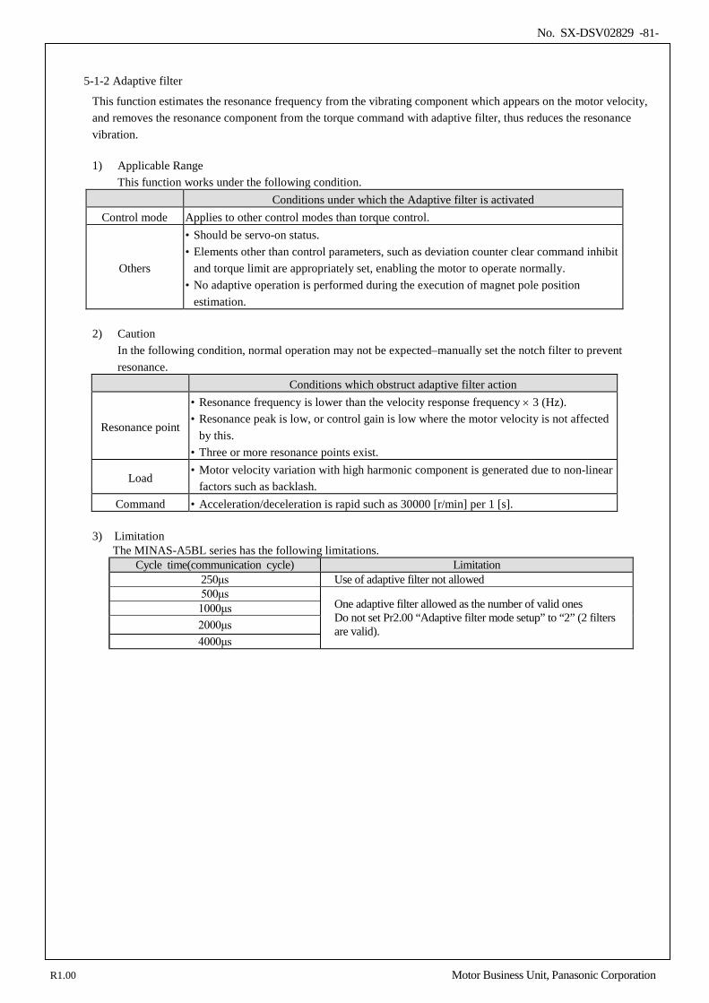
No. SX-DSV02829 -81-
5-1-2 Adaptive filter
This function estimates the resonance frequency from the vibrating component which appears on the motor velocity, and removes the resonance component from the torque command with adaptive filter, thus reduces the resonance vibration. 1) Applicable Range
This function works under the following condition. Conditions under which the Adaptive filter is activated
Control mode Applies to other control modes than torque control.
Others
• Should be servo-on status. • Elements other than control parameters, such as deviation counter clear command inhibit
and torque limit are appropriately set, enabling the motor to operate normally. • No adaptive operation is performed during the execution of magnet pole position
estimation.
2) Caution In the following condition, normal operation may not be expected–manually set the notch filter to prevent resonance.
Conditions which obstruct adaptive filter action
Resonance point
• Resonance frequency is lower than the velocity response frequency × 3 (Hz). • Resonance peak is low, or control gain is low where the motor velocity is not affected
by this. • Three or more resonance points exist.
Load • Motor velocity variation with high harmonic component is generated due to non-linear
factors such as backlash. Command • Acceleration/deceleration is rapid such as 30000 [r/min] per 1 [s].
3) Limitation
The MINAS-A5BL series has the following limitations. Cycle time(communication cycle) Limitation
250μs Use of adaptive filter not allowed 500μs
One adaptive filter allowed as the number of valid ones Do not set Pr2.00 “Adaptive filter mode setup” to “2” (2 filters are valid).
1000μs 2000μs 4000μs
R1.00 Motor Business Unit, Panasonic Corporation
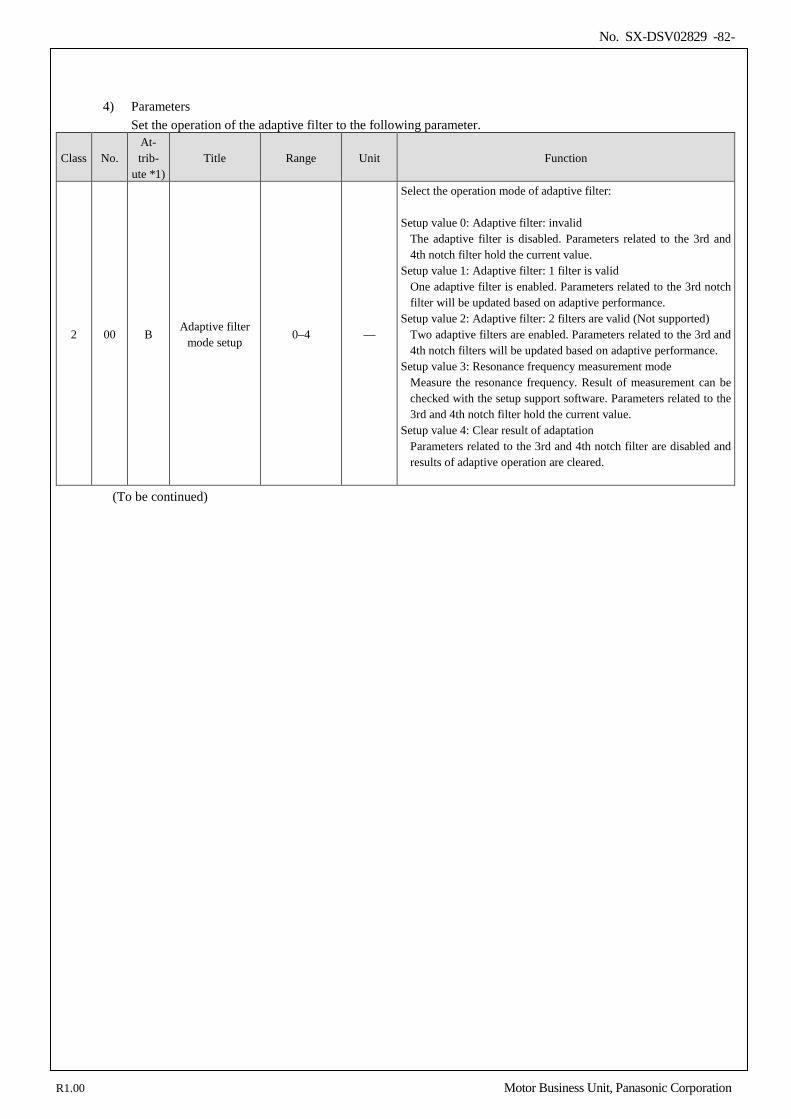
No. SX-DSV02829 -82-
4) Parameters Set the operation of the adaptive filter to the following parameter.
Class No. At- trib-
ute *1) Title Range Unit Function
2 00 B Adaptive filter
mode setup 0–4 —
Select the operation mode of adaptive filter: Setup value 0: Adaptive filter: invalid
The adaptive filter is disabled. Parameters related to the 3rd and 4th notch filter hold the current value.
Setup value 1: Adaptive filter: 1 filter is valid One adaptive filter is enabled. Parameters related to the 3rd notch filter will be updated based on adaptive performance.
Setup value 2: Adaptive filter: 2 filters are valid (Not supported) Two adaptive filters are enabled. Parameters related to the 3rd and 4th notch filters will be updated based on adaptive performance.
Setup value 3: Resonance frequency measurement mode Measure the resonance frequency. Result of measurement can be checked with the setup support software. Parameters related to the 3rd and 4th notch filter hold the current value.
Setup value 4: Clear result of adaptation Parameters related to the 3rd and 4th notch filter are disabled and results of adaptive operation are cleared.
(To be continued)
R1.00 Motor Business Unit, Panasonic Corporation
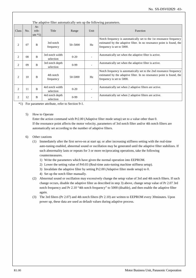
No. SX-DSV02829 -83-
The adaptive filter automatically sets up the following parameters.
Class No. At- trib-
ute *1) Title Range Unit Function
2 07 B 3rd notch frequency
50–5000 Hz
Notch frequency is automatically set to the 1st resonance frequency estimated by the adaptive filter. In no resonance point is found, the frequency is set to 5000.
2 08 B 3rd notch width
selection 0-20 -
Automatically set when the adaptive filter is active.
2 09 B 3rd notch depth
selection 0-99 -
Automatically set when the adaptive filter is active.
2 10 B 4th notch frequency
50-5000 Hz
Notch frequency is automatically set to the 2nd resonance frequency estimated by the adaptive filter. In no resonance point is found, the frequency is set to 5000.
2 11 B 4rd notch width
selection 0-20 -
Automatically set when 2 adaptive filters are active.
2 12 B 4rd notch depth
selection 0-99 -
Automatically set when 2 adaptive filters are active.
*1) For parameter attribute, refer to Section 9-1.
5) How to Operate
Enter the action command with Pr2.00 (Adaptive filter mode setup) set to a value other than 0. If the resonance point affects the motor velocity, parameters of 3rd notch filter and/or 4th notch filters are automatically set according to the number of adaptive filters.
6) Other cautions (1) Immediately after the first servo-on at start up; or after increasing stiffness setting with the real-time
auto-tuning enabled, abnormal sound or oscillation may be generated until the adaptive filter stabilizes. If such abnormality lasts or repeats for 3 or more reciprocating operations, take the following countermeasures. 1) Write the parameters which have given the normal operation into EEPROM. 2) Lower the setting value of Pr0.03 (Real-time auto-tuning machine stiffness setup). 3) Invalidate the adaptive filter by setting Pr2.00 (Adaptive filter mode setup) to 0. 4) Set up the notch filter manually.
(2) Abnormal sound or oscillation may excessively change the setup value of 3rd and 4th notch filters. If such change occurs, disable the adaptive filter as described in step 3) above, change setup value of Pr 2.07 3rd notch frequency and Pr 2.10 “4th notch frequency” to 5000 (disable), and then enable the adaptive filter again.
(3) The 3rd filters (Pr 2.07) and 4th notch filters (Pr 2.10) are written to EEPROM every 30minutes. Upon power up, these data are used as default values during adaptive process.
R1.00 Motor Business Unit, Panasonic Corporation
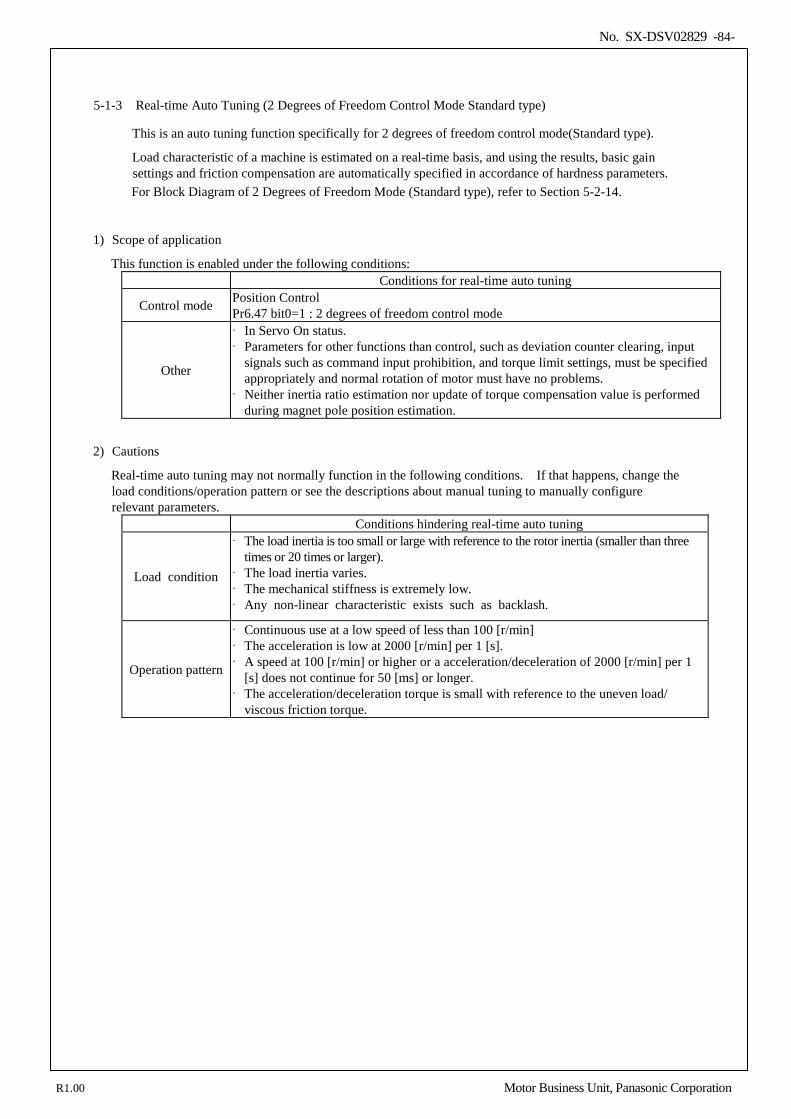
No. SX-DSV02829 -84-
5-1-3 Real-time Auto Tuning (2 Degrees of Freedom Control Mode Standard type)
This is an auto tuning function specifically for 2 degrees of freedom control mode(Standard type).
Load characteristic of a machine is estimated on a real-time basis, and using the results, basic gain settings and friction compensation are automatically specified in accordance of hardness parameters.
For Block Diagram of 2 Degrees of Freedom Mode (Standard type), refer to Section 5-2-14. 1) Scope of application
This function is enabled under the following conditions: Conditions for real-time auto tuning
Control mode Position Control Pr6.47 bit0=1 : 2 degrees of freedom control mode
Other
In Servo On status. Parameters for other functions than control, such as deviation counter clearing, input
signals such as command input prohibition, and torque limit settings, must be specified appropriately and normal rotation of motor must have no problems.
Neither inertia ratio estimation nor update of torque compensation value is performed during magnet pole position estimation.
2) Cautions
Real-time auto tuning may not normally function in the following conditions. If that happens, change the load conditions/operation pattern or see the descriptions about manual tuning to manually configure relevant parameters.
Conditions hindering real-time auto tuning
Load condition
The load inertia is too small or large with reference to the rotor inertia (smaller than three times or 20 times or larger).
The load inertia varies. The mechanical stiffness is extremely low. Any non-linear characteristic exists such as backlash.
Operation pattern
Continuous use at a low speed of less than 100 [r/min] The acceleration is low at 2000 [r/min] per 1 [s]. A speed at 100 [r/min] or higher or a acceleration/deceleration of 2000 [r/min] per 1
[s] does not continue for 50 [ms] or longer. The acceleration/deceleration torque is small with reference to the uneven load/
viscous friction torque.
R1.00 Motor Business Unit, Panasonic Corporation
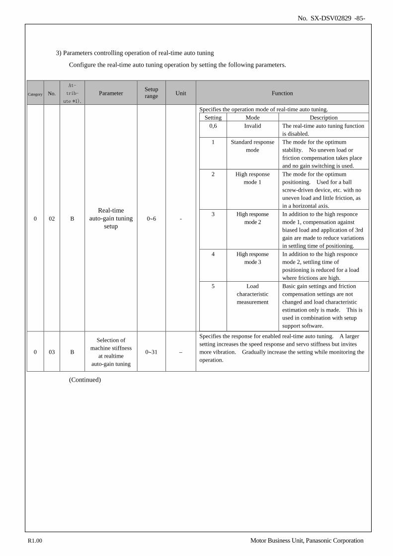
No. SX-DSV02829 -85-
3) Parameters controlling operation of real-time auto tuning
Configure the real-time auto tuning operation by setting the following parameters.
Category No. At-
trib-
ute *1). Parameter
Setup range Unit Function
0 02 B Real-time
auto-gain tuning setup
0∼6 -
Specifies the operation mode of real-time auto tuning. Setting Mode Description
0,6 Invalid The real-time auto tuning function is disabled.
1 Standard response mode
The mode for the optimum stability. No uneven load or friction compensation takes place and no gain switching is used.
2 High response mode 1
The mode for the optimum positioning. Used for a ball screw-driven device, etc. with no uneven load and little friction, as in a horizontal axis.
3 High response mode 2
In addition to the high responce mode 1, compensation against biased load and application of 3rd gain are made to reduce variations in settling time of positioning.
4 High response mode 3
In addition to the high responce mode 2, settling time of positioning is reduced for a load where frictions are high.
5 Load characteristic measurement
Basic gain settings and friction compensation settings are not changed and load characteristic estimation only is made. This is used in combination with setup support software.
0 03 B
Selection of machine stiffness
at realtime auto-gain tuning
0∼31 −
Specifies the response for enabled real-time auto tuning. A larger setting increases the speed response and servo stiffness but invites more vibration. Gradually increase the setting while monitoring the operation.
(Continued)
R1.00 Motor Business Unit, Panasonic Corporation
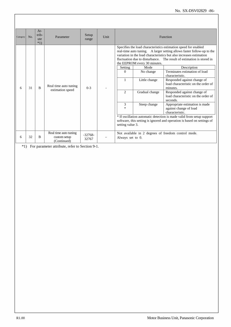
No. SX-DSV02829 -86-
Category No.
At- trib- ute *1)
Parameter Setup range Unit Function
6 31 B Real time auto tuning estimation speed 0-3 -
Specifies the load characteristics estimation speed for enabled real-time auto tuning. A larger setting allows faster follow-up to the variation in the load characteristics but also increases estimation fluctuation due to disturbance. The result of estimation is stored in the EEPROM every 30 minutes.
Setting Mode Description 0 No change Terminates estimation of load
characteristic. 1 Little change Responded against change of
load characteristic on the order of minutes.
2 Gradual change Responded against change of load characteristic on the order of seconds.
3 *
Steep change Appropriate estimation is made against change of load characteristic.
* If oscillation automatic detection is made valid from setup support software, this setting is ignored and operation is based on settings of setting value 3.
6 32 B Real time auto tuning
custom setup (Continued)
-32768-32767 −
Not available in 2 degrees of freedom control mode. Always set to 0.
*1) For parameter attribute, refer to Section 9-1.
R1.00 Motor Business Unit, Panasonic Corporation
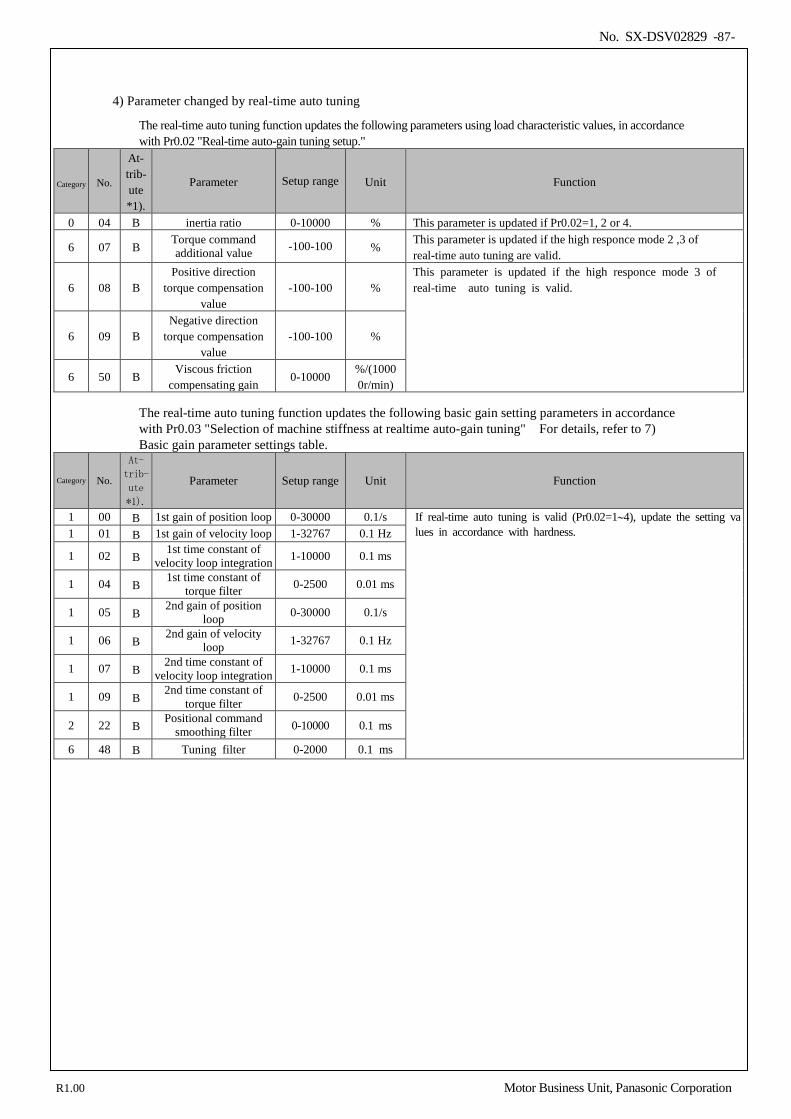
No. SX-DSV02829 -87-
4) Parameter changed by real-time auto tuning
The real-time auto tuning function updates the following parameters using load characteristic values, in accordance with Pr0.02 "Real-time auto-gain tuning setup."
Category No.
At- trib- ute *1).
Parameter Setup range Unit Function
0 04 B inertia ratio 0-10000 % This parameter is updated if Pr0.02=1, 2 or 4.
6 07 B Torque command additional value -100-100 %
This parameter is updated if the high responce mode 2 ,3 of real-time auto tuning are valid.
6 08 B Positive direction
torque compensation value
-100-100 % This parameter is updated if the high responce mode 3 of real-time auto tuning is valid.
6 09 B Negative direction
torque compensation value
-100-100 %
6 50 B Viscous friction
compensating gain 0-10000
%/(10000r/min)
The real-time auto tuning function updates the following basic gain setting parameters in accordance with Pr0.03 "Selection of machine stiffness at realtime auto-gain tuning" For details, refer to 7) Basic gain parameter settings table.
Category No.
At-
trib-
ute
*1).
Parameter Setup range Unit Function
1 00 B 1st gain of position loop 0-30000 0.1/s If real-time auto tuning is valid (Pr0.02=1∼4), update the setting values in accordance with hardness. 1 01 B 1st gain of velocity loop 1-32767 0.1 Hz
1 02 B 1st time constant of
velocity loop integration 1-10000 0.1 ms
1 04 B 1st time constant of
torque filter 0-2500 0.01 ms
1 05 B 2nd gain of position
loop 0-30000 0.1/s
1 06 B 2nd gain of velocity
loop 1-32767 0.1 Hz
1 07 B 2nd time constant of
velocity loop integration 1-10000 0.1 ms
1 09 B 2nd time constant of
torque filter 0-2500 0.01 ms
2 22 B Positional command
smoothing filter 0-10000 0.1 ms
6 48 B Tuning filter 0-2000 0.1 ms
R1.00 Motor Business Unit, Panasonic Corporation
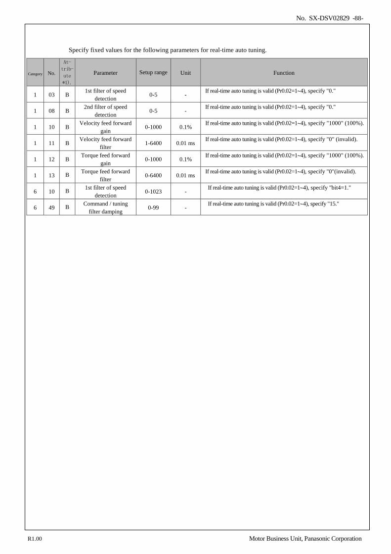
No. SX-DSV02829 -88-
Specify fixed values for the following parameters for real-time auto tuning.
Category No.
At-
trib-
ute
*1).
Parameter Setup range Unit Function
1 03 B 1st filter of speed
detection 0-5 -
If real-time auto tuning is valid (Pr0.02=1∼4), specify "0."
1 08 B 2nd filter of speed
detection 0-5 -
If real-time auto tuning is valid (Pr0.02=1∼4), specify "0."
1 10 B Velocity feed forward
gain 0-1000 0.1%
If real-time auto tuning is valid (Pr0.02=1∼4), specify "1000" (100%).
1 11 B Velocity feed forward
filter 1-6400 0.01 ms
If real-time auto tuning is valid (Pr0.02=1∼4), specify "0" (invalid).
1 12 B Torque feed forward
gain 0-1000 0.1%
If real-time auto tuning is valid (Pr0.02=1∼4), specify "1000" (100%).
1 13 B Torque feed forward filter
0-6400 0.01 ms If real-time auto tuning is valid (Pr0.02=1∼4), specify "0"(invalid).
6 10 B 1st filter of speed detection
0-1023 - If real-time auto tuning is valid (Pr0.02=1∼4), specify "bit4=1."
6 49 B Command / tuning filter damping
0-99 - If real-time auto tuning is valid (Pr0.02=1∼4), specify "15."
R1.00 Motor Business Unit, Panasonic Corporation
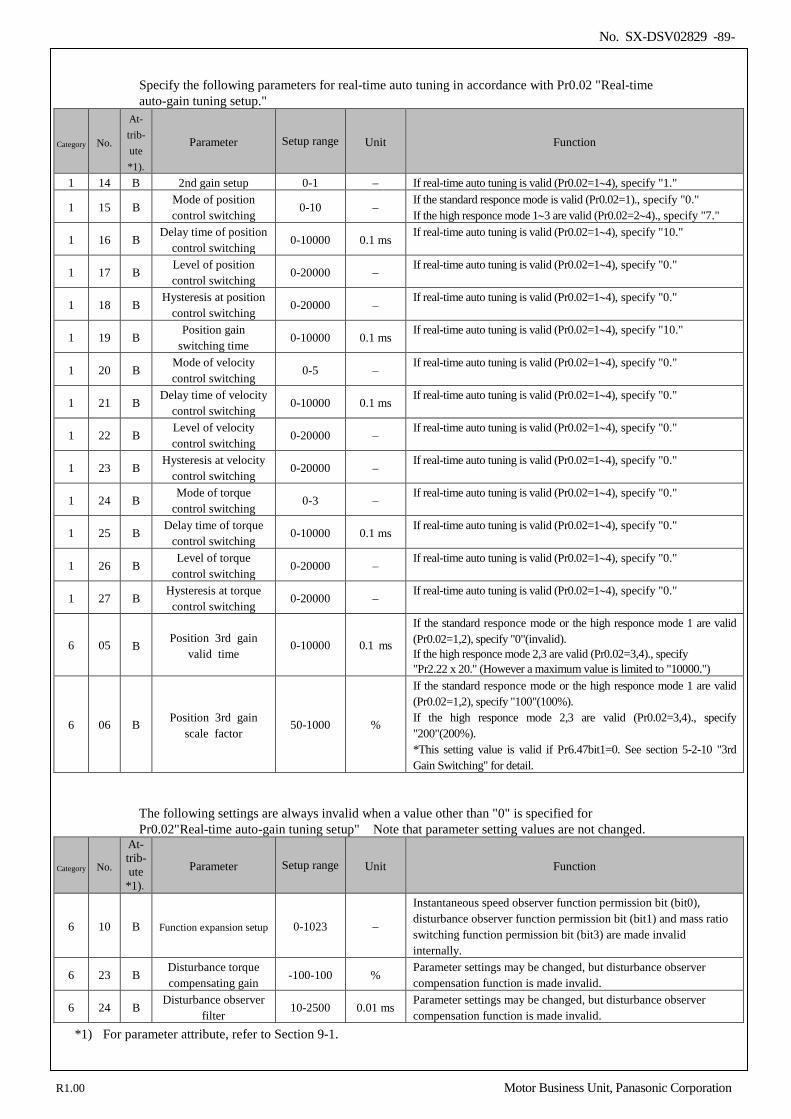
No. SX-DSV02829 -89-
Specify the following parameters for real-time auto tuning in accordance with Pr0.02 "Real-time auto-gain tuning setup."
Category No.
At- trib- ute *1).
Parameter Setup range Unit Function
1 14 B 2nd gain setup 0-1 − If real-time auto tuning is valid (Pr0.02=1∼4), specify "1."
1 15 B Mode of position control switching
0-10 − If the standard responce mode is valid (Pr0.02=1)., specify "0." If the high responce mode 1∼3 are valid (Pr0.02=2∼4)., specify "7."
1 16 B Delay time of position
control switching 0-10000 0.1 ms
If real-time auto tuning is valid (Pr0.02=1∼4), specify "10."
1 17 B Level of position control switching
0-20000 − If real-time auto tuning is valid (Pr0.02=1∼4), specify "0."
1 18 B Hysteresis at position
control switching 0-20000 −
If real-time auto tuning is valid (Pr0.02=1∼4), specify "0."
1 19 B Position gain
switching time 0-10000 0.1 ms
If real-time auto tuning is valid (Pr0.02=1∼4), specify "10."
1 20 B Mode of velocity control switching
0-5 − If real-time auto tuning is valid (Pr0.02=1∼4), specify "0."
1 21 B Delay time of velocity
control switching 0-10000 0.1 ms
If real-time auto tuning is valid (Pr0.02=1∼4), specify "0."
1 22 B Level of velocity control switching
0-20000 − If real-time auto tuning is valid (Pr0.02=1∼4), specify "0."
1 23 B Hysteresis at velocity
control switching 0-20000 −
If real-time auto tuning is valid (Pr0.02=1∼4), specify "0."
1 24 B Mode of torque
control switching 0-3 −
If real-time auto tuning is valid (Pr0.02=1∼4), specify "0."
1 25 B Delay time of torque
control switching 0-10000 0.1 ms
If real-time auto tuning is valid (Pr0.02=1∼4), specify "0."
1 26 B Level of torque
control switching 0-20000 −
If real-time auto tuning is valid (Pr0.02=1∼4), specify "0."
1 27 B Hysteresis at torque control switching
0-20000 − If real-time auto tuning is valid (Pr0.02=1∼4), specify "0."
6 05 B Position 3rd gain
valid time 0-10000 0.1 ms
If the standard responce mode or the high responce mode 1 are valid (Pr0.02=1,2), specify "0"(invalid). If the high responce mode 2,3 are valid (Pr0.02=3,4)., specify "Pr2.22 x 20." (However a maximum value is limited to "10000.")
6 06 B Position 3rd gain scale factor
50-1000 %
If the standard responce mode or the high responce mode 1 are valid (Pr0.02=1,2), specify "100"(100%). If the high responce mode 2,3 are valid (Pr0.02=3,4)., specify "200"(200%). *This setting value is valid if Pr6.47bit1=0. See section 5-2-10 "3rd Gain Switching" for detail.
The following settings are always invalid when a value other than "0" is specified for Pr0.02"Real-time auto-gain tuning setup" Note that parameter setting values are not changed.
Category No.
At- trib- ute
*1).
Parameter Setup range Unit Function
6 10 B Function expansion setup 0-1023 −
Instantaneous speed observer function permission bit (bit0), disturbance observer function permission bit (bit1) and mass ratio switching function permission bit (bit3) are made invalid internally.
6 23 B Disturbance torque compensating gain
-100-100 % Parameter settings may be changed, but disturbance observer compensation function is made invalid.
6 24 B Disturbance observer
filter 10-2500 0.01 ms
Parameter settings may be changed, but disturbance observer compensation function is made invalid.
*1) For parameter attribute, refer to Section 9-1.
R1.00 Motor Business Unit, Panasonic Corporation
No. SX-DSV02829 -90-
5) Usage
Control parameters are specified automatically if a value other than "0" is specified for Pr0.02 "Real-time auto-gain tuning setup" in accordance with Pr0.03 "Selection of machine stiffness at realtime auto-gain tuning"
Input an operation command after the drive has been enabled by Servo On. If estimation load characteristic is successful, Pr0.04 "Inertia ratio" is updated. In addition, some mode setting may cause changes of Pr6.07 "Torque command additional value", Pr6.08 "Positive direction torque compensation value", Pr6.09 "Negative direction torque compensation value", and Pr6.50 "Viscous friction compensating gain."
Specifying higher settings for Pr0.03 "Selection of machine stiffness at realtime auto-gain tuning" can increase response of motor. Adjust to the optimum value while monitoring the positioning stabilization time and vibration conditions.
6) Other cautions
1) Strange noises or vibrations may occur on the first action of turning on the servo immediately after startup or setting higher value of Pr0.03 "Selection of machine stiffness at realtime auto-gain tuning" until estimation of load characteristic becomes stable. This is not a fault if the function becomes stable soon. If oscillation or continued generation of abnormal noise through three or more reciprocating movements often occurs, take the following steps. 1) Specify lower value for Pr0.03 "Selection of machine stiffness at realtime auto-gain tuning" 2) Specify "0" for Pr0.02 "Real-time auto-gain tuning setup" and make real-time auto tuning invalid. 3) Specify a theoretical value of device for Pr0.04 "Inertia ratio" and specify "0" for Pr6.07 " Torque
command additional value", Pr6.08 "Positive direction torque compensation value", Pr6.09 "Negative direction torque compensation value" and Pr6.50 "Viscous friction compensating gain."
2) After occurrence of strange noises or vibrations, values of Pr0.04 "Inertia ratio," Pr6.07 " Torque command additional value", Pr6.08 "Positive direction torque compensation value", Pr6.09 "Negative direction torque compensation value", or Pr6.50 "Viscous friction compensating gain" may have been changed into extreme values. If this is the case, take Step 3) above.
3) The results of real-time automatic gain tuning, such as Pr0.04 "Inertia ratio," Pr6.07 " Torque command additional value", Pr6.08 "Positive direction torque compensation value", Pr6.09 "Negative direction torque compensation value", and Pr6.50 "Viscous friction compensating gain" are written in EEPROM in every 30 minutes. Upon restarting of power, auto tuning is performed using the data for initial values. The results of real-time auto gain tuning are not stored if the power is turned off before 30 minutes have elapsed. In this case, manually write the parameters to the EEPROM before turning off the power.
4) The control gain is updated when the motor is stopped. Therefore, if motor is not stopped because gain is excessively low or commands are given continually in one direction, the change in Pr0.03 “Real-time auto-tuning machine stiffness setup” may not be reflected. In this case, abnormal sound or oscillation may be generated depending on the stiffness setting that is reflected after the motor stops.
After the stiffness setting is changed, be sure to stop the motor and check that the stiffness setting is reflected before performing next operation.
R1.00 Motor Business Unit, Panasonic Corporation
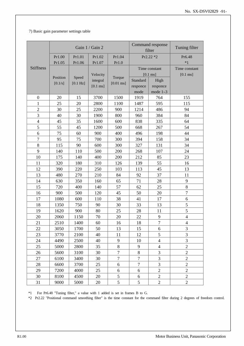
No. SX-DSV02829 -91-
7) Basic gain parameter settings table
Stiffness
Gain 1 / Gain 2 Command response filter Tuning filter
Pr1.00 Pr1.05
Pr1.01 Pr1.06
Pr1.02 Pr1.07
Pr1.04 Pr1.0
Pr2.22 *2 Pr6.48 *1
Position [0.1/s]
Speed [0.1 Hz]
Velocity integral [0.1 ms]
Torque [0.01 ms]
Time constant [0.1 ms]
Time constant [0.1 ms]
Standard responce
mode
High responce mode 1∼3
0 20 15 3700 1500 1919 764 155 1 25 20 2800 1100 1487 595 115 2 30 25 2200 900 1214 486 94 3 40 30 1900 800 960 384 84 4 45 35 1600 600 838 335 64 5 55 45 1200 500 668 267 54 6 75 60 900 400 496 198 44 7 95 75 700 300 394 158 34 8 115 90 600 300 327 131 34 9 140 110 500 200 268 107 24 10 175 140 400 200 212 85 23 11 320 180 310 126 139 55 16 12 390 220 250 103 113 45 13 13 480 270 210 84 92 37 11 14 630 350 160 65 71 28 9 15 720 400 140 57 62 25 8 16 900 500 120 45 50 20 7 17 1080 600 110 38 41 17 6 18 1350 750 90 30 33 13 5 19 1620 900 80 25 28 11 5 20 2060 1150 70 20 22 9 4 21 2510 1400 60 16 18 7 4 22 3050 1700 50 13 15 6 3 23 3770 2100 40 11 12 5 3 24 4490 2500 40 9 10 4 3 25 5000 2800 35 8 9 4 2 26 5600 3100 30 7 8 3 2 27 6100 3400 30 7 7 3 2 28 6600 3700 25 6 7 3 2 29 7200 4000 25 6 6 2 2 30 8100 4500 20 5 6 2 2 31 9000 5000 20 5 5 2 2
*1 For Pr6.48 "Tuning filter," a value with 1 added is set in frames B to G. *2 Pr2.22 "Positional command smoothing filter" is the time constant for the command filter during 2 degrees of freedom control.
R1.00 Motor Business Unit, Panasonic Corporation
No. SX-DSV02829 -92-
5-2 Manual adjusting function
As explained previously, MINAS-A5BL series features the automatic gain tuning function, however, there might be some cases where this automatic gain tuning cannot be adjusted properly depending on the limitation on load conditions. Or you might need to readjust the tuning to obtain the optimum response or stability corresponding to each load. Here we explain this manual gain tuning method by each control mode and function. 1) Block diagram of position control mode (5-2-1) 2) Block diagram of velocity control mode (5-2-2) 3) Block diagram of torque control mode (5-2-3) 4) Gain switching function (5-2-4) 5) Notch filter (5-2-5) 6) Damping control (5-2-6) 7) Feed forward function (5-2-7) 8) Instantaneous velocity observer (5-2-8) 9) Disturbance observer (5-2-9) 10) 3rd gain switching function (5-2-10) 11) Friction torque compensation (5-2-11) 12) 2-stage torque filter (5-2-12) 13) Block Diagram of 2 Degrees of Freedom Mode (Standerd type) (5-2-13) 14) Model type damping filter (5-2-14) 15) Viscous friction compensating gain / Model type damping filter application parameter switching function
(5-2-15)
R1.00 Motor Business Unit, Panasonic Corporation
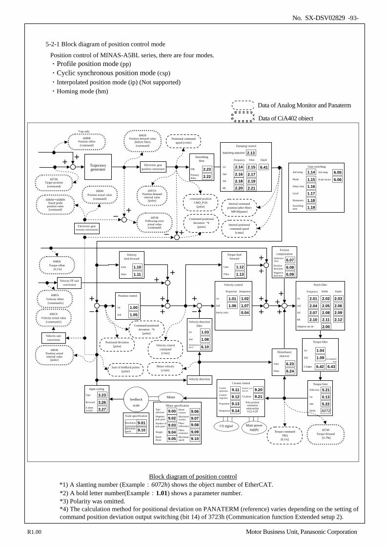
No. SX-DSV02829 -93-
5-2-1 Block diagram of position control mode
Position control of MINAS-A5BL series, there are four modes. ・Profile position mode (pp) ・Cyclic synchronous position mode (csp) ・Interpolated position mode (ip) (Not supported) ・Homing mode (hm)
Velocity feed forward
Gain 1.10 Filter 1.11
Smoothing filter
FIR 2.23 Primary delay 2.22
+
-
Position control
1st 1.00 2nd 1.05
+
+
Damping control
1st 2.14 2nd 2.16 3rd 2.18
2.15
2.17 2.19
4th 2.20 2.21
Switching selection 2.13 Frequency Filter
+
-
Velocity detection
Friction compensation
Additional value 6.07 Positive direction 6.08 Negative direction 6.09
Disturbance observer
Gain 6.23 Filter 6.24
Gain switching
2nd setup 1.14 Mode 1.15 Delay time 1.16 Level 1.17 Hysteresis 1.18 Switching time 1.19
3rd setup 6.05 Scale factor 6.06
Torque limit
Selection 5.21
Torque feed forward
Gain 1.12 Filter 1.13
60F4h Following error
actual value [command]
+ +
+ +
+
6063h Position actual internal value
[pulse]
Velocity detection filter
1st 1.03 2nd 1.08 Instantaneous speed 6.10
Notch filter
2.03
2.06 2.09 2.12
Depth
2.02
2.05 2.08 2.11
Width
1st 2.01 2nd 2.04 3rd 2.07 4th 2.10
Frequency
Adaptive mo de 2.00
Velocity control
1.02
1.07
Proportion Integration
Inertia ratio
1st 1.01 2nd 1.06
0.04
6064h Position actual value
[command] 60BAh~60BDh Touch probe
position value [command]
Trajectory generator
606Ch Velocity actual value
[command/s]
60B1h Velocity offset [command/s]
+ + Velocity FF unit
conversion
60FCh Position demand
internal value [pulse]
60B2h Torque offset
[0.1%]
+
+
MAX 6072
1st 0.13 2nd 5.22
Electronic gear positive conversion
6062h Position demand value
(before filter) [command]
- +
607Ah Target position
[command]
Electronic gear reverse conversion
Positional command speed [r/min]
command position CMD_POS
[pulse]
Positional deviation [pulse] Velocity control
command [r/min]
Motor velocity [r/min]
Internal positional command speed
[r/min]
Internal command position (after filter)
MPOS[pulse]
+ +
60B0h Position offset
[command]
*csp only
Command positional deviation *4
[pulse]
Command positional deviation *4
[pulse]
Sum of feedback pulses [pulse]
- +
6.41
Depth
Torque filter
1st 1.04 2nd 1.09
2 stages 6.42 6.43
At tenuation term
Main power supply
Current control
Current response 9.12 Proportion 9.13
Carrier selection 9.11
Integration 9.14
Magnetic pole detected 9.20 CS phase 9.21
Pole position estimation
relationship 9.22–9.28
CS signal
エンコーダ
feedback
scale
Input setting
Type 3.23 Reversed 3.26 Z phase invalid 3.27
Scale specification
Resolution 9.01 Maximum speed 9.10
Moter
Motor specification
Magnetic pole pitch 9.02 Number of pole pairs 9.03
Type selection 9.00
Weight 9.04 Rated thrust 9.05
Rated current 9.06 Maximum current 9.07
Maximum speed 9.10
Phase inductance 9.08 Phase resistance 9.09 6074h
Torque demand [0.1%]
Torque command TRQ
[0.1%]
Velocity unit conversion
Block diagram of position control
*1) A slanting number (Example:6072h) shows the object number of EtherCAT. *2) A bold letter number(Example:1.01) shows a parameter number. *3) Polarity was omitted. *4) The calculation method for positional deviation on PANATERM (reference) varies depending on the setting of command position deviation output switching (bit 14) of 3723h (Communication function Extended setup 2).
Data of CiA402 object
Data of Analog Monitor and Panaterm
R1.00 Motor Business Unit, Panasonic Corporation
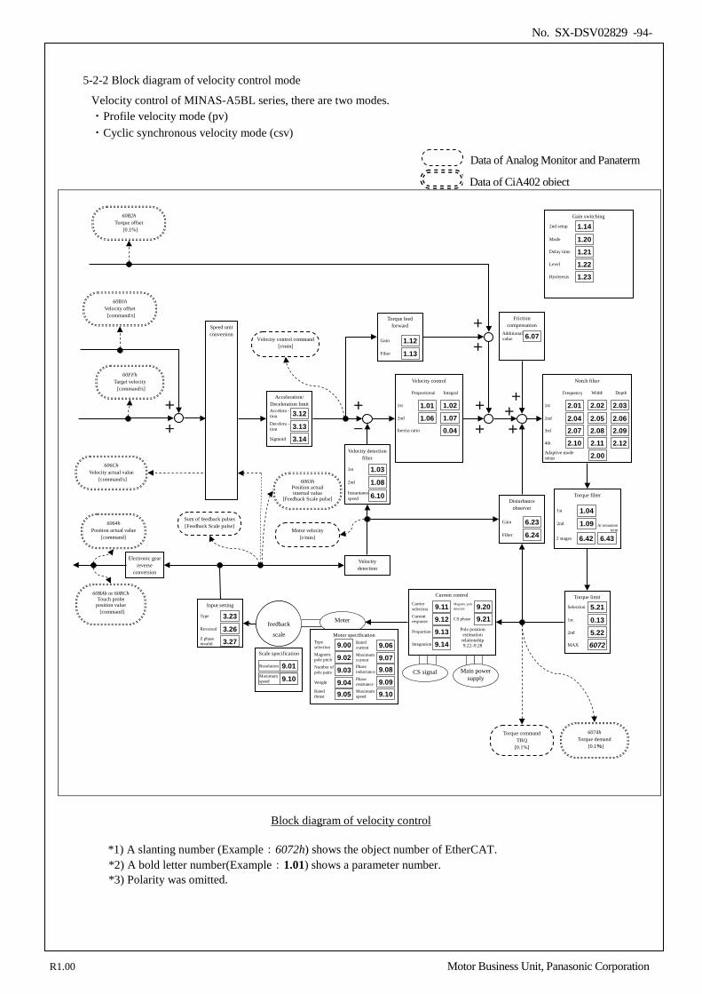
No. SX-DSV02829 -94-
5-2-2 Block diagram of velocity control mode
Velocity control of MINAS-A5BL series, there are two modes. ・Profile velocity mode (pv) ・Cyclic synchronous velocity mode (csv)
Velocity detection
+
-
Friction compensation
Additional value 6.07
Disturbance observer
Gain 6.23 Filter 6.24
Gain switching
2nd setup 1.14 Mode 1.20 Delay time 1.21 Level 1.22 Hysteresis 1.23
Torque feed forward
Gain 1.12 Filter 1.13
+ +
+ +
+
6063h Position actual internal value
[Feedback Scale pulse]
Velocity detection filter
1st 1.03 2nd 1.08 Instantaneous speed 6.10
Notch filter
2.03
2.06 2.09 2.12
Depth
2.02
2.05 2.08 2.11
Width
1st 2.01 2nd 2.04 3rd 2.07 4th 2.10
Frequency
Adaptive mode setup 2.00
Velocity control
1.02
1.07
Proportional Integral
Inertia ratio
1st 1.01 2nd 1.06
0.04
Acceleration/ Deceleration limit Accelera - tion 3.12 Decelera - tion 3.13 Sigmoid 3.14
Speed unit conversion
60FFh Target velocity [command/s]
6074h Torque demand
[0.1%]
6064h Position actual value
[command]
60BAh or 60BCh Touch probe
position value [command]
606Ch Velocity actual value
[command/s]
60B2h Torque offset
[0.1%]
+
+
60B1h Velocity offset [command/s]
+
+
Torque limit
Selection 5.21 1st 0.13 2nd 5.22 MAX 6072
Electronic gear reverse
conversion
Velocity control command [r/min]
Motor velocity [r/min]
Torque command TRQ
[0.1%]
Sum of feedback pulses [Feedback Scale pulse]
Torque filter
1st 1.04 2nd 1.09
2 stages 6.42 6.43
At tenuation term
Main power supply
Current control
Current response 9.12 Proportion 9.13
Carrier selection 9.11
Integration 9.14
Magnetic pole detected 9.20 CS phase 9.21
Pole position estimation
relationship 9.22–9.28
CS signal
エンコーダ
feedback
scale
Input setting
Type 3.23 Reversed 3.26 Z phase invalid 3.27
Scale specification
Resolution 9.01 Maximum speed 9.10
Moter
Motor specification
Magnetic pole pitch 9.02 Number of pole pairs 9.03
Type selection 9.00
Weight 9.04 Rated thrust 9.05
Rated current 9.06 Maximum current 9.07
Maximum speed 9.10
Phase inductance 9.08 Phase resistance 9.09
Block diagram of velocity control *1) A slanting number (Example:6072h) shows the object number of EtherCAT. *2) A bold letter number(Example:1.01) shows a parameter number. *3) Polarity was omitted.
Data of CiA402 object
Data of Analog Monitor and Panaterm
R1.00 Motor Business Unit, Panasonic Corporation
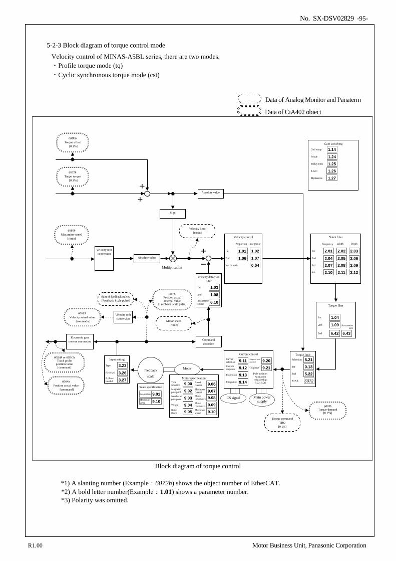
No. SX-DSV02829 -95-
5-2-3 Block diagram of torque control mode
Velocity control of MINAS-A5BL series, there are two modes. ・Profile torque mode (tq) ・Cyclic synchronous torque mode (cst)
+
-
Command detection
Gain switching
2nd setup 1.14 Mode 1.24 Delay time 1.25 Level 1.26 Hysteresis 1.27
Velocity detection filter
1st 1.03 2nd 1.08 Instantaneous speed 6.10
Notch filter
2.03
2.06 2.09 2.12
Depth
2.02
2.05 2.08 2.11
Width
1st 2.01 2nd 2.04 3rd 2.07 4th 2.10
Frequency
Velocity control
1.02
1.07
Proportion Integration
Inertia ratio
1st 1.01 2nd 1.06
0.04
Sign
Absolute value
Torque limit Selection 5.21
MAX 6072 6064h Position actual value
[command]
60BAh or 60BCh Touch probe
position value [command]
Electronic gear reverse conversion
6063h Position actual internal value
[Feedback Scale pulse]
606Ch Velocity actual value
[commad/s]
6074h Torque demand
[0.1%]
60B2h Torque offset
[0.1%]
6080h Max motor speed
[r/min]
Velocity unit conversion
Absolute value
Multiplication
+
+
6071h Target torque
[0.1%]
1st 0.13 2nd 5.22
Motor speed [r/min]
Velocity limit [r/min]
Torque command TRQ
[0.1%]
Sum of feedback pulses [Feedback Scale pulse]
Torque filter
1st 1.04 2nd 1.09
2nd 6.42 6.43
At tenuation term
Main power supply
Current control
Current response 9.12 Proportion 9.13
Carrier selection 9.11
Integration 9.14
Magnetic pole detected 9.20 CS phase 9.21
Pole position estimation
relationship 9.22–9.28
CS signal
エンコーダ
feedback
scale
Input setting
Type 3.23 Reversed 3.26 Z phase invalid 3.27
Scale specification
Resolution 9.01 Maximum speed 9.10
Moter
Motor specification
Magnetic pole pitch 9.02 Number of pole pairs 9.03
Type selection 9.00
Weight 9.04 Rated thrust 9.05
Rated current 9.06 Maximum current 9.07
Maximum speed 9.10
Phase inductance 9.08 Phase resistance 9.09
Velocity unit conversion
Block diagram of torque control
*1) A slanting number (Example:6072h) shows the object number of EtherCAT. *2) A bold letter number(Example:1.01) shows a parameter number. *3) Polarity was omitted.
Data of CiA402 object
Data of Analog Monitor and Panaterm
R1.00 Motor Business Unit, Panasonic Corporation
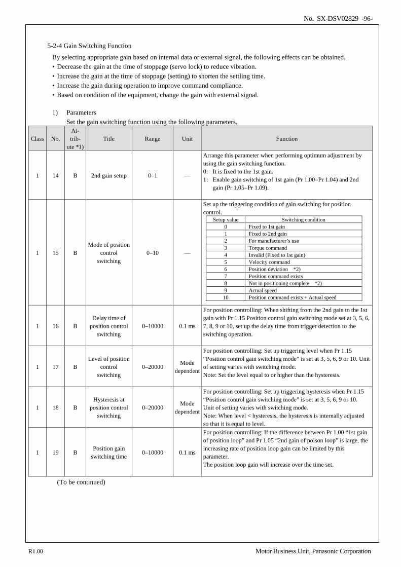
No. SX-DSV02829 -96-
5-2-4 Gain Switching Function
By selecting appropriate gain based on internal data or external signal, the following effects can be obtained. • Decrease the gain at the time of stoppage (servo lock) to reduce vibration. • Increase the gain at the time of stoppage (setting) to shorten the settling time. • Increase the gain during operation to improve command compliance. • Based on condition of the equipment, change the gain with external signal.
1) Parameters
Set the gain switching function using the following parameters.
Class No. At- trib-
ute *1) Title Range Unit Function
1 14 B 2nd gain setup 0–1 —
Arrange this parameter when performing optimum adjustment by using the gain switching function. 0: It is fixed to the 1st gain. 1: Enable gain switching of 1st gain (Pr 1.00−Pr 1.04) and 2nd
gain (Pr 1.05−Pr 1.09).
1 15 B Mode of position
control switching
0–10 —
Set up the triggering condition of gain switching for position control.
Setup value Switching condition 0 Fixed to 1st gain 1 Fixed to 2nd gain 2 For manufacturer’s use 3 Torque command 4 Invalid (Fixed to 1st gain) 5 Velocity command 6 Position deviation *2) 7 Position command exists 8 Not in positioning complete *2) 9 Actual speed
10 Position command exists + Actual speed
1 16 B Delay time of
position control switching
0–10000 0.1 ms
For position controlling: When shifting from the 2nd gain to the 1st gain with Pr 1.15 Position control gain switching mode set at 3, 5, 6, 7, 8, 9 or 10, set up the delay time from trigger detection to the switching operation.
1 17 B Level of position
control switching
0–20000 Mode
dependent
For position controlling: Set up triggering level when Pr 1.15 “Position control gain switching mode” is set at 3, 5, 6, 9 or 10. Unit of setting varies with switching mode. Note: Set the level equal to or higher than the hysteresis.
1 18 B Hysteresis at
position control switching
0–20000 Mode
dependent
For position controlling: Set up triggering hysteresis when Pr 1.15 “Position control gain switching mode” is set at 3, 5, 6, 9 or 10. Unit of setting varies with switching mode. Note: When level < hysteresis, the hysteresis is internally adjusted so that it is equal to level.
1 19 B Position gain
switching time 0–10000 0.1 ms
For position controlling: If the difference between Pr 1.00 “1st gain of position loop” and Pr 1.05 “2nd gain of poison loop” is large, the increasing rate of position loop gain can be limited by this parameter. The position loop gain will increase over the time set.
(To be continued)
R1.00 Motor Business Unit, Panasonic Corporation
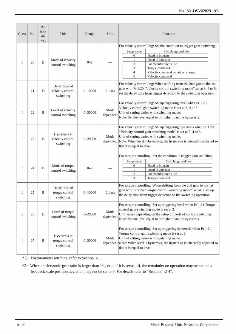
No. SX-DSV02829 -97-
Class No.
At- trib- ute *1)
Title Range Unit Function
1 20 B Mode of velocity control switching
0–5 —
For velocity controlling: Set the condition to trigger gain switching. Setup value Switching condition
0 Fixed to 1st gain 1 Fixed to 2nd gain 2 For manufacturer’s use 3 Torque command 4 Velocity command variation is larger. 5 Velocity command
1 21 B Delay time of
velocity control switching
0–10000 0.1 ms
For velocity controlling: When shifting from the 2nd gain to the 1st gain with Pr 1.20 “Velocity control switching mode” set at 3, 4 or 5, set the delay time from trigger detection to the switching operation.
1 22 B Level of velocity control switching
0–20000 Mode
dependent
For velocity controlling: Set up triggering level when Pr 1.20 Velocity control gain switching mode is set at 3, 4 or 5. Unit of setting varies with switching mode. Note: Set the level equal to or higher than the hysteresis.
1 23 B Hysteresis at
velocity control switching
0–20000 Mode
dependent
For velocity controlling: Set up triggering hysteresis when Pr 1.20 “Velocity control gain switching mode” is set at 3, 4 or 5. Unit of setting varies with switching mode. Note: When level < hysteresis, the hysteresis is internally adjusted so that it is equal to level.
1 24 B Mode of torque
control switching 0–3 —
For torque controlling: Set the condition to trigger gain switching Setup value Switching condition
0 Fixed to 1st gain 1 Fixed to 2nd gain 2 For manufacturer’s use 3 Torque command
1 25 B Delay time of torque control
switching 0–10000 0.1 ms
For torque controlling: When shifting from the 2nd gain to the 1st gain with Pr 1.24 “Torque control switching mode” set at 3, set up the delay time from trigger detection to the switching operation.
1 26 B Level of torque
control switching 0–20000
Mode dependent
For torque controlling: Set up triggering level when Pr 1.24 Torque control gain switching mode is set at 3. Unit varies depending on the setup of mode of control switching. Note: Set the level equal to or higher than the hysteresis.
1 27 B Hysteresis at
torque control switching
0–20000 Mode
dependent
For torque controlling: Set up triggering hysteresis when Pr 1.24 Torque control gain switching mode is set at 3. Unit of setting varies with switching mode. Note: When level < hysteresis, the hysteresis is internally adjusted so that it is equal to level.
*1) For parameter attribute, refer to Section 9-1.
*2)When an electronic gear ratio is larger than 1/1, even if it is servo-off, the remainder on operation may occur and a feedback scale position deviation may not be set to 0. For details refer to “Section 4-2-4”.
R1.00 Motor Business Unit, Panasonic Corporation
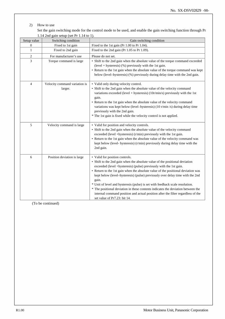
No. SX-DSV02829 -98-
2) How to use
Set the gain switching mode for the control mode to be used, and enable the gain switching function through Pr 1.14 2nd gain setup (set Pr 1.14 to 1).
Setup value Switching condition Gain switching condition 0 Fixed to 1st gain Fixed to the 1st gain (Pr 1.00 to Pr 1.04). 1 Fixed to 2nd gain Fixed to the 2nd gain (Pr 1.05 to Pr 1.09).
2 For manufacturer’s use Please do not set. 3 Torque command is large • Shift to the 2nd gain when the absolute value of the torque command exceeded
(level + hysteresis) (%) previously with the 1st gain. • Return to the 1st gain when the absolute value of the torque command was kept
below (level–hysteresis) (%) previously during delay time with the 2nd gain.
4 Velocity command variation is larger.
• Valid only during velocity control. • Shift to the 2nd gain when the absolute value of the velocity command
variations exceeded (level + hysteresis) (10r/min/s) previously with the 1st gain.
• Return to the 1st gain when the absolute value of the velocity command variations was kept below (level–hysteresis) (10 r/min /s) during delay time previously with the 2nd gain.
* The 1st gain is fixed while the velocity control is not applied.
5 Velocity command is large • Valid for position and velocity controls. • Shift to the 2nd gain when the absolute value of the velocity command
exceeded (level +hysteresis) (r/min) previously with the 1st gain. • Return to the 1st gain when the absolute value of the velocity command was
kept below (level- hysteresis) (r/min) previously during delay time with the 2nd gain.
6 Position deviation is large • Valid for position controls.
• Shift to the 2nd gain when the absolute value of the positional deviation exceeded (level +hysteresis) (pulse) previously with the 1st gain.
• Return to the 1st gain when the absolute value of the positional deviation was kept below (level–hysteresis) (pulse) previously over delay time with the 2nd gain.
* Unit of level and hysteresis (pulse) is set with feedback scale resolution. * The positional deviation in these contents indicates the deviation between the
internal command position and actual position after the filter regardless of the set value of Pr7.23: bit 14.
(To be continued)
R1.00 Motor Business Unit, Panasonic Corporation
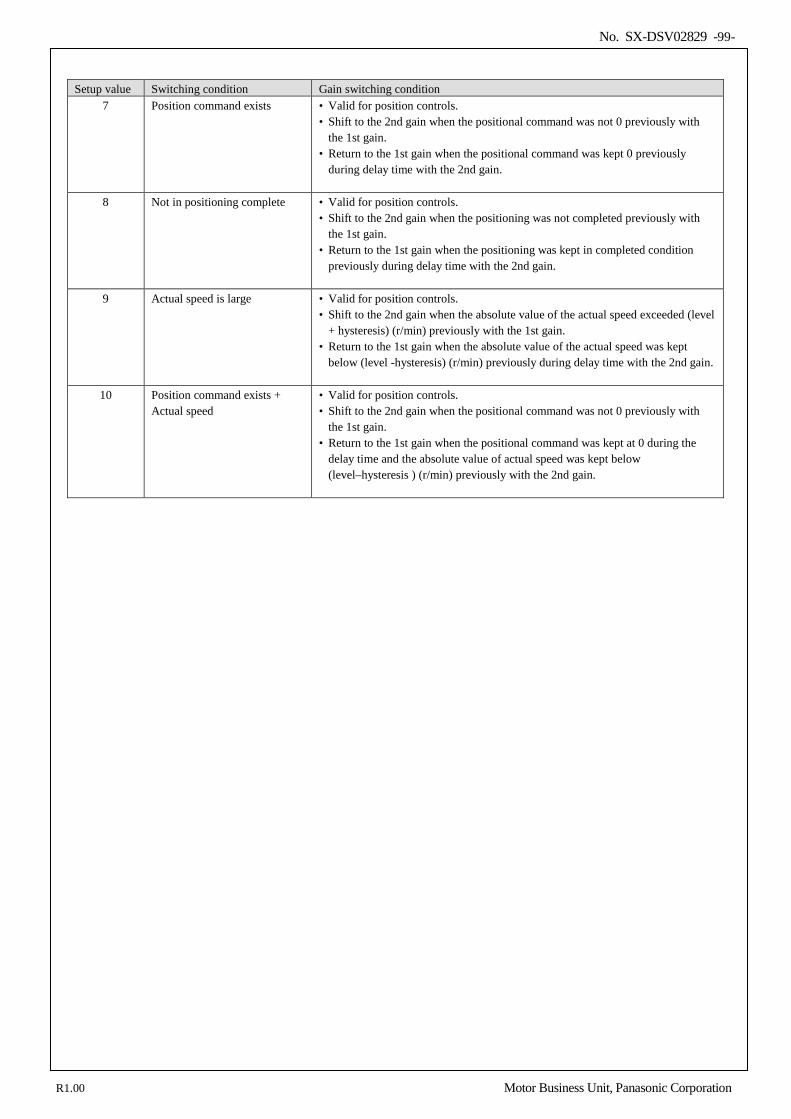
No. SX-DSV02829 -99-
Setup value Switching condition Gain switching condition
7 Position command exists • Valid for position controls. • Shift to the 2nd gain when the positional command was not 0 previously with
the 1st gain. • Return to the 1st gain when the positional command was kept 0 previously
during delay time with the 2nd gain.
8 Not in positioning complete • Valid for position controls. • Shift to the 2nd gain when the positioning was not completed previously with
the 1st gain. • Return to the 1st gain when the positioning was kept in completed condition
previously during delay time with the 2nd gain.
9 Actual speed is large • Valid for position controls. • Shift to the 2nd gain when the absolute value of the actual speed exceeded (level
+ hysteresis) (r/min) previously with the 1st gain. • Return to the 1st gain when the absolute value of the actual speed was kept
below (level -hysteresis) (r/min) previously during delay time with the 2nd gain.
10 Position command exists + Actual speed
• Valid for position controls. • Shift to the 2nd gain when the positional command was not 0 previously with
the 1st gain. • Return to the 1st gain when the positional command was kept at 0 during the
delay time and the absolute value of actual speed was kept below (level–hysteresis ) (r/min) previously with the 2nd gain.
R1.00 Motor Business Unit, Panasonic Corporation
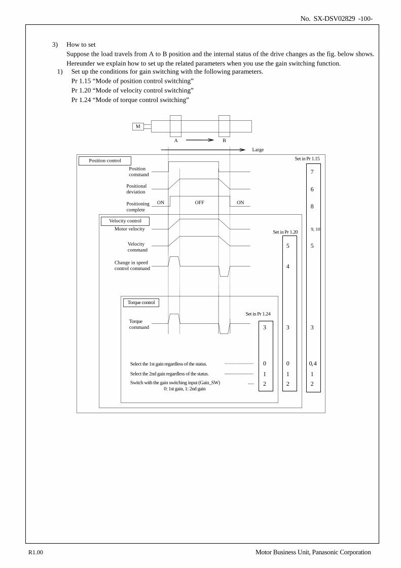
No. SX-DSV02829 -100-
3) How to set
Suppose the load travels from A to B position and the internal status of the drive changes as the fig. below shows. Hereunder we explain how to set up the related parameters when you use the gain switching function.
1) Set up the conditions for gain switching with the following parameters. Pr 1.15 “Mode of position control switching” Pr 1.20 “Mode of velocity control switching” Pr 1.24 “Mode of torque control switching”
Select the 1st gain regardless of the status.
Select the 2nd gain regardless of the status.
Switch with the gain switching input (Gain_SW) 0: 1st gain, 1: 2nd gain
2 1
0, 4
3
9, 10
8
6
7
2 1
0
3
4
2 1
0
3
Positioning complete
OFF ON ON
Positional deviation
Set in Pr 1.24
Set in Pr 1.20
Set in Pr 1.15
Torque control
Position control
Velocity control
Position command
Change in speed control command
Motor velocity
Torque command
Velocity command
5 5
M
A B
Large
R1.00 Motor Business Unit, Panasonic Corporation
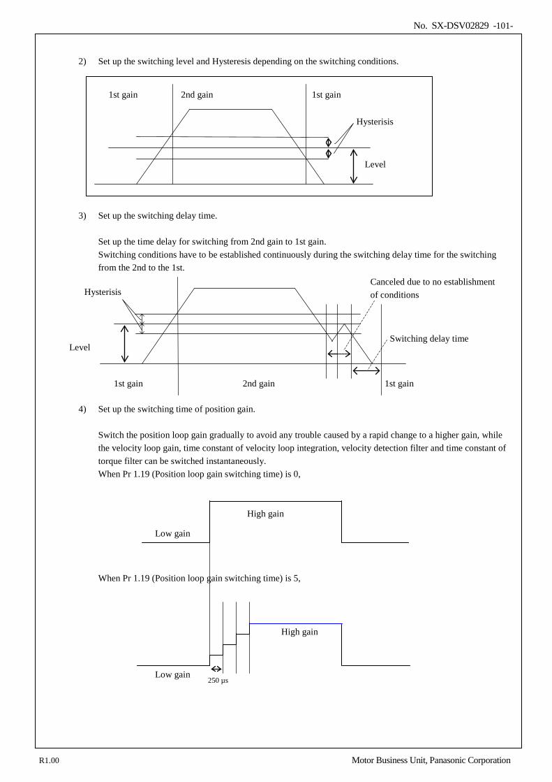
No. SX-DSV02829 -101-
2) Set up the switching level and Hysteresis depending on the switching conditions.
3) Set up the switching delay time.
Set up the time delay for switching from 2nd gain to 1st gain. Switching conditions have to be established continuously during the switching delay time for the switching from the 2nd to the 1st.
4) Set up the switching time of position gain.
Switch the position loop gain gradually to avoid any trouble caused by a rapid change to a higher gain, while the velocity loop gain, time constant of velocity loop integration, velocity detection filter and time constant of torque filter can be switched instantaneously. When Pr 1.19 (Position loop gain switching time) is 0,
When Pr 1.19 (Position loop gain switching time) is 5,
1st gain 2nd gain 1st gain
Level
Hysterisis
1st gain
2nd gain
1st gain
Level
Canceled due to no establishment of conditions Hysterisis
Switching delay time
High gain
Low gain
250 µs
High gain
Low gain
R1.00 Motor Business Unit, Panasonic Corporation
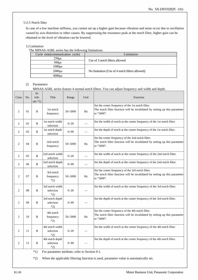
No. SX-DSV02829 -102-
5-2-5 Notch filter
In case of a low machine stiffness, you cannot set up a higher gain because vibration and noise occur due to oscillation caused by axis distortion or other causes. By suppressing the resonance peak at the notch filter, higher gain can be obtained or the level of vibration can be lowered. 1) Limitation
The MINAS-A5BL series has the following limitations. Cycle time(communication cycle) Limitation
250μs Use of 3 notch filters allowed 500μs 1000μs
No limitation (Use of 4 notch filters allowed) 2000μs 4000μs
2) Parameters MINAS-A5BL series feature 4 normal notch filters. You can adjust frequency and width and depth.
Class No. At- trib-
ute *1) Title Range Unit Function
2 01 B 1st notch frequency
50–5000 Hz
Set the center frequency of the 1st notch filter. The notch filter function will be invalidated by setting up this parameter to “5000”.
2 02 B 1st notch width
selection 0–20 —
Set the width of notch at the center frequency of the 1st notch filter.
2 03 B 1st notch depth
selection 0–99 —
Set the depth of notch at the center frequency of the 1st notch filter.
2 04 B 2nd notch frequency
50–5000 Hz
Set the center frequency of the 2nd notch filter. The notch filter function will be invalidated by setting up this parameter to “5000”.
2 05 B 2nd notch width
selection 0–20 —
Set the width of notch at the center frequency of the 2nd notch filter.
2 06 B 2nd notch depth
selection 0–99 —
Set the depth of notch at the center frequency of the 2nd notch filter.
2 07 B 3rd notch frequency
*2) 50–5000 Hz
Set the center frequency of the 3rd notch filter. The notch filter function will be invalidated by setting up this parameter to “5000”.
2 08 B 3rd notch width
selection *2)
0–20 — Set the width of notch at the center frequency of the 3rd notch filter.
2 09 B 3rd notch depth
selection *2)
0–99 — Set the depth of notch at the center frequency of the 3rd notch filter.
2 10 B 4th notch frequency
*2) 50–5000 Hz
Set the center frequency of the 4th notch filter. The notch filter function will be invalidated by setting up this parameter to “5000”.
2 11 B 4th notch width
selection *2)
0–20 — Set the width of notch at the center frequency of the 4th notch filter.
2 12 B 4th notch depth
selection *2)
0–99 — Set the depth of notch at the center frequency of the 4th notch filter.
*1) For parameter attribute, refer to Section 9-1.
*2) When the applicable filtering function is used, parameter value is automatically set.
R1.00 Motor Business Unit, Panasonic Corporation
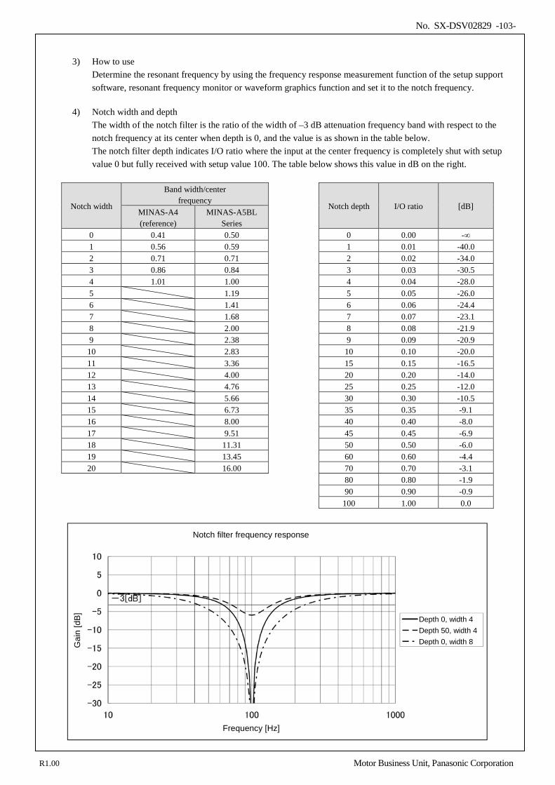
No. SX-DSV02829 -103-
3) How to use
Determine the resonant frequency by using the frequency response measurement function of the setup support software, resonant frequency monitor or waveform graphics function and set it to the notch frequency.
4) Notch width and depth
The width of the notch filter is the ratio of the width of –3 dB attenuation frequency band with respect to the notch frequency at its center when depth is 0, and the value is as shown in the table below. The notch filter depth indicates I/O ratio where the input at the center frequency is completely shut with setup value 0 but fully received with setup value 100. The table below shows this value in dB on the right.
Notch width
Band width/center frequency
Notch depth I/O ratio [dB]
MINAS-A4 (reference)
MINAS-A5BL Series
0 0.41 0.50 0 0.00 -∞ 1 0.56 0.59 1 0.01 -40.0 2 0.71 0.71 2 0.02 -34.0 3 0.86 0.84 3 0.03 -30.5 4 1.01 1.00 4 0.04 -28.0 5 1.19 5 0.05 -26.0 6 1.41 6 0.06 -24.4 7 1.68 7 0.07 -23.1 8 2.00 8 0.08 -21.9 9 2.38 9 0.09 -20.9 10 2.83 10 0.10 -20.0 11 3.36 15 0.15 -16.5 12 4.00 20 0.20 -14.0 13 4.76 25 0.25 -12.0 14 5.66 30 0.30 -10.5 15 6.73 35 0.35 -9.1 16 8.00 40 0.40 -8.0 17 9.51 45 0.45 -6.9 18 11.31 50 0.50 -6.0 19 13.45 60 0.60 -4.4 20 16.00 70 0.70 -3.1
80 0.80 -1.9 90 0.90 -0.9 100 1.00 0.0
Frequency [Hz]
Gai
n [d
B]
Depth 0, width 4 Depth 50, width 4 Depth 0, width 8
Notch filter frequency response
R1.00 Motor Business Unit, Panasonic Corporation
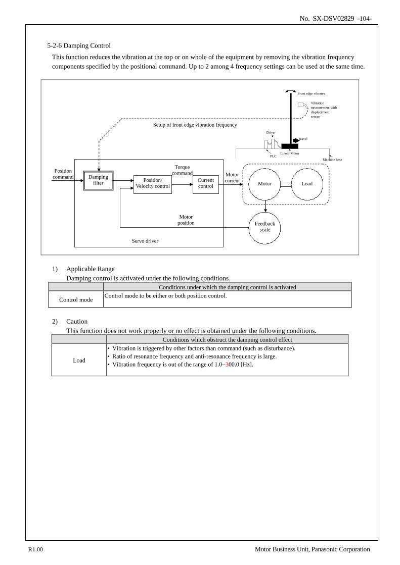
No. SX-DSV02829 -104-
5-2-6 Damping Control
This function reduces the vibration at the top or on whole of the equipment by removing the vibration frequency components specified by the positional command. Up to 2 among 4 frequency settings can be used at the same time.
Current control
Position/ Velocity control
Position command
Torque command Motor
current Motor
Feedback scale
Servo driver
Motor position
Load Damping
filter
Setup of front edge vibration frequency
Linear Motor
travel
Front edge vibrates
Machine base
Driver
PLC
Vibration measurement with displacement sensor
1) Applicable Range Damping control is activated under the following conditions.
Conditions under which the damping control is activated
Control mode Control mode to be either or both position control.
2) Caution
This function does not work properly or no effect is obtained under the following conditions. Conditions which obstruct the damping control effect
Load
• Vibration is triggered by other factors than command (such as disturbance). • Ratio of resonance frequency and anti-resonance frequency is large. • Vibration frequency is out of the range of 1.0−300.0 [Hz].
R1.00 Motor Business Unit, Panasonic Corporation
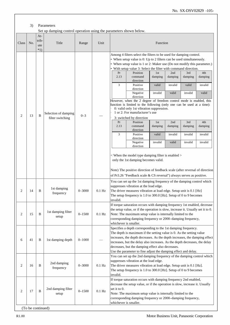
No. SX-DSV02829 -105-
3) Parameters
Set up damping control operation using the parameters shown below.
Class No.
At- trib- ute *1)
Title Range Unit Function
2 13 B Selection of damping
filter switching 0–3 —
Among 4 filters select the filters to be used for damping control. • When setup value is 0: Up to 2 filters can be used simultaneously. • When setup value is 1 or 2: Maker use (Do not modify this parameter.) • With setup value 3: Select the filter with command direction.
Pr 2.13
Position command direction
1st damping
2nd damping
3rd damping
4th damping
3 Positive direction
valid invalid valid invalid
Negative direction
invalid valid invalid valid
However, when the 2 degree of freedom control mode is enabled, this function is limited to the following (only one can be used at a time): 0: valid only 1st vibration suppression. 1 or 2: For manufacturer’s use 3: switched by direction
Pr 2.13
Position command direction
1st damping
2nd damping
3rd damping
4th damping
3 Positive direction
valid invalid invalid invalid
Negative direction
invalid valid invalid invalid
< When the model type damping filter is enabled >
only the 1st damping becomes valid.
Note) The positive direction of feedback scale (after reversal of direction of Pr3.26 "Feedback scale & CS reversal") always serves as positive.
2 14 B 1st damping frequency
0–3000 0.1 Hz
You can set up the 1st damping frequency of the damping control which suppresses vibration at the load edge. The driver measures vibration at load edge. Setup unit is 0.1 [Hz] The setup frequency is 1.0 to 300.0 [Hz]. Setup of 0 to 9 becomes invalid.
2 15 B 1st damping filter
setup 0–1500 0.1 Hz
If torque saturation occurs with damping frequency 1st enabled, decrease the setup value, or if the operation is slow, increase it. Usually set it to 0. Note: The maximum setup value is internally limited to the corresponding damping frequency or 2000–damping frequency, whichever is smaller.
6 41 B 1st damping depth 0−1000 —
Specifies a depth corresponding to the 1st damping frequency. The depth is maximum if the setting value is 0. As the setting value increases, the depth decreases. As the depth increases, the damping effect increases, but the delay also increases. As the depth decreases, the delay decreases, but the damping effect also decreases. Use the parameter to fine adjust the damping effect and delay.
2 16 B 2nd damping
frequency 0–3000 0.1 Hz
You can set up the 2nd damping frequency of the damping control which suppresses vibration at the load edge. The driver measures vibration at load edge. Setup unit is 0.1 [Hz]. The setup frequency is 1.0 to 300.0 [Hz]. Setup of 0 to 9 becomes invalid.
2 17 B 2nd damping filter
setup 0–1500 0.1 Hz
If torque saturation occurs with damping frequency 2nd enabled, decrease the setup value, or if the operation is slow, increase it. Usually set it to 0. Note: The maximum setup value is internally limited to the corresponding damping frequency or 2000–damping frequency, whichever is smaller.
(To be continued)
R1.00 Motor Business Unit, Panasonic Corporation
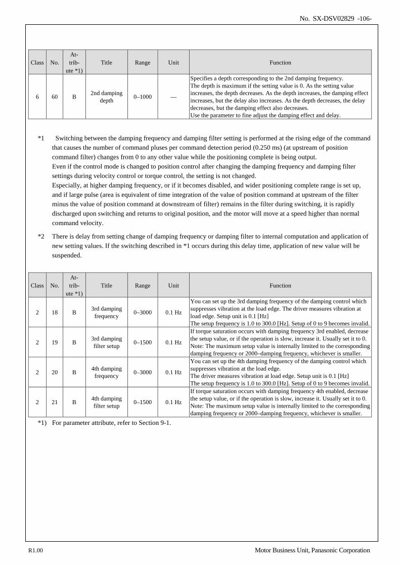
No. SX-DSV02829 -106-
Class No. At- trib-
ute *1) Title Range Unit Function
6 60 B 2nd damping depth 0–1000 —
Specifies a depth corresponding to the 2nd damping frequency. The depth is maximum if the setting value is 0. As the setting value increases, the depth decreases. As the depth increases, the damping effect increases, but the delay also increases. As the depth decreases, the delay decreases, but the damping effect also decreases. Use the parameter to fine adjust the damping effect and delay.
*1 Switching between the damping frequency and damping filter setting is performed at the rising edge of the command that causes the number of command pluses per command detection period (0.250 ms) (at upstream of position command filter) changes from 0 to any other value while the positioning complete is being output. Even if the control mode is changed to position control after changing the damping frequency and damping filter settings during velocity control or torque control, the setting is not changed. Especially, at higher damping frequency, or if it becomes disabled, and wider positioning complete range is set up, and if large pulse (area is equivalent of time integration of the value of position command at upstream of the filter minus the value of position command at downstream of filter) remains in the filter during switching, it is rapidly discharged upon switching and returns to original position, and the motor will move at a speed higher than normal command velocity.
*2 There is delay from setting change of damping frequency or damping filter to internal computation and application of new setting values. If the switching described in *1 occurs during this delay time, application of new value will be suspended.
Class No. At- trib-
ute *1) Title Range Unit Function
2 18 B 3rd damping frequency 0–3000 0.1 Hz
You can set up the 3rd damping frequency of the damping control which suppresses vibration at the load edge. The driver measures vibration at load edge. Setup unit is 0.1 [Hz] The setup frequency is 1.0 to 300.0 [Hz]. Setup of 0 to 9 becomes invalid.
2 19 B 3rd damping filter setup 0–1500 0.1 Hz
If torque saturation occurs with damping frequency 3rd enabled, decrease the setup value, or if the operation is slow, increase it. Usually set it to 0. Note: The maximum setup value is internally limited to the corresponding damping frequency or 2000–damping frequency, whichever is smaller.
2 20 B 4th damping frequency 0–3000 0.1 Hz
You can set up the 4th damping frequency of the damping control which suppresses vibration at the load edge. The driver measures vibration at load edge. Setup unit is 0.1 [Hz] The setup frequency is 1.0 to 300.0 [Hz]. Setup of 0 to 9 becomes invalid.
2 21 B 4th damping filter setup 0–1500 0.1 Hz
If torque saturation occurs with damping frequency 4th enabled, decrease the setup value, or if the operation is slow, increase it. Usually set it to 0. Note: The maximum setup value is internally limited to the corresponding damping frequency or 2000–damping frequency, whichever is smaller.
*1) For parameter attribute, refer to Section 9-1.
R1.00 Motor Business Unit, Panasonic Corporation
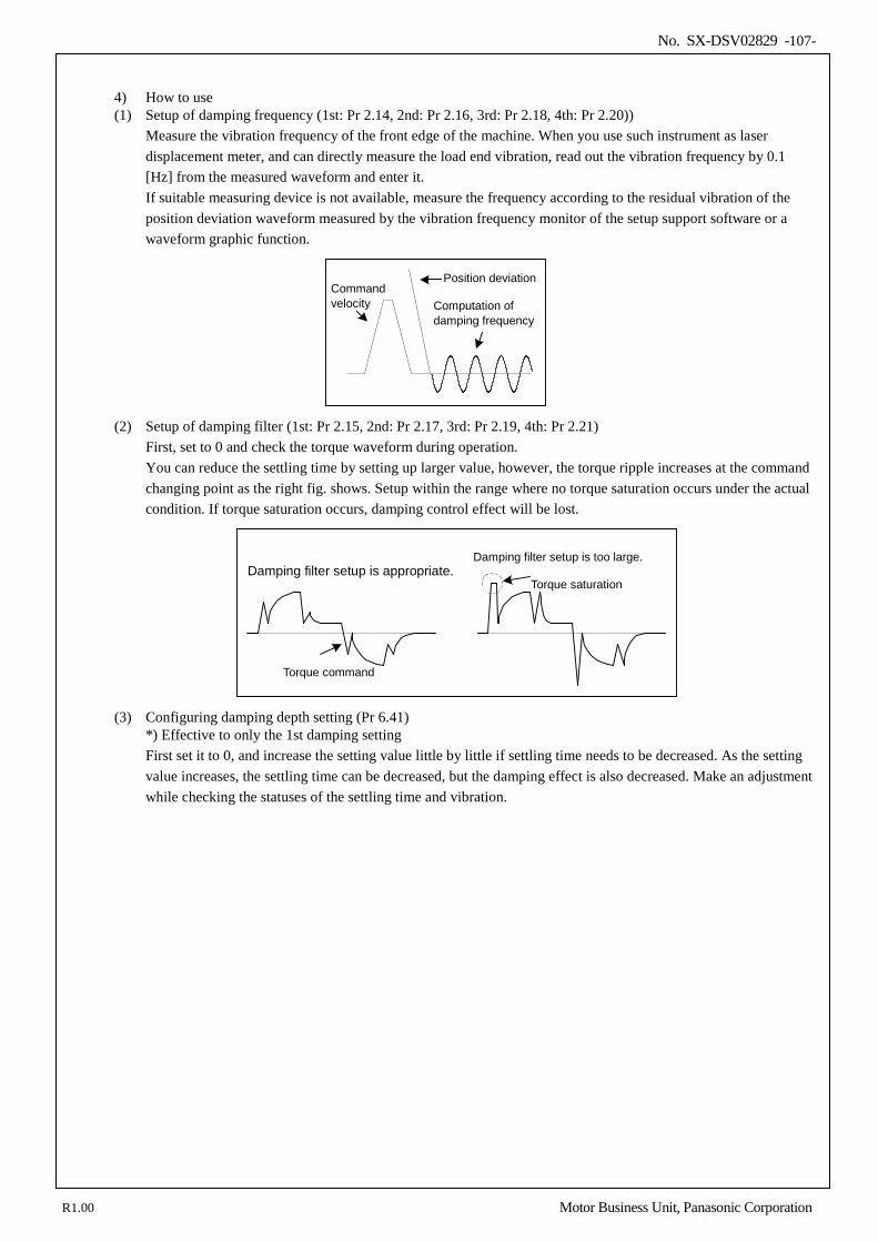
No. SX-DSV02829 -107-
4) How to use (1) Setup of damping frequency (1st: Pr 2.14, 2nd: Pr 2.16, 3rd: Pr 2.18, 4th: Pr 2.20))
Measure the vibration frequency of the front edge of the machine. When you use such instrument as laser displacement meter, and can directly measure the load end vibration, read out the vibration frequency by 0.1 [Hz] from the measured waveform and enter it. If suitable measuring device is not available, measure the frequency according to the residual vibration of the position deviation waveform measured by the vibration frequency monitor of the setup support software or a waveform graphic function.
(2) Setup of damping filter (1st: Pr 2.15, 2nd: Pr 2.17, 3rd: Pr 2.19, 4th: Pr 2.21)
First, set to 0 and check the torque waveform during operation. You can reduce the settling time by setting up larger value, however, the torque ripple increases at the command changing point as the right fig. shows. Setup within the range where no torque saturation occurs under the actual condition. If torque saturation occurs, damping control effect will be lost.
Torque command
Damping filter setup is appropriate. Damping filter setup is too large.
Torque saturation
(3) Configuring damping depth setting (Pr 6.41) *) Effective to only the 1st damping setting First set it to 0, and increase the setting value little by little if settling time needs to be decreased. As the setting value increases, the settling time can be decreased, but the damping effect is also decreased. Make an adjustment while checking the statuses of the settling time and vibration.
指令速度
位置偏差
振動周波数を算出
Position deviation
Computation of damping frequency
Command velocity
R1.00 Motor Business Unit, Panasonic Corporation
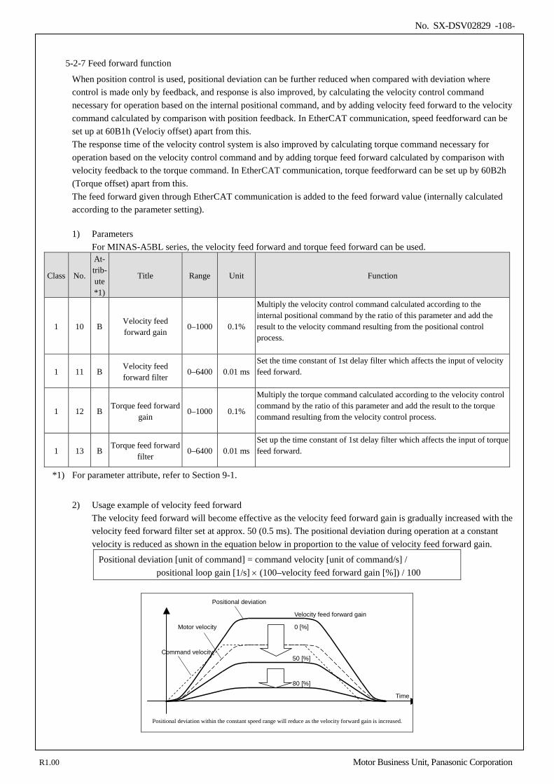
No. SX-DSV02829 -108-
5-2-7 Feed forward function
When position control is used, positional deviation can be further reduced when compared with deviation where control is made only by feedback, and response is also improved, by calculating the velocity control command necessary for operation based on the internal positional command, and by adding velocity feed forward to the velocity command calculated by comparison with position feedback. In EtherCAT communication, speed feedforward can be set up at 60B1h (Velociy offset) apart from this. The response time of the velocity control system is also improved by calculating torque command necessary for operation based on the velocity control command and by adding torque feed forward calculated by comparison with velocity feedback to the torque command. In EtherCAT communication, torque feedforward can be set up by 60B2h (Torque offset) apart from this. The feed forward given through EtherCAT communication is added to the feed forward value (internally calculated according to the parameter setting).
1) Parameters
For MINAS-A5BL series, the velocity feed forward and torque feed forward can be used.
Class No.
At- trib- ute *1)
Title Range Unit Function
1 10 B Velocity feed forward gain
0–1000 0.1%
Multiply the velocity control command calculated according to the internal positional command by the ratio of this parameter and add the result to the velocity command resulting from the positional control process.
1 11 B Velocity feed forward filter
0–6400 0.01 ms Set the time constant of 1st delay filter which affects the input of velocity feed forward.
1 12 B Torque feed forward
gain 0–1000 0.1%
Multiply the torque command calculated according to the velocity control command by the ratio of this parameter and add the result to the torque command resulting from the velocity control process.
1 13 B Torque feed forward
filter 0–6400 0.01 ms
Set up the time constant of 1st delay filter which affects the input of torque feed forward.
*1) For parameter attribute, refer to Section 9-1.
2) Usage example of velocity feed forward
The velocity feed forward will become effective as the velocity feed forward gain is gradually increased with the velocity feed forward filter set at approx. 50 (0.5 ms). The positional deviation during operation at a constant velocity is reduced as shown in the equation below in proportion to the value of velocity feed forward gain.
Positional deviation [unit of command] = command velocity [unit of command/s] / positional loop gain [1/s] × (100–velocity feed forward gain [%]) / 100
Command velocity
Motor velocity
Positional deviation
Positional deviation within the constant speed range will reduce as the velocity forward gain is increased.
Velocity feed forward gain
50 [%]
80 [%]
0 [%]
Time
R1.00 Motor Business Unit, Panasonic Corporation
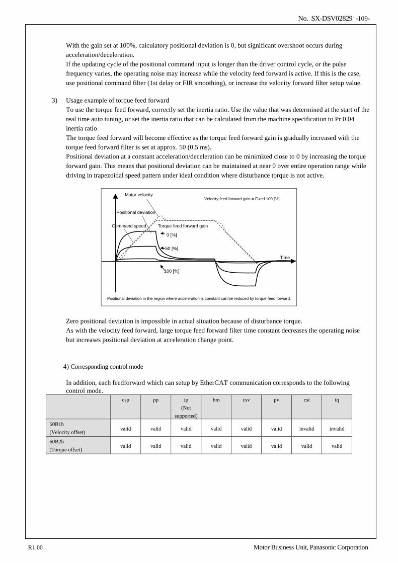
No. SX-DSV02829 -109-
With the gain set at 100%, calculatory positional deviation is 0, but significant overshoot occurs during acceleration/deceleration. If the updating cycle of the positional command input is longer than the driver control cycle, or the pulse frequency varies, the operating noise may increase while the velocity feed forward is active. If this is the case, use positional command filter (1st delay or FIR smoothing), or increase the velocity forward filter setup value.
3) Usage example of torque feed forward
To use the torque feed forward, correctly set the inertia ratio. Use the value that was determined at the start of the real time auto tuning, or set the inertia ratio that can be calculated from the machine specification to Pr 0.04 inertia ratio. The torque feed forward will become effective as the torque feed forward gain is gradually increased with the torque feed forward filter is set at approx. 50 (0.5 ms). Positional deviation at a constant acceleration/deceleration can be minimized close to 0 by increasing the torque forward gain. This means that positional deviation can be maintained at near 0 over entire operation range while driving in trapezoidal speed pattern under ideal condition where disturbance torque is not active.
Command speed
Motor velocity
Positional deviation
Positional deviation in the region where acceleration is constant can be reduced by torque feed forward.
Velocity feed forward gain = Fixed 100 [%]
100 [%]
0 [%]
Torque feed forward gain
50 [%]
Time
Zero positional deviation is impossible in actual situation because of disturbance torque. As with the velocity feed forward, large torque feed forward filter time constant decreases the operating noise but increases positional deviation at acceleration change point.
4) Corresponding control mode In addition, each feedforward which can setup by EtherCAT communication corresponds to the following control mode.
csp pp ip (Not
supported)
hm csv pv cst tq
60B1h (Velocity offset) valid valid valid valid valid valid invalid invalid
60B2h (Torque offset) valid valid valid valid valid valid valid valid
R1.00 Motor Business Unit, Panasonic Corporation
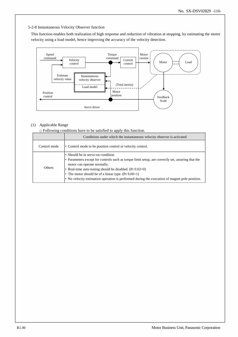
No. SX-DSV02829 -110-
5-2-8 Instantaneous Velocity Observer function
This function enables both realization of high response and reduction of vibration at stopping, by estimating the motor velocity using a load model, hence improving the accuracy of the velocity detection.
Current control
Velocity control
Speed command
Torque command
Instantaneous velocity observer
Load model
Motor current
Motor
Feedback Scale
Servo driver
Motor position
Position control
Load
(Total inertia)
Estimate velocity value
(1) Applicable Range Following conditions have to be satisfied to apply this function.
Conditions under which the instantaneous velocity observer is activated
Control mode • Control mode to be position control or velocity control.
Others
• Should be in servo-on condition • Parameters except for controls such as torque limit setup, are correctly set, assuring that the
motor can operate normally. • Real-time auto-tuning should be disabled. (Pr 0.02=0) • The motor should be of a linear type. (Pr 9.00=1) • No velocity estimation operation is performed during the execution of magnet pole position.
R1.00 Motor Business Unit, Panasonic Corporation
No. SX-DSV02829 -111-
(2) Cautions
This function does not work properly or no effect is obtained under the following conditions. Conditions which obstruct instantaneous velocity observer action
Load
• Gap between the estimated total load inertia (motor+load) and actual machine is large. e.g.) Large resonance point exists in frequency band of 300 [Hz] or below. Non-linear factor
such as large backlash exists. • Load inertia varies. • Disturbance torque with harmonic component is applied.
Others • Settling range is very small.
(3) Parameters
Class No. At- trib-
ute *1) Title Range Unit Function
6 10 B Function
expansion setup 0–1023 —
Velocity observer enable bit (bit 0) valid/invalid the function. bit 0 0: Invalid 1: Valid * bit 0 = LSB
*1) For parameter attribute, refer to Section 9-1.
(4) How to Use
(1) Setup of inertia ratio (Pr 0.04) Set up as exact inertia ratio as possible. • When the inertia ratio (Pr 0.04) is already obtained through real-time auto-gain tuning and is applicable at
normal position control, use this value as Pr 0.04 setup value. • When the inertia ratio is already known through calculation, enter this calculated value. • When the inertia ration is not known, execute the normal mode auto-gain tuning and measure the inertia ratio.
(2) Adjustment at normal position control
• Adjust the position loop gain, velocity loop gain, etc.
(3) Setup of instantaneous velocity observer (Pr 6.10) • By enabling instantaneous velocity observer function through function expansion setup (Pr 6.10), the velocity
detection method changes to the instantaneous velocity observer. • When you experience a large variation of the torque waveform or noise, return this to 0, and reconfirm the
above cautions and (1). • When you obtain the effect such as a reduction of the variation of the torque waveform and noise, search an
optimum setup by making a fine adjustment of Pr 0.04 (inertia ratio) while observing the position deviation waveform and actual velocity waveform to obtain the least variation. If you change the position loop gain and velocity loop gain, the optimum value of the inertia ratio (Pr 0.04) might have been changed, and you need to make a fine adjustment again.
R1.00 Motor Business Unit, Panasonic Corporation
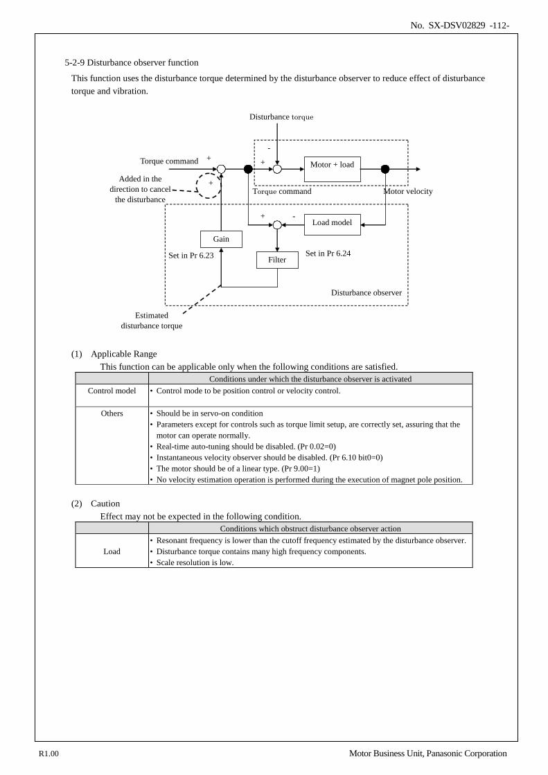
No. SX-DSV02829 -112-
5-2-9 Disturbance observer function
This function uses the disturbance torque determined by the disturbance observer to reduce effect of disturbance torque and vibration.
Motor + load +
-
Load model + -
Filter
Gain
+
+
Disturbance observer
Added in the direction to cancel
the disturbance
Set in Pr 6.23 Set in Pr 6.24
Estimated disturbance torque
Disturbance torque
Motor velocity Torque command
Torque command
(1) Applicable Range This function can be applicable only when the following conditions are satisfied.
Conditions under which the disturbance observer is activated Control model • Control mode to be position control or velocity control.
Others • Should be in servo-on condition
• Parameters except for controls such as torque limit setup, are correctly set, assuring that the motor can operate normally.
• Real-time auto-tuning should be disabled. (Pr 0.02=0) • Instantaneous velocity observer should be disabled. (Pr 6.10 bit0=0) • The motor should be of a linear type. (Pr 9.00=1) • No velocity estimation operation is performed during the execution of magnet pole position.
(2) Caution
Effect may not be expected in the following condition. Conditions which obstruct disturbance observer action
Load • Resonant frequency is lower than the cutoff frequency estimated by the disturbance observer. • Disturbance torque contains many high frequency components. • Scale resolution is low.
R1.00 Motor Business Unit, Panasonic Corporation
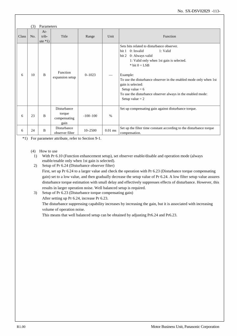
No. SX-DSV02829 -113-
(3) Parameters
Class No. At- trib-
ute *1) Title Range Unit Function
6 10 B Function
expansion setup 0–1023 —
Sets bits related to disturbance observer. bit 1 0: Invalid 1: Valid bit 2 0: Always valid 1: Valid only when 1st gain is selected. * bit 0 = LSB Example: To use the disturbance observer in the enabled mode only when 1st gain is selected: Setup value = 6 To use the disturbance observer always in the enabled mode: Setup value = 2
6 23 B
Disturbance torque
compensating gain
-100–100 %
Set up compensating gain against disturbance torque.
6 24 B Disturbance
observer filter 10–2500 0.01 ms
Set up the filter time constant according to the disturbance torque compensation.
*1) For parameter attribute, refer to Section 9-1.
(4) How to use
1) With Pr 6.10 (Function enhancement setup), set observer enable/disable and operation mode (always enable/enable only when 1st gain is selected).
2) Setup of Pr 6.24 (Disturbance observer filter) First, set up Pr 6.24 to a larger value and check the operation with Pr 6.23 (Disturbance torque compensating gain) set to a low value, and then gradually decrease the setup value of Pr 6.24. A low filter setup value assures disturbance torque estimation with small delay and effectively suppresses effects of disturbance. However, this results in larger operation noise. Well balanced setup is required.
3) Setup of Pr 6.23 (Disturbance torque compensating gain) After setting up Pr 6.24, increase Pr 6.23. The disturbance suppressing capability increases by increasing the gain, but it is associated with increasing volume of operation noise. This means that well balanced setup can be obtained by adjusting Pr6.24 and Pr6.23.
R1.00 Motor Business Unit, Panasonic Corporation
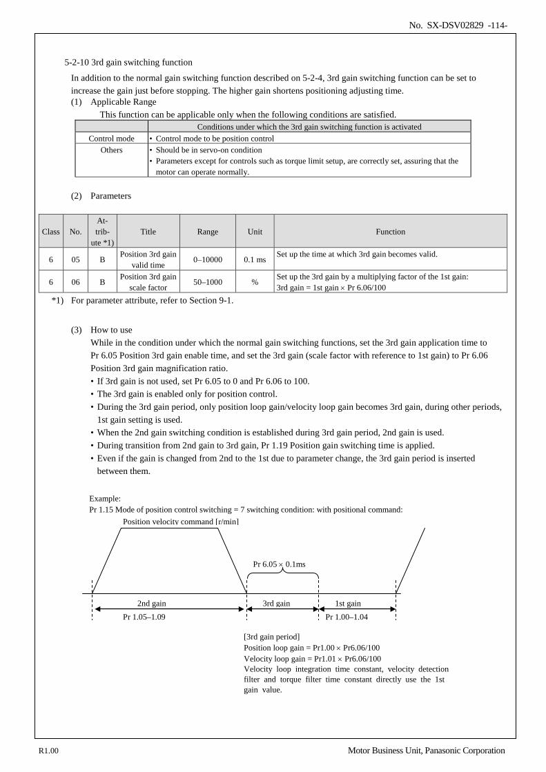
No. SX-DSV02829 -114-
5-2-10 3rd gain switching function
In addition to the normal gain switching function described on 5-2-4, 3rd gain switching function can be set to increase the gain just before stopping. The higher gain shortens positioning adjusting time. (1) Applicable Range
This function can be applicable only when the following conditions are satisfied. Conditions under which the 3rd gain switching function is activated
Control mode • Control mode to be position control Others • Should be in servo-on condition
• Parameters except for controls such as torque limit setup, are correctly set, assuring that the motor can operate normally.
(2) Parameters
Class No. At- trib-
ute *1) Title Range Unit Function
6 05 B Position 3rd gain
valid time 0–10000 0.1 ms
Set up the time at which 3rd gain becomes valid.
6 06 B Position 3rd gain
scale factor 50–1000 %
Set up the 3rd gain by a multiplying factor of the 1st gain: 3rd gain = 1st gain × Pr 6.06/100
*1) For parameter attribute, refer to Section 9-1.
(3) How to use
While in the condition under which the normal gain switching functions, set the 3rd gain application time to Pr 6.05 Position 3rd gain enable time, and set the 3rd gain (scale factor with reference to 1st gain) to Pr 6.06 Position 3rd gain magnification ratio. • If 3rd gain is not used, set Pr 6.05 to 0 and Pr 6.06 to 100. • The 3rd gain is enabled only for position control. • During the 3rd gain period, only position loop gain/velocity loop gain becomes 3rd gain, during other periods,
1st gain setting is used. • When the 2nd gain switching condition is established during 3rd gain period, 2nd gain is used. • During transition from 2nd gain to 3rd gain, Pr 1.19 Position gain switching time is applied. • Even if the gain is changed from 2nd to the 1st due to parameter change, the 3rd gain period is inserted
between them.
2nd gain
Example: Pr 1.15 Mode of position control switching = 7 switching condition: with positional command:
3rd gain 1st gain
Position velocity command [r/min]
Pr 6.05 × 0.1ms
Pr 1.05–1.09
[3rd gain period] Position loop gain = Pr1.00 × Pr6.06/100 Velocity loop gain = Pr1.01 × Pr6.06/100 Velocity loop integration time constant, velocity detection filter and torque filter time constant directly use the 1st gain value.
Pr 1.00–1.04
R1.00 Motor Business Unit, Panasonic Corporation
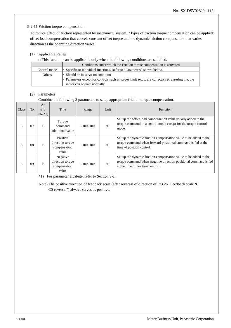
No. SX-DSV02829 -115-
5-2-11 Friction torque compensation
To reduce effect of friction represented by mechanical system, 2 types of friction torque compensation can be applied: offset load compensation that cancels constant offset torque and the dynamic friction compensation that varies direction as the operating direction varies.
(1) Applicable Range
This function can be applicable only when the following conditions are satisfied. Conditions under which the Friction torque compensation is activated
Control mode • Specific to individual functions. Refer to “Parameters” shown below. Others • Should be in servo-on condition
• Parameters except for controls such as torque limit setup, are correctly set, assuring that the motor can operate normally.
(2) Parameters
Combine the following 3 parameters to setup appropriate friction torque compensation.
Class No. At- trib-
ute *1) Title Range Unit Function
6 07 B Torque
command additional value
-100–100 %
Set up the offset load compensation value usually added to the torque command in a control mode except for the torque control mode.
6 08 B
Positive direction torque compensation
value
-100–100 %
Set up the dynamic friction compensation value to be added to the torque command when forward positional command is fed at the time of position control.
6 09 B
Negative direction torque compensation
value
-100–100 %
Set up the dynamic friction compensation value to be added to the torque command when negative direction positional command is fed at the time of position control.
*1) For parameter attribute, refer to Section 9-1.
Note) The positive direction of feedback scale (after reversal of direction of Pr3.26 "Feedback scale & CS reversal") always serves as positive.
R1.00 Motor Business Unit, Panasonic Corporation
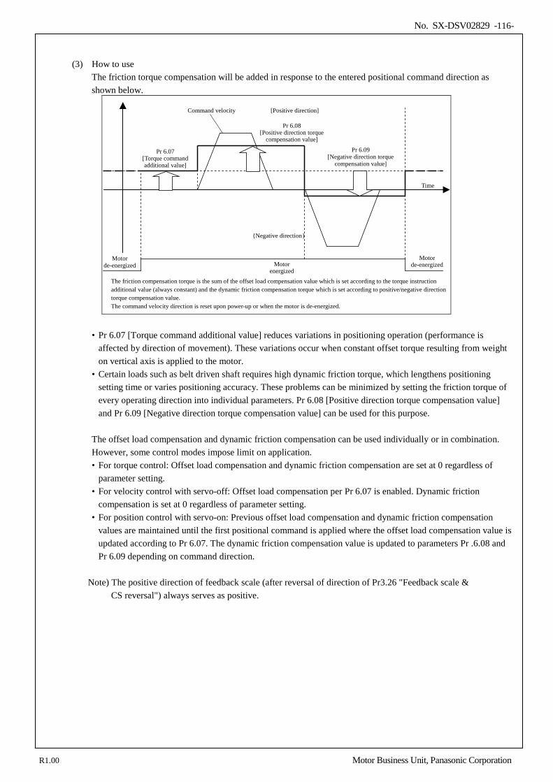
No. SX-DSV02829 -116-
(3) How to use
The friction torque compensation will be added in response to the entered positional command direction as shown below.
Command velocity
The friction compensation torque is the sum of the offset load compensation value which is set according to the torque instruction additional value (always constant) and the dynamic friction compensation torque which is set according to positive/negative direction torque compensation value. The command velocity direction is reset upon power-up or when the motor is de-energized.
Time
Motor de-energized
Motor
energized
Motor de-energized
Pr 6.07 [Torque command additional value]
[Positive direction]
Negative direction
Pr 6.08 [Positive direction torque
compensation value]
Pr 6.09 [Negative direction torque
compensation value]
• Pr 6.07 [Torque command additional value] reduces variations in positioning operation (performance is affected by direction of movement). These variations occur when constant offset torque resulting from weight on vertical axis is applied to the motor.
• Certain loads such as belt driven shaft requires high dynamic friction torque, which lengthens positioning setting time or varies positioning accuracy. These problems can be minimized by setting the friction torque of every operating direction into individual parameters. Pr 6.08 [Positive direction torque compensation value] and Pr 6.09 [Negative direction torque compensation value] can be used for this purpose.
The offset load compensation and dynamic friction compensation can be used individually or in combination. However, some control modes impose limit on application. • For torque control: Offset load compensation and dynamic friction compensation are set at 0 regardless of
parameter setting. • For velocity control with servo-off: Offset load compensation per Pr 6.07 is enabled. Dynamic friction
compensation is set at 0 regardless of parameter setting. • For position control with servo-on: Previous offset load compensation and dynamic friction compensation
values are maintained until the first positional command is applied where the offset load compensation value is updated according to Pr 6.07. The dynamic friction compensation value is updated to parameters Pr .6.08 and Pr 6.09 depending on command direction.
Note) The positive direction of feedback scale (after reversal of direction of Pr3.26 "Feedback scale &
CS reversal") always serves as positive.
R1.00 Motor Business Unit, Panasonic Corporation
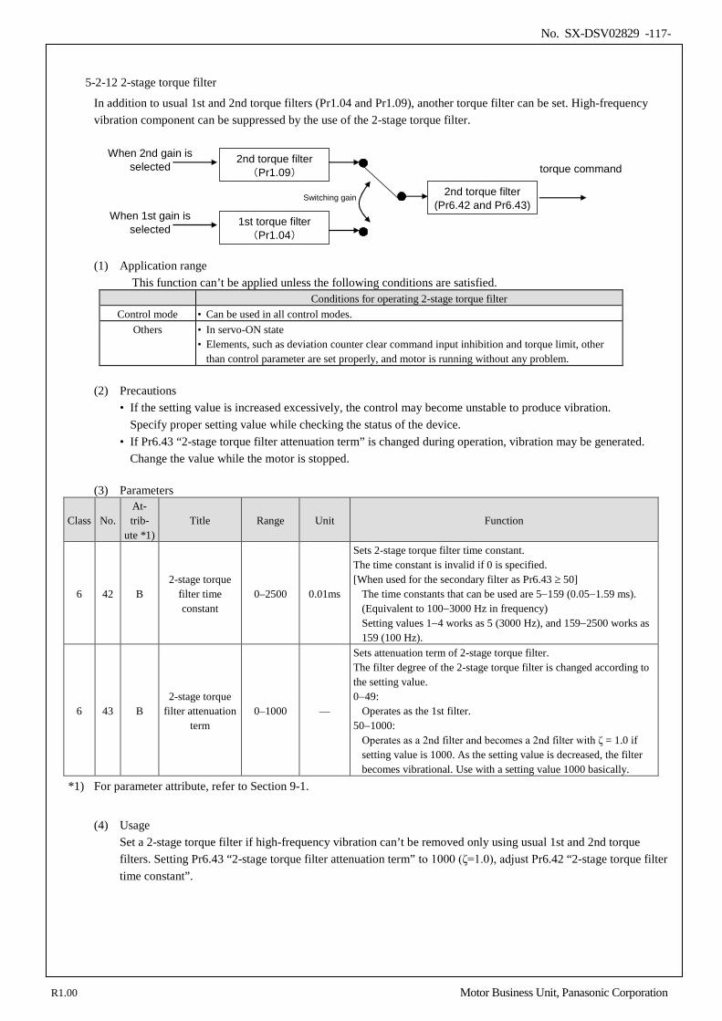
No. SX-DSV02829 -117-
5-2-12 2-stage torque filter
In addition to usual 1st and 2nd torque filters (Pr1.04 and Pr1.09), another torque filter can be set. High-frequency vibration component can be suppressed by the use of the 2-stage torque filter.
2nd torque filter (Pr1.09)
When 2nd gain is selected torque command
1st torque filter (Pr1.04)
When 1st gain is selected
2nd torque filter (Pr6.42 and Pr6.43)
Switching gain
(1) Application range
This function can’t be applied unless the following conditions are satisfied. Conditions for operating 2-stage torque filter
Control mode • Can be used in all control modes. Others • In servo-ON state
• Elements, such as deviation counter clear command input inhibition and torque limit, other than control parameter are set properly, and motor is running without any problem.
(2) Precautions
• If the setting value is increased excessively, the control may become unstable to produce vibration. Specify proper setting value while checking the status of the device.
• If Pr6.43 “2-stage torque filter attenuation term” is changed during operation, vibration may be generated. Change the value while the motor is stopped.
(3) Parameters
Class No. At- trib-
ute *1) Title Range Unit Function
6 42 B 2-stage torque
filter time constant
0–2500 0.01ms
Sets 2-stage torque filter time constant. The time constant is invalid if 0 is specified. [When used for the secondary filter as Pr6.43 ≥ 50]
The time constants that can be used are 5−159 (0.05−1.59 ms). (Equivalent to 100−3000 Hz in frequency) Setting values 1−4 works as 5 (3000 Hz), and 159−2500 works as 159 (100 Hz).
6 43 B 2-stage torque
filter attenuation term
0–1000 —
Sets attenuation term of 2-stage torque filter. The filter degree of the 2-stage torque filter is changed according to the setting value. 0−49:
Operates as the 1st filter. 50−1000:
Operates as a 2nd filter and becomes a 2nd filter with ζ = 1.0 if setting value is 1000. As the setting value is decreased, the filter becomes vibrational. Use with a setting value 1000 basically.
*1) For parameter attribute, refer to Section 9-1.
(4) Usage
Set a 2-stage torque filter if high-frequency vibration can’t be removed only using usual 1st and 2nd torque filters. Setting Pr6.43 “2-stage torque filter attenuation term” to 1000 (ζ=1.0), adjust Pr6.42 “2-stage torque filter time constant”.
R1.00 Motor Business Unit, Panasonic Corporation
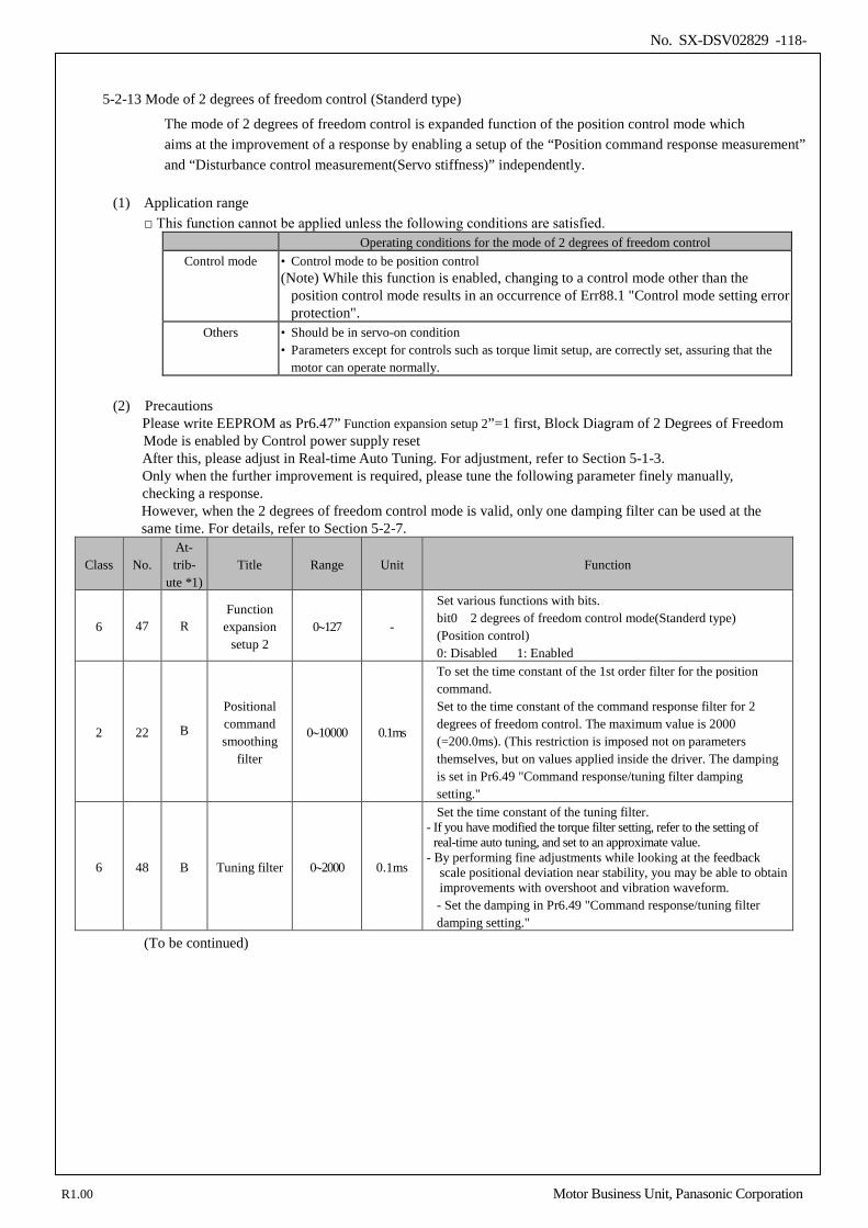
No. SX-DSV02829 -118-
5-2-13 Mode of 2 degrees of freedom control (Standerd type)
The mode of 2 degrees of freedom control is expanded function of the position control mode which aims at the improvement of a response by enabling a setup of the “Position command response measurement” and “Disturbance control measurement(Servo stiffness)” independently.
(1) Application range This function cannot be applied unless the following conditions are satisfied.
Operating conditions for the mode of 2 degrees of freedom control Control mode • Control mode to be position control
(Note) While this function is enabled, changing to a control mode other than the position control mode results in an occurrence of Err88.1 "Control mode setting error protection".
Others • Should be in servo-on condition • Parameters except for controls such as torque limit setup, are correctly set, assuring that the
motor can operate normally.
(2) Precautions Please write EEPROM as Pr6.47” Function expansion setup 2”=1 first, Block Diagram of 2 Degrees of Freedom
Mode is enabled by Control power supply reset After this, please adjust in Real-time Auto Tuning. For adjustment, refer to Section 5-1-3. Only when the further improvement is required, please tune the following parameter finely manually, checking a response. However, when the 2 degrees of freedom control mode is valid, only one damping filter can be used at the same time. For details, refer to Section 5-2-7.
Class No. At- trib-
ute *1) Title Range Unit Function
6 47 R Function
expansion setup 2
0∼127 -
Set various functions with bits. bit0 2 degrees of freedom control mode(Standerd type) (Position control) 0: Disabled 1: Enabled
2 22 B
Positional command smoothing
filter
0∼10000 0.1ms
To set the time constant of the 1st order filter for the position command. Set to the time constant of the command response filter for 2 degrees of freedom control. The maximum value is 2000 (=200.0ms). (This restriction is imposed not on parameters themselves, but on values applied inside the driver. The damping is set in Pr6.49 "Command response/tuning filter damping setting."
6 48 B Tuning filter 0∼2000 0.1ms
Set the time constant of the tuning filter. - If you have modified the torque filter setting, refer to the setting of
real-time auto tuning, and set to an approximate value. - By performing fine adjustments while looking at the feedback
scale positional deviation near stability, you may be able to obtain improvements with overshoot and vibration waveform. - Set the damping in Pr6.49 "Command response/tuning filter damping setting."
(To be continued)
R1.00 Motor Business Unit, Panasonic Corporation
No. SX-DSV02829 -119-
Class No. At- trib-
ute *1) Title Range Unit Function
6 49 B Command / tuning filter
damping 0∼99 -
Set the damping of the command filter and tuning filter. The first digit is set for the command filter and the second digit is for the tuning filter in decimal notation. Effective digits 0 to 4: No damping (Operates as a primary filter) 5 to 9: Secondary filter (The damping ζ will be 1.0, 0.86, 0.71, 0.50 and 0.35 respectively.) Ex) To obtain ζ=1.0 for the command filter and ζ=0.71 for the tuning filter 1, set the value to 75 (1st digit=5 (ζ=1.0), 2nd digit=7(ζ=0.71)). Please note that for the time constant of the command filter, Pr2.22 "Positional command smoothing filter" will be applied.
6 50 B
Viscous friction
compensating gain
0∼10000 0.1%/ (10000 r/min)
The command speed is multiplied by this set value to obtain a compensation amount that will be added to the torque command. - By setting the estimated value of viscous friction coefficient for real-time auto tuning, you may be able to obtain improvements with the feedback scale positional deviation at near stability.
6 71 B
2nd Viscous friction
compensating gain
0~10000 0.1%/ (10000 r/min)
Sets the 2nd viscous friction compensating gain The unit is [rated torque 0.1%/ (10000 r/min)].
*1) For the parameter attributes, refer to Section 9-1.
R1.00 Motor Business Unit, Panasonic Corporation
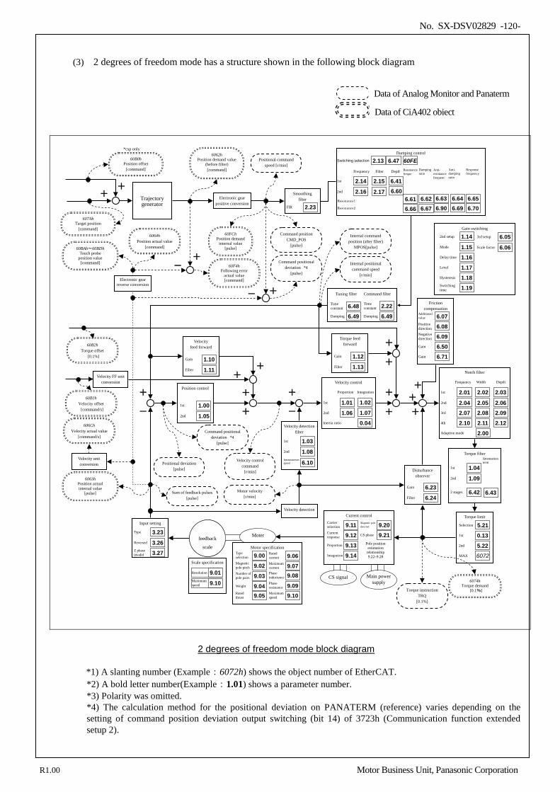
No. SX-DSV02829 -120-
(3) 2 degrees of freedom mode has a structure shown in the following block diagram
Velocity feed forward
Gain 1.10 Filter 1.11
Smoothing filter
FIR 2.23
+
-
Position control
1st 1.00 2nd 1.05
+
+
+
-
Velocity detection
Friction compensation
Additional value 6.07 Positive direction 6.08 Negative direction 6.09
Disturbance observer
Gain 6.23 Filter 6.24
Gain switching
2nd setup 1.14 Mode 1.15 Delay time 1.16 Level 1.17 Hysteresis 1.18 Switching time 1.19
3rd setup 6.05 Scale factor 6.06
Torque limit
Selection 5.21
Torque feed forward
Gain 1.12 Filter 1.13
6074h Torque demand
[0.1%]
60F4h Following error
actual value [command]
+ +
+ +
+
6063h Position actual internal value
[pulse]
Velocity detection filter
1st 1.03 2nd 1.08 Instantaneous speed 6.10
Notch filter
2.03
2.06 2.09 2.12
Depth
2.02
2.05 2.08 2.11
Width
1st 2.01 2nd 2.04 3rd 2.07 4th 2.10
Frequency
Adaptive mode 2.00
Velocity control
1.02
1.07
Proportion Integration
Inertia ratio
1st 1.01 2nd 1.06
0.04
6064h Position actual value
[command] 60BAh~60BDh Touch probe
position value [command]
Trajectory generator
606Ch Velocity actual value
[command/s]
60B1h Velocity offset [command/s]
+ + Velocity FF unit
conversion
60FCh Position demand
internal value [pulse]
60B2h Torque offset
[0.1%]
+
+
MAX 6072
1st 0.13 2nd 5.22
Electronic gear positive conversion
6062h Position demand value
(before filter) [command]
- +
607Ah Target position
[command]
Electronic gear reverse conversion
Positional command speed [r/min]
Command position CMD_POS
[pulse]
Positional deviation [pulse]
Velocity control command
[r/min]
Motor velocity [r/min]
Internal positional command speed
[r/min]
Internal command position (after filter)
MPOS[pulse]
+ +
60B0h Position offset
[command]
*csp only
Command positional deviation *4
[pulse]
Command positional deviation *4
[pulse]
Sum of feedback pulses [pulse]
Torque instruction TRQ
[0.1%]
- +
Damping control
1st 2.14 2nd 2.16
2.15 2.17
Switching selection 2.13 Frequency Filter Depth
6.41
Tuning filter Command filter
Time constant 6.48
Damping 6.49
Time constant 2.22
Damping 6.49
Torque filter
1st
1.04
2nd
1.09
2 stages 6.42
Attenuation term
6.43
Gain 6.50 Gain 6.71
6.47
60FE
6.60 Resonance1
Resonance2
6.62
6.61
6.63
6.64 6.67
6.66
6.90
6.69
6.65 6.70
Main power supply
Current control
Current response 9.12 Proportion 9.13
Carrier selection 9.11
Integration 9.14
Magnetic pole detected 9.20 CS phase 9.21
Pole position estimation
relationship 9.22–9.28
CS signal
エンコーダ
feedback
scale
Input setting
Type 3.23 Reversed 3.26 Z phase invalid 3.27
Scale specification
Resolution 9.01 Maximum speed 9.10
Moter
Motor specification
Magnetic pole pitch 9.02 Number of pole pairs 9.03
Type selection 9.00
Weight 9.04 Rated thrust 9.05
Rated current 9.06 Maximum current 9.07
Maximum speed 9.10
Phase inductance 9.08 Phase resistance 9.09
Resonance freque
Damping ratio
Anti- resonance frequenc
Anti- damping ratio
Response frequency
Velocity unit conversion
2 degrees of freedom mode block diagram
*1) A slanting number (Example:6072h) shows the object number of EtherCAT. *2) A bold letter number(Example:1.01) shows a parameter number. *3) Polarity was omitted. *4) The calculation method for the positional deviation on PANATERM (reference) varies depending on the setting of command position deviation output switching (bit 14) of 3723h (Communication function extended setup 2).
Data of CiA402 object
Data of Analog Monitor and Panaterm
R1.00 Motor Business Unit, Panasonic Corporation
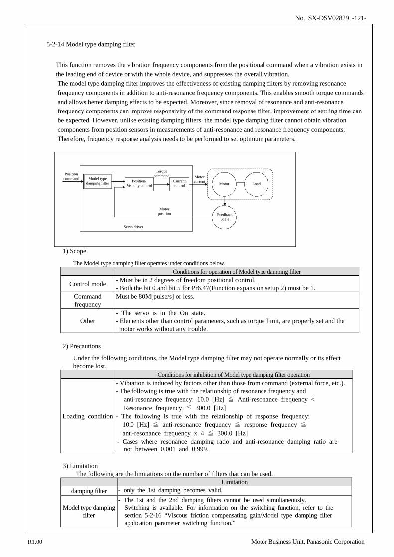
No. SX-DSV02829 -121-
5-2-14 Model type damping filter
This function removes the vibration frequency components from the positional command when a vibration exists in the leading end of device or with the whole device, and suppresses the overall vibration. The model type damping filter improves the effectiveness of existing damping filters by removing resonance frequency components in addition to anti-resonance frequency components. This enables smooth torque commands and allows better damping effects to be expected. Moreover, since removal of resonance and anti-resonance frequency components can improve responsivity of the command response filter, improvement of settling time can be expected. However, unlike existing damping filters, the model type damping filter cannot obtain vibration components from position sensors in measurements of anti-resonance and resonance frequency components. Therefore, frequency response analysis needs to be performed to set optimum parameters.
Current control
Position/ Velocity control
Position command
Torque command Motor
current Motor
Feedback Scale
Servo driver
Motor position
Load Model type
damping filter
1) Scope
The Model type damping filter operates under conditions below. Conditions for operation of Model type damping filter
Control mode - Must be in 2 degrees of freedom positional control. - Both the bit 0 and bit 5 for Pr6.47(Function expansion setup 2) must be 1.
Command frequency
Must be 80M[pulse/s] or less.
Other - The servo is in the On state. - Elements other than control parameters, such as torque limit, are properly set and the
motor works without any trouble.
2) Precautions
Under the following conditions, the Model type damping filter may not operate normally or its effect become lost.
Conditions for inhibition of Model type damping filter operation
Loading condition
- Vibration is induced by factors other than those from command (external force, etc.). - The following is true with the relationship of resonance frequency and
anti-resonance frequency: 10.0 [Hz] ≦ Anti-resonance frequency < Resonance frequency ≦ 300.0 [Hz]
- The following is true with the relationship of response frequency: 10.0 [Hz] ≦ anti-resonance frequency ≦ response frequency ≦
anti-resonance frequency x 4 ≦ 300.0 [Hz] - Cases where resonance damping ratio and anti-resonance damping ratio are not between 0.001 and 0.999.
3) Limitation The following are the limitations on the number of filters that can be used. Limitation
damping filter - only the 1st damping becomes valid.
Model type damping filter
- The 1st and the 2nd damping filters cannot be used simultaneously. Switching is available. For information on the switching function, refer to the section 5-2-16 “Viscous friction compensating gain/Model type damping filter application parameter switching function.”
R1.00 Motor Business Unit, Panasonic Corporation
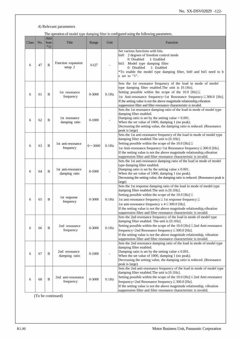
No. SX-DSV02829 -122-
4) Relevant parameters
The operation of model type damping filter is configured using the following parameters.
Class No. Attribute *1)
Title Range Unit Function
6 47 R Function expansion setup 2 0-127 -
Set various functions with bits. bit0 2 degrees of freedom control mode
0: Disabled 1: Enabled bit5 Model type damping filter
0: Disabled 1: Enabled *To enable the model type damping filter, bit0 and bit5 need to be set to “1”.
6 61 B 1st resonance frequency 0-3000 0.1Hz
Sets the 1st resonance frequency of the load in mode of model type damping filter enabled.The unit is [0.1Hz]. Setting possible within the scope of the 10.0 [Hz]≦ 1st Anti-resonance frequency<1st Resonance frequency≦300.0 [Hz]. If the setting value is not the above magnitude relationship,vibration suppression filter and filter resonance characteristic is invalid.
6 62 B 1st resonance damping ratio 0-1000 -
Sets the 1st resonance damping ratio of the load in mode of model type damping filter enabled. Damping ratio is set by the setting value × 0.001. When the set value of 1000, damping 1 (no peak). Decreasing the setting value, the damping ratio is reduced. (Resonance peak is large)
6 63 B 1st anti-resonance frequency 0~3000 0.1Hz
Sets the 1st anti-resonance frequency of the load in mode of model type damping filter enabled.The unit is [0.1Hz]. Setting possible within the scope of the 10.0 [Hz]≦ 1st Anti-resonance frequency<1st Resonance frequency≦300.0 [Hz]. If the setting value is not the above magnitude relationship,vibration suppression filter and filter resonance characteristic is invalid.
6 64 B 1st anti-resonance damping ratio 0-1000 -
Sets the 1st anti-resonance damping ratio of the load in mode of model type damping filter enabled. Damping ratio is set by the setting value x 0.001. When the set value of 1000, damping 1 (no peak). Decreasing the setting value, the damping ratio is reduced. (Resonance peak is large)
6 65 B 1st response frequency 0-3000 0.1Hz
Sets the 1st response damping ratio of the load in mode of model type damping filter enabled.The unit is [0.1Hz]. Setting possible within the scope of the 10.0 [Hz]≦ 1st anti-resonance frequency≦1st response frequency≦ 1st anti-resonance frequency x 4≦300.0 [Hz]. If the setting value is not the above magnitude relationship,vibration suppression filter and filter resonance characteristic is invalid.
6 66 B 2nd resonance frequency 0-3000 0.1Hz
Sets the 2nd resonance frequency of the load in mode of model type damping filter enabled. The unit is [0.1Hz]. Setting possible within the scope of the 10.0 [Hz]≦2nd Anti-resonance frequency<2nd Resonance frequency≦300.0 [Hz]. If the setting value is not the above magnitude relationship, vibration suppression filter and filter resonance characteristic is invalid.
6 67 B 2nd resonance damping ratio 0-1000 -
Sets the 2nd resonance damping ratio of the load in mode of model type damping filter enabled. Damping ratio is set by the setting value x 0.001. When the set value of 1000, damping 1 (no peak). Decreasing the setting value, the damping ratio is reduced. (Resonance peak is large)
6 68 B 2nd anti-resonance frequency 0-3000 0.1Hz
Sets the 2nd anti-resonance frequency of the load in mode of model type damping filter enabled.The unit is [0.1Hz]. Setting possible within the scope of the 10.0 [Hz]≦2nd Anti-resonance frequency<2nd Resonance frequency≦300.0 [Hz]. If the setting value is not the above magnitude relationship, vibration suppression filter and filter resonance characteristic is invalid.
(To be continued)
R1.00 Motor Business Unit, Panasonic Corporation
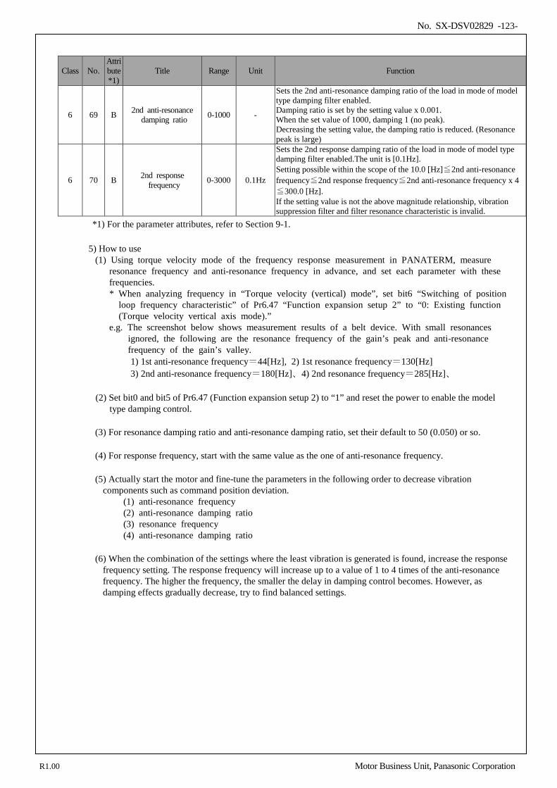
No. SX-DSV02829 -123-
Class No. Attribute *1)
Title Range Unit Function
6 69 B 2nd anti-resonance damping ratio 0-1000 -
Sets the 2nd anti-resonance damping ratio of the load in mode of model type damping filter enabled. Damping ratio is set by the setting value x 0.001. When the set value of 1000, damping 1 (no peak). Decreasing the setting value, the damping ratio is reduced. (Resonance peak is large)
6 70 B 2nd response frequency 0-3000 0.1Hz
Sets the 2nd response damping ratio of the load in mode of model type damping filter enabled.The unit is [0.1Hz]. Setting possible within the scope of the 10.0 [Hz]≦2nd anti-resonance frequency≦2nd response frequency≦2nd anti-resonance frequency x 4≦300.0 [Hz]. If the setting value is not the above magnitude relationship, vibration suppression filter and filter resonance characteristic is invalid.
*1) For the parameter attributes, refer to Section 9-1.
5) How to use (1) Using torque velocity mode of the frequency response measurement in PANATERM, measure
resonance frequency and anti-resonance frequency in advance, and set each parameter with these frequencies.
* When analyzing frequency in “Torque velocity (vertical) mode”, set bit6 “Switching of position loop frequency characteristic” of Pr6.47 “Function expansion setup 2” to “0: Existing function (Torque velocity vertical axis mode).”
e.g. The screenshot below shows measurement results of a belt device. With small resonances ignored, the following are the resonance frequency of the gain’s peak and anti-resonance frequency of the gain’s valley.
1) 1st anti-resonance frequency=44[Hz], 2) 1st resonance frequency=130[Hz] 3) 2nd anti-resonance frequency=180[Hz]、4) 2nd resonance frequency=285[Hz]、
(2) Set bit0 and bit5 of Pr6.47 (Function expansion setup 2) to “1” and reset the power to enable the model type damping control.
(3) For resonance damping ratio and anti-resonance damping ratio, set their default to 50 (0.050) or so.
(4) For response frequency, start with the same value as the one of anti-resonance frequency.
(5) Actually start the motor and fine-tune the parameters in the following order to decrease vibration components such as command position deviation.
(1) anti-resonance frequency (2) anti-resonance damping ratio (3) resonance frequency (4) anti-resonance damping ratio
(6) When the combination of the settings where the least vibration is generated is found, increase the response frequency setting. The response frequency will increase up to a value of 1 to 4 times of the anti-resonance frequency. The higher the frequency, the smaller the delay in damping control becomes. However, as damping effects gradually decrease, try to find balanced settings.
R1.00 Motor Business Unit, Panasonic Corporation
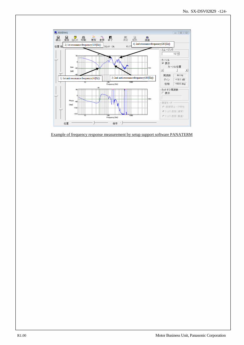
No. SX-DSV02829 -124-
Example of frequency response measurement by setup support software PANATERM
R1.00 Motor Business Unit, Panasonic Corporation
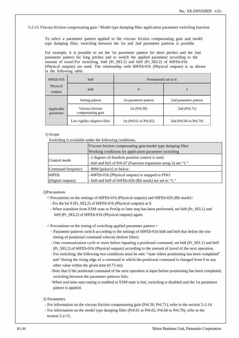
No. SX-DSV02829 -125-
5-2-15 Viscous friction compensating gain / Model type damping filter application parameter switching function
To select a parameter pattern applied to the viscous friction compensating gain and model type damping filter, switching between the 1st and 2nd parameter patterns is possible. For example, it is possible to set the 1st parameter pattern for short pitches and the 2nd parameter pattern for long pitches and to switch the applied parameter according to the amount of travel.For switching, bit8 (Pr_SEL1) and bit9 (Pr_SEL2) of 60FEh-01h (Physical outputs) are used. The relationship with 60FEh-01h (Physical outputs) is as shown in the following table.
60FEh-01h
Physical outputs
bit9 Permanently set at 0.
bit8 0 1
Applicable parameter
Setting pattern 1st parameter pattern 2nd parameter pattern
Viscous friction compensating gain
1st (Pr6.50) 2nd (Pr6.71)
Low rigidity adaptive filter 1st (Pr6.61 to Pr6.65) 2nd (Pr6.66 to Pr6.70)
1) Scope
Switching is available under the following conditions. Viscous friction compensating gain/model type damping filter
Working conditions for application parameter switching
Control mode - 2 degrees of freedom position control is used. - bit0 and bit5 of Pr6.47 (Function expansion setup 2) are “1.”
Command frequency - 80M [pulse/s] or below. 60FEh (Digital outputs)
- 60FEh-01h (Physical outputs) is mapped to PDO. - bit8 and bit9 of 60FEh-02h (Bit mask) are set to “1.”
2)Precautions < Precautions on the settings of 60FEh-01h (Physical outputs) and 60FEh-02h (Bit mask)>
- Fix the bit 9 (Pr_SEL2) of 60FEh-01h (Physical outputs) at 0. - When transition from ESM state to PreOp or later step has been performed, set bit8 (Pr_SEL1) and bit9 (Pr_SEL2) of 60FEh-01h (Physical outputs) again.
< Precautions on the timing of switching applied parameter pattern >
- Parameter patterns switch according to the settings of 60FEh-01h bit8 and bit9 that define the rise timing of positional command velocity (before filter).
- One communication cycle or more before inputting a positional command, set bit8 (Pr_SEL1) and bit9 (Pr_SEL2) of 60FEh-01h (Physical outputs) according to the amount of travel of the next operation.
- For switching, the following two conditions must be met: “state where positioning has been completed” and “during the rising edge of a command in which the positional command is changed from 0 to any other value within the given time (0.75 ms).
-Note that if the positional command of the next operation is input before positioning has been completed, switching between the parameter patterns fails.
-When real-time auto tuning is enabled or ESM state is Init, switching is disabled and the 1st parameter pattern is applied.
3) Parameters - For information on the viscous friction compensating gain (Pr6.50, Pr6.71), refer to the section 5-2-14. - For information on the model type damping filter (Pr6.61 to Pr6.65, Pr6.66 to Pr6.70), refer to the
section 5-2-15.
R1.00 Motor Business Unit, Panasonic Corporation
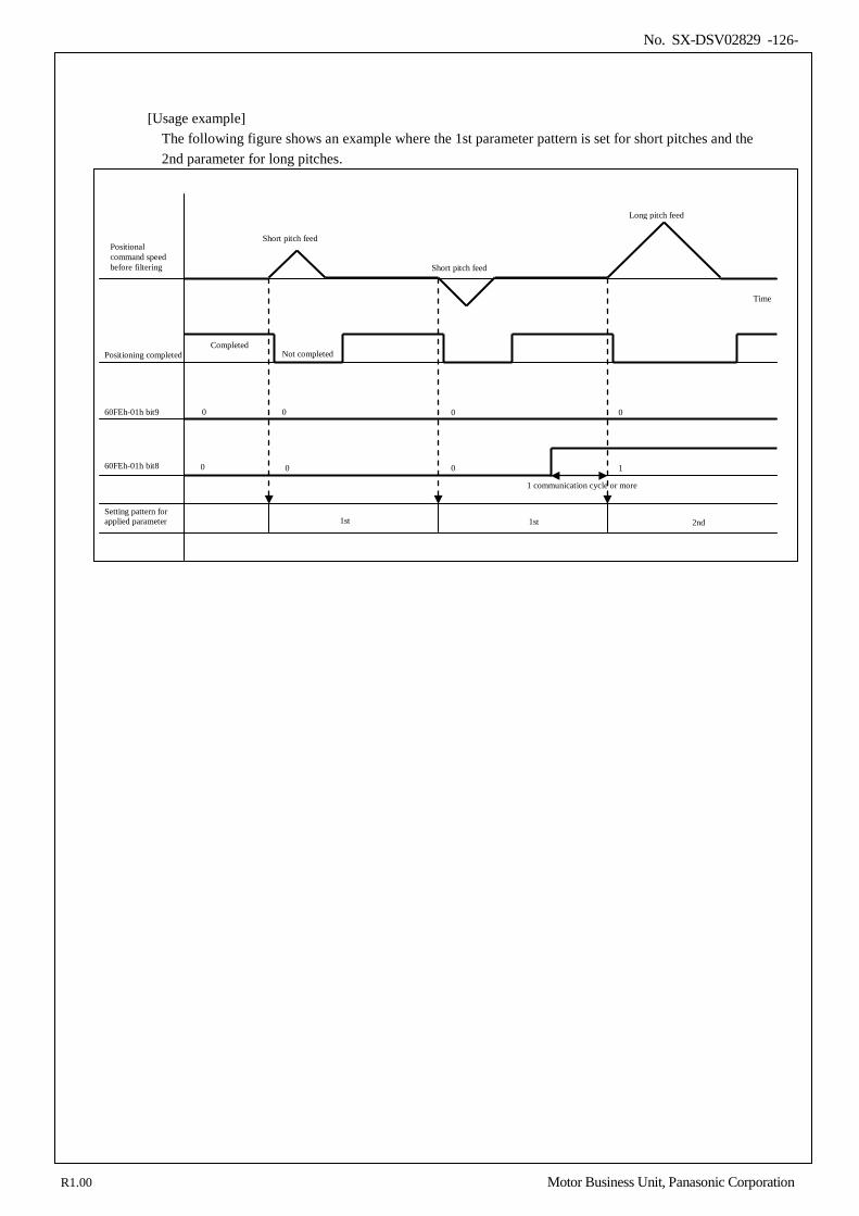
No. SX-DSV02829 -126-
[Usage example]
The following figure shows an example where the 1st parameter pattern is set for short pitches and the 2nd parameter for long pitches.
Positional command speed before filtering
Time
Short pitch feed Long pitch feed
Positioning completed
Short pitch feed
Completed Not completed
60FEh-01h bit9
60FEh-01h bit8
0
0 1
1st
1st
2nd
Setting pattern for applied parameter
1 communication cycle or more
0 0 0
0 0
R1.00 Motor Business Unit, Panasonic Corporation
No. SX-DSV02829 -127-
6.Application
6-1 Torque limit switching function ........................................................................................................................ 128 6-2 Motor working range setup function ................................................................................................................. 129 6-3 Deceleration stop sequence ............................................................................................................................... 131 6-3-1 Sequence upon inputting of over-travel inhibition (POT, NOT) (under review) ......................................... 131 6-3-2 Sequence at Servo-Off ................................................................................................................................. 133 6-3-3 Sequence at main power OFF ...................................................................................................................... 134 6-3-4 Sequence at alarm ........................................................................................................................................ 136 6-3-5 Emergency stop upon occurrence of alarm .................................................................................................. 138
6-4 Torque saturation protection function ............................................................................................................... 140
6
R1.00 Motor Business Unit, Panasonic Corporation
No. SX-DSV02829 -128-
6-1 Torque limit switching function
It is a function which changes a torque limit value by the direction of operation.
(1) Applicable range This function can be applicable only when the following conditions are satisfied.
Conditions under which the torque limit switching function is activated Control mode • Position control, velocity control. *1)
Others • Should be in servo-on condition • Parameters except for controls are correctly set, assuring that the motor can operate normally.
*1) During torque controlling, the switching function is disabled and only Pr. 0.13 1st torque limit is enabled.
(2) Parameters
Class No. At- trib-
ute *1) Title Range Unit Function
0 13 B 1st torque limit 0–500 % You can set up the 1st limit value of the motor output torque. *2)
5 21 B Selection of torque limit
1–4 —
You can set up the torque limiting method. Setup value
Negative direction
Positive direction
1 Pr0.13 2 Pr5.22 Pr0.13 3 Pr0.13 4 Pr5.22 Pr0.13
5 22 B 2nd torque
limit 0–500 %
You can set up the 2nd limit value of the motor output torque. *2)
*1) For parameter attribute, refer to Section 9-1. *2) The maximum torque limit [%] = 100 x Pr9.07 /(Pr9.06 x √2) Pr 9.07 (Maximum instantaneous motor current [0.1A]) Pr 9.06 (Rated effective motor current [0.1 Arms]) Note) The positive direction of feedback scale (after reversal of direction of Pr3.26 "Feedback scale & CS
reversal") always serves as positive.
(3) Related object Index Sub-
Index Name
/ Description Units Range Data
Type Access PDO Op-
mode EEPROM
6072h 00h Max torque 0.1% 0 – 65535 U16 rw Yes ALL Yes ・Set the maximum torque.
If the value exceeds the maximum torque of the motor is limited by the maximum torque of the motor. Note: The maximum torque limit [%] = 100 x Pr9.07 /(Pr9.06 x √2) Pr 9.07 (Maximum instantaneous motor current [0.1A]) Pr 9.06 (Rated effective motor current [0.1 Arms])
Torque instructions are restricted at the minimum among The limit value of Pr0.13 or Pr5.22, and The limit value of 6072h.
R1.00 Motor Business Unit, Panasonic Corporation
No. SX-DSV02829 -129-
6-2 Motor working range setup function
You can make an alarm stop of the motor with software limit protection when the motor travels exceeding the movable range which is set up with Pr 5.14 (Motor working range setup) against the position command input range. You can prevent the work from colliding to the machine end caused by motor oscillation. (1) Applicable range
This function can be applicable only when the following conditions are satisfied. Conditions under which the software limit works
Control mode • Position control. Others • Should be in servo-on condition
• Parameters except for controls such as torque limit setup, are correctly set, assuring that the motor can operate normally.
(2) Caution
• This function is not a protection against the abnormal position command. • When this software limit protection is activated, the motor decelerates and stops according to 605Eh(Fault
reaction option code). The work (load) may collide to the machine end and be damaged depending on the load during this deceleration, hence set up the range of Pr 5.14 including the deceleration movement.
• This motor working range setup protection will be disabled during the frequency response functioning of the communication.
• When changing the control mode (for the purpose of only to control velocity or torque), do not use this function. Instead, use software limit function or drive inhibit input.
(3) Parameters
Class No. At- trib-
ute *1) Title Range Unit Function
5 14 A Motor working
range setup 0–1000
0.1 magnet pole pitch
You can set up the movable range of the motor against the position command input range. When the motor movement exceeds the setup value, software limit protection will be triggered.
*1) For parameter attribute, refer to Section 9-1.
R1.00 Motor Business Unit, Panasonic Corporation
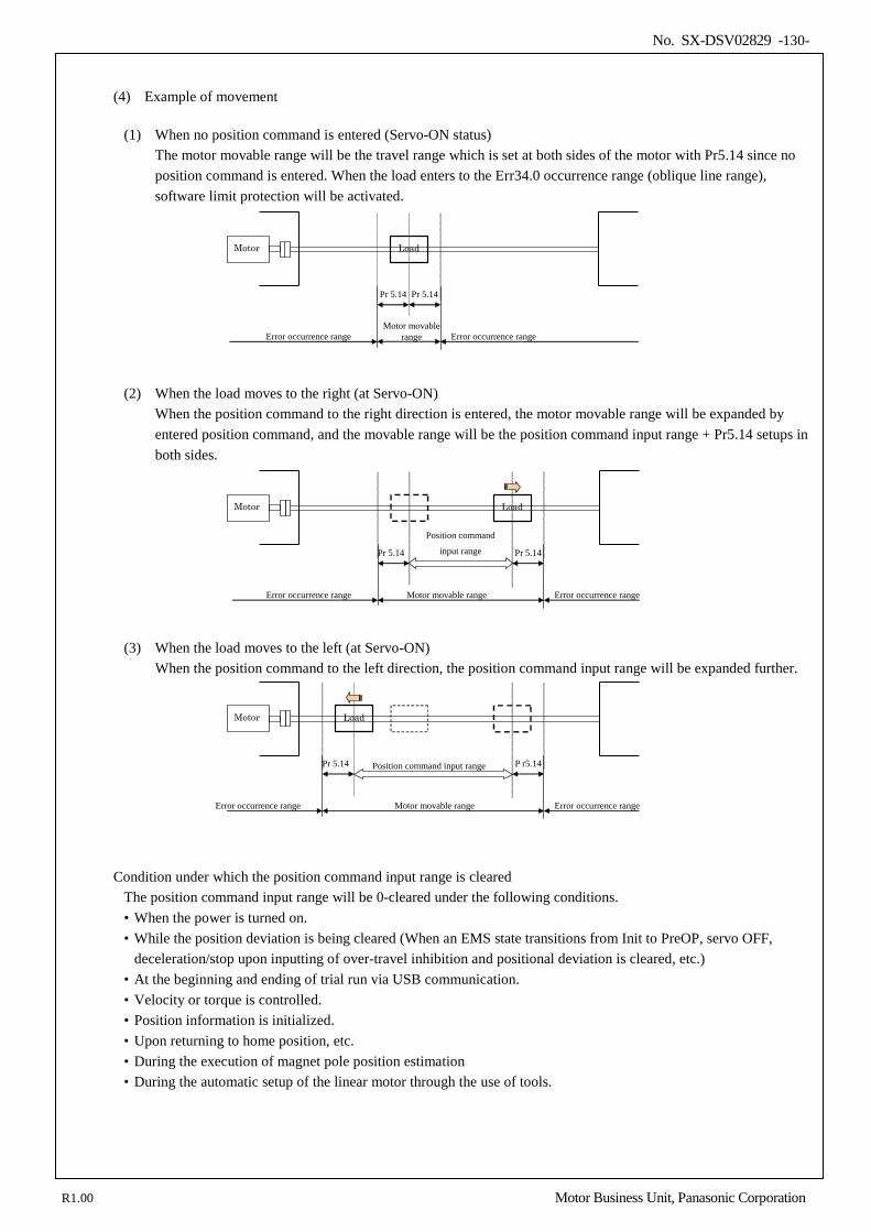
No. SX-DSV02829 -130-
(4) Example of movement
(1) When no position command is entered (Servo-ON status)
The motor movable range will be the travel range which is set at both sides of the motor with Pr5.14 since no position command is entered. When the load enters to the Err34.0 occurrence range (oblique line range), software limit protection will be activated.
Error occurrence range
Pr 5.14 Pr 5.14
Motor movable range Error occurrence range
Motor Load
(2) When the load moves to the right (at Servo-ON) When the position command to the right direction is entered, the motor movable range will be expanded by entered position command, and the movable range will be the position command input range + Pr5.14 setups in both sides.
Position command
input range Pr 5.14 Pr 5.14
Motor movable range Error occurrence range Error occurrence range
Motor Load
(3) When the load moves to the left (at Servo-ON) When the position command to the left direction, the position command input range will be expanded further.
Position command input range Pr 5.14 P r5.14
Motor movable range Error occurrence range Error occurrence range
Motor Load
Condition under which the position command input range is cleared The position command input range will be 0-cleared under the following conditions. • When the power is turned on. • While the position deviation is being cleared (When an EMS state transitions from Init to PreOP, servo OFF,
deceleration/stop upon inputting of over-travel inhibition and positional deviation is cleared, etc.) • At the beginning and ending of trial run via USB communication. • Velocity or torque is controlled. • Position information is initialized. • Upon returning to home position, etc. • During the execution of magnet pole position estimation • During the automatic setup of the linear motor through the use of tools.
R1.00 Motor Business Unit, Panasonic Corporation
No. SX-DSV02829 -131-
6-3 Deceleration stop sequence
Sets how to decelerate and stop the motor if main power is shut down or an alarm occurs while PDS is Operation enabled state (servo-on state). Combine the deceleration function (option code) defined by CoE(CiA402) and the deceleration function on the servo (MINAS-A5) side (dynamic brake stop, free-run stop, immediate stop). Please refer to section 6-9-2 "Option Code (deceleration stop sequence)" of Technical Document "EtherCAT Communication Specifications" (SX-DSV02830) for details.
6-3-1 Sequence upon inputting of over-travel inhibition (POT, NOT) (under review)
Set up the operating sequence when the over-travel inhibition is input (POT, NOT). Note) Set the over-travel inhibition input (POT, NOT) correctly.
If it is set incorrectly (NOT for the drive side in the positive direction, POT for the drive side in the negative direction, etc.), operations cannot be guaranteed.
(1) Parameters
Class No. At- trib-
ute *1) Title Range Unit Function
5 04 C Over-travel inhibit input
setup 0–2 —
Set up the operation of the run-inhibition (POT, NOT) inputs. Normally it should be set to 1. 0: Deceleration stop on servo (MINAS-A5) side (sequence at time of
run-inhibition input) POT → Positive direction over-travel inhibit, NOT → Negative direction over-travel inhibit. When POT is input during positive direction driving, stops the drive according to Pr 5.05 Sequence at over-travel inhibit. The similar function NOT is applied in reverse direction. Regardless of operating condition, torque in over-travel inhibition direction is 0. *2)
1: CoE (CiA402) side deceleration stop POT → Positive direction over-travel inhibit, NOT → Negative direction over-travel inhibit. When POT is input during positive direction driving, or NOT is input during Negative direction driving, EtherCAT profile slowdown defined
in CoE(CiA402) works and stops it. *2) The constants at the time of a slowdown differ for every control mode.
2: Deceleration stop on servo (MINAS-A5) side (sequence at time of alarm) POT or NOT input activates Err 38.0 Run-inhibition input protection.
5 05 *2)
C Sequence at over-travel
inhibit 0–2 —
When Pr 5.04 Over-travel inhibition = 0, specify the status during deceleration and stop after application of the over-travel inhibition (POT, NOT).
5 11 B Torque setup for emergency stop
0–500 % Set up the torque limit at emergency stop. When setup value is 0, the torque limit for normal operation is applied.
*1) For parameter attribute, refer to Section 9-1. *2) During magnet pole position estimation, and automatic linear motor setup, Err 38.0 “Run-inhibition input
protection“ is caused by the input of either of POT and NOT.
R1.00 Motor Business Unit, Panasonic Corporation
No. SX-DSV02829 -132-
(2) Contents
• Detail of deceleration stop on servo (MINAS-A5) side (sequence at time of run-inhibition input) (Pr5.04 = 0) Pr 5.04
*4) Pr 5.05
During deceleration *5) After stalling (Approx. 30 r/min or below) Stopping method Deviation Operation after stopping Deviation
0
Common
• Forcibly controls the position. *1) • Forcibly stops position command
generation. *1) • Bit 11(Internal limit active) of 6041h
(Statusword) is ON.
—
• Control mode depends on the command. *2)
• Bit 11(Internal limit active) of 6041h (Statusword) is ON.
—
0 • Dynamic brake action Clear *3) • Torque command=0
towards inhibited direction Hold
1 • Free run (DB OFF) Clear *3) • Torque command=0
towards inhibited direction Hold
2 • Emergency stop *4) • Torque limit=Pr 5.11
Clear *3) • Torque limit and torque
command are as usual. Hold
*1) During deceleration, the system is forced to perform position control, forcibly stopping the internal
position command generating process. *2) Stop a command in over-travel inhibit direction with the over-travel inhibit input set to ON. If a command
is issued in over-travel inhibit direction, the command is neglected. *3) During deviation clearing, the process that lets the internal command position to follow the feedback
position is activated. At the instantaneous stopping and at the end of deceleration, position deviations/feedback scale deviations accumulated during deceleration are cleared.
*4) Emergency stop refers to a controlled immediate stop with servo-on. The torque command value is limited during this process by Pr 5.11 Emergency stop torque setup.
In an emergency stop, normal operation is performed during the time between the input of the signal and the start of the emergency stop. If a positional command is stopped concurrently with the input of the signal, a torque disallowed by normal torque limitation may be output.
To allow a stop with the torque specified in the Emergency stop torque setup, continue to send the normal positional command at least 4 ms after the input of the signal.
*5) Deceleration period is the time required for the running motor to speed down to 30 r/min. Once the motor speed drops below 30 r/min, it is treated as in stop state regardless of its speed.
• Detail of CoE (CiA402) side deceleration stop (Pr5.04 = 1)
Pr5.04 control mode
*3) During deceleration *2) After stalling (about 30 or less r/min)
Stopping method Operation after a stopping
1
Common ・ Hold a servo-on condition. *4) ・ Bit 11(Internal limit active) of 6041h
(Statusword) is ON. *3)
・ Hold a servo-on condition. *4) ・ Bit 11(Internal limit active) of 6041h
(Statusword) is ON. *3) pp,pv,ip, csp,csv
Deceleration stop in 6085h(quick stop deceleration). ・ No command acceptance towards inhibited
direction *1) tq,cst Deceleration stop in 6087h(Torque slope).
*1) When the drive inhibit input of the ON state can stop a directive to towards inhibited direction.
If you give a command in the towards inhibited direction, the directive will be ignored. *2) Deceleration period is the time required for the running motor to speed down to 30 r/min. Once the motor
speed drops below 30 r/min, it is treated as in stop state regardless of its speed.
• In case of deceleration stop on servo (MINAS-A5) side (sequence at time of alarm) (Pr5.04 = 2) Err38.0 "Over-travel inhibit input protection" occurs when POT or NOT is turned on. Therefore, the system operates according to Sequence at alarm. but not to this setting.
R1.00 Motor Business Unit, Panasonic Corporation
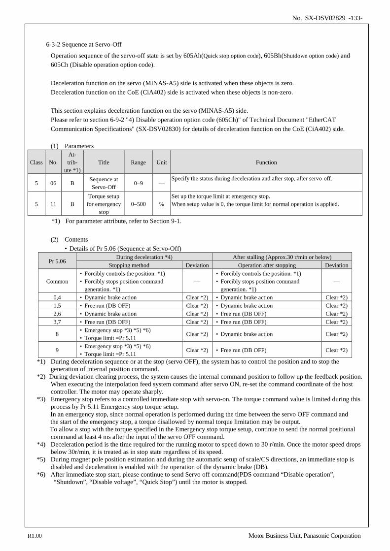
No. SX-DSV02829 -133-
6-3-2 Sequence at Servo-Off
Operation sequence of the servo-off state is set by 605Ah(Quick stop option code), 605Bh(Shutdown option code) and 605Ch (Disable operation option code). Deceleration function on the servo (MINAS-A5) side is activated when these objects is zero. Deceleration function on the CoE (CiA402) side is activated when these objects is non-zero. This section explains deceleration function on the servo (MINAS-A5) side. Please refer to section 6-9-2 "4) Disable operation option code (605Ch)" of Technical Document "EtherCAT Communication Specifications" (SX-DSV02830) for details of deceleration function on the CoE (CiA402) side. (1) Parameters
Class No. At- trib-
ute *1) Title Range Unit Function
5 06 B Sequence at Servo-Off
0–9 — Specify the status during deceleration and after stop, after servo-off.
5 11 B Torque setup
for emergency stop
0–500 % Set up the torque limit at emergency stop. When setup value is 0, the torque limit for normal operation is applied.
*1) For parameter attribute, refer to Section 9-1.
(2) Contents
• Details of Pr 5.06 (Sequence at Servo-Off)
Pr 5.06 During deceleration *4) After stalling (Approx.30 r/min or below)
Stopping method Deviation Operation after stopping Deviation
Common • Forcibly controls the position. *1) • Forcibly stops position command
generation. *1) —
• Forcibly controls the position. *1) • Forcibly stops position command
generation. *1) —
0,4 • Dynamic brake action Clear *2) • Dynamic brake action Clear *2) 1,5 • Free run (DB OFF) Clear *2) • Dynamic brake action Clear *2) 2,6 • Dynamic brake action Clear *2) • Free run (DB OFF) Clear *2) 3,7 • Free run (DB OFF) Clear *2) • Free run (DB OFF) Clear *2)
8 • Emergency stop *3) *5) *6) • Torque limit =Pr 5.11
Clear *2) • Dynamic brake action Clear *2)
9 • Emergency stop *3) *5) *6) • Torque limit =Pr 5.11
Clear *2) • Free run (DB OFF) Clear *2)
*1) During deceleration sequence or at the stop (servo OFF), the system has to control the position and to stop the generation of internal position command.
*2) During deviation clearing process, the system causes the internal command position to follow up the feedback position. When executing the interpolation feed system command after servo ON, re-set the command coordinate of the host controller. The motor may operate sharply.
*3) Emergency stop refers to a controlled immediate stop with servo-on. The torque command value is limited during this process by Pr 5.11 Emergency stop torque setup. In an emergency stop, since normal operation is performed during the time between the servo OFF command and the start of the emergency stop, a torque disallowed by normal torque limitation may be output.
To allow a stop with the torque specified in the Emergency stop torque setup, continue to send the normal positional command at least 4 ms after the input of the servo OFF command.
*4) Deceleration period is the time required for the running motor to speed down to 30 r/min. Once the motor speed drops below 30r/min, it is treated as in stop state regardless of its speed.
*5) During magnet pole position estimation and during the automatic setup of scale/CS directions, an immediate stop is disabled and deceleration is enabled with the operation of the dynamic brake (DB).
*6) After immediate stop start, please continue to send Servo off command(PDS command “Disable operation”, “Shutdown”, “Disable voltage”, “Quick Stop”) until the motor is stopped.
R1.00 Motor Business Unit, Panasonic Corporation
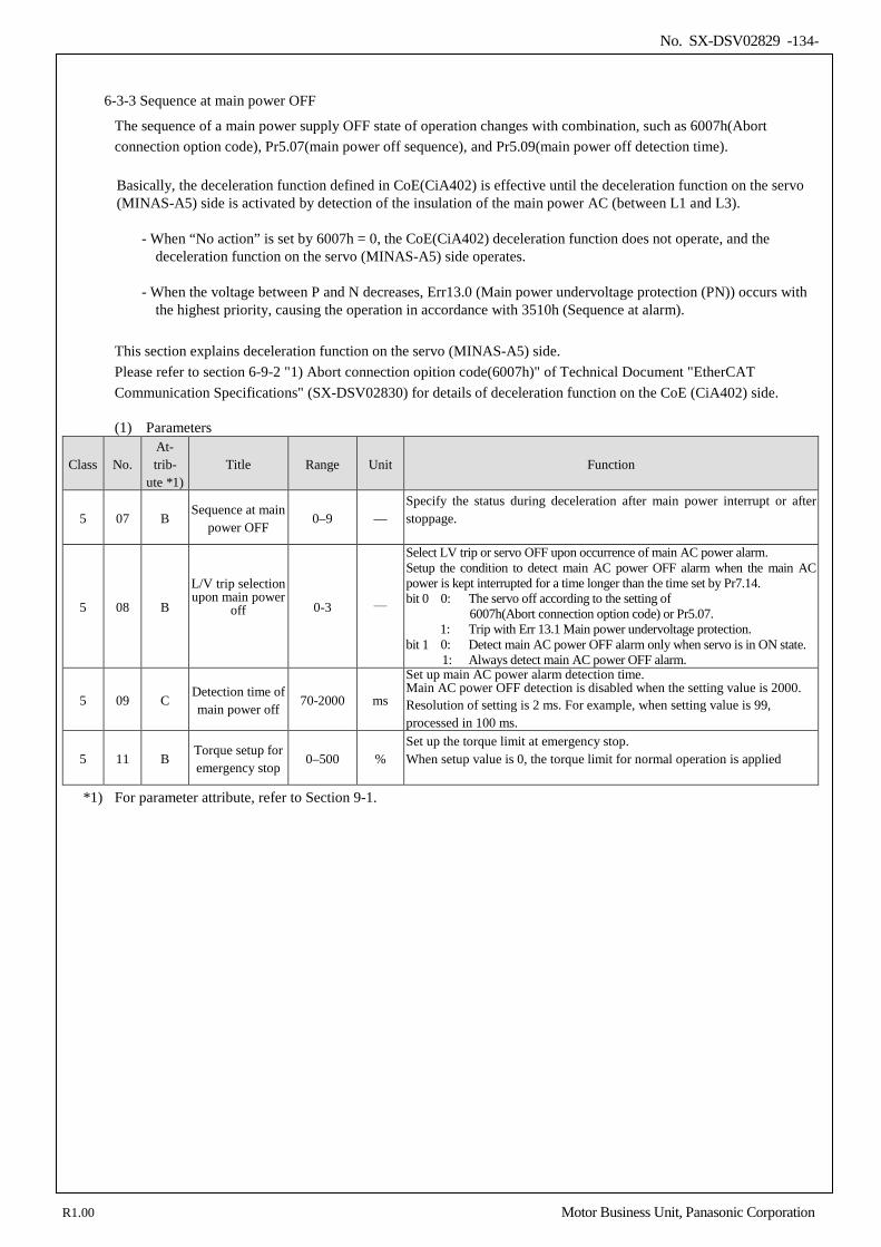
No. SX-DSV02829 -134-
6-3-3 Sequence at main power OFF
The sequence of a main power supply OFF state of operation changes with combination, such as 6007h(Abort connection option code), Pr5.07(main power off sequence), and Pr5.09(main power off detection time). Basically, the deceleration function defined in CoE(CiA402) is effective until the deceleration function on the servo (MINAS-A5) side is activated by detection of the insulation of the main power AC (between L1 and L3).
- When “No action” is set by 6007h = 0, the CoE(CiA402) deceleration function does not operate, and the
deceleration function on the servo (MINAS-A5) side operates.
- When the voltage between P and N decreases, Err13.0 (Main power undervoltage protection (PN)) occurs with the highest priority, causing the operation in accordance with 3510h (Sequence at alarm).
This section explains deceleration function on the servo (MINAS-A5) side. Please refer to section 6-9-2 "1) Abort connection opition code(6007h)" of Technical Document "EtherCAT Communication Specifications" (SX-DSV02830) for details of deceleration function on the CoE (CiA402) side.
(1) Parameters
Class No. At- trib-
ute *1) Title Range Unit Function
5 07 B Sequence at main
power OFF 0–9 —
Specify the status during deceleration after main power interrupt or after stoppage.
5 08 B
L/V trip selection upon main power
off
0-3 ―
Select LV trip or servo OFF upon occurrence of main AC power alarm. Setup the condition to detect main AC power OFF alarm when the main AC power is kept interrupted for a time longer than the time set by Pr7.14. bit 0 0: The servo off according to the setting of
6007h(Abort connection option code) or Pr5.07. 1: Trip with Err 13.1 Main power undervoltage protection. bit 1 0: Detect main AC power OFF alarm only when servo is in ON state.
1: Always detect main AC power OFF alarm.
5 09 C Detection time of main power off
70-2000 ms
Set up main AC power alarm detection time. Main AC power OFF detection is disabled when the setting value is 2000. Resolution of setting is 2 ms. For example, when setting value is 99, processed in 100 ms.
5 11 B Torque setup for emergency stop
0–500 % Set up the torque limit at emergency stop. When setup value is 0, the torque limit for normal operation is applied
*1) For parameter attribute, refer to Section 9-1.
R1.00 Motor Business Unit, Panasonic Corporation
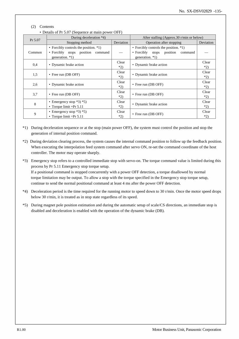
No. SX-DSV02829 -135-
(2) Contents
• Details of Pr 5.07 (Sequence at main power OFF)
Pr 5.07 During deceleration *4) After stalling (Approx.30 r/min or below)
Stopping method Deviation Operation after stopping Deviation
Common • Forcibly controls the position. *1) • Forcibly stops position command
generation. *1) —
• Forcibly controls the position. *1) • Forcibly stops position command
generation. *1) —
0,4 • Dynamic brake action Clear *2)
• Dynamic brake action Clear *2)
1,5 • Free run (DB OFF) Clear *2)
• Dynamic brake action Clear *2)
2,6 • Dynamic brake action Clear *2)
• Free run (DB OFF) Clear *2)
3,7 • Free run (DB OFF) Clear *2)
• Free run (DB OFF) Clear *2)
8 • Emergency stop *3) *5) • Torque limit =Pr 5.11
Clear *2)
• Dynamic brake action Clear *2)
9 • Emergency stop *3) *5) • Torque limit =Pr 5.11
Clear *2)
• Free run (DB OFF) Clear *2)
*1) During deceleration sequence or at the stop (main power OFF), the system must control the position and stop the
generation of internal position command.
*2) During deviation clearing process, the system causes the internal command position to follow up the feedback position. When executing the interpolation feed system command after servo ON, re-set the command coordinate of the host controller. The motor may operate sharply.
*3) Emergency stop refers to a controlled immediate stop with servo-on. The torque command value is limited during this process by Pr 5.11 Emergency stop torque setup. If a positional command is stopped concurrently with a power OFF detection, a torque disallowed by normal torque limitation may be output. To allow a stop with the torque specified in the Emergency stop torque setup, continue to send the normal positional command at least 4 ms after the power OFF detection.
*4) Deceleration period is the time required for the running motor to speed down to 30 r/min. Once the motor speed drops below 30 r/min, it is treated as in stop state regardless of its speed.
*5) During magnet pole position estimation and during the automatic setup of scale/CS directions, an immediate stop is disabled and deceleration is enabled with the operation of the dynamic brake (DB).
R1.00 Motor Business Unit, Panasonic Corporation
No. SX-DSV02829 -136-
6-3-4 Sequence at alarm
Set the operation sequence of the alarm status with the exception of the communication related alarm(Err80.*, Err81.*, Err85.*, Err88.*). Communication related alarms (Err80.*, Err81.*, Err85.*, Err88.*) information, set by 605Eh (Fault reaction option code). Please refer to section 6-9-2 "6) Fault reaction option code (605Eh)" of Technical Document "EtherCAT Communication Specifications" (SX-DSV02830) for details.
R1.00 Motor Business Unit, Panasonic Corporation
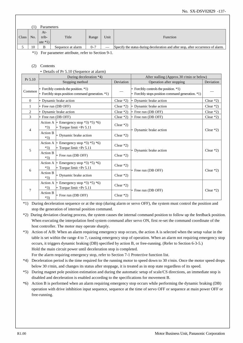
No. SX-DSV02829 -137-
(1) Parameters
Class No. At- trib-
ute *1) Title Range Unit Function
5 10 B Sequence at alarm 0–7 — Specify the status during deceleration and after stop, after occurrence of alarm. *1) For parameter attribute, refer to Section 9-1.
(2) Contents
• Details of Pr 5.10 (Sequence at alarm)
Pr 5.10 During deceleration *4) After stalling (Approx.30 r/min or below)
Stopping method Deviation Operation after stopping Deviation
Common • Forcibly controls the position. *1) • Forcibly stops position command generation. *1)
— • Forcibly controls the position. *1) • Forcibly stops position command generation. *1)
—
0 • Dynamic brake action Clear *2) • Dynamic brake action Clear *2) 1 • Free run (DB OFF) Clear *2) • Dynamic brake action Clear *2) 2 • Dynamic brake action Clear *2) • Free run (DB OFF) Clear *2) 3 • Free run (DB OFF) Clear *2) • Free run (DB OFF) Clear *2)
4
Action A *3)
• Emergency stop *3) *5) *6) • Torque limit =Pr 5.11
Clear *2) • Dynamic brake action Clear *2)
Action B *3)
• Dynamic brake action Clear *2)
5
Action A *3)
• Emergency stop *3) *5) *6) • Torque limit =Pr 5.11
Clear *2) • Dynamic brake action Clear *2)
Action B *3)
• Free run (DB OFF) Clear *2)
6
Action A *3)
• Emergency stop *3) *5) *6) • Torque limit =Pr 5.11
Clear *2) • Free run (DB OFF) Clear *2)
Action B *3)
• Dynamic brake action Clear *2)
7
Action A *3)
• Emergency stop *3) *5) *6) • Torque limit =Pr 5.11
Clear *2) • Free run (DB OFF) Clear *2)
Action B *3)
• Free run (DB OFF) Clear *2)
*1) During deceleration sequence or at the stop (during alarm or servo OFF), the system must control the position and stop the generation of internal position command.
*2) During deviation clearing process, the system causes the internal command position to follow up the feedback position. When executing the interpolation feed system command after servo ON, first re-set the command coordinate of the host controller. The motor may operate sharply.
*3) Action of A/B: When an alarm requiring emergency stop occurs, the action A is selected when the setup value in the table is set within the range 4 to 7, causing emergency stop of operation. When an alarm not requiring emergency stop occurs, it triggers dynamic braking (DB) specified by action B, or free-running. (Refer to Section 6-3-5.) Hold the main circuit power until deceleration stop is completed. For the alarm requiring emergency stop, refer to Section 7-1 Protective function list.
*4) Deceleration period is the time required for the running motor to speed down to 30 r/min. Once the motor speed drops below 30 r/min, and changes its status after stoppage, it is treated as in stop state regardless of its speed.
*5) During magnet pole position estimation and during the automatic setup of scale/CS directions, an immediate stop is disabled and deceleration is enabled according to the specifications for movement B.
*6) Action B is performed when an alarm requiring emergency stop occurs while performing the dynamic braking (DB) operation with drive inhibition input sequence, sequence at the time of servo OFF or sequence at main power OFF or free-running.
R1.00 Motor Business Unit, Panasonic Corporation
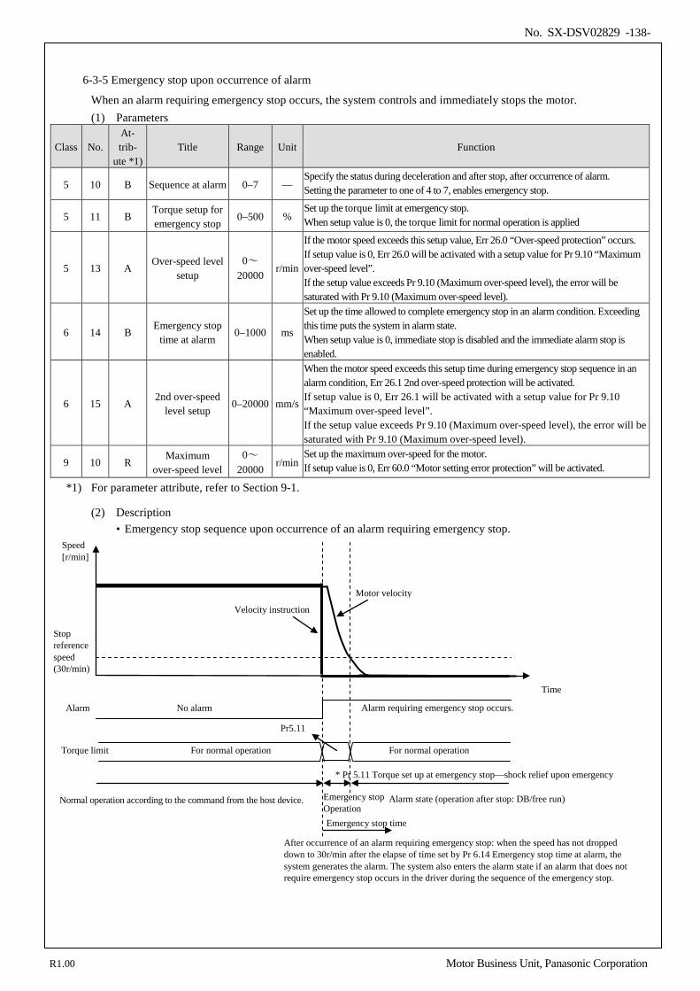
No. SX-DSV02829 -138-
6-3-5 Emergency stop upon occurrence of alarm
When an alarm requiring emergency stop occurs, the system controls and immediately stops the motor. (1) Parameters
Class No. At- trib-
ute *1) Title Range Unit Function
5 10 B Sequence at alarm 0–7 — Specify the status during deceleration and after stop, after occurrence of alarm. Setting the parameter to one of 4 to 7, enables emergency stop.
5 11 B Torque setup for emergency stop
0–500 % Set up the torque limit at emergency stop. When setup value is 0, the torque limit for normal operation is applied
5 13 A Over-speed level
setup 0~
20000 r/min
If the motor speed exceeds this setup value, Err 26.0 “Over-speed protection” occurs. If setup value is 0, Err 26.0 will be activated with a setup value for Pr 9.10 “Maximum over-speed level”. If the setup value exceeds Pr 9.10 (Maximum over-speed level), the error will be saturated with Pr 9.10 (Maximum over-speed level).
6 14 B Emergency stop
time at alarm 0–1000 ms
Set up the time allowed to complete emergency stop in an alarm condition. Exceeding this time puts the system in alarm state. When setup value is 0, immediate stop is disabled and the immediate alarm stop is enabled.
6 15 A 2nd over-speed
level setup 0–20000 mm/s
When the motor speed exceeds this setup time during emergency stop sequence in an alarm condition, Err 26.1 2nd over-speed protection will be activated. If setup value is 0, Err 26.1 will be activated with a setup value for Pr 9.10 “Maximum over-speed level”. If the setup value exceeds Pr 9.10 (Maximum over-speed level), the error will be saturated with Pr 9.10 (Maximum over-speed level).
9 10 R Maximum
over-speed level 0~
20000 r/min
Set up the maximum over-speed for the motor. If setup value is 0, Err 60.0 “Motor setting error protection” will be activated.
*1) For parameter attribute, refer to Section 9-1.
(2) Description • Emergency stop sequence upon occurrence of an alarm requiring emergency stop.
Torque limit
Speed [r/min]
Time
Alarm state (operation after stop: DB/free run) Emergency stop Operation
Normal operation according to the command from the host device.
Velocity instruction
Motor velocity
Pr5.11
For normal operation For normal operation
Alarm requiring emergency stop occurs. No alarm Alarm
Stop reference speed (30r/min)
After occurrence of an alarm requiring emergency stop: when the speed has not dropped down to 30r/min after the elapse of time set by Pr 6.14 Emergency stop time at alarm, the system generates the alarm. The system also enters the alarm state if an alarm that does not require emergency stop occurs in the driver during the sequence of the emergency stop.
Emergency stop time
* Pr 5.11 Torque set up at emergency stop—shock relief upon emergency stop
R1.00 Motor Business Unit, Panasonic Corporation
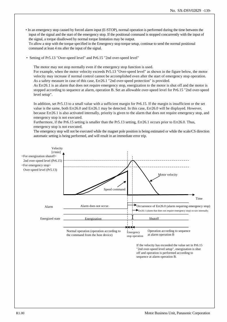
No. SX-DSV02829 -139-
• In an emergency stop caused by forced alarm input (E-STOP), normal operation is performed during the time between the input of the signal and the start of the emergency stop. If the positional command is stopped concurrently with the input of the signal, a torque disallowed by normal torque limitation may be output.
To allow a stop with the torque specified in the Emergency stop torque setup, continue to send the normal positional command at least 4 ms after the input of the signal.
• Setting of Pr5.13 "Over-speed level" and Pr6.15 "2nd over-speed level"
The motor may not stop normally even if the emergency stop function is used. For example, when the motor velocity exceeds Pr5.13 "Over-speed level" as shown in the figure below, the motor velocity may increase if normal control cannot be accomplished even after the start of emergency stop operation. As a safety measure in case of this case, Err26.1 "2nd over-speed protection" is provided. As Err26.1 is an alarm that does not require emergency stop, energization to the motor is shut off and the motor is stopped according to sequence at alarm, operation B. Set an allowable over-speed level for Pr6.15 "2nd over-speed level setup". In addition, set Pr5.13 to a small value with a sufficient margin for Pr6.15. If the margin is insufficient or the set value is the same, both Err26.0 and Err26.1 may be detected. In this case, Err26.0 will be displayed. However, because Err26.1 is also activated internally, priority is given to the alarm that does not require emergency stop, and emergency stop is not executed. Furthermore, if the Pr6.15 setting is smaller than the Pr5.13 setting, Err26.1 occurs prior to Err26.0. Thus, emergency stop is not executed. The emergency stop will not be executed while the magnet pole position is being estimated or while the scale/CS direction automatic setting is being performed, and will result in an immediate error trip.
Operation according to sequence at alarm operation B
Energized state
<For energization shutoff> <For emergency stop>
2nd over-speed level (Pr6.15)
Over-speed level (Pr5.13)
Occurrence of Err26.0 (alarm requiring emergency stop)
Emergency stop operation
Velocity [r/min]
If the velocity has exceeded the value set in Pr6.15 "2nd over-speed level setup", energization is shut off and operation is performed according to sequence at alarm operation B.
Time
Err26.1 (alarm that does not require emergency stop) occurs internally. Alarm
Normal operation (operation according to the command from the host device)
Speed command
Motor velocity
Shutoff Energization
Alarm does not occur.
R1.00 Motor Business Unit, Panasonic Corporation
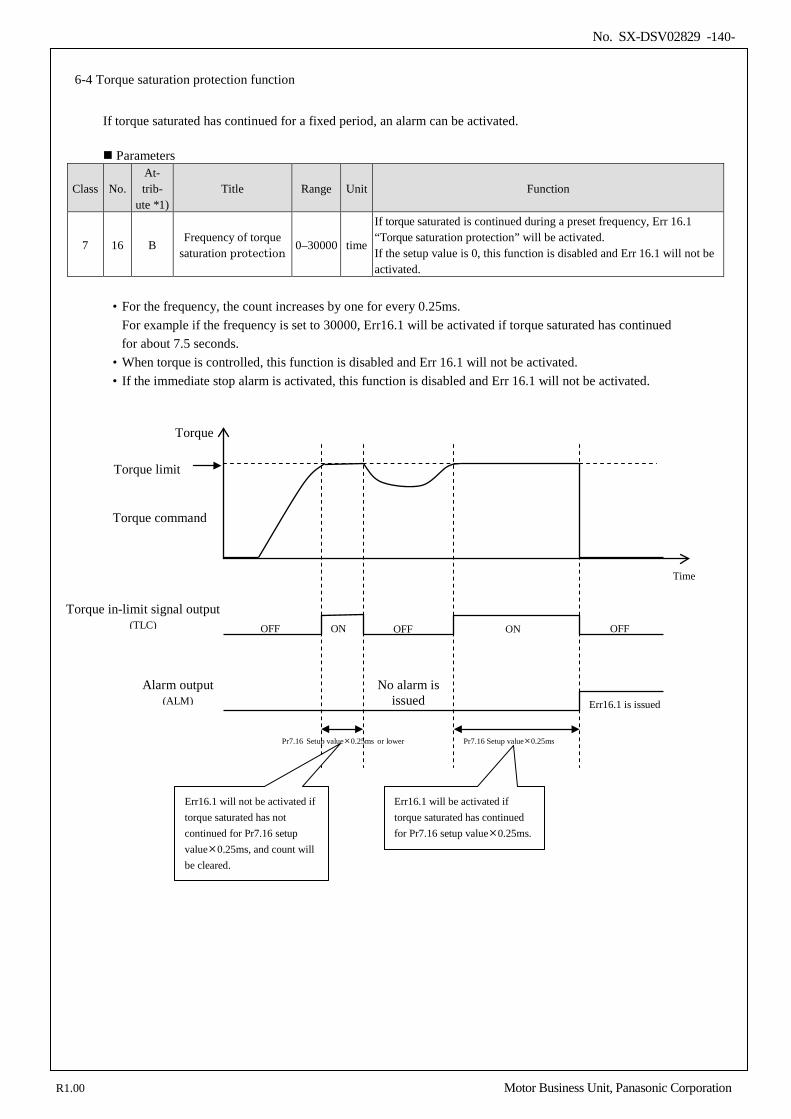
No. SX-DSV02829 -140-
6-4 Torque saturation protection function
If torque saturated has continued for a fixed period, an alarm can be activated. Parameters
Class No. At- trib-
ute *1) Title Range Unit Function
7 16 B Frequency of torque
saturation protection 0–30000 time
If torque saturated is continued during a preset frequency, Err 16.1 “Torque saturation protection” will be activated. If the setup value is 0, this function is disabled and Err 16.1 will not be activated.
• For the frequency, the count increases by one for every 0.25ms.
For example if the frequency is set to 30000, Err16.1 will be activated if torque saturated has continued for about 7.5 seconds.
• When torque is controlled, this function is disabled and Err 16.1 will not be activated. • If the immediate stop alarm is activated, this function is disabled and Err 16.1 will not be activated.
Torque command
Torque in-limit signal output (TLC)
Alarm output (ALM)
Err16.1 will not be activated if torque saturated has not continued for Pr7.16 setup value0.25ms, and count will be cleared.
Err16.1 will be activated if torque saturated has continued for Pr7.16 setup value0.25ms.
Err16.1 is issued
Pr7.16 Setup value0.25ms Pr7.16 Setup value0.25ms or lower
OFF OFF OFF ON ON
No alarm is issued
Time
Torque
Torque limit
R1.00 Motor Business Unit, Panasonic Corporation
No. SX-DSV02829 -141-
7.Protective function/Warning function 7-1 List of protective function ................................................................................................................................. 142 7-2 Details of Protective function ............................................................................................................................ 145 7-3 Warning function ............................................................................................................................................... 159 7-4 Setup of gain pre-adjustment protection ............................................................................................................ 162
7
R1.00 Motor Business Unit, Panasonic Corporation
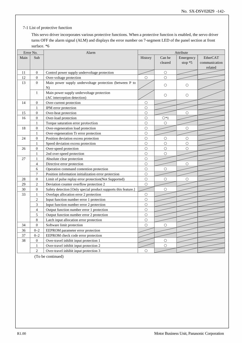
No. SX-DSV02829 -142-
7-1 List of protective function
This servo driver incorporates various protective functions. When a protective function is enabled, the servo driver turns OFF the alarm signal (ALM) and displays the error number on 7-segment LED of the panel section at front surface. *6
Error No. Alarm Attribute Main Sub History Can be
cleared Emergency
stop *5 EtherCAT
communication related
11 0 Control power supply undervoltage protection 12 0 Over-voltage protection 13 0 Main power supply undervoltage protection (between P to
N)
1 Main power supply undervoltage protection (AC interception detection)
14 0 Over-current protection 1 IPM error protection
15 0 Over-heat protection 16 0 Over-load protection *1
1 Torque saturation error protection 18 0 Over-regeneration load protection
1 Over-regeneration Tr error protection 24 0 Position deviation excess protection
1 Speed deviation excess protection 26 0 Over-speed protection
1 2nd over-speed protection 27 1 Absolute clear protection
4 Directive error protection 6 Operation command contention protection 7 Position information initialization error protection
28 0 Limit of pulse replay error protection(Not Supported) 29 2 Deviation counter overflow protection 2 30 0 Safety detection [Only special product supports this feature.] 33 1 Overlaps allocation error 2 protection
2 Input function number error 1 protection 3 Input function number error 2 protection 4 Output function number error 1 protection 5 Output function number error 2 protection 8 Latch input allocation error protection
34 0 Software limit protection 36 0–2 EEPROM parameter error protection 37 0–2 EEPROM check code error protection 38 0 Over-travel inhibit input protection 1
1 Over-travel inhibit input protection 2 2 Over-travel inhibit input protection 3
(To be continued)
R1.00 Motor Business Unit, Panasonic Corporation
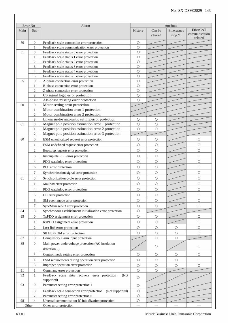
No. SX-DSV02829 -143-
Error No Alarm Attribute
Main Sub History Can be cleared
Emergency stop *6
EtherCAT communication
related 50 0 Feedback scale connection error protection
1 Feedback scale communication error protection 51 0 Feedback scale status 0 error protection
1 Feedback scale status 1 error protection 2 Feedback scale status 2 error protection 3 Feedback scale status 3 error protection 4 Feedback scale status 4 error protection 5 Feedback scale status 5 error protection
55 0 A-phase connection error protection 1 B-phase connection error protection 2 Z-phase connection error protection 3 CS signal logic error protection 4 AB-phase missing error protection
60 0 Motor setting error protection 1 Motor combination error 1 protection 2 Motor combination error 2 protection 3 Linear motor automatic setting error protection
61 0 Magnet pole position estimation error 1 protection 1 Magnet pole position estimation error 2 protection 2 Magnet pole position estimation error 3 protection
80 0 ESM unauthorized request error protection 1 ESM undefined request error protection 2 Bootstrap requests error protection 3 Incomplete PLL error protection 4 PDO watchdog error protection 6 PLL error protection 7 Synchronization signal error protection
81 0 Synchronization cycle error protection 1 Mailbox error protection 4 PDO watchdog error protection 5 DC error protection 6 SM event mode error protection 7 SyncManager2/3 error protection
84 3 Synchronous establishment initialization error protection 85 0 TxPDO assignment error protection
1 RxPDO assignment error protection 2 Lost link error protection 3 SII EEPROM error protection
87 0 Compulsory alarm input protection 88 0 Main power undervoltage protection (AC insulation
detection 2)
1 Control mode setting error protection 2 ESM requirements during operation error protection 3 Improper operation error protection
91 1 Command error protection 92 1 Feedback scale data recovery error protection (Not
supported)
93 0 Parameter setting error protection 1 3 Feedback scale connection error protection (Not supported) 7 Parameter setting error protection 5
98 4 Unusual communication IC initialization protection Other Other error protection — — — —
R1.00 Motor Business Unit, Panasonic Corporation
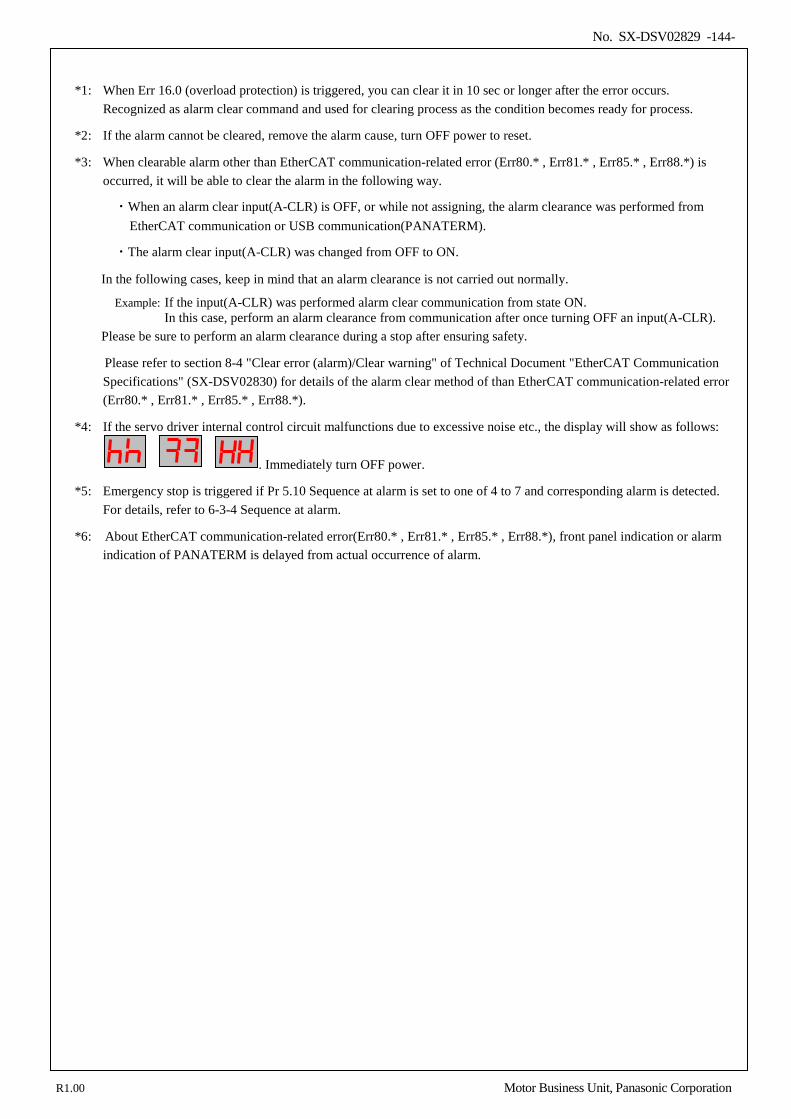
No. SX-DSV02829 -144-
*1: When Err 16.0 (overload protection) is triggered, you can clear it in 10 sec or longer after the error occurs.
Recognized as alarm clear command and used for clearing process as the condition becomes ready for process.
*2: If the alarm cannot be cleared, remove the alarm cause, turn OFF power to reset.
*3: When clearable alarm other than EtherCAT communication-related error (Err80.* , Err81.* , Err85.* , Err88.*) is occurred, it will be able to clear the alarm in the following way.
・When an alarm clear input(A-CLR) is OFF, or while not assigning, the alarm clearance was performed from EtherCAT communication or USB communication(PANATERM).
・The alarm clear input(A-CLR) was changed from OFF to ON.
In the following cases, keep in mind that an alarm clearance is not carried out normally.
Example: If the input(A-CLR) was performed alarm clear communication from state ON. In this case, perform an alarm clearance from communication after once turning OFF an input(A-CLR).
Please be sure to perform an alarm clearance during a stop after ensuring safety.
Please refer to section 8-4 "Clear error (alarm)/Clear warning" of Technical Document "EtherCAT Communication Specifications" (SX-DSV02830) for details of the alarm clear method of than EtherCAT communication-related error (Err80.* , Err81.* , Err85.* , Err88.*).
*4: If the servo driver internal control circuit malfunctions due to excessive noise etc., the display will show as follows:
. Immediately turn OFF power.
*5: Emergency stop is triggered if Pr 5.10 Sequence at alarm is set to one of 4 to 7 and corresponding alarm is detected. For details, refer to 6-3-4 Sequence at alarm.
*6: About EtherCAT communication-related error(Err80.* , Err81.* , Err85.* , Err88.*), front panel indication or alarm indication of PANATERM is delayed from actual occurrence of alarm.
R1.00 Motor Business Unit, Panasonic Corporation
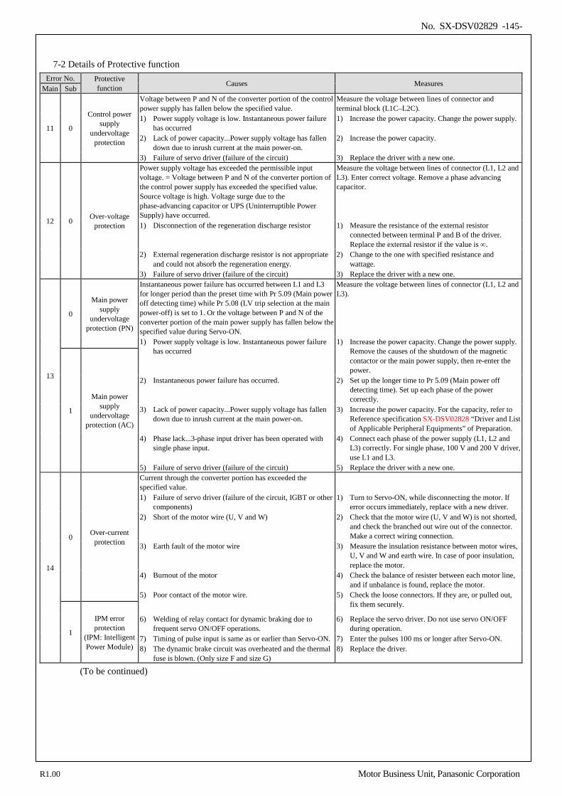
No. SX-DSV02829 -145-
7-2 Details of Protective function
Error No. Protective function Causes Measures
Main Sub
11 0
Control power supply
undervoltage protection
Voltage between P and N of the converter portion of the control power supply has fallen below the specified value.
Measure the voltage between lines of connector and terminal block (L1C–L2C).
1) Power supply voltage is low. Instantaneous power failure has occurred
1) Increase the power capacity. Change the power supply.
2) Lack of power capacity...Power supply voltage has fallen down due to inrush current at the main power-on.
2) Increase the power capacity.
3) Failure of servo driver (failure of the circuit) 3) Replace the driver with a new one.
12 0 Over-voltage protection
Power supply voltage has exceeded the permissible input voltage. = Voltage between P and N of the converter portion of the control power supply has exceeded the specified value. Source voltage is high. Voltage surge due to the phase-advancing capacitor or UPS (Uninterruptible Power Supply) have occurred.
Measure the voltage between lines of connector (L1, L2 and L3). Enter correct voltage. Remove a phase advancing capacitor.
1) Disconnection of the regeneration discharge resistor 1) Measure the resistance of the external resistor connected between terminal P and B of the driver. Replace the external resistor if the value is ∞.
2) External regeneration discharge resistor is not appropriate and could not absorb the regeneration energy.
2) Change to the one with specified resistance and wattage.
3) Failure of servo driver (failure of the circuit) 3) Replace the driver with a new one.
13
0
Main power supply
undervoltage protection (PN)
Instantaneous power failure has occurred between L1 and L3 for longer period than the preset time with Pr 5.09 (Main power off detecting time) while Pr 5.08 (LV trip selection at the main power-off) is set to 1. Or the voltage between P and N of the converter portion of the main power supply has fallen below the specified value during Servo-ON.
Measure the voltage between lines of connector (L1, L2 and L3).
1) Power supply voltage is low. Instantaneous power failure has occurred
1) Increase the power capacity. Change the power supply. Remove the causes of the shutdown of the magnetic contactor or the main power supply, then re-enter the power.
1
Main power supply
undervoltage protection (AC)
2) Instantaneous power failure has occurred. 2) Set up the longer time to Pr 5.09 (Main power off detecting time). Set up each phase of the power correctly.
3) Lack of power capacity...Power supply voltage has fallen down due to inrush current at the main power-on.
3) Increase the power capacity. For the capacity, refer to Reference specification SX-DSV02828 “Driver and List of Applicable Peripheral Equipments” of Preparation.
4) Phase lack...3-phase input driver has been operated with single phase input.
4) Connect each phase of the power supply (L1, L2 and L3) correctly. For single phase, 100 V and 200 V driver, use L1 and L3.
5) Failure of servo driver (failure of the circuit) 5) Replace the driver with a new one.
14
0 Over-current protection
Current through the converter portion has exceeded the specified value.
1) Failure of servo driver (failure of the circuit, IGBT or other components)
1) Turn to Servo-ON, while disconnecting the motor. If error occurs immediately, replace with a new driver.
2) Short of the motor wire (U, V and W) 2) Check that the motor wire (U, V and W) is not shorted, and check the branched out wire out of the connector. Make a correct wiring connection.
3) Earth fault of the motor wire 3) Measure the insulation resistance between motor wires, U, V and W and earth wire. In case of poor insulation, replace the motor.
4) Burnout of the motor 4) Check the balance of resister between each motor line, and if unbalance is found, replace the motor.
5) Poor contact of the motor wire. 5) Check the loose connectors. If they are, or pulled out, fix them securely.
1
IPM error protection
(IPM: Intelligent Power Module)
6) Welding of relay contact for dynamic braking due to frequent servo ON/OFF operations.
6) Replace the servo driver. Do not use servo ON/OFF during operation.
7) Timing of pulse input is same as or earlier than Servo-ON. 7) Enter the pulses 100 ms or longer after Servo-ON. 8) The dynamic brake circuit was overheated and the thermal
fuse is blown. (Only size F and size G) 8) Replace the driver.
(To be continued)
R1.00 Motor Business Unit, Panasonic Corporation
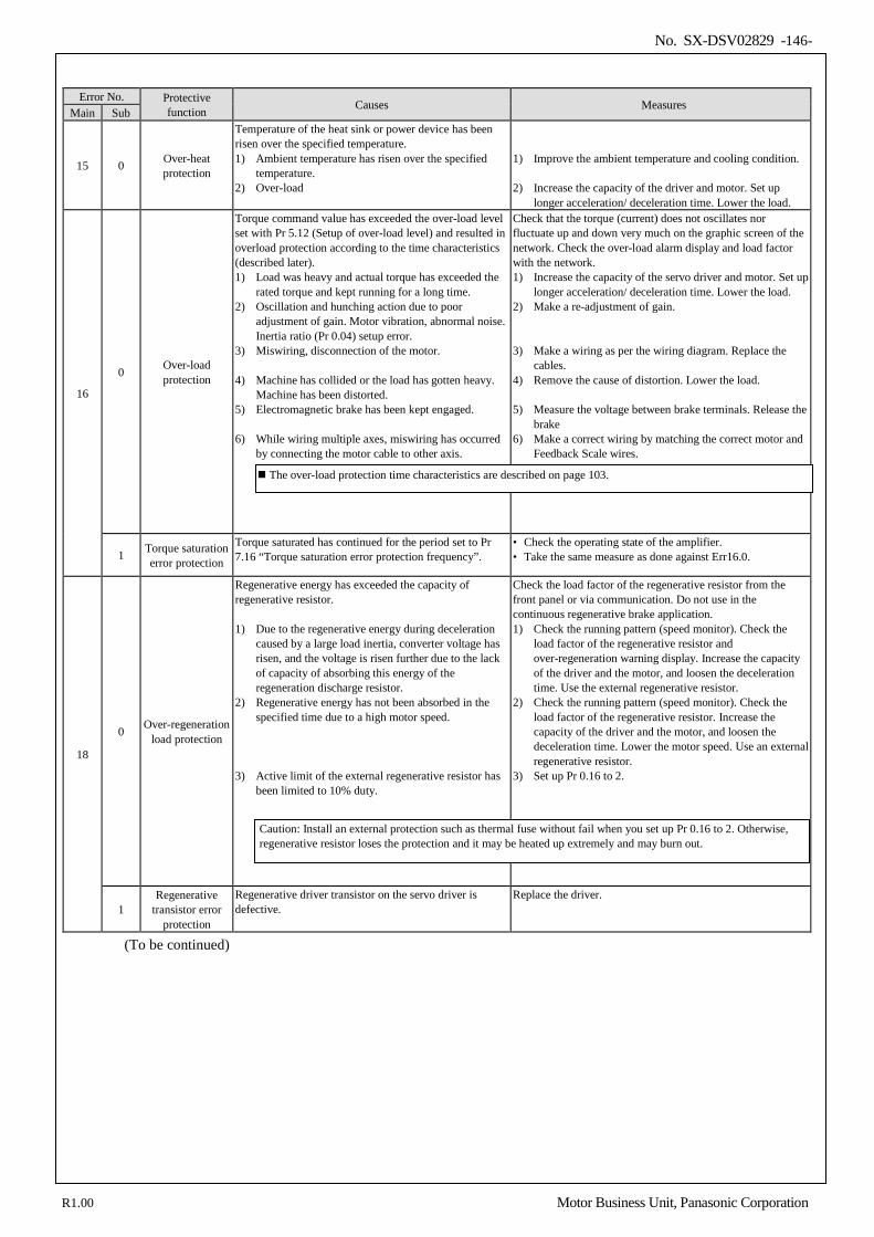
No. SX-DSV02829 -146-
Error No. Protective
function Causes Measures Main Sub
15 0 Over-heat protection
Temperature of the heat sink or power device has been risen over the specified temperature. 1) Ambient temperature has risen over the specified
temperature. 2) Over-load
1) Improve the ambient temperature and cooling condition.
2) Increase the capacity of the driver and motor. Set up
longer acceleration/ deceleration time. Lower the load.
16
0 Over-load protection
Torque command value has exceeded the over-load level set with Pr 5.12 (Setup of over-load level) and resulted in overload protection according to the time characteristics (described later). 1) Load was heavy and actual torque has exceeded the
rated torque and kept running for a long time. 2) Oscillation and hunching action due to poor
adjustment of gain. Motor vibration, abnormal noise. Inertia ratio (Pr 0.04) setup error.
3) Miswiring, disconnection of the motor. 4) Machine has collided or the load has gotten heavy.
Machine has been distorted. 5) Electromagnetic brake has been kept engaged. 6) While wiring multiple axes, miswiring has occurred
by connecting the motor cable to other axis.
Check that the torque (current) does not oscillates nor fluctuate up and down very much on the graphic screen of the network. Check the over-load alarm display and load factor with the network. 1) Increase the capacity of the servo driver and motor. Set up
longer acceleration/ deceleration time. Lower the load. 2) Make a re-adjustment of gain. 3) Make a wiring as per the wiring diagram. Replace the
cables. 4) Remove the cause of distortion. Lower the load. 5) Measure the voltage between brake terminals. Release the
brake 6) Make a correct wiring by matching the correct motor and
Feedback Scale wires.
1 Torque saturation error protection
Torque saturated has continued for the period set to Pr 7.16 “Torque saturation error protection frequency”.
• Check the operating state of the amplifier. • Take the same measure as done against Err16.0.
18
0 Over-regeneration load protection
Regenerative energy has exceeded the capacity of regenerative resistor. 1) Due to the regenerative energy during deceleration
caused by a large load inertia, converter voltage has risen, and the voltage is risen further due to the lack of capacity of absorbing this energy of the regeneration discharge resistor.
2) Regenerative energy has not been absorbed in the specified time due to a high motor speed.
3) Active limit of the external regenerative resistor has
been limited to 10% duty.
Check the load factor of the regenerative resistor from the front panel or via communication. Do not use in the continuous regenerative brake application. 1) Check the running pattern (speed monitor). Check the
load factor of the regenerative resistor and over-regeneration warning display. Increase the capacity of the driver and the motor, and loosen the deceleration time. Use the external regenerative resistor.
2) Check the running pattern (speed monitor). Check the load factor of the regenerative resistor. Increase the capacity of the driver and the motor, and loosen the deceleration time. Lower the motor speed. Use an external regenerative resistor.
3) Set up Pr 0.16 to 2.
1 Regenerative
transistor error protection
Regenerative driver transistor on the servo driver is defective.
Replace the driver.
(To be continued)
The over-load protection time characteristics are described on page 103.
Caution: Install an external protection such as thermal fuse without fail when you set up Pr 0.16 to 2. Otherwise, regenerative resistor loses the protection and it may be heated up extremely and may burn out.
R1.00 Motor Business Unit, Panasonic Corporation
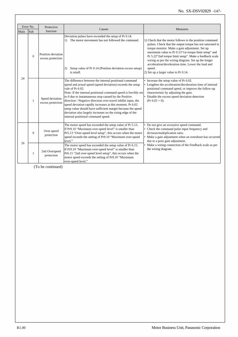
No. SX-DSV02829 -147-
Error No. Protective
function Causes Measures Main Sub
24
0 Position deviation excess protection
Deviation pulses have exceeded the setup of Pr 0.14. 1) The motor movement has not followed the command. 2) Setup value of Pr 0.14 (Position deviation excess setup)
is small.
1) Check that the motor follows to the position command
pulses. Check that the output torque has not saturated in torque monitor. Make a gain adjustment. Set up maximum value to Pr 0.13“1st torque limit setup“ and Pr 5.22“2nd torque limit setup“. Make a feedback scale wiring as per the wiring diagram. Set up the longer acceleration/deceleration time. Lower the load and speed.
2) Set up a larger value to Pr 0.14.
1 Speed deviation excess protection
The difference between the internal positional command speed and actual speed (speed deviation) exceeds the setup vale of Pr 6.02. Note: If the internal positional command speed is forcibly set to 0 due to instantaneous stop caused by the Positive direction / Negative direction over-travel inhibit input, the speed deviation rapidly increases at this moment. Pr 6.02 setup value should have sufficient margin because the speed deviation also largely increases on the rising edge of the internal positional command speed.
• Increase the setup value of Pr 6.02. • Lengthen the acceleration/deceleration time of internal
positional command speed, or improve the follow-up characteristic by adjusting the gain.
• Disable the excess speed deviation detection (Pr 6.02 = 0).
26
0 Over-speed protection
The motor speed has exceeded the setup value of Pr 5.13. If Pr9.10 “Maximum over-speed level” is smaller than Pr5.13 “Over-speed level setup”, this occurs when the motor speed exceeds the setting of Pr9.10 “Maximum over-speed level.”
• Do not give an excessive speed command. • Check the command pulse input frequency and
division/multiplication ratio. • Make a gain adjustment when an overshoot has occurred
due to a poor gain adjustment. • Make a wiring connection of the Feedback scale as per
the wiring diagram. 1 2nd Overspeed
protection
The motor speed has exceeded the setup value of Pr 6.15. If Pr9.10 “Maximum over-speed level” is smaller than Pr6.15 “2nd over-speed level setup”, this occurs when the motor speed exceeds the setting of Pr9.10 “Maximum over-speed level.”
(To be continued)
R1.00 Motor Business Unit, Panasonic Corporation
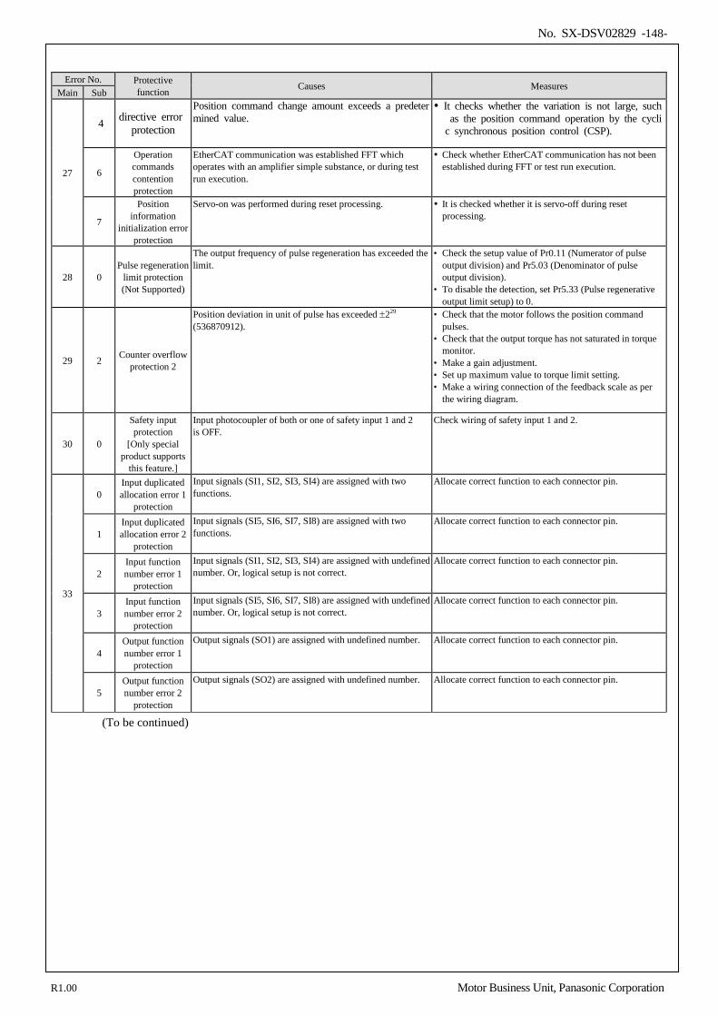
No. SX-DSV02829 -148-
Error No. Protective
function Causes Measures Main Sub
27
4 directive error protection
Position command change amount exceeds a predetermined value.
It checks whether the variation is not large, such as the position command operation by the cyclic synchronous position control (CSP).
6
Operation commands contention protection
EtherCAT communication was established FFT which operates with an amplifier simple substance, or during test run execution.
Check whether EtherCAT communication has not been established during FFT or test run execution.
7
Position information
initialization error protection
Servo-on was performed during reset processing. It is checked whether it is servo-off during reset processing.
28 0 Pulse regeneration
limit protection (Not Supported)
The output frequency of pulse regeneration has exceeded the limit.
• Check the setup value of Pr0.11 (Numerator of pulse output division) and Pr5.03 (Denominator of pulse output division).
• To disable the detection, set Pr5.33 (Pulse regenerative output limit setup) to 0.
29 2 Counter overflow protection 2
Position deviation in unit of pulse has exceeded ±229 (536870912).
• Check that the motor follows the position command pulses.
• Check that the output torque has not saturated in torque monitor.
• Make a gain adjustment. • Set up maximum value to torque limit setting. • Make a wiring connection of the feedback scale as per
the wiring diagram.
30 0
Safety input protection
[Only special product supports
this feature.]
Input photocoupler of both or one of safety input 1 and 2 is OFF.
Check wiring of safety input 1 and 2.
33
0 Input duplicated allocation error 1
protection
Input signals (SI1, SI2, SI3, SI4) are assigned with two functions.
Allocate correct function to each connector pin.
1 Input duplicated allocation error 2
protection
Input signals (SI5, SI6, SI7, SI8) are assigned with two functions.
Allocate correct function to each connector pin.
2 Input function number error 1
protection
Input signals (SI1, SI2, SI3, SI4) are assigned with undefined number. Or, logical setup is not correct.
Allocate correct function to each connector pin.
3 Input function number error 2
protection
Input signals (SI5, SI6, SI7, SI8) are assigned with undefined number. Or, logical setup is not correct.
Allocate correct function to each connector pin.
4 Output function number error 1
protection
Output signals (SO1) are assigned with undefined number. Allocate correct function to each connector pin.
5 Output function number error 2
protection
Output signals (SO2) are assigned with undefined number. Allocate correct function to each connector pin.
(To be continued)
R1.00 Motor Business Unit, Panasonic Corporation
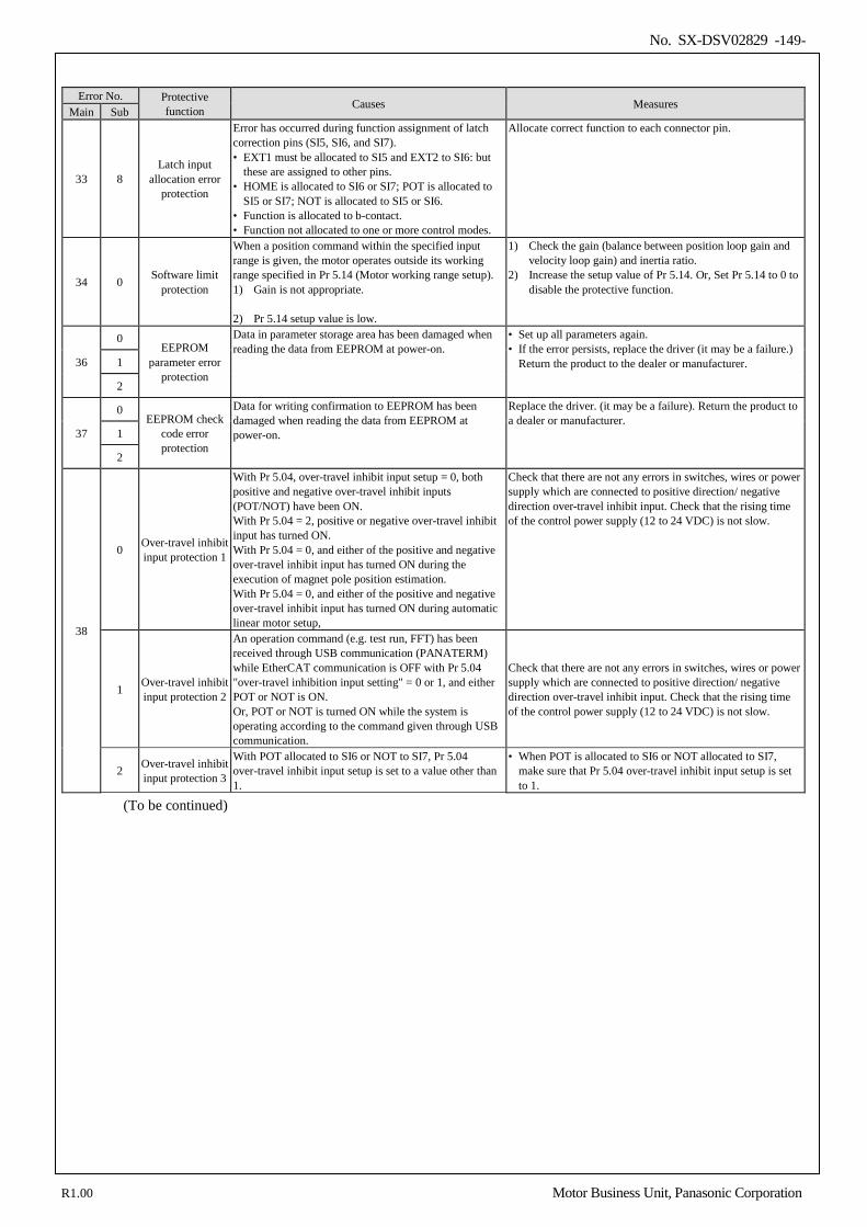
No. SX-DSV02829 -149-
Error No. Protective
function Causes Measures Main Sub
33 8 Latch input
allocation error protection
Error has occurred during function assignment of latch correction pins (SI5, SI6, and SI7). • EXT1 must be allocated to SI5 and EXT2 to SI6: but
these are assigned to other pins. • HOME is allocated to SI6 or SI7; POT is allocated to
SI5 or SI7; NOT is allocated to SI5 or SI6. • Function is allocated to b-contact. • Function not allocated to one or more control modes.
Allocate correct function to each connector pin.
34 0 Software limit protection
When a position command within the specified input range is given, the motor operates outside its working range specified in Pr 5.14 (Motor working range setup). 1) Gain is not appropriate. 2) Pr 5.14 setup value is low.
1) Check the gain (balance between position loop gain and velocity loop gain) and inertia ratio.
2) Increase the setup value of Pr 5.14. Or, Set Pr 5.14 to 0 to disable the protective function.
36
0 EEPROM
parameter error protection
Data in parameter storage area has been damaged when reading the data from EEPROM at power-on.
• Set up all parameters again. • If the error persists, replace the driver (it may be a failure.)
Return the product to the dealer or manufacturer. 1
2
37
0 EEPROM check
code error protection
Data for writing confirmation to EEPROM has been damaged when reading the data from EEPROM at power-on.
Replace the driver. (it may be a failure). Return the product to a dealer or manufacturer.
1
2
38
0 Over-travel inhibit input protection 1
With Pr 5.04, over-travel inhibit input setup = 0, both positive and negative over-travel inhibit inputs (POT/NOT) have been ON. With Pr 5.04 = 2, positive or negative over-travel inhibit input has turned ON. With Pr 5.04 = 0, and either of the positive and negative over-travel inhibit input has turned ON during the execution of magnet pole position estimation. With Pr 5.04 = 0, and either of the positive and negative over-travel inhibit input has turned ON during automatic linear motor setup,
Check that there are not any errors in switches, wires or power supply which are connected to positive direction/ negative direction over-travel inhibit input. Check that the rising time of the control power supply (12 to 24 VDC) is not slow.
1 Over-travel inhibit input protection 2
An operation command (e.g. test run, FFT) has been received through USB communication (PANATERM) while EtherCAT communication is OFF with Pr 5.04 "over-travel inhibition input setting" = 0 or 1, and either POT or NOT is ON. Or, POT or NOT is turned ON while the system is operating according to the command given through USB communication.
Check that there are not any errors in switches, wires or power supply which are connected to positive direction/ negative direction over-travel inhibit input. Check that the rising time of the control power supply (12 to 24 VDC) is not slow.
2 Over-travel inhibit input protection 3
With POT allocated to SI6 or NOT to SI7, Pr 5.04 over-travel inhibit input setup is set to a value other than 1.
• When POT is allocated to SI6 or NOT allocated to SI7, make sure that Pr 5.04 over-travel inhibit input setup is set to 1.
(To be continued)
R1.00 Motor Business Unit, Panasonic Corporation
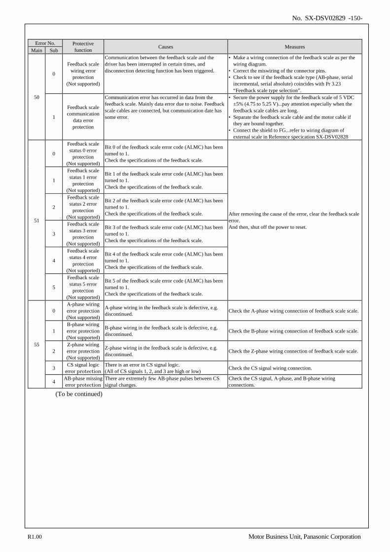
No. SX-DSV02829 -150-
Error No. Protective
function Causes Measures Main Sub
50
0
Feedback scale wiring error protection
(Not supported)
Communication between the feedback scale and the driver has been interrupted in certain times, and disconnection detecting function has been triggered.
• Make a wiring connection of the feedback scale as per the wiring diagram.
• Correct the miswiring of the connector pins. • Check to see if the feedback scale type (AB-phase, serial
incremental, serial absolute) coincides with Pr 3.23 “Feedback scale type selection”.
1
Feedback scale communication
data error protection
Communication error has occurred in data from the feedback scale. Mainly data error due to noise. Feedback scale cables are connected, but communication date has some error.
• Secure the power supply for the feedback scale of 5 VDC ±5% (4.75 to 5.25 V)...pay attention especially when the feedback scale cables are long.
• Separate the feedback scale cable and the motor cable if they are bound together.
• Connect the shield to FG...refer to wiring diagram of external scale in Reference specication SX-DSV02828
51
0
Feedback scale status 0 error
protection (Not supported)
Bit 0 of the feedback scale error code (ALMC) has been turned to 1. Check the specifications of the feedback scale.
After removing the cause of the error, clear the feedback scale error. And then, shut off the power to reset.
1
Feedback scale status 1 error
protection (Not supported)
Bit 1 of the feedback scale error code (ALMC) has been turned to 1. Check the specifications of the feedback scale.
2
Feedback scale status 2 error
protection (Not supported)
Bit 2 of the feedback scale error code (ALMC) has been turned to 1. Check the specifications of the feedback scale.
3
Feedback scale status 3 error
protection (Not supported)
Bit 3 of the feedback scale error code (ALMC) has been turned to 1. Check the specifications of the feedback scale.
4
Feedback scale status 4 error
protection (Not supported)
Bit 4 of the feedback scale error code (ALMC) has been turned to 1. Check the specifications of the feedback scale.
5
Feedback scale status 5 error
protection (Not supported)
Bit 5 of the feedback scale error code (ALMC) has been turned to 1. Check the specifications of the feedback scale.
55
0 A-phase wiring error protection (Not supported)
A-phase wiring in the feedback scale is defective, e.g. discontinued. Check the A-phase wiring connection of feedback scale scale.
1 B-phase wiring error protection (Not supported)
B-phase wiring in the feedback scale is defective, e.g. discontinued. Check the B-phase wiring connection of feedback scale scale.
2 Z-phase wiring error protection (Not supported)
Z-phase wiring in the feedback scale is defective, e.g. discontinued. Check the Z-phase wiring connection of feedback scale scale.
3 CS signal logic error protection
There is an error in CS signal logic. (All of CS signals 1, 2, and 3 are high or low) Check the CS signal wiring connection.
4 AB-phase missing error protection
There are extremely few AB-phase pulses between CS signal changes.
Check the CS signal, A-phase, and B-phase wiring connections.
(To be continued)
R1.00 Motor Business Unit, Panasonic Corporation
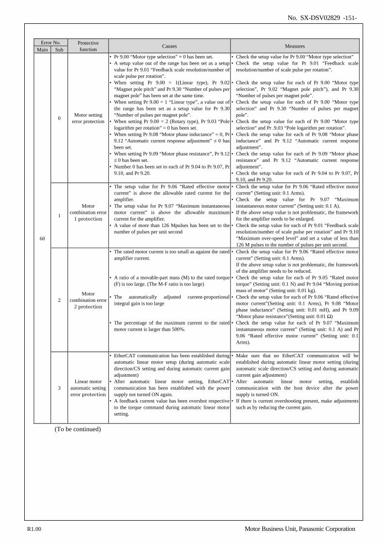
No. SX-DSV02829 -151-
Error No. Protective
function Causes Measures Main Sub
60
0 Motor setting error protection
• Pr 9.00 “Motor type selection” = 0 has been set. • A setup value out of the range has been set as a setup
value for Pr 9.01 “Feedback scale resolution/number of scale pulse per rotation”.
• When setting Pr 9.00 = 1(Linear type), Pr 9.02 “Magnet pole pitch” and Pr 9.30 “Number of pulses per magnet pole” has been set at the same time.
• When setting Pr 9.00 = 1 “Linear type”, a value out of the range has been set as a setup value for Pr 9.30 “Number of pulses per magnet pole”.
• When setting Pr 9.00 = 2 (Rotary type), Pr 9.03 “Pole logarithm per rotation” = 0 has been set.
• When setting Pr 9.08 “Motor phase inductance” = 0, Pr 9.12 “Automatic current response adjustment” ≠ 0 has been set.
• When setting Pr 9.09 “Motor phase resistance”, Pr 9.12 ≠ 0 has been set.
• Number 0 has been set to each of Pr 9.04 to Pr 9.07, Pr 9.10, and Pr 9.20.
• Check the setup value for Pr 9.00 “Motor type selection” • Check the setup value for Pr 9.01 “Feedback scale
resolution/number of scale pulse per rotation”. • Check the setup value for each of Pr 9.00 “Motor type
selection”, Pr 9.02 “Magnet pole pitch”), and Pr 9.30 “Number of pulses per magnet pole”.
• Check the setup value for each of Pr 9.00 “Motor type selection“ and Pr 9.30 “Number of pulses per magnet pole”.
• Check the setup value for each of Pr 9.00 “Motor type selection“ and Pr .9.03 “Pole logarithm per rotation”.
• Check the setup value for each of Pr 9.08 “Motor phase inductance” and Pr 9.12 “Automatic current response adjustment”.
• Check the setup value for each of Pr 9.09 “Motor phase resistance” and Pr 9.12 “Automatic current response adjustment”.
• Check the setup value for each of Pr 9.04 to Pr 9.07, Pr 9.10, and Pr 9.20.
1
Motor combination error
1 protection
• The setup value for Pr 9.06 “Rated effective motor current” is above the allowable rated current for the amplifier.
• The setup value for Pr 9.07 “Maximum instantaneous motor current” is above the allowable maximum current for the amplifier.
• A value of more than 126 Mpulses has been set to the number of pulses per unit second
• Check the setup value for Pr 9.06 “Rated effective motor current” (Setting unit: 0.1 Arms).
• Check the setup value for Pr 9.07 “Maximum instantaneous motor current” (Setting unit: 0.1 A).
• If the above setup value is not problematic, the framework for the amplifier needs to be enlarged.
• Check the setup value for each of Pr 9.01 “Feedback scale resolution/number of scale pulse per rotation” and Pr 9.10 “Maximum over-speed level” and set a value of less than 126 M pulses to the number of pulses per unit second.
2 Motor
combination error 2 protection
• The rated motor current is too small as against the rated amplifier current.
• A ratio of a movable-part mass (M) to the rated torque
(F) is too large. (The M-F ratio is too large) • The automatically adjusted current-proportional
integral gain is too large • The percentage of the maximum current to the rated
motor current is larger than 500%.
• Check the setup value for Pr 9.06 “Rated effective motor current” (Setting unit: 0.1 Arms). If the above setup value is not problematic, the framework of the amplifier needs to be reduced.
• Check the setup value for each of Pr 9.05 “Rated motor torque” (Setting unit: 0.1 N) and Pr 9.04 “Moving portion mass of motor” (Setting unit: 0.01 kg).
• Check the setup value for each of Pr 9.06 “Rated effective motor current”(Setting unit: 0.1 Arms), Pr 9.08 “Motor phase inductance” (Setting unit: 0.01 mH), and Pr 9.09 “Motor phase resistance”(Setting unit: 0.01 Ω)
• Check the setup value for each of Pr 9.07 “Maximum instantaneous motor current” (Setting unit: 0.1 A) and Pr 9.06 “Rated effective motor current” (Setting unit: 0.1 Arms).
3 Linear motor
automatic setting error protection
• EtherCAT communication has been established during automatic linear motor setup (during automatic scale direction/CS setting and during automatic current gain adjustment)
• After automatic linear motor setting, EtherCAT communication has been established with the power supply not turned ON again.
• A feedback current value has been overshot respective to the torque command during automatic linear motor setting.
• Make sure that no EtherCAT communication will be established during automatic linear motor setting (during automatic scale direction/CS setting and during automatic current gain adjustment)
• After automatic linear motor setting, establish communication with the host device after the power supply is turned ON.
• If there is current overshooting present, make adjustments such as by reducing the current gain.
(To be continued)
R1.00 Motor Business Unit, Panasonic Corporation
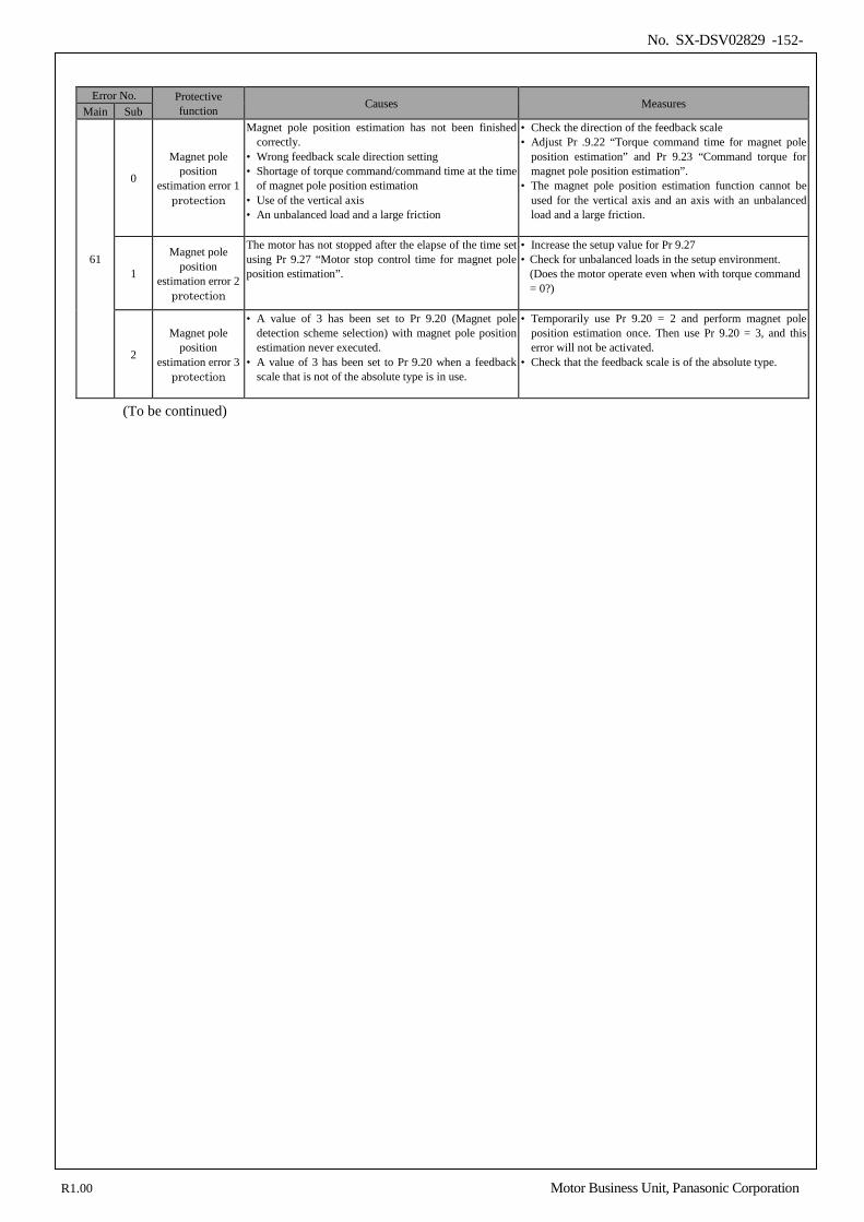
No. SX-DSV02829 -152-
Error No. Protective
function Causes Measures Main Sub
61
0
Magnet pole position
estimation error 1 protection
Magnet pole position estimation has not been finished correctly.
• Wrong feedback scale direction setting • Shortage of torque command/command time at the time
of magnet pole position estimation • Use of the vertical axis • An unbalanced load and a large friction
• Check the direction of the feedback scale • Adjust Pr .9.22 “Torque command time for magnet pole
position estimation” and Pr 9.23 “Command torque for magnet pole position estimation”.
• The magnet pole position estimation function cannot be used for the vertical axis and an axis with an unbalanced load and a large friction.
1
Magnet pole position
estimation error 2 protection
The motor has not stopped after the elapse of the time set using Pr 9.27 “Motor stop control time for magnet pole position estimation”.
• Increase the setup value for Pr 9.27 • Check for unbalanced loads in the setup environment.
(Does the motor operate even when with torque command = 0?)
2
Magnet pole position
estimation error 3 protection
• A value of 3 has been set to Pr 9.20 (Magnet pole detection scheme selection) with magnet pole position estimation never executed.
• A value of 3 has been set to Pr 9.20 when a feedback scale that is not of the absolute type is in use.
• Temporarily use Pr 9.20 = 2 and perform magnet pole position estimation once. Then use Pr 9.20 = 3, and this error will not be activated.
• Check that the feedback scale is of the absolute type.
(To be continued)
R1.00 Motor Business Unit, Panasonic Corporation
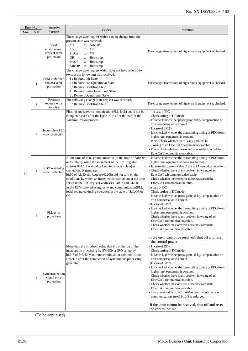
No. SX-DSV02829 -153-
Error No. Protective
function Causes Measures Main Sub
80
0
ESM unauthorized request error
protection
The change state request which cannot change from the present state was received. Init to SafeOP Init to OP PreOP to OP OP to Bootstrap PreOP to Bootstrap SafeOP to Bootstrap
The change state request of higher rank equipment is checked.
1 ESM undefined
request error protection
The change state request which does not have a definition (except the following) was received. 1 : Request Init State 2 : Request Pre-Operational State 3 : Request Bootstrap State 4 : Request Safe-Operational State 8 : Request Operational State
The change state request of higher rank equipment is checked.
2 Bootstrap
requests error protection
The following change state request was received. 3 : Request Bootstrap State The change state request of higher rank equipment is checked.
3 Incomplete PLL error protection
Phasing and servo communication(PLL lock) could not be completed even after the lapse of 1s after the start of the synchronization process.
<In case of DC> - Check setting of DC mode. - It is checked whether propagation delay compensation or
drift compensation is correct. <In case of SM2> - It is checked whether the transmitting timing of PDO from
higher rank equipment is constant. - Please check whether there is any problem in
wiring of an EtherCAT communication cable. - Please check whether the excessive noise has started the
EtherCAT communication cable.
4 PDO watchdog error protection
At the time of PDO communication (at the time of SafeOP or OP state), when the increment of the ESC register address 0442h (Watchdog Counter Process Data) is carried out, it generates. bit10 of AL Event Request(0220h) did not turn on the conditions by which an increment is carried out at the time set up in the ESC register addresses 0400h and 0420h.
- It is checked whether the transmitting timing of PDO from higher rank equipment is constant(not stop).
- Increase the timeout value of the PDO watchdog detection. - Check whether there is any problem in wiring of an
EtherCAT telecommunication cable. - Check whether the excessive noise has started the
EtherCAT communication cable.
6 PLL error protection
In the ESM state, phasing servo and communication(PLL lock) separated during operation in the state of SafeOP or OP.
<In case of DC> - Check setting of DC mode. - It is checked whether propagation delay compensation or
drift compensation is correct. <In case of SM2> - It is checked whether the transmitting timing of PDO from
higher rank equipment is constant. - Check whether there is any problem in wiring of an
EtherCAT communication cable. - Check whether the excessive noise has started the
EtherCAT communication cable. - If the error cannot be resolved, shut off and reset
the control power.
7 Synchronization
signal error protection
More than the threshold value that the omission of the interruption processing by SYNC0 or IRQ set up by bit0-3 of Pr7.42(Maximum continuation communication error) in after the completion of synchronous processing generated.
<In case of DC> - Check setting of DC mode. - It is checked whether propagation delay compensation or
drift compensation is correct. <In case of SM2> - It is checked whether the transmitting timing of PDO from
higher rank equipment is constant. - Check whether there is any problem in wiring of an
EtherCAT communication cable. - Check whether the excessive noise has started the
EtherCAT communication cable. - The preset value of Pr7.42(Maximum continuation
communication error) bit0-3 is enlarged. - If the error cannot be resolved, shut off and reset the control power.
(To be continued)
R1.00 Motor Business Unit, Panasonic Corporation
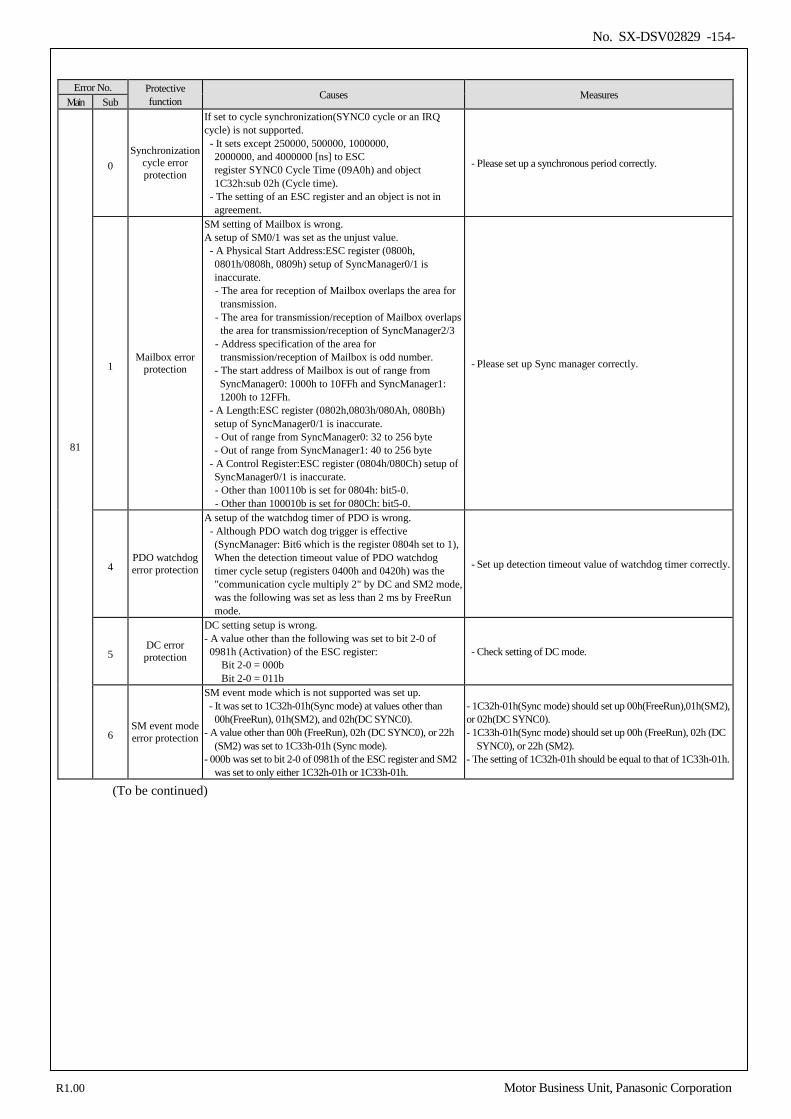
No. SX-DSV02829 -154-
Error No. Protective
function Causes Measures Main Sub
81
0 Synchronization
cycle error protection
If set to cycle synchronization(SYNC0 cycle or an IRQ cycle) is not supported. - It sets except 250000, 500000, 1000000,
2000000, and 4000000 [ns] to ESC register SYNC0 Cycle Time (09A0h) and object 1C32h:sub 02h (Cycle time).
- The setting of an ESC register and an object is not in agreement.
- Please set up a synchronous period correctly.
1 Mailbox error
protection
SM setting of Mailbox is wrong. A setup of SM0/1 was set as the unjust value. - A Physical Start Address:ESC register (0800h,
0801h/0808h, 0809h) setup of SyncManager0/1 is inaccurate. - The area for reception of Mailbox overlaps the area for transmission. - The area for transmission/reception of Mailbox overlaps the area for transmission/reception of SyncManager2/3 - Address specification of the area for transmission/reception of Mailbox is odd number. - The start address of Mailbox is out of range from SyncManager0: 1000h to 10FFh and SyncManager1: 1200h to 12FFh.
- A Length:ESC register (0802h,0803h/080Ah, 080Bh) setup of SyncManager0/1 is inaccurate. - Out of range from SyncManager0: 32 to 256 byte - Out of range from SyncManager1: 40 to 256 byte
- A Control Register:ESC register (0804h/080Ch) setup of SyncManager0/1 is inaccurate. - Other than 100110b is set for 0804h: bit5-0. - Other than 100010b is set for 080Ch: bit5-0.
- Please set up Sync manager correctly.
4 PDO watchdog error protection
A setup of the watchdog timer of PDO is wrong. - Although PDO watch dog trigger is effective
(SyncManager: Bit6 which is the register 0804h set to 1), When the detection timeout value of PDO watchdog timer cycle setup (registers 0400h and 0420h) was the "communication cycle multiply 2" by DC and SM2 mode, was the following was set as less than 2 ms by FreeRun mode.
- Set up detection timeout value of watchdog timer correctly.
5 DC error protection
DC setting setup is wrong. - A value other than the following was set to bit 2-0 of 0981h (Activation) of the ESC register:
Bit 2-0 = 000b Bit 2-0 = 011b
- Check setting of DC mode.
6 SM event mode error protection
SM event mode which is not supported was set up. - It was set to 1C32h-01h(Sync mode) at values other than
00h(FreeRun), 01h(SM2), and 02h(DC SYNC0). - A value other than 00h (FreeRun), 02h (DC SYNC0), or 22h
(SM2) was set to 1C33h-01h (Sync mode). - 000b was set to bit 2-0 of 0981h of the ESC register and SM2
was set to only either 1C32h-01h or 1C33h-01h.
- 1C32h-01h(Sync mode) should set up 00h(FreeRun),01h(SM2), or 02h(DC SYNC0). - 1C33h-01h(Sync mode) should set up 00h (FreeRun), 02h (DC
SYNC0), or 22h (SM2). - The setting of 1C32h-01h should be equal to that of 1C33h-01h.
(To be continued)
R1.00 Motor Business Unit, Panasonic Corporation
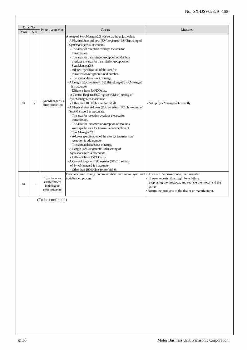
No. SX-DSV02829 -155-
Error No.
Protective function Causes Measures Maiin Sub
81 7 SyncManager2/3 error protection
A setup of SyncManager2/3 was set as the unjust value. - A Physical Start Address (ESC registersh 0810h) setting of
SyncManager2 is inaccurate. - The area for reception overlaps the area for
transmission. - The area for transmission/reception of Mailbox
overlaps the area for transmission/reception of SyncManager2/3
- Address specification of the area for transmission/reception is odd number.
- The start address is out of range. - A Length (ESC registersh 0812h) setting of SyncManager2
is inaccurate. - Different from RxPDO size.
- A Control Register:ESC register (0814h) setting of SyncManager2 is inaccurate. - Other than 100100b is set for bit5-0.
- A Physical Start Address (ESC registersh 0818h ) setting of SyncManager3 is inaccurate. - The area for reception overlaps the area for transmission.
- The area for transmission/reception of Mailbox overlaps the area for transmission/reception of SyncManager2/3
- Address specification of the area for transmission/ reception is odd number.
- The start address is out of range. - A Length (ESC register 081Ah) setting of
SyncManager3 is inaccurate. - Different from TxPDO size.
- A Control Register:ESC register (081Ch) setting of SyncManager3 is inaccurate. - Other than 100000b is set for bit5-0.
- Set up SyncManager2/3 correctly.
84 3
Synchronous establishment initialization
error protection
Error occurred during communication and servo sync and initialization process.
• Turn off the power once, then re-enter. • If error repeats, this might be a failure.
Stop using the products, and replace the motor and the driver.
• Return the products to the dealer or manufacturer.
(To be continued)
R1.00 Motor Business Unit, Panasonic Corporation
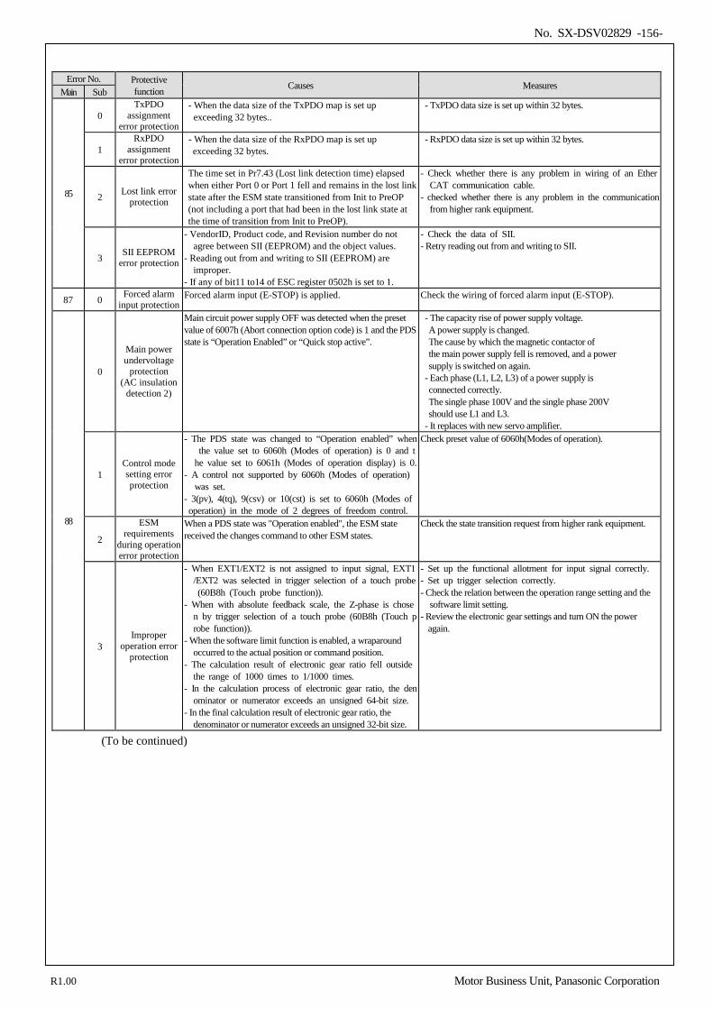
No. SX-DSV02829 -156-
Error No. Protective
function Causes Measures Main Sub
85
0 TxPDO
assignment error protection
- When the data size of the TxPDO map is set up exceeding 32 bytes..
- TxPDO data size is set up within 32 bytes.
1 RxPDO
assignment error protection
- When the data size of the RxPDO map is set up exceeding 32 bytes.
- RxPDO data size is set up within 32 bytes.
2 Lost link error protection
The time set in Pr7.43 (Lost link detection time) elapsed when either Port 0 or Port 1 fell and remains in the lost link state after the ESM state transitioned from Init to PreOP (not including a port that had been in the lost link state at the time of transition from Init to PreOP).
- Check whether there is any problem in wiring of an EtherCAT communication cable.
- checked whether there is any problem in the communication from higher rank equipment.
3 SII EEPROM error protection
- VendorID, Product code, and Revision number do not agree between SII (EEPROM) and the object values.
- Reading out from and writing to SII (EEPROM) are improper.
- If any of bit11 to14 of ESC register 0502h is set to 1.
- Check the data of SII. - Retry reading out from and writing to SII.
87 0 Forced alarm input protection
Forced alarm input (E-STOP) is applied. Check the wiring of forced alarm input (E-STOP).
88
0
Main power undervoltage
protection (AC insulation
detection 2)
Main circuit power supply OFF was detected when the preset value of 6007h (Abort connection option code) is 1 and the PDS state is “Operation Enabled” or “Quick stop active”.
- The capacity rise of power supply voltage. A power supply is changed. The cause by which the magnetic contactor of the main power supply fell is removed, and a power supply is switched on again.
- Each phase (L1, L2, L3) of a power supply is connected correctly. The single phase 100V and the single phase 200V should use L1 and L3.
- It replaces with new servo amplifier.
1 Control mode setting error protection
- The PDS state was changed to “Operation enabled” when the value set to 6060h (Modes of operation) is 0 and the value set to 6061h (Modes of operation display) is 0.
- A control not supported by 6060h (Modes of operation) was set.
- 3(pv), 4(tq), 9(csv) or 10(cst) is set to 6060h (Modes of operation) in the mode of 2 degrees of freedom control.
Check preset value of 6060h(Modes of operation).
2
ESM requirements
during operation error protection
When a PDS state was "Operation enabled", the ESM state received the changes command to other ESM states.
Check the state transition request from higher rank equipment.
3 Improper
operation error protection
- When EXT1/EXT2 is not assigned to input signal, EXT1/EXT2 was selected in trigger selection of a touch probe (60B8h (Touch probe function)).
- When with absolute feedback scale, the Z-phase is chosen by trigger selection of a touch probe (60B8h (Touch probe function)).
- When the software limit function is enabled, a wraparound occurred to the actual position or command position.
- The calculation result of electronic gear ratio fell outside the range of 1000 times to 1/1000 times.
- In the calculation process of electronic gear ratio, the denominator or numerator exceeds an unsigned 64-bit size.
- In the final calculation result of electronic gear ratio, the denominator or numerator exceeds an unsigned 32-bit size.
- Set up the functional allotment for input signal correctly. - Set up trigger selection correctly. - Check the relation between the operation range setting and the
software limit setting. - Review the electronic gear settings and turn ON the power
again.
(To be continued)
R1.00 Motor Business Unit, Panasonic Corporation
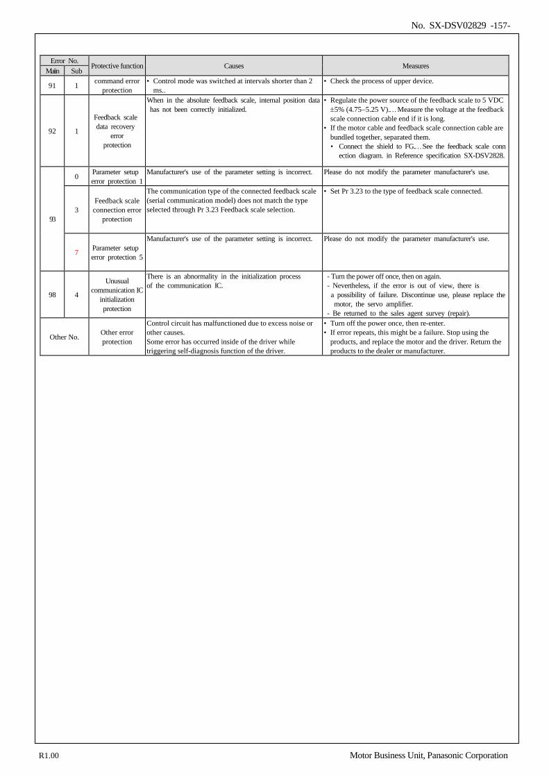
No. SX-DSV02829 -157-
Error No.
Protective function Causes Measures Maiin Sub
91 1 command error protection
• Control mode was switched at intervals shorter than 2 ms..
• Check the process of upper device.
92 1
Feedback scale data recovery
error protection
When in the absolute feedback scale, internal position data has not been correctly initialized.
• Regulate the power source of the feedback scale to 5 VDC ±5% (4.75−5.25 V).…Measure the voltage at the feedback scale connection cable end if it is long.
• If the motor cable and feedback scale connection cable are bundled together, separated them. • Connect the shield to FG.…See the feedback scale conn
ection diagram. in Reference specification SX-DSV2828.
93
0 Parameter setup error protection 1
Manufacturer's use of the parameter setting is incorrect. Please do not modify the parameter manufacturer's use.
3 Feedback scale connection error
protection
The communication type of the connected feedback scale (serial communication model) does not match the type selected through Pr 3.23 Feedback scale selection.
• Set Pr 3.23 to the type of feedback scale connected.
7 Parameter setup error protection 5
Manufacturer's use of the parameter setting is incorrect. Please do not modify the parameter manufacturer's use.
98 4
Unusual communication IC
initialization protection
There is an abnormality in the initialization process of the communication IC.
- Turn the power off once, then on again. - Nevertheless, if the error is out of view, there is
a possibility of failure. Discontinue use, please replace the motor, the servo amplifier.
- Be returned to the sales agent survey (repair).
Other No. Other error protection
Control circuit has malfunctioned due to excess noise or other causes. Some error has occurred inside of the driver while triggering self-diagnosis function of the driver.
• Turn off the power once, then re-enter. • If error repeats, this might be a failure. Stop using the
products, and replace the motor and the driver. Return the products to the dealer or manufacturer.
R1.00 Motor Business Unit, Panasonic Corporation
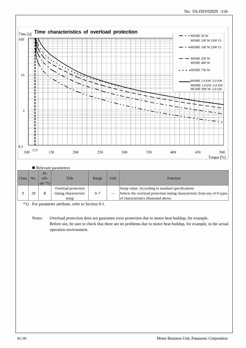
No. SX-DSV02829 -158-
Relevant parameters
Class No. At- trib-
ute *1) Title Range Unit Function
9 29 R Overload protection timing characteristic
setup 0–7 —
Setup value: According to standard specifications Selects the overload protection timing characteristic from any of 8 types of characteristics illustrated above.
*1) For parameter attribute, refer to Section 9-1.
Notes: Overload protection does not guarantee error protection due to motor heat buildup, for example.
Before use, be sure to check that there are no problems due to motor heat buildup, for example, in the actual operation environment.
MSME 50 W MSME 100 W (100 V)
MSME 100 W (200 V)
MSME 200 W MSME 400 W
MSME 750 W
MGME 900 W–3.0 kW
MSME 1.0 kW–5.0 kW MDME 1.0 kW–5.0 kW
Time characteristics of overload protection
R1.00 Motor Business Unit, Panasonic Corporation
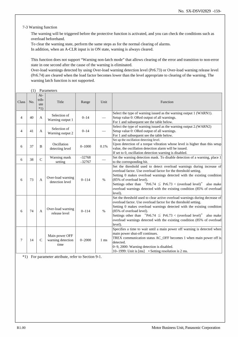
No. SX-DSV02829 -159-
7-3 Warning function
The warning will be triggered before the protective function is activated, and you can check the conditions such as overload beforehand. To clear the warning state, perform the same steps as for the normal clearing of alarms. In addition, when an A-CLR input is in ON state, warning is always cleared. This function does not support “Warning non-latch mode” that allows clearing of the error and transition to non-error state in one second after the cause of the warning is eliminated. Over-load warnings detected by using Over-load warning detection level (Pr6.73) or Over-load warning release level (Pr6.74) are cleared when the load factor becomes lower than the level appropriate to clearing of the warning. The warning latch function is not supported. (1) Parameters
Class No.
At- trib- ute *1)
Title Range Unit Function
4 40 A Selection of Warning output 1 0–14 —
Select the type of warning issued as the warning output 1 (WARN1). Setup value 0: ORed output of all warnings. For 1 and subsequent see the table below.
4 41 A Selection of Warning output 2 0–14 —
Select the type of warning issued as the warning output 2.(WARN2) Setup value 0: ORed output of all warnings. For 1 and subsequent see the table below.
6 37 B Oscillation detecting level 0–1000 0.1%
Set up the oscillation detecting level. Upon detection of a torque vibration whose level is higher than this setup value, the oscillation detection alarm will be issued. If set to 0, oscillation detection warning is disabled.
6 38 C Warning mask setting
-32768 –32767 — Set the warning detection mask. To disable detection of a warning, place 1
to the corresponding bit.
6 73 A Over-load warning detection level 0–114 %
Set the threshold used to detect overload warnings during increase of overload factor. Use overload factor for the threshold setting. Setting 0 makes overload warnings detected with the existing condition (85% of overload level). Settings other than “Pr6.74 ≦ Pr6.73 < (overload level)” also make overload warnings detected with the existing condition (85% of overload level).
6 74 A Over-load warning release level 0–114 %
Set the threshold used to clear active overload warnings during decrease of overload factor. Use overload factor for the threshold setting. Setting 0 makes overload warnings detected with the existing condition (85% of overload level). Settings other than “Pr6.74 ≦ Pr6.73 < (overload level)” also make overload warnings detected with the existing condition (85% of overload level).
7 14 C Main power OFF warning detection
time 0−2000 1 ms
Specifies a time to wait until a main power off warning is detected when main power shut-off continues. TREX communication status AC_OFF becomes 1 when main power off is detected. 0−9, 2000: Warning detection is disabled. 10−1999: Unit is [ms] • Setting resolution is 2 ms.
*1) For parameter attribute, refer to Section 9-1.
R1.00 Motor Business Unit, Panasonic Corporation
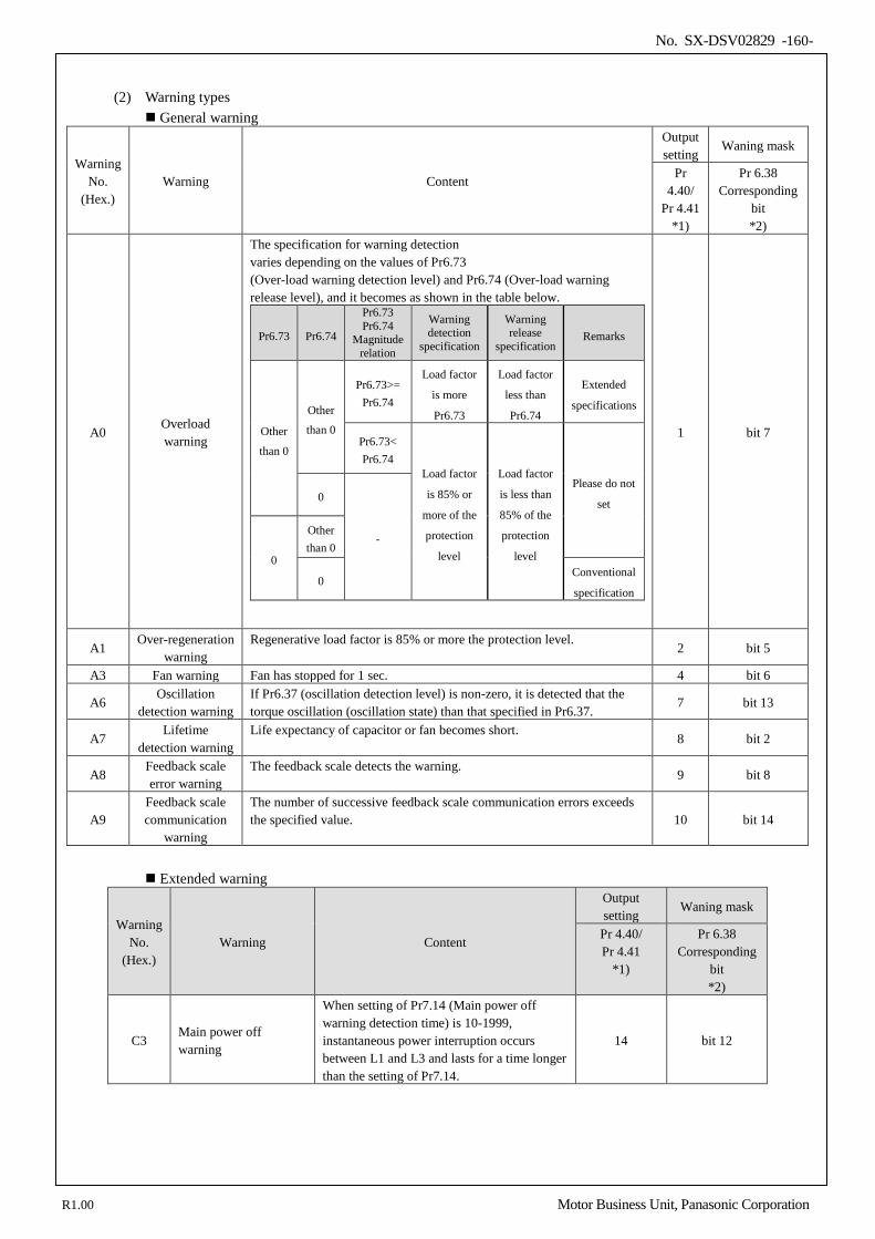
No. SX-DSV02829 -160-
(2) Warning types
General warning
Warning No.
(Hex.) Warning Content
Output setting
Waning mask
Pr 4.40/
Pr 4.41 *1)
Pr 6.38 Corresponding
bit *2)
A0 Overload warning
The specification for warning detection varies depending on the values of Pr6.73 (Over-load warning detection level) and Pr6.74 (Over-load warning release level), and it becomes as shown in the table below.
Pr6.73 Pr6.74
Pr6.73 Pr6.74
Magnitude relation
Warning detection
specification
Warning release
specification Remarks
Other
than 0
Other
than 0
Pr6.73>= Pr6.74
Load factor
is more
Pr6.73
Load factor
less than
Pr6.74
Extended
specifications
Pr6.73< Pr6.74
Load factor
is 85% or
more of the
protection
level
Load factor
is less than
85% of the
protection
level
Please do not
set 0
-
0
Other than 0
0 Conventional
specification
1 bit 7
A1 Over-regeneration
warning Regenerative load factor is 85% or more the protection level.
2 bit 5
A3 Fan warning Fan has stopped for 1 sec. 4 bit 6
A6 Oscillation
detection warning If Pr6.37 (oscillation detection level) is non-zero, it is detected that the torque oscillation (oscillation state) than that specified in Pr6.37.
7 bit 13
A7 Lifetime
detection warning Life expectancy of capacitor or fan becomes short.
8 bit 2
A8 Feedback scale error warning
The feedback scale detects the warning. 9 bit 8
A9 Feedback scale communication
warning
The number of successive feedback scale communication errors exceeds the specified value. 10 bit 14
Extended warning
Warning No.
(Hex.) Warning Content
Output setting
Waning mask
Pr 4.40/ Pr 4.41
*1)
Pr 6.38 Corresponding
bit *2)
C3 Main power off warning
When setting of Pr7.14 (Main power off warning detection time) is 10-1999, instantaneous power interruption occurs between L1 and L3 and lasts for a time longer than the setting of Pr7.14.
14 bit 12
R1.00 Motor Business Unit, Panasonic Corporation
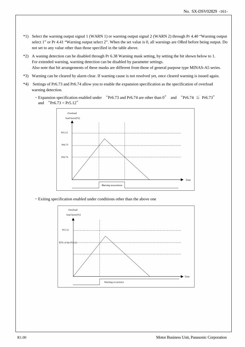
No. SX-DSV02829 -161-
*1) Select the warning output signal 1 (WARN 1) or warning output signal 2 (WARN 2) through Pr 4.40 “Warning output select 1” or Pr 4.41 “Warning output select 2”. When the set value is 0, all warnings are ORed before being output. Do not set to any value other than those specified in the table above.
*2) A waning detection can be disabled through Pr 6.38 Warning mask setting, by setting the bit shown below to 1. For extended warning, warning detection can be disabled by parameter settings. Also note that bit arrangements of these masks are different from those of general purpose type MINAS-A5 series.
*3) Warning can be cleared by alarm clear. If warning cause is not resolved yet, once cleared warning is issued again.
*4) Settings of Pr6.73 and Pr6.74 allow you to enable the expansion specification as the specification of overload warning detection.
・Expansion specification enabled under “Pr6.73 and Pr6.74 are other than 0” and “Pr6.74 ≦ Pr6.73” and “Pr6.73 < Pr5.12”
・Exiting specification enabled under conditions other than the above one
Overload
load factor[%]
Time
Warning occurrence
Pr6.74
Pr6.73
Pr5.12
Overload
load factor[%]
Time
Warning occurrence
85% of the Pr5.12
Pr5.12
R1.00 Motor Business Unit, Panasonic Corporation
No. SX-DSV02829 -162-
7-4 Setup of gain pre-adjustment protection
Before starting gain adjustment, set the following parameters based on the conditions of use, to assure safe operation.
1) Setup of over-travel inhibit input By inputting the limit sensor signal to the driver, the bumping against mechanical end can be prevented. Refer to interface specification, positive/negative direction overtravel inhibit input (POT/NOT). Set the following parameters which are related to overtravel inhibit input. Pr 5.04 Setup of over-travel inhibit input Pr 5.05 Sequence at over-travel inhibit
2) Setup of torque limit
By limiting motor maximum torque, damage caused by failure or disturbance such as bite of the machine and collision will be minimized. To uniformly limit maximum torque by using the parameter Pr 0.13 1st torque limit, first set Pr 5.21 Selection of torque limit to 0 or 1. If the torque limit setup is lower than the value required during the actual application, the following two protective features will be triggered: over-speed protection when overshoot occurs, and excess positional deviation protection when response to the command delays. By allocating the torque in-limit output (TLC) of interface specification to the output signal, torque limit condition can be detected externally.
3) Setup of over-speed protection
Generates Err 26.0 Over-speed protection when the motor speed is excessively high. If your application operates below the motor maximum speed, set Pr 9.10 “Maximum over-speed level” by using the formula below.
Pr 9.10 “Maximum over-speed level”= Vmax × (1.2 to 1.5) Vmax: motor maximum speed [r/min] in operating condition Factor in ( ) is margin to prevent frequent activation of over-speed protection.
When running the motor at a low speed during initial adjustment stage, setup the overspeed protection by multiplying the adjusting speed by a certain margin to protect the motor against possible oscillation.
R1.00 Motor Business Unit, Panasonic Corporation
No. SX-DSV02829 -163-
4) Setup of the excess positional deviation protection
During the position control, this function detects potential excessive difference between the positional command and motor position and issues Err 24.0 Excess positional deviation protection. Excessive position deviation level can be set in Pr0.14" Position deviation excess setup ". (See the control block diagram.) Because the positional deviation during normal operation depends on the operating speed and gain setting, fill the equation below based on your operating condition and input the resulting value to Pr 0.14.
Pr0.14" Position deviation excess setup " = Ve / Kp * (1.2 - 2.0)
Ve:The maximum operating frequency of the Feedback scale unit or external scale units [pulse/s] Kp:Position loop gain [1/s] Coefficients in parentheses are margins of protection to prevent frequent excessive position deviation.
Notes: • When switching position loop gain Kp, select the smallest value for calculation. • When switching from the velocity control to position control, position deviation correcting function is used,
which will increase calculation value and error. To cope with these problems, increase the margin.
5) Setup of motor working range During the position control, this function detects the motor position which exceeds the amount of travel set to Pr 5.14 Motor working range setup, and issues Err 34.0 Software limit protection. For details, refer to 6-2 Motor working range setup function.
R1.00 Motor Business Unit, Panasonic Corporation
No. SX-DSV02829 -164-
8.Safety function
8-1 Outline description of safe torque off (STO) ..................................................................................................... 165 8-2 Specifications of Input & output signals ........................................................................................................... 166 8-2-1 Safety input/ signal....................................................................................................................................... 166 8-2-2 External device monitor (EDM) output signal ............................................................................................. 167 8-2-3 Internal signal circuit block diagram ............................................................................................................ 167
8-3 Detailed functional description.......................................................................................................................... 168 8-3-1 Operating timing for safety status ................................................................................................................ 168 8-3-2 Return timing from safety state .................................................................................................................... 169
8-4 Example of connection ...................................................................................................................................... 170 8-4-1 Example of connection to safety switch ....................................................................................................... 170 8-4-2 Example of connection to safety sensor ....................................................................................................... 170 8-4-3 Example of connection to safety controller .................................................................................................. 171 8-4-4 Example of connection when using multiple axes ....................................................................................... 172
8-5 Safety precautions ............................................................................................................................................. 173
When the last two digits of the part number are alphabetical characters or the second last digit is an alphabetical character and the last digit is numeric(*Excluding C1 to C9), the servo driver can’t be used due to no safety function incorporated. This chapter is a description of the part number with safety functions. (When the last two digits of the part number are numeric, the second last digit is numeric and the last digit is an alphabetical character, or the last two digits are C1 to C9)
For details such as circuit constants in this chapter, refer to the reference specification (SX-DSV02828).
8
R1.00 Motor Business Unit, Panasonic Corporation
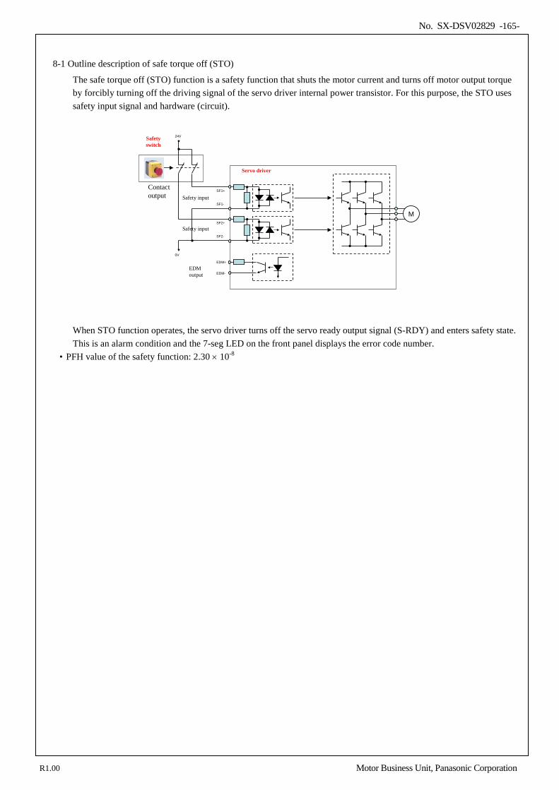
No. SX-DSV02829 -165-
8-1 Outline description of safe torque off (STO)
The safe torque off (STO) function is a safety function that shuts the motor current and turns off motor output torque by forcibly turning off the driving signal of the servo driver internal power transistor. For this purpose, the STO uses safety input signal and hardware (circuit).
Safety input
EDM output
Servo driver
Contact output
0V
24V
SF1+
SF2+
SF2-
EDM+
EDM-
Safety switch
MSF1-
Safety input
When STO function operates, the servo driver turns off the servo ready output signal (S-RDY) and enters safety state. This is an alarm condition and the 7-seg LED on the front panel displays the error code number.
• PFH value of the safety function: 2.30 × 10⁻⁸
R1.00 Motor Business Unit, Panasonic Corporation
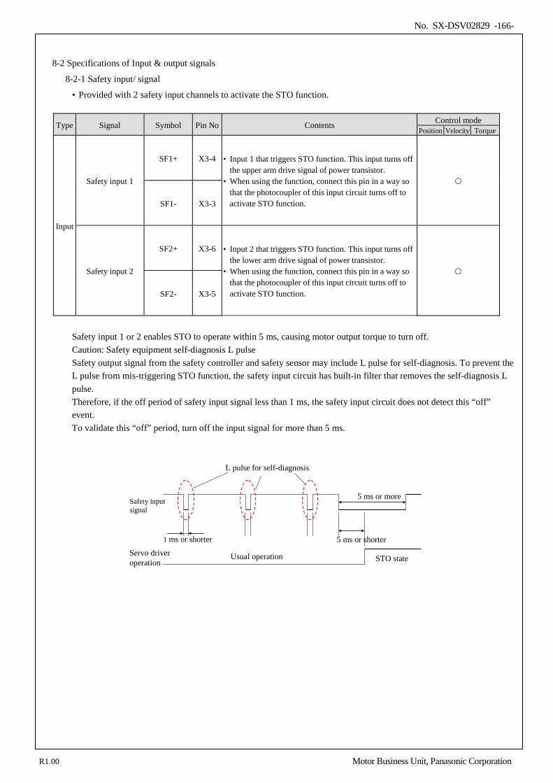
No. SX-DSV02829 -166-
8-2 Specifications of Input & output signals
8-2-1 Safety input/ signal
• Provided with 2 safety input channels to activate the STO function.
Type Signal Symbol Pin No Contents Control mode Position Velocity Torque
Input
Safety input 1
SF1+ X3-4 • Input 1 that triggers STO function. This input turns off the upper arm drive signal of power transistor.
• When using the function, connect this pin in a way so that the photocoupler of this input circuit turns off to activate STO function.
SF1- X3-3
Safety input 2
SF2+ X3-6 • Input 2 that triggers STO function. This input turns off the lower arm drive signal of power transistor.
• When using the function, connect this pin in a way so that the photocoupler of this input circuit turns off to activate STO function.
SF2- X3-5
Safety input 1 or 2 enables STO to operate within 5 ms, causing motor output torque to turn off. Caution: Safety equipment self-diagnosis L pulse Safety output signal from the safety controller and safety sensor may include L pulse for self-diagnosis. To prevent the L pulse from mis-triggering STO function, the safety input circuit has built-in filter that removes the self-diagnosis L pulse. Therefore, if the off period of safety input signal less than 1 ms, the safety input circuit does not detect this “off” event. To validate this “off” period, turn off the input signal for more than 5 ms.
L pulse for self-diagnosis
1 ms or shorter 5 ms or shorter
Usual operation STO state
Safety input signal
Servo driveroperation
5 ms or more
R1.00 Motor Business Unit, Panasonic Corporation
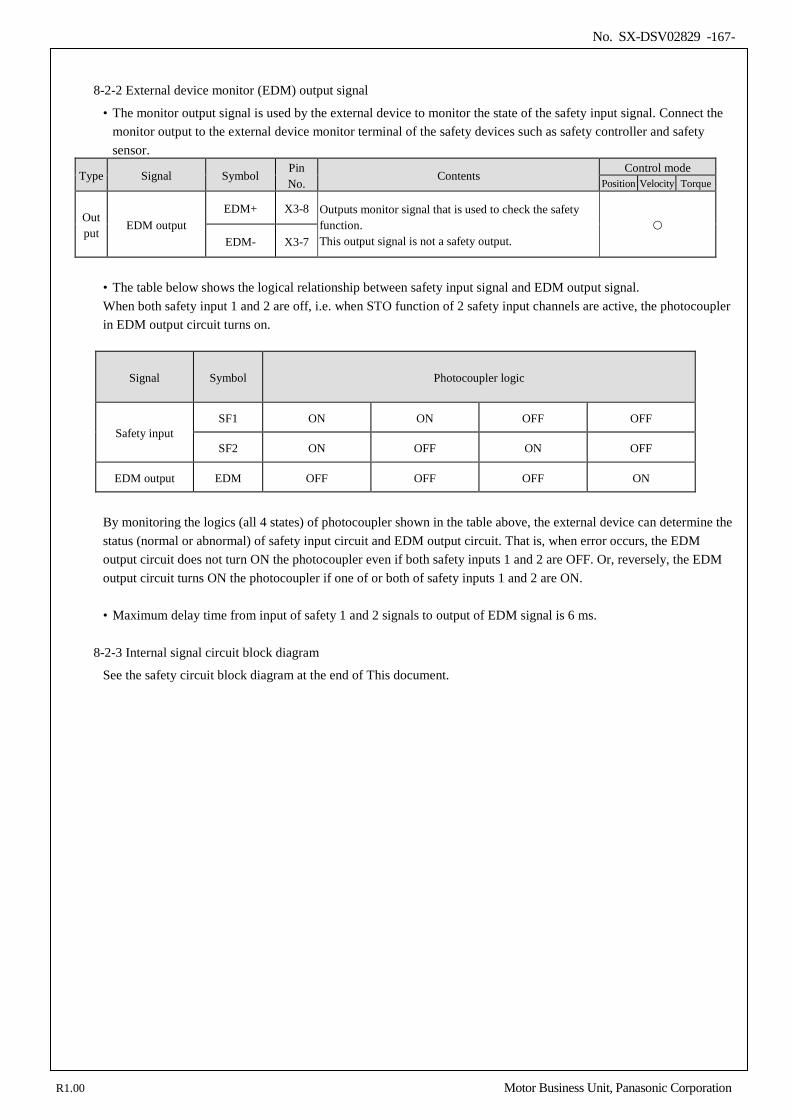
No. SX-DSV02829 -167-
8-2-2 External device monitor (EDM) output signal
• The monitor output signal is used by the external device to monitor the state of the safety input signal. Connect the monitor output to the external device monitor terminal of the safety devices such as safety controller and safety sensor.
Type Signal Symbol Pin No.
Contents Control mode
Position Velocity Torque
Out put
EDM output EDM+ X3-8 Outputs monitor signal that is used to check the safety
function. This output signal is not a safety output.
EDM- X3-7
• The table below shows the logical relationship between safety input signal and EDM output signal. When both safety input 1 and 2 are off, i.e. when STO function of 2 safety input channels are active, the photocoupler in EDM output circuit turns on.
Signal Symbol Photocoupler logic
Safety input SF1 ON ON OFF OFF
SF2 ON OFF ON OFF
EDM output EDM OFF OFF OFF ON
By monitoring the logics (all 4 states) of photocoupler shown in the table above, the external device can determine the status (normal or abnormal) of safety input circuit and EDM output circuit. That is, when error occurs, the EDM output circuit does not turn ON the photocoupler even if both safety inputs 1 and 2 are OFF. Or, reversely, the EDM output circuit turns ON the photocoupler if one of or both of safety inputs 1 and 2 are ON.
• Maximum delay time from input of safety 1 and 2 signals to output of EDM signal is 6 ms.
8-2-3 Internal signal circuit block diagram
See the safety circuit block diagram at the end of This document.
R1.00 Motor Business Unit, Panasonic Corporation
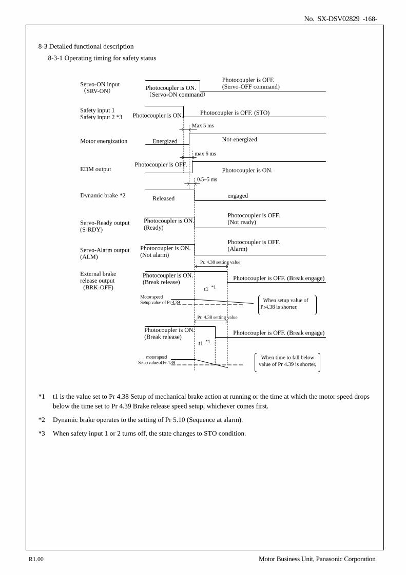
No. SX-DSV02829 -168-
8-3 Detailed functional description
8-3-1 Operating timing for safety status
Photocoupler is ON.
engaged
Photocoupler is ON. (Break release)
Released
Motor speed Setup value of Pr 4.39
Pr. 4.38 setting value
t1 *1
motor speed Setup value of Pr 4.39
When setup value of Pr4.38 is shorter,
When time to fall below value of Pr 4.39 is shorter,
Photocoupler is ON. (Ready)
Photocoupler is ON. (Not alarm)
Pr. 4.38 setting value
t1 *1
Photocoupler is OFF. (Not ready)
Photocoupler is OFF. (Alarm)
Photocoupler is OFF. (Break engage)
Photocoupler is ON. (Break release) Photocoupler is OFF. (Break engage)
Photocoupler is OFF. (STO) Safety input 1 Safety input 2 *3
Not-energized Energized
Max 5 ms
Motor energization
Dynamic brake *2
External brake release output (BRK-OFF)
Servo-Ready output (S-RDY)
Servo-Alarm output (ALM)
Servo-ON input (SRV-ON) Photocoupler is ON.
(Servo-ON command)
Photocoupler is OFF. (Servo-OFF command)
Photocoupler is ON. Photocoupler is OFF.
max 6 ms
EDM output 0.5–5 ms
*1 t1 is the value set to Pr 4.38 Setup of mechanical brake action at running or the time at which the motor speed drops
below the time set to Pr 4.39 Brake release speed setup, whichever comes first.
*2 Dynamic brake operates to the setting of Pr 5.10 (Sequence at alarm).
*3 When safety input 1 or 2 turns off, the state changes to STO condition.
R1.00 Motor Business Unit, Panasonic Corporation
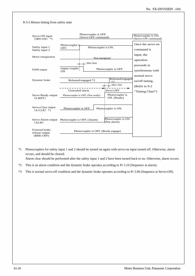
No. SX-DSV02829 -169-
8-3-2 Return timing from safety state
Photocoupler is OFF. Photocoupler is ON.
Photocoupler is OFF. (Servo-OFF command)
Once the servo on
command is
input, the
operation
proceeds in
synchronous with
normal servo
on/off timing.
(Refer to 9-2
“Timing Chart”)
Not-energized Max 6ms
Photocoupler is ON. (Ready)
Photocoupler is OFF. (Alarm)
Photocoupler is OFF. (Not ready)
Photocoupler is OFF. (Break engage)
Photocoupler is OFF. Photocoupler is ON.
Photocoupler is ON. (Not alarm)
Released/engaged *2
Servo-OFF
Released/engaged *3
Generated alarm
Safety input 1 Safety input 2
Servo-ON input (SRV-ON)*1
External brake release output
(BRK-OFF)
Motor energization
Servo-Ready output (S-RDY)
Servo-Alarm output(ALM)
Servo-Clear intput(A-CLR)*1
Dynamic brake
EDM output output coupler ON
Photocoupler is OFF.
Photocoupler is ON. (Servo-ON command)
Max 2ms
*1 Photocouplers for safety input 1 and 2 should be turned on again with servo-on input turned off. Otherwise, alarm occurs, and should be cleared. Alarm clear should be performed after the safety input 1 and 2 have been turned back to on. Otherwise, alarm occurs.
*2 This is an alarm condition and the dynamic brake operates according to Pr 5.10 (Sequence at alarm).
*3 This is normal servo-off condition and the dynamic brake operates according to Pr 5.06 (Sequence at Servo-Off).
R1.00 Motor Business Unit, Panasonic Corporation
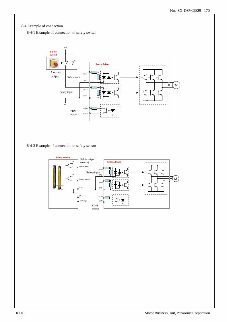
No. SX-DSV02829 -170-
8-4 Example of connection
8-4-1 Example of connection to safety switch
Safety input
EDM output
Servo driver
Contact output
0V
24V
SF1+
SF2+
SF2-
EDM+
EDM-
Safety switch
MSF1-
Safety input
8-4-2 Example of connection to safety sensor
EDM output
Servo driver
SF1+
SF2+
SF2-
EDM+
EDM-
MSF1-
Safety output(source)
Safety sensor
Control output 1
Control output 2
0 V
24 V
EDM input
Safety input
R1.00 Motor Business Unit, Panasonic Corporation
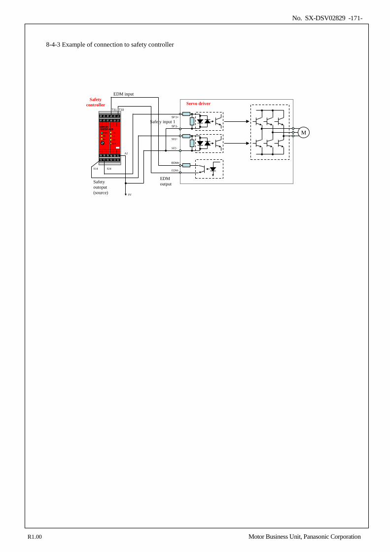
No. SX-DSV02829 -171-
8-4-3 Example of connection to safety controller
EDM output
Servo driver
SF1+
SF2+
SF2-
EDM+
EDM-
MSF1-
PWR
ERR
G9SX-AD
EIT2
ED
T1FB
S14 S24
T31 T33
Safety outoput(source) 0V
A2
EDM inputSafety
controller
Safety input 1
R1.00 Motor Business Unit, Panasonic Corporation
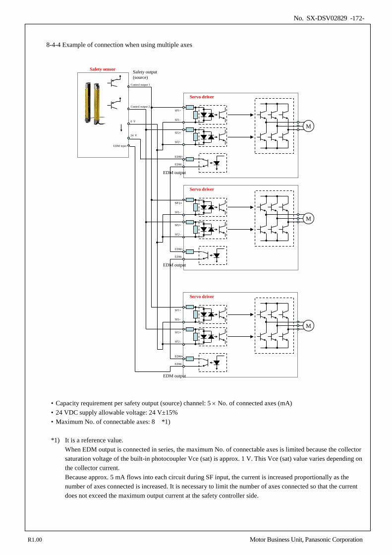
No. SX-DSV02829 -172-
8-4-4 Example of connection when using multiple axes
EDM output
Servo driver
SF1+
SF2+
SF2-
EDM+
EDM-
MSF1-
Safety output(source)
Safety sensor
Control output 1
Control output 2
0 V
24 V
EDM input
EDM output
Servo driver
SF1+
SF2+
SF2-
EDM+
EDM-
MSF1-
EDM output
Servo driver
SF1+
SF2+
SF2-
EDM+
EDM-
MSF1-
• Capacity requirement per safety output (source) channel: 5 × No. of connected axes (mA) • 24 VDC supply allowable voltage: 24 V±15% • Maximum No. of connectable axes: 8 *1)
*1) It is a reference value.
When EDM output is connected in series, the maximum No. of connectable axes is limited because the collector saturation voltage of the built-in photocoupler Vce (sat) is approx. 1 V. This Vce (sat) value varies depending on the collector current. Because approx. 5 mA flows into each circuit during SF input, the current is increased proportionally as the number of axes connected is increased. It is necessary to limit the number of axes connected so that the current does not exceed the maximum output current at the safety controller side.
R1.00 Motor Business Unit, Panasonic Corporation
No. SX-DSV02829 -173-
8-5 Safety precautions
When using the STO function, be sure to perform equipment risk assessment to ensure that the system conforms to the safety requirements.
Even while the STO function is working, the following potential safety hazards exist. Check safety in risk
assessment. • The motor may move when eternal force (e.g. gravity force on vertical axis) is exerted on it. Provide an external
brake, etc., as necessary to secure the motor. Note that the purpose of motor with brake is holding and it cannot be used for braking application.
• When parameter 605Eh(Fault reaction option code) is set to free run (disable dynamic brake), the motor is free run state and requires longer stop distance even if no external force is applied. Make sure that this does not cause any problem.
• When power transistor, etc., becomes defective, the motor will move to the extent equivalent of 180 electrical angle (max.). Make sure that this does not cause any problem.
• The STO turns off the current to the motor but does not turn off power to the servo driver and does not isolate it. When starting maintenance service on the servo driver, turn off the driver by using a different disconnecting device.
External device monitor (hereafter EDM) output signal is not a safety signal. Do not use it for an application other
than failure monitoring.
Dynamic brake and external brake release signal output are not related to safety function. When designing the system, make sure that the failure of external brake release during STO condition does not result in danger condition.
When using STO function, connect equipment conforming to the safety standards.
R1.00 Motor Business Unit, Panasonic Corporation
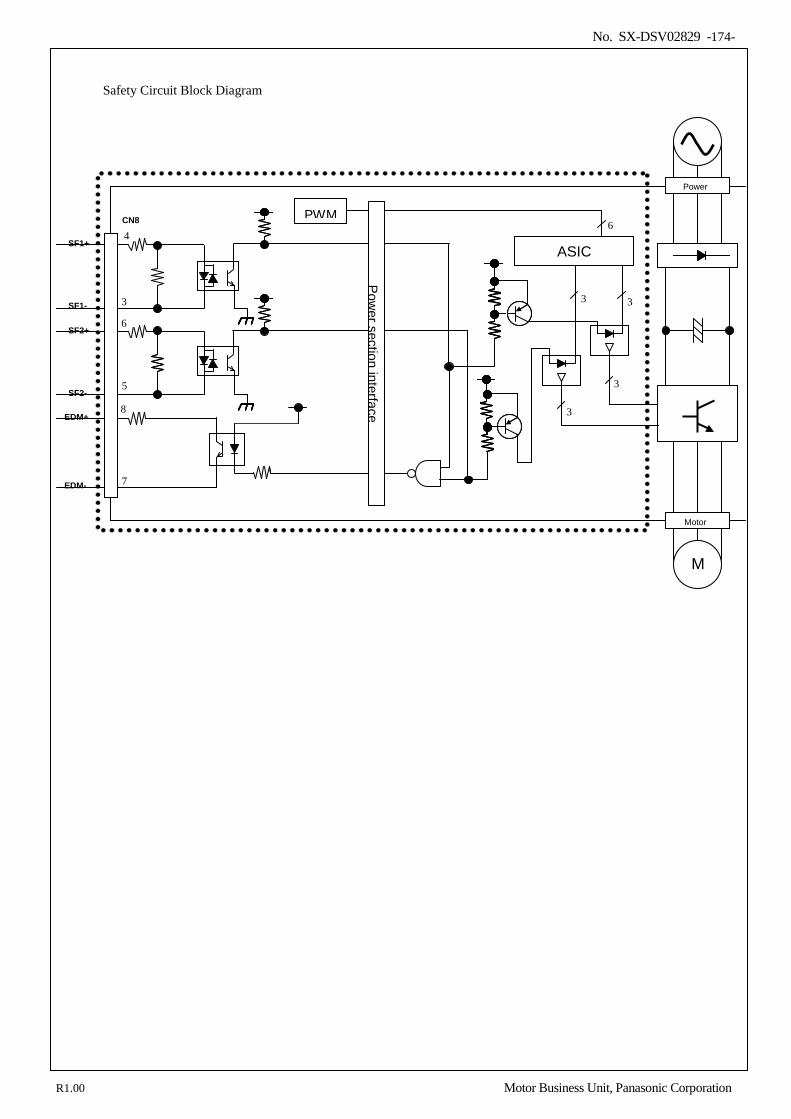
No. SX-DSV02829 -174-
Safety Circuit Block Diagram
Motor
M
Power
ASIC
EDM-
EDM+ SF2-
SF2+
SF1+
SF1- 3 6
5 8
7
4 6
3
3
3
3
PWM CN8 4 CN8
3
6
5
8
7
6
3 3
3
3
Power section interface
R1.00 Motor Business Unit, Panasonic Corporation
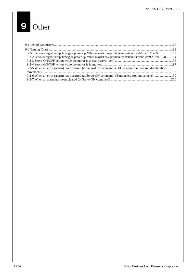
No. SX-DSV02829 -175-
9.Other
9-1 List of parameters .............................................................................................................................................. 176 9-2 Timing Chart ..................................................................................................................................................... 192 9-2-1 Servo-on signal accept timing on power-up: When magnet pole position estimation is valid (Pr 9.20 = 2) ................ 192 9-2-2 Servo-on signal accept timing on power-up: When magnet pole position estimation is invalid (Pr 9.20 = 0, 1, 3) ...... 194 9-2-3 Servo-ON/OFF action while the motor is at stall (servo-lock) .................................................................... 196 9-2-4 Servo-ON/OFF action while the motor is in motion .................................................................................... 197 9-2-5 When an error (alarm) has occurred (at Servo-ON command) (DB deceleration,Free run deceleration movement) ............................................................................................................................................................. 198 9-2-6 When an error (alarm) has occurred (at Servo-ON command) (Emergency stop movement) ..................... 199 9-2-7 When an alarm has been cleared (at Servo-ON command) ......................................................................... 200
9
R1.00 Motor Business Unit, Panasonic Corporation
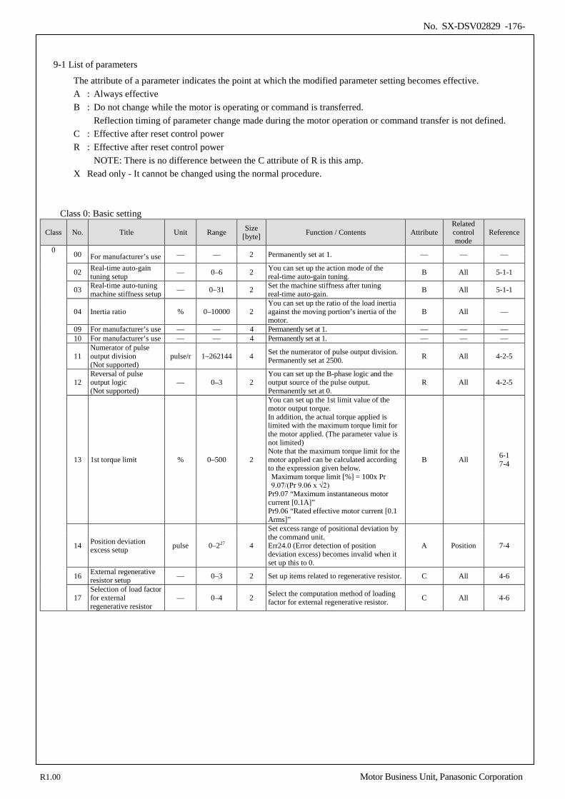
No. SX-DSV02829 -176-
9-1 List of parameters
The attribute of a parameter indicates the point at which the modified parameter setting becomes effective. A : Always effective B : Do not change while the motor is operating or command is transferred. Reflection timing of parameter change made during the motor operation or command transfer is not defined. C : Effective after reset control power R : Effective after reset control power
NOTE: There is no difference between the C attribute of R is this amp. X Read only - It cannot be changed using the normal procedure.
Class 0: Basic setting
Class No. Title Unit Range Size [byte] Function / Contents Attribute
Related control mode
Reference
0 00 For manufacturer’s use — — 2 Permanently set at 1. — — —
02 Real-time auto-gain tuning setup — 0–6 2 You can set up the action mode of the
real-time auto-gain tuning. B All 5-1-1
03 Real-time auto-tuning machine stiffness setup — 0–31 2 Set the machine stiffness after tuning
real-time auto-gain. B All 5-1-1
04 Inertia ratio % 0–10000 2
You can set up the ratio of the load inertia against the moving portion’s inertia of the motor.
B All —
09 For manufacturer’s use — — 4 Permanently set at 1. — — — 10 For manufacturer’s use — — 4 Permanently set at 1. — — —
11 Numerator of pulse output division (Not supported)
pulse/r 1–262144 4 Set the numerator of pulse output division. Permanently set at 2500. R All 4-2-5
12 Reversal of pulse output logic (Not supported)
— 0–3 2 You can set up the B-phase logic and the output source of the pulse output. Permanently set at 0.
R All 4-2-5
13 1st torque limit % 0–500 2
You can set up the 1st limit value of the motor output torque. In addition, the actual torque applied is limited with the maximum torque limit for the motor applied. (The parameter value is not limited) Note that the maximum torque limit for the motor applied can be calculated according to the expression given below. Maximum torque limit [%] = 100x Pr 9.07/(Pr 9.06 x √2)
Pr9.07 “Maximum instantaneous motor current [0.1A]” Pr9.06 “Rated effective motor current [0.1 Arms]”
B All 6-1 7-4
14 Position deviation excess setup pulse 0–227 4
Set excess range of positional deviation by the command unit. Err24.0 (Error detection of position deviation excess) becomes invalid when it set up this to 0.
A Position 7-4
16 External regenerative resistor setup — 0–3 2 Set up items related to regenerative resistor. C All 4-6
17 Selection of load factor for external regenerative resistor
— 0–4 2 Select the computation method of loading factor for external regenerative resistor. C All 4-6
R1.00 Motor Business Unit, Panasonic Corporation
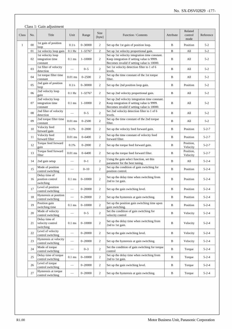
No. SX-DSV02829 -177-
Class 1: Gain adjustment
Class No. Title Unit Range Size [byte] Function / Contents Attribute
Related control mode
Reference
1 00 1st gain of position loop 0.1/s 0–30000 2 Set up the 1st gain of position loop. B Position 5-2
01 1st velocity loop gain 0.1 Hz 1–32767 2 Set up 1st velocity proportional gain. B All 5-2
02 1st velocity loop integration time constant
0.1 ms 1–10000 2 Set up 1st velocity integration time constant. Keep integration if setting value is 9999. Becomes invalid if setting value is 10000.
B All 5-2
03 1st filter of velocity detection — 0–5 2 Set 1st velocity detection filter to 1 of 6
levels. B All 5-2
04 1st torque filter time constant 0.01 ms 0–2500 2 Set up the time constant of the 1st torque
filter. B All 5-2
05 2nd gain of position loop 0.1/s 0–30000 2 Set up the 2nd position loop gain. B Position 5-2
06 2nd velocity loop gain 0.1 Hz 1–32767 2 Set up 2nd velocity proportional gain. B All 5-2
07 2nd velocity loop integration time constant
0.1 ms 1–10000 2 Set up 2nd velocity integration time constant. Keep integration if setting value is 9999. Becomes invalid if setting value is 10000.
B All 5-2
08 2nd filter of velocity detection — 0–5 2 Set 2nd velocity detection filter to 1 of 6
levels. B All 5-2
09 2nd torque filter time constant 0.01 ms 0–2500 2 Set up the time constant of the 2nd torque
filter. B All 5-2
10 Velocity feed forward gain 0.1% 0–2000 2 Set up the velocity feed forward gain. B Position 5-2-7
11 Velocity feed forward filter 0.01 ms 0–6400 2 Set up the time constant of velocity feed
forward filter. B Position 5-2-7
12 Torque feed forward gain 0.1% 0–2000 2 Set up the torque feed forward gain. B Position,
Velocity 5-2-7
13 Torque feed forward filter 0.01 ms 0–6400 2 Set up the torque feed forward filter. B Position,
Velocity 5-2-7
14 2nd gain setup — 0–1 2 Using the gain select function, set this parameter for the best tuning. B All 5-2-4
15 Mode of position control switching
— 0–10 2 Set up the condition of gain switching for position control. B Position 5-2-4
16 Delay time of position control switching
0.1 ms 0–10000 2 Set up the delay time when switching from 2nd to 1st gain. B Position 5-2-4
17 Level of position control switching
— 0–20000 2 Set up the gain switching level. B Position 5-2-4
18 Hysteresis at position control switching
— 0–20000 2 Set up the hysteresis at gain switching. B Position 5-2-4
19 Position gain switching time 0.1 ms 0–10000 2 Set up the position gain switching time upon
gain switching. B Position 5-2-4
20 Mode of velocity control switching — 0–5 2 Set the condition of gain switching for
velocity control B Velocity 5-2-4
21 Delay time of velocity control switching
0.1 ms 0–10000 2 Set up the delay time when switching from 2nd to 1st gain. B Velocity 5-2-4
22 Level of velocity control switching
— 0–20000 2 Set up the gain switching level. B Velocity 5-2-4
23 Hysteresis at velocity control switching
— 0–20000 2 Set up the hysteresis at gain switching. B Velocity 5-2-4
24 Mode of torque control switching
— 0–3 2 Set the condition of gain switching for torque control B Torque 5-2-4
25 Delay time of torque control switching 0.1 ms 0–10000 2 Set up the delay time when switching from
2nd to 1st gain. B Torque 5-2-4
26 Level of torque control switching
— 0–20000 2 Set up the gain switching level. B Torque 5-2-4
27 Hysteresis at torque control switching
— 0–20000 2 Set up the hysteresis at gain switching. B Torque 5-2-4
R1.00 Motor Business Unit, Panasonic Corporation
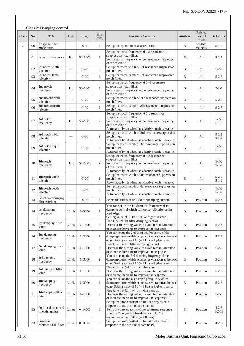
No. SX-DSV02829 -178-
Class 2: Damping control
Class No. Title Unit Range Size [byte] Function / Contents Attribute
Related control mode
Reference
2 00 Adaptive filter mode setup — 0–4 2 Set up the operation of adaptive filter. B Position,
Velocity 5-1-2
01 1st notch frequency Hz 50–5000 2
Set up the notch frequency of 1st resonance suppression notch filter. Set the notch frequency to the resonance frequency of the machine.
B All 5-2-5
02 1st notch width selection — 0–20 2 Set up the notch width of 1st resonance suppression
notch filter. B All 5-2-5
03 1st notch depth selection — 0–99 2 Set up the notch depth of 1st resonance suppression
notch filter. B All 5-2-5
04 2nd notch frequency Hz 50–5000 2
Set up the notch frequency of 2nd resonance suppression notch filter. Set the notch frequency to the resonance frequency of the machine.
B All 5-2-5
05 2nd notch width selection — 0–20 2 Set up the notch width of 2nd resonance suppression
notch filter. B All 5-2-5
06 2nd notch depth selection — 0–99 2 Set up the notch depth of 2nd resonance suppression
notch filter. B All 5-2-5
07 3rd notch frequency Hz 50–5000 2
Set up the notch frequency of 3rd resonance suppression notch filter. Set the notch frequency to the resonance frequency of the machine. Automatically set when the adaptive notch is enabled.
B All 5-2-5 5-1-2
08 3rd notch width selection — 0–20 2
Set up the notch width of 3rd resonance suppression notch filter. Automatically set when the adaptive notch is enabled.
B All 5-2-5 5-1-2
09 3rd notch depth selection — 0–99 2
Set up the notch depth of 3rd resonance suppression notch filter. Automatically set when the adaptive notch is enabled.
B All 5-2-5 5-1-2
10 4th notch frequency Hz 50–5000 2
Set up the notch frequency of 4th resonance suppression notch filter. Set the notch frequency to the resonance frequency of the machine. Automatically set when the adaptive notch is enabled.
B All 5-2-5 5-1-2
11 4th notch width selection — 0–20 2
Set up the notch width of 4th resonance suppression notch filter. Automatically set when the adaptive notch is enabled.
B All 5-2-5 5-1-2
12 4th notch depth selection — 0–99 2
Set up the notch depth of 4th resonance suppression notch filter. Automatically set when the adaptive notch is enabled.
B All 5-2-5 5-1-2
13 Selection of damping filter switching — 0–3 2 Select the filters to be used for damping control. B Position 5-2-6
14 1st damping frequency 0.1 Hz 0–3000 2
You can set up the 1st damping frequency of the damping control which suppresses vibration at the load edge. Setting value of 10 (= 1 Hz) or higher is valid.
B Position 5-2-6
15 1st damping filter setup 0.1 Hz 0–1500 2
Fine tune the 1st filter damping control. Decrease the setting value to avoid torque saturation or increase the value to improve the response.
B Position 5-2-6
16 2nd damping frequency 0.1 Hz 0–3000 2
You can set up the 2nd damping frequency of the damping control which suppresses vibration at the load edge. Setting value of 10 (= 1 Hz) or higher is valid.
B Position 5-2-6
17 2nd damping filter setup 0.1 Hz 0–1500 2
Fine tune the 2nd filter damping control. Decrease the setting value to avoid torque saturation or increase the value to improve the response.
B Position 5-2-6
18 3rd damping frequency 0.1 Hz 0–3000 2
You can set up the 3rd damping frequency of the damping control which suppresses vibration at the load edge. Setting value of 10 (= 1 Hz) or higher is valid.
B Position 5-2-6
19 3rd damping filter setup 0.1 Hz 0–1500 2
Fine tune the 3rd filter damping control. Decrease the setting value to avoid torque saturation or increase the value to improve the response.
B Position 5-2-6
20 4th damping frequency 0.1 Hz 0–3000 2
You can set up the 4th damping frequency of the damping control which suppresses vibration at the load edge. Setting value of 10 (= 1 Hz) or higher is valid.
B Position 5-2-6
21 4th damping filter setup 0.1 Hz 0–1500 2
Fine tune the 4th filter damping control. Decrease the setting value to avoid torque saturation or increase the value to improve the response.
B Position 5-2-6
22 Positional command smoothing filter 0.1 ms 0–10000 2
Set up the time constant of the 1st delay filter in response to the positional instuction. Set to the time constant of the command response filter for 2 degrees of freedom control. The maximum value is 2000 (=200.0ms).
B Position 4-2-3 5-2-13
23 Positional command FIR filter 0.1 ms 0–10000 2 Set up the time constant of the 1st delay filter in
response to the positional command. B Position 4-2-3
R1.00 Motor Business Unit, Panasonic Corporation
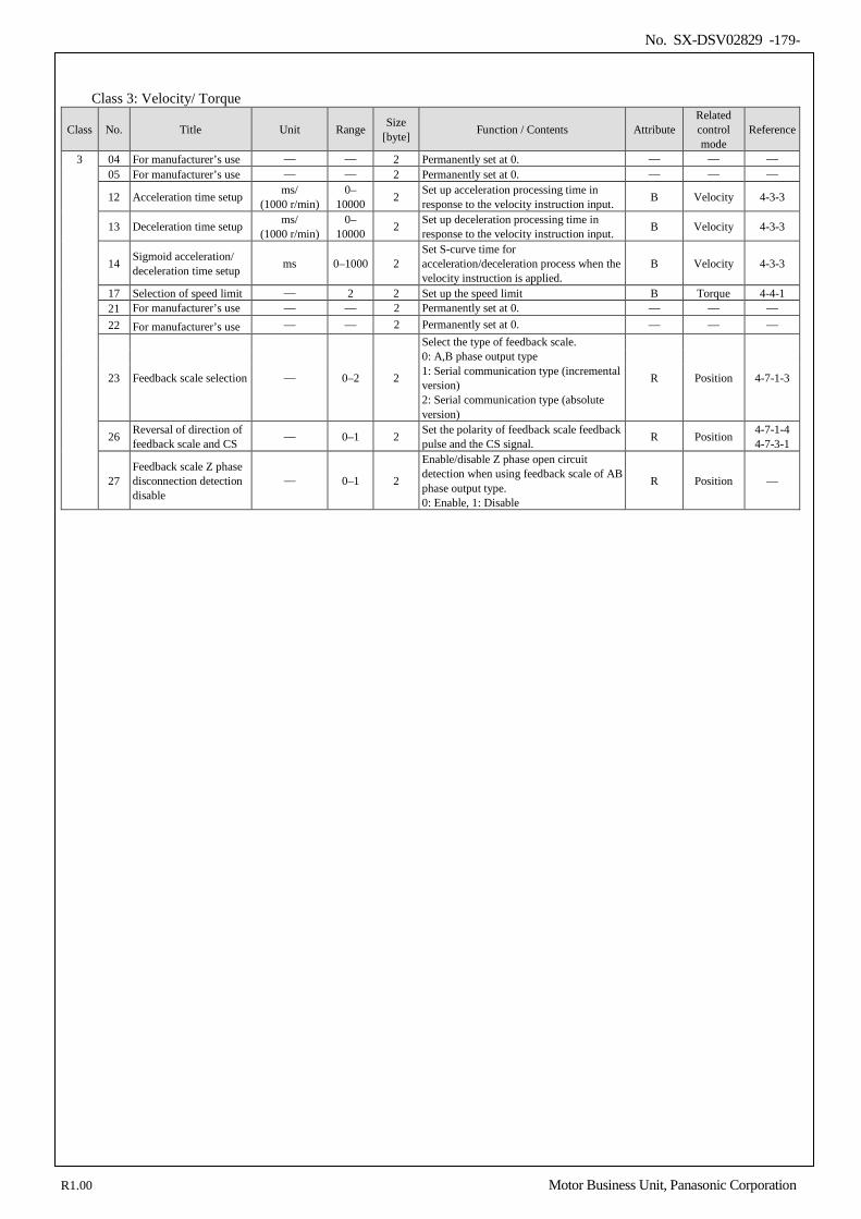
No. SX-DSV02829 -179-
Class 3: Velocity/ Torque
Class No. Title Unit Range Size [byte] Function / Contents Attribute
Related control mode
Reference
3 04 For manufacturer’s use — — 2 Permanently set at 0. — — — 05 For manufacturer’s use — — 2 Permanently set at 0. — — —
12 Acceleration time setup ms/ (1000 r/min)
0– 10000 2 Set up acceleration processing time in
response to the velocity instruction input. B Velocity 4-3-3
13 Deceleration time setup ms/ (1000 r/min)
0– 10000 2 Set up deceleration processing time in
response to the velocity instruction input. B Velocity 4-3-3
14 Sigmoid acceleration/ deceleration time setup ms 0–1000 2
Set S-curve time for acceleration/deceleration process when the velocity instruction is applied.
B Velocity 4-3-3
17 Selection of speed limit — 2 2 Set up the speed limit B Torque 4-4-1 21 For manufacturer’s use — — 2 Permanently set at 0. — — — 22 For manufacturer’s use — — 2 Permanently set at 0. — — —
23 Feedback scale selection — 0–2 2
Select the type of feedback scale. 0: A,B phase output type 1: Serial communication type (incremental version) 2: Serial communication type (absolute version)
R Position 4-7-1-3
26 Reversal of direction of feedback scale and CS
— 0–1 2 Set the polarity of feedback scale feedback pulse and the CS signal. R Position 4-7-1-4
4-7-3-1
27 Feedback scale Z phase disconnection detection disable
— 0–1 2
Enable/disable Z phase open circuit detection when using feedback scale of AB phase output type. 0: Enable, 1: Disable
R Position —
R1.00 Motor Business Unit, Panasonic Corporation
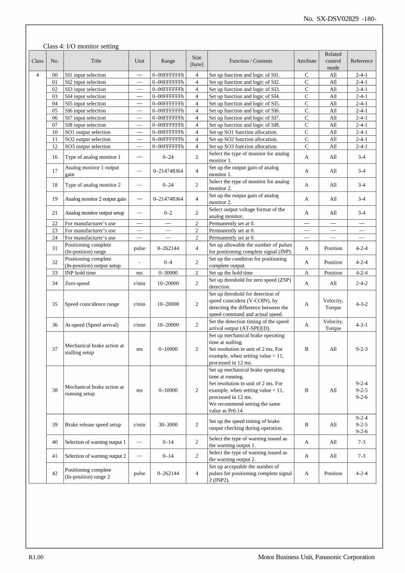
No. SX-DSV02829 -180-
Class 4: I/O monitor setting
Class No. Title Unit Range Size [byte] Function / Contents Attribute
Related control mode
Reference
4 00 SI1 input selection — 0–00FFFFFFh 4 Set up function and logic of SI1. C All 2-4-1 01 SI2 input selection — 0–00FFFFFFh 4 Set up function and logic of SI2. C All 2-4-1 02 SI3 input selection — 0–00FFFFFFh 4 Set up function and logic of SI3. C All 2-4-1 03 SI4 input selection — 0–00FFFFFFh 4 Set up function and logic of SI4. C All 2-4-1 04 SI5 input selection — 0–00FFFFFFh 4 Set up function and logic of SI5. C All 2-4-1 05 SI6 input selection — 0–00FFFFFFh 4 Set up function and logic of SI6. C All 2-4-1 06 SI7 input selection — 0–00FFFFFFh 4 Set up function and logic of SI7. C All 2-4-1 07 SI8 input selection — 0–00FFFFFFh 4 Set up function and logic of SI8. C All 2-4-1 10 SO1 output selection — 0–00FFFFFFh 4 Set up SO1 function allocation. C All 2-4-1 11 SO2 output selection — 0–00FFFFFFh 4 Set up SO2 function allocation. C All 2-4-1 12 SO3 output selection — 0–00FFFFFFh 4 Set up SO3 function allocation. C All 2-4-1
16 Type of analog monitor 1 — 0–24 2 Select the type of monitor for analog monitor 1. A All 3-4
17 Analog monitor 1 output gain
— 0–214748364 4 Set up the output gain of analog monitor 1. A All 3-4
18 Type of analog monitor 2 — 0–24 2 Select the type of monitor for analog monitor 2. A All 3-4
19 Analog monitor 2 output gain — 0–214748364 4 Set up the output gain of analog monitor 2. A All 3-4
21 Analog monitor output setup — 0–2 2 Select output voltage format of the analog monitor. A All 3-4
22 For manufacturer’s use — — 2 Permanently set at 0. — — — 23 For manufacturer’s use — — 2 Permanently set at 0. — — — 24 For manufacturer’s use — — 2 Permanently set at 0. — — —
31 Positioning complete (In-position) range pulse 0–262144 4 Set up allowable the number of pulses
for positioning complete signal (INP). A Position 4-2-4
32 Positioning complete (In-position) output setup - 0–4 2 Set up the condition for positioning
complete output. A Position 4-2-4
33 INP hold time ms 0–30000 2 Set up the hold time A Position 4-2-4
34 Zero-speed r/min 10–20000 2 Set up threshold for zero speed (ZSP) detection. A All 2-4-2
35 Speed coincidence range r/min 10–20000 2
Set up threshold for detection of speed coincident (V-COIN), by detecting the difference between the speed command and actual speed.
A Velocity, Torque 4-3-2
36 At-speed (Speed arrival) r/min 10–20000 2 Set the detection timing of the speed arrival output (AT-SPEED). A Velocity,
Torque 4-3-1
37 Mechanical brake action at stalling setup ms 0–10000 2
Set up mechanical brake operating time at stalling. Set resolution in unit of 2 ms. For example, when setting value = 11, processed in 12 ms.
B All 9-2-3
38 Mechanical brake action at running setup ms 0–10000 2
Set up mechanical brake operating time at running. Set resolution in unit of 2 ms. For example, when setting value = 11, processed in 12 ms. We recommend setting the same value as Pr6.14.
B All 9-2-4 9-2-5 9-2-6
39 Brake release speed setup r/min 30–3000 2 Set up the speed timing of brake output checking during operation. B All
9-2-4 9-2-5 9-2-6
40 Selection of warning output 1 — 0–14 2 Select the type of warning issued as the warning output 1. A All 7-3
41 Selection of warning output 2 — 0–14 2 Select the type of warning issued as the warning output 2. A All 7-3
42 Positioning complete (In-position) range 2 pulse 0–262144 4
Set up acceptable the number of pulses for positioning complete signal 2 (INP2).
A Position 4-2-4
R1.00 Motor Business Unit, Panasonic Corporation
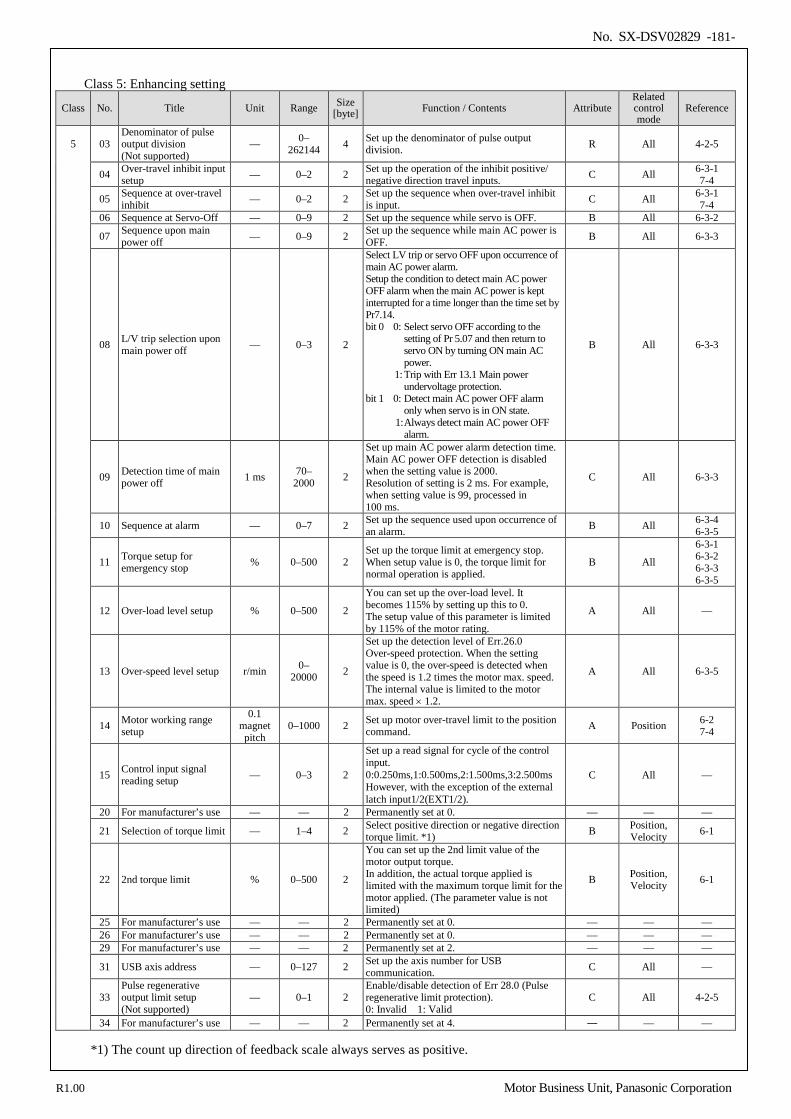
No. SX-DSV02829 -181-
Class 5: Enhancing setting
Class No. Title Unit Range Size [byte] Function / Contents Attribute
Related control mode
Reference
5 03 Denominator of pulse output division (Not supported)
— 0– 262144 4 Set up the denominator of pulse output
division. R All 4-2-5
04 Over-travel inhibit input setup — 0–2 2 Set up the operation of the inhibit positive/
negative direction travel inputs. C All 6-3-1 7-4
05 Sequence at over-travel inhibit — 0–2 2 Set up the sequence when over-travel inhibit
is input. C All 6-3-1 7-4
06 Sequence at Servo-Off — 0–9 2 Set up the sequence while servo is OFF. B All 6-3-2
07 Sequence upon main power off — 0–9 2 Set up the sequence while main AC power is
OFF. B All 6-3-3
08 L/V trip selection upon main power off — 0–3 2
Select LV trip or servo OFF upon occurrence of main AC power alarm. Setup the condition to detect main AC power OFF alarm when the main AC power is kept interrupted for a time longer than the time set by Pr7.14. bit 0 0: Select servo OFF according to the
setting of Pr 5.07 and then return to servo ON by turning ON main AC power.
1: Trip with Err 13.1 Main power undervoltage protection.
bit 1 0: Detect main AC power OFF alarm only when servo is in ON state.
1: Always detect main AC power OFF alarm.
B All 6-3-3
09 Detection time of main power off 1 ms 70–
2000 2
Set up main AC power alarm detection time. Main AC power OFF detection is disabled when the setting value is 2000. Resolution of setting is 2 ms. For example, when setting value is 99, processed in 100 ms.
C All 6-3-3
10 Sequence at alarm — 0–7 2 Set up the sequence used upon occurrence of an alarm. B All 6-3-4
6-3-5
11 Torque setup for emergency stop % 0–500 2
Set up the torque limit at emergency stop. When setup value is 0, the torque limit for normal operation is applied.
B All
6-3-1 6-3-2 6-3-3 6-3-5
12 Over-load level setup % 0–500 2
You can set up the over-load level. It becomes 115% by setting up this to 0. The setup value of this parameter is limited by 115% of the motor rating.
A All —
13 Over-speed level setup r/min 0– 20000 2
Set up the detection level of Err.26.0 Over-speed protection. When the setting value is 0, the over-speed is detected when the speed is 1.2 times the motor max. speed. The internal value is limited to the motor max. speed × 1.2.
A All 6-3-5
14 Motor working range setup
0.1 magnet pitch
0–1000 2 Set up motor over-travel limit to the position command. A Position 6-2
7-4
15 Control input signal reading setup — 0–3 2
Set up a read signal for cycle of the control input. 0:0.250ms,1:0.500ms,2:1.500ms,3:2.500ms However, with the exception of the external latch input1/2(EXT1/2).
C All —
20 For manufacturer’s use — — 2 Permanently set at 0. — — —
21 Selection of torque limit — 1–4 2 Select positive direction or negative direction torque limit. *1) B Position,
Velocity 6-1
22 2nd torque limit % 0–500 2
You can set up the 2nd limit value of the motor output torque. In addition, the actual torque applied is limited with the maximum torque limit for the motor applied. (The parameter value is not limited)
B Position, Velocity 6-1
25 For manufacturer’s use — — 2 Permanently set at 0. — — — 26 For manufacturer’s use — — 2 Permanently set at 0. — — — 29 For manufacturer’s use — — 2 Permanently set at 2. — — —
31 USB axis address — 0–127 2 Set up the axis number for USB communication. C All —
33 Pulse regenerative output limit setup (Not supported)
— 0–1 2 Enable/disable detection of Err 28.0 (Pulse regenerative limit protection). 0: Invalid 1: Valid
C All 4-2-5
34 For manufacturer’s use — — 2 Permanently set at 4. ― — — *1) The count up direction of feedback scale always serves as positive.
R1.00 Motor Business Unit, Panasonic Corporation
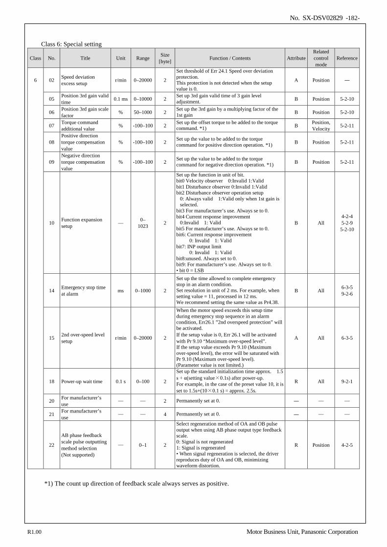
No. SX-DSV02829 -182-
Class 6: Special setting
Class No. Title Unit Range Size [byte] Function / Contents Attribute
Related control mode
Reference
6 02 Speed deviation excess setup r/min 0–20000 2
Set threshold of Err 24.1 Speed over deviation protection. This protection is not detected when the setup value is 0.
A Position ―
05 Position 3rd gain valid time 0.1 ms 0–10000 2 Set up 3rd gain valid time of 3 gain level
adjustment. B Position 5-2-10
06 Position 3rd gain scale factor % 50–1000 2 Set up the 3rd gain by a multiplying factor of the
1st gain B Position 5-2-10
07 Torque command additional value % -100–100 2 Set up the offset torque to be added to the torque
command. *1) B Position, Velocity 5-2-11
08 Positive direction torque compensation value
% -100–100 2 Set up the value to be added to the torque command for positive direction operation. *1) B Position 5-2-11
09 Negative direction torque compensation value
% -100–100 2 Set up the value to be added to the torque command for negative direction operation. *1) B Position 5-2-11
10 Function expansion setup — 0–
1023 2
Set up the function in unit of bit. bit0 Velocity observer 0:Invalid 1:Valid bit1 Disturbance observer 0:Invalid 1:Valid bit2 Disturbance observer operation setup
0: Always valid 1:Valid only when 1st gain is selected.
bit3 For manufacturer’s use. Always se to 0. bit4 Current response improvement
0:Invalid 1: Valid bit5 For manufacturer’s use. Always se to 0. bit6: Current response improvement
0: Invalid 1: Valid bit7: INP output limit
0: Invalid 1: Valid bit8:unused. Always set to 0. bit9: For manufacturer’s use. Always set to 0. • bit 0 = LSB
B All 4-2-4 5-2-9
5-2-10
14 Emergency stop time at alarm ms 0–1000 2
Set up the time allowed to complete emergency stop in an alarm condition. Set resolution in unit of 2 ms. For example, when setting value = 11, processed in 12 ms. We recommend setting the same value as Pr4.38.
B All 6-3-5 9-2-6
15 2nd over-speed level setup r/min 0–20000 2
When the motor speed exceeds this setup time during emergency stop sequence in an alarm condition, Err26.1 ”2nd overspeed protection” will be activated. If the setup value is 0, Err 26.1 will be activated with Pr 9.10 “Maximum over-speed level”. If the setup value exceeds Pr 9.10 (Maximum over-speed level), the error will be saturated with Pr 9.10 (Maximum over-speed level). (Parameter value is not limited.)
A All 6-3-5
18 Power-up wait time 0.1 s 0–100 2
Set up the standard initialization time approx. 1.5 s + α(setting value×0.1s) after power-up. For example, in the case of the preset value 10, it is set to 1.5s+(10×0.1 s) = approx. 2.5s.
R All 9-2-1
20 For manufacturer’s use
— — 2 Permanently set at 0. ― — —
21 For manufacturer’s use
— — 4 Permanently set at 0. ― — —
22
AB phase feedback scale pulse outputting method selection (Not supported)
— 0–1 2
Select regeneration method of OA and OB pulse output when using AB phase output type feedback scale. 0: Signal is not regenerated 1: Signal is regenerated • When signal regeneration is selected, the driver reproduces duty of OA and OB, minimizing waveform distortion.
R Position 4-2-5
*1) The count up direction of feedback scale always serves as positive.
R1.00 Motor Business Unit, Panasonic Corporation
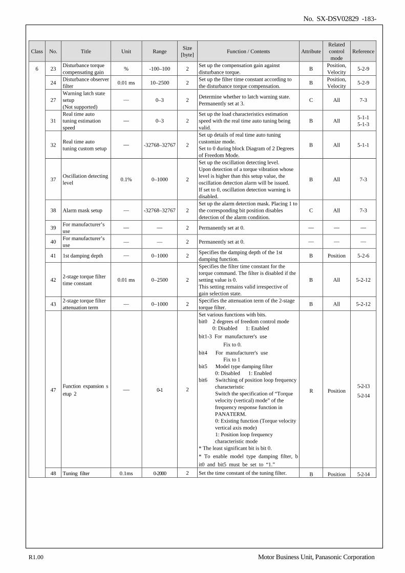
No. SX-DSV02829 -183-
Class No. Title Unit Range Size [byte] Function / Contents Attribute
Related control mode
Reference
6 23 Disturbance torque compensating gain % -100–100 2 Set up the compensation gain against
disturbance torque. B Position, Velocity 5-2-9
24 Disturbance observer filter 0.01 ms 10–2500 2 Set up the filter time constant according to
the disturbance torque compensation. B Position, Velocity 5-2-9
27 Warning latch state setup (Not supported)
— 0–3 2 Determine whether to latch warning state. Permanently set at 3. C All 7-3
31 Real time auto tuning estimation speed
— 0–3 2 Set up the load characteristics estimation speed with the real time auto tuning being valid.
B All 5-1-1 5-1-3
32 Real time auto tuning custom setup
— -32768–32767 2
Set up details of real time auto tuning customize mode. Set to 0 during block Diagram of 2 Degrees of Freedom Mode.
B All 5-1-1
37 Oscillation detecting level 0.1% 0–1000 2
Set up the oscillation detecting level. Upon detection of a torque vibration whose level is higher than this setup value, the oscillation detection alarm will be issued. If set to 0, oscillation detection warning is disabled.
B All 7-3
38 Alarm mask setup — -32768–32767 2 Set up the alarm detection mask. Placing 1 to the corresponding bit position disables detection of the alarm condition.
C All 7-3
39 For manufacturer’s use
— — 2 Permanently set at 0. — — —
40 For manufacturer’s use — — 2 Permanently set at 0. — — —
41 1st damping depth — 0−1000 2 Specifies the damping depth of the 1st damping function. B Position 5-2-6
42 2-stage torque filter time constant 0.01 ms 0−2500 2
Specifies the filter time constant for the torque command. The filter is disabled if the setting value is 0. This setting remains valid irrespective of gain selection state.
B All 5-2-12
43 2-stage torque filter attenuation term — 0−1000 2 Specifies the attenuation term of the 2-stage
torque filter. B All 5-2-12
47 Function expansion setup 2
— 0-1 2
Set various functions with bits. bit0 2 degrees of freedom control mode 0: Disabled 1: Enabled bit1-3 For manufacturer's use Fix to 0. bit4 For manufacturer's use Fix to 1 bit5 Model type damping filter 0: Disabled 1: Enabled
bit6 Switching of position loop frequency characteristic
Switch the specification of “Torque velocity (vertical) mode” of the frequency response function in PANATERM.
0: Existing function (Torque velocity vertical axis mode)
1: Position loop frequency characteristic mode
* The least significant bit is bit 0. * To enable model type damping filter, bit0 and bit5 must be set to “1.”
R Position 5-2-13
5-2-14
48 Tuning filter 0.1ms 0-2000 2 Set the time constant of the tuning filter. B Position 5-2-14
R1.00 Motor Business Unit, Panasonic Corporation
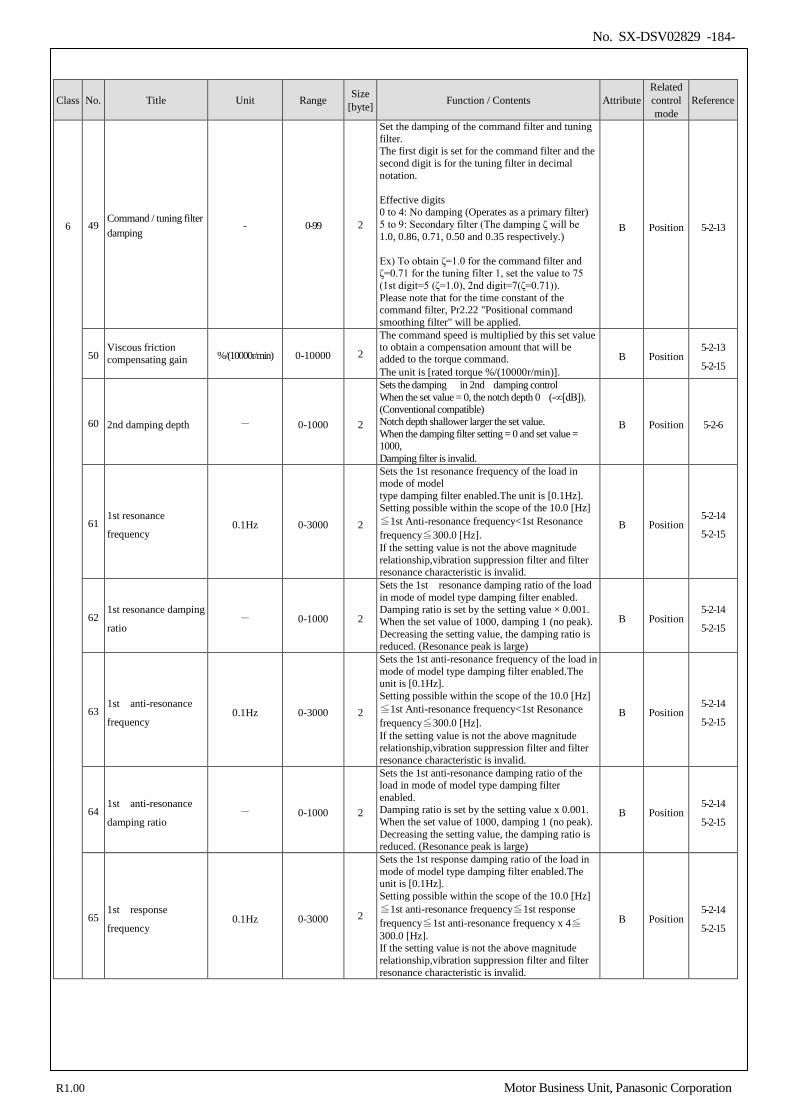
No. SX-DSV02829 -184-
Class No. Title Unit Range Size [byte] Function / Contents Attribute
Related control mode
Reference
6 49 Command / tuning filter damping
- 0-99 2
Set the damping of the command filter and tuning filter. The first digit is set for the command filter and the second digit is for the tuning filter in decimal notation. Effective digits 0 to 4: No damping (Operates as a primary filter) 5 to 9: Secondary filter (The damping ζ will be 1.0, 0.86, 0.71, 0.50 and 0.35 respectively.) Ex) To obtain ζ=1.0 for the command filter and ζ=0.71 for the tuning filter 1, set the value to 75 (1st digit=5 (ζ=1.0), 2nd digit=7(ζ=0.71)). Please note that for the time constant of the command filter, Pr2.22 "Positional command smoothing filter" will be applied.
B Position 5-2-13
50 Viscous friction compensating gain %/(10000r/min) 0-10000 2
The command speed is multiplied by this set value to obtain a compensation amount that will be added to the torque command. The unit is [rated torque %/(10000r/min)].
B Position 5-2-13
5-2-15
60 2nd damping depth - 0-1000 2
Sets the damping in 2nd damping control When the set value = 0, the notch depth 0 (-∞[dB]). (Conventional compatible) Notch depth shallower larger the set value. When the damping filter setting = 0 and set value = 1000, Damping filter is invalid.
B Position 5-2-6
61 1st resonance
frequency 0.1Hz 0-3000 2
Sets the 1st resonance frequency of the load in mode of model type damping filter enabled.The unit is [0.1Hz]. Setting possible within the scope of the 10.0 [Hz]≦1st Anti-resonance frequency<1st Resonance frequency≦300.0 [Hz]. If the setting value is not the above magnitude relationship,vibration suppression filter and filter resonance characteristic is invalid.
B Position 5-2-14
5-2-15
62 1st resonance damping
ratio - 0-1000 2
Sets the 1st resonance damping ratio of the load in mode of model type damping filter enabled. Damping ratio is set by the setting value × 0.001. When the set value of 1000, damping 1 (no peak). Decreasing the setting value, the damping ratio is reduced. (Resonance peak is large)
B Position 5-2-14
5-2-15
63 1st anti-resonance
frequency 0.1Hz 0-3000 2
Sets the 1st anti-resonance frequency of the load in mode of model type damping filter enabled.The unit is [0.1Hz]. Setting possible within the scope of the 10.0 [Hz]≦1st Anti-resonance frequency<1st Resonance frequency≦300.0 [Hz]. If the setting value is not the above magnitude relationship,vibration suppression filter and filter resonance characteristic is invalid.
B Position 5-2-14
5-2-15
64 1st anti-resonance
damping ratio - 0-1000 2
Sets the 1st anti-resonance damping ratio of the load in mode of model type damping filter enabled. Damping ratio is set by the setting value x 0.001. When the set value of 1000, damping 1 (no peak). Decreasing the setting value, the damping ratio is reduced. (Resonance peak is large)
B Position 5-2-14
5-2-15
65 1st response
frequency 0.1Hz 0-3000 2
Sets the 1st response damping ratio of the load in mode of model type damping filter enabled.The unit is [0.1Hz]. Setting possible within the scope of the 10.0 [Hz]≦1st anti-resonance frequency≦1st response frequency≦1st anti-resonance frequency x 4≦300.0 [Hz]. If the setting value is not the above magnitude relationship,vibration suppression filter and filter resonance characteristic is invalid.
B Position 5-2-14
5-2-15
R1.00 Motor Business Unit, Panasonic Corporation
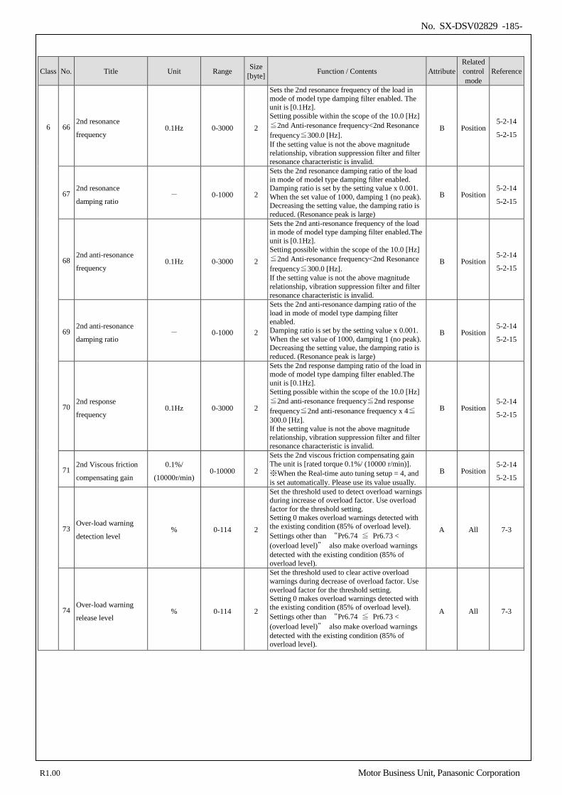
No. SX-DSV02829 -185-
Class No. Title Unit Range Size [byte] Function / Contents Attribute
Related control mode
Reference
6 66 2nd resonance
frequency 0.1Hz 0-3000 2
Sets the 2nd resonance frequency of the load in mode of model type damping filter enabled. The unit is [0.1Hz]. Setting possible within the scope of the 10.0 [Hz]≦2nd Anti-resonance frequency<2nd Resonance frequency≦300.0 [Hz]. If the setting value is not the above magnitude relationship, vibration suppression filter and filter resonance characteristic is invalid.
B Position 5-2-14
5-2-15
67 2nd resonance
damping ratio - 0-1000 2
Sets the 2nd resonance damping ratio of the load in mode of model type damping filter enabled. Damping ratio is set by the setting value x 0.001. When the set value of 1000, damping 1 (no peak). Decreasing the setting value, the damping ratio is reduced. (Resonance peak is large)
B Position 5-2-14
5-2-15
68 2nd anti-resonance
frequency 0.1Hz 0-3000 2
Sets the 2nd anti-resonance frequency of the load in mode of model type damping filter enabled.The unit is [0.1Hz]. Setting possible within the scope of the 10.0 [Hz]≦2nd Anti-resonance frequency<2nd Resonance frequency≦300.0 [Hz]. If the setting value is not the above magnitude relationship, vibration suppression filter and filter resonance characteristic is invalid.
B Position 5-2-14
5-2-15
69 2nd anti-resonance
damping ratio - 0-1000 2
Sets the 2nd anti-resonance damping ratio of the load in mode of model type damping filter enabled. Damping ratio is set by the setting value x 0.001. When the set value of 1000, damping 1 (no peak). Decreasing the setting value, the damping ratio is reduced. (Resonance peak is large)
B Position 5-2-14
5-2-15
70 2nd response
frequency 0.1Hz 0-3000 2
Sets the 2nd response damping ratio of the load in mode of model type damping filter enabled.The unit is [0.1Hz]. Setting possible within the scope of the 10.0 [Hz]≦2nd anti-resonance frequency≦2nd response frequency≦2nd anti-resonance frequency x 4≦300.0 [Hz]. If the setting value is not the above magnitude relationship, vibration suppression filter and filter resonance characteristic is invalid.
B Position 5-2-14
5-2-15
71 2nd Viscous friction
compensating gain
0.1%/
(10000r/min) 0-10000 2
Sets the 2nd viscous friction compensating gain The unit is [rated torque 0.1%/ (10000 r/min)]. ※When the Real-time auto tuning setup = 4, and is set automatically. Please use its value usually.
B Position 5-2-14
5-2-15
73 Over-load warning
detection level % 0-114 2
Set the threshold used to detect overload warnings during increase of overload factor. Use overload factor for the threshold setting. Setting 0 makes overload warnings detected with the existing condition (85% of overload level). Settings other than “Pr6.74 ≦ Pr6.73 < (overload level)” also make overload warnings detected with the existing condition (85% of overload level).
A All 7-3
74 Over-load warning
release level % 0-114 2
Set the threshold used to clear active overload warnings during decrease of overload factor. Use overload factor for the threshold setting. Setting 0 makes overload warnings detected with the existing condition (85% of overload level). Settings other than “Pr6.74 ≦ Pr6.73 < (overload level)” also make overload warnings detected with the existing condition (85% of overload level).
A All 7-3
R1.00 Motor Business Unit, Panasonic Corporation
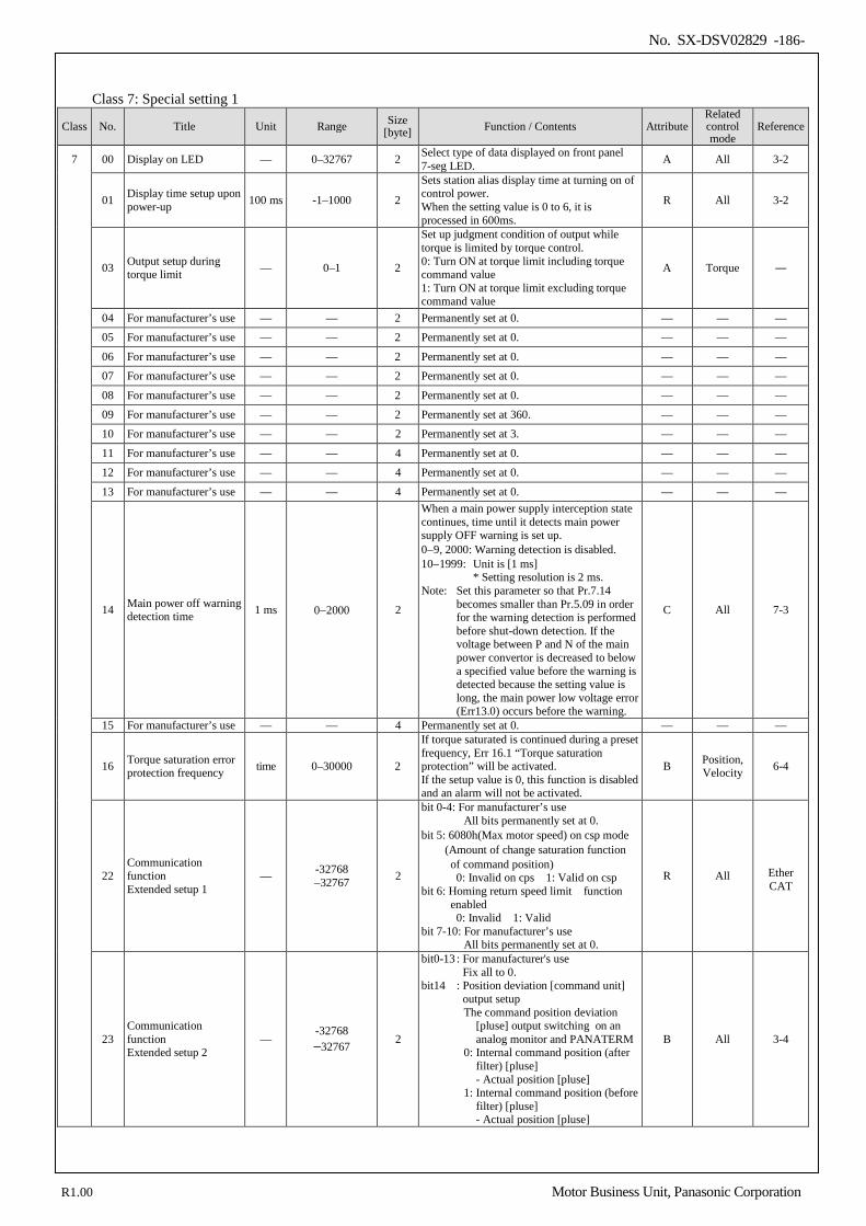
No. SX-DSV02829 -186-
Class 7: Special setting 1
Class No. Title Unit Range Size [byte] Function / Contents Attribute
Related control mode
Reference
7 00 Display on LED — 0–32767 2 Select type of data displayed on front panel 7-seg LED. A All 3-2
01 Display time setup upon power-up 100 ms -1–1000 2
Sets station alias display time at turning on of control power. When the setting value is 0 to 6, it is processed in 600ms.
R All 3-2
03 Output setup during torque limit — 0–1 2
Set up judgment condition of output while torque is limited by torque control. 0: Turn ON at torque limit including torque command value 1: Turn ON at torque limit excluding torque command value
A Torque ―
04 For manufacturer’s use — — 2 Permanently set at 0. — — — 05 For manufacturer’s use — — 2 Permanently set at 0. — — —
06 For manufacturer’s use — — 2 Permanently set at 0. — — — 07 For manufacturer’s use — — 2 Permanently set at 0. — — —
08 For manufacturer’s use — — 2 Permanently set at 0. — — — 09 For manufacturer’s use — — 2 Permanently set at 360. — — — 10 For manufacturer’s use — — 2 Permanently set at 3. — — —
11 For manufacturer’s use — — 4 Permanently set at 0. — — — 12 For manufacturer’s use — — 4 Permanently set at 0. — — —
13 For manufacturer’s use — — 4 Permanently set at 0. — — —
14 Main power off warning detection time 1 ms 0−2000 2
When a main power supply interception state continues, time until it detects main power supply OFF warning is set up. 0−9, 2000: Warning detection is disabled. 10−1999: Unit is [1 ms]
* Setting resolution is 2 ms. Note: Set this parameter so that Pr.7.14
becomes smaller than Pr.5.09 in order for the warning detection is performed before shut-down detection. If the voltage between P and N of the main power convertor is decreased to below a specified value before the warning is detected because the setting value is long, the main power low voltage error (Err13.0) occurs before the warning.
C All 7-3
15 For manufacturer’s use — — 4 Permanently set at 0. — — —
16 Torque saturation error protection frequency time 0–30000 2
If torque saturated is continued during a preset frequency, Err 16.1 “Torque saturation protection” will be activated. If the setup value is 0, this function is disabled and an alarm will not be activated.
B Position, Velocity 6-4
22 Communication function Extended setup 1
— -32768 –32767 2
bit 0-4: For manufacturer’s use All bits permanently set at 0.
bit 5: 6080h(Max motor speed) on csp mode (Amount of change saturation function
of command position) 0: Invalid on cps 1: Valid on csp
bit 6: Homing return speed limit function enabled 0: Invalid 1: Valid
bit 7-10: For manufacturer’s use All bits permanently set at 0.
R All Ether CAT
23 Communication function Extended setup 2
— -32768 –32767 2
bit0-13 : For manufacturer's use Fix all to 0.
bit14 : Position deviation [command unit] output setup The command position deviation
[pluse] output switching on an analog monitor and PANATERM
0: Internal command position (after filter) [pluse] - Actual position [pluse]
1: Internal command position (before filter) [pluse] - Actual position [pluse]
B All 3-4
R1.00 Motor Business Unit, Panasonic Corporation
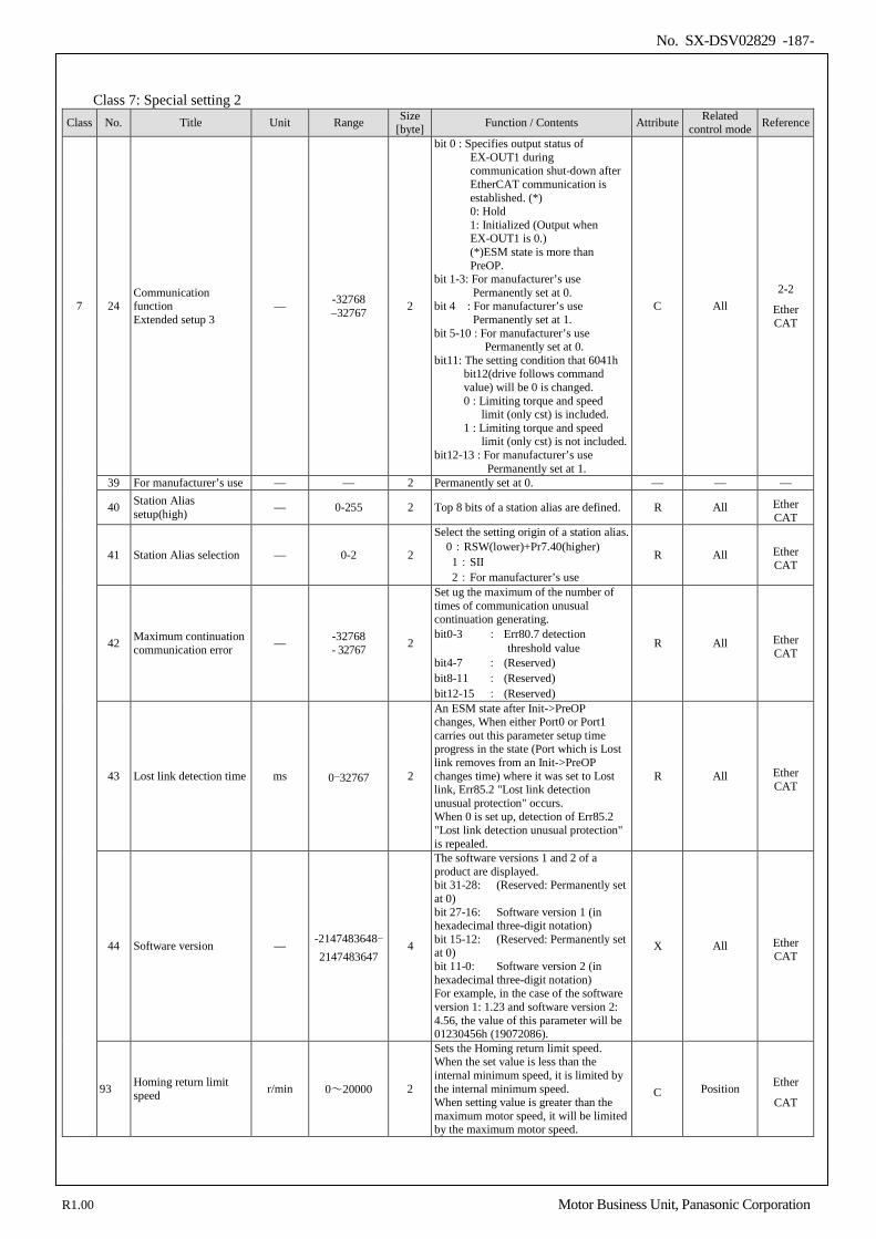
No. SX-DSV02829 -187-
Class 7: Special setting 2
Class No. Title Unit Range Size [byte] Function / Contents Attribute Related
control mode Reference
7 24 Communication function Extended setup 3
— -32768 –32767 2
bit 0 : Specifies output status of EX-OUT1 during communication shut-down after EtherCAT communication is established. (*) 0: Hold 1: Initialized (Output when EX-OUT1 is 0.) (*)ESM state is more than PreOP.
bit 1-3: For manufacturer’s use Permanently set at 0.
bit 4 : For manufacturer’s use Permanently set at 1.
bit 5-10 : For manufacturer’s use Permanently set at 0.
bit11: The setting condition that 6041h bit12(drive follows command
value) will be 0 is changed. 0 : Limiting torque and speed
limit (only cst) is included. 1 : Limiting torque and speed
limit (only cst) is not included. bit12-13 : For manufacturer’s use
Permanently set at 1.
C All 2-2
Ether CAT
39 For manufacturer’s use — — 2 Permanently set at 0. — — —
40 Station Alias setup(high) — 0-255 2 Top 8 bits of a station alias are defined. R All Ether
CAT
41 Station Alias selection — 0-2 2
Select the setting origin of a station alias. 0:RSW(lower)+Pr7.40(higher) 1:SII 2:For manufacturer’s use
R All Ether CAT
42 Maximum continuation communication error — -32768
- 32767 2
Set ug the maximum of the number of times of communication unusual continuation generating. bit0-3 : Err80.7 detection
threshold value bit4-7 : (Reserved) bit8-11 : (Reserved) bit12-15 : (Reserved)
R All Ether CAT
43 Lost link detection time ms 0-32767 2
An ESM state after Init->PreOP changes, When either Port0 or Port1 carries out this parameter setup time progress in the state (Port which is Lost link removes from an Init->PreOP changes time) where it was set to Lost link, Err85.2 "Lost link detection unusual protection" occurs. When 0 is set up, detection of Err85.2 "Lost link detection unusual protection" is repealed.
R All Ether CAT
44 Software version — -2147483648- 2147483647
4
The software versions 1 and 2 of a product are displayed. bit 31-28: (Reserved: Permanently set at 0) bit 27-16: Software version 1 (in hexadecimal three-digit notation) bit 15-12: (Reserved: Permanently set at 0) bit 11-0: Software version 2 (in hexadecimal three-digit notation) For example, in the case of the software version 1: 1.23 and software version 2: 4.56, the value of this parameter will be 01230456h (19072086).
X All Ether CAT
93 Homing return limit speed r/min 0~20000 2
Sets the Homing return limit speed. When the set value is less than the internal minimum speed, it is limited by the internal minimum speed. When setting value is greater than the maximum motor speed, it will be limited by the maximum motor speed.
C Position Ether
CAT
R1.00 Motor Business Unit, Panasonic Corporation
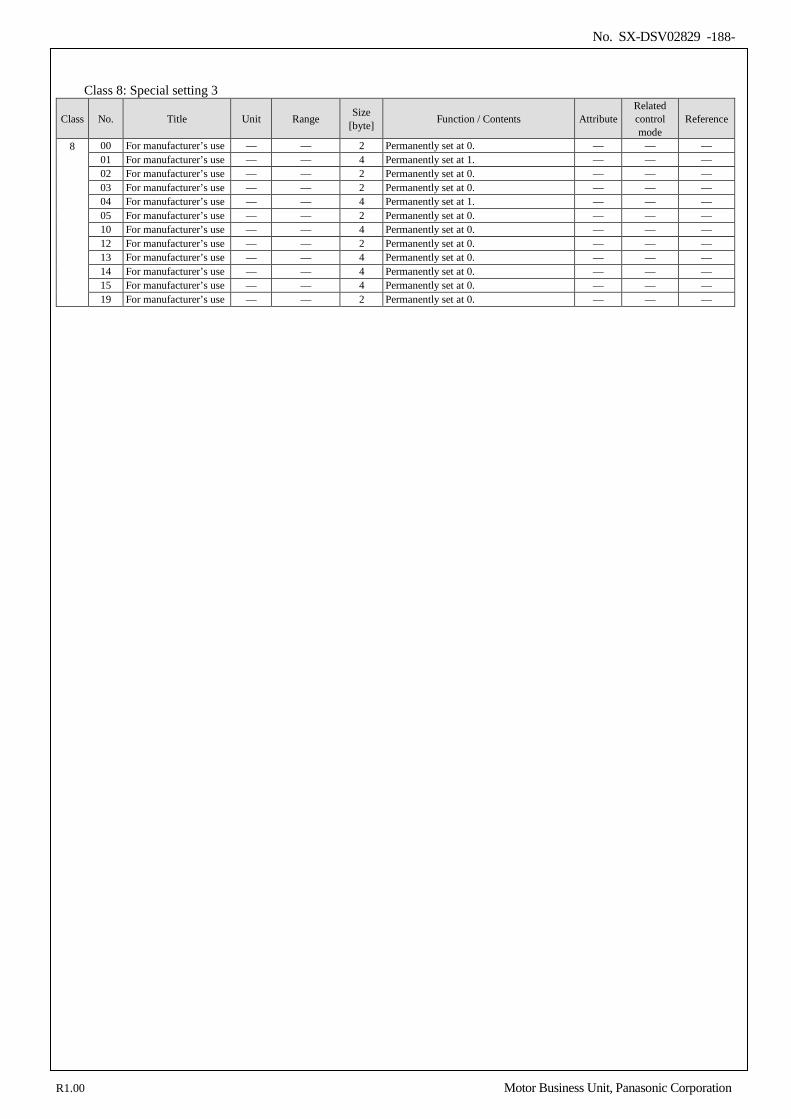
No. SX-DSV02829 -188-
Class 8: Special setting 3
Class No. Title Unit Range Size [byte] Function / Contents Attribute
Related control mode
Reference
8 00 For manufacturer’s use — — 2 Permanently set at 0. — — — 01 For manufacturer’s use — — 4 Permanently set at 1. — — — 02 For manufacturer’s use — — 2 Permanently set at 0. — — — 03 For manufacturer’s use — — 2 Permanently set at 0. — — — 04 For manufacturer’s use — — 4 Permanently set at 1. — — — 05 For manufacturer’s use — — 2 Permanently set at 0. — — — 10 For manufacturer’s use — — 4 Permanently set at 0. — — — 12 For manufacturer’s use — — 2 Permanently set at 0. — — — 13 For manufacturer’s use — — 4 Permanently set at 0. — — — 14 For manufacturer’s use — — 4 Permanently set at 0. — — — 15 For manufacturer’s use — — 4 Permanently set at 0. — — — 19 For manufacturer’s use — — 2 Permanently set at 0. — — —
R1.00 Motor Business Unit, Panasonic Corporation
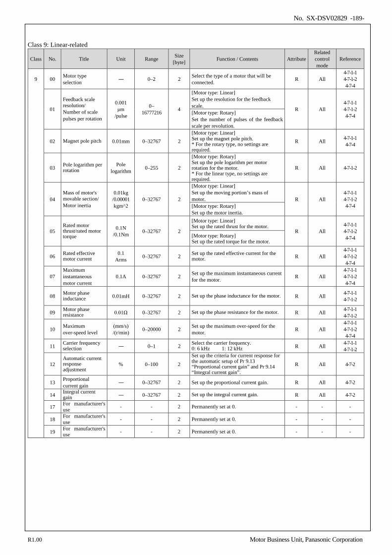
No. SX-DSV02829 -189-
Class 9: Linear-related
Class No. Title Unit Range Size [byte] Function / Contents Attribute
Related control mode
Reference
9 00 Motor type selection ― 0–2 2 Select the type of a motor that will be
connected. R All 4-7-1-1 4-7-1-2 4-7-4
01
Feedback scale resolution/ Number of scale pulses per rotation
0.001 μm
/pulse
0– 16777216 4
[Motor type: Linear] Set up the resolution for the feedback scale. R All
4-7-1-1 4-7-1-2 4-7-4 [Motor type: Rotary]
Set the number of pulses of the feedback scale per revolution.
02 Magnet pole pitch 0.01mm 0–32767 2 [Motor type: Linear] Set up the magnet pole pitch. * For the rotary type, no settings are required.
R All 4-7-1-1 4-7-4
03 Pole logarithm per rotation
Pole logarithm 0–255 2
[Motor type: Rotary] Set up the pole logarithm per motor rotation for the motor. * For the linear type, no settings are required.
R All 4-7-1-2
04 Mass of motor's movable section/ Motor inertia
0.01kg /0.00001 kgm^2
0–32767 2
[Motor type: Linear] Set up the moving portion’s mass of motor. R All
4-7-1-1 4-7-1-2 4-7-4 [Motor type: Rotary]
Set up the motor inertia.
05 Rated motor thrust/rated motor torque
0.1N /0.1Nm 0–32767 2
[Motor type: Linear] Set up the rated thrust for the motor.
R All 4-7-1-1 4-7-1-2 4-7-4 [Motor type: Rotary]
Set up the rated torque for the motor.
06 Rated effective motor current
0.1 Arms 0–32767 2 Set up the rated effective current for the
motor. R All 4-7-1-1 4-7-1-2 4-7-4
07 Maximum instantaneous motor current
0.1A 0–32767 2 Set up the maximum instantaneous current for the motor. R All
4-7-1-1 4-7-1-2 4-7-4
08 Motor phase inductance 0.01mH 0–32767 2 Set up the phase inductance for the motor. R All 4-7-1-1
4-7-1-2
09 Motor phase resistance 0.01Ω 0–32767 2 Set up the phase resistance for the motor. R All 4-7-1-1
4-7-1-2
10 Maximum over-speed level
(mm/s) /(r/min) 0–20000 2 Set up the maximum over-speed for the
motor. R All 4-7-1-1 4-7-1-2 4-7-4
11 Carrier frequency selection ― 0–1 2 Select the carrier frequency.
0: 6 kHz 1: 12 kHz R All 4-7-1-1 4-7-1-2
12 Automatic current response adjustment
% 0–100 2
Set up the criteria for current response for the automatic setup of Pr 9.13 “Proportional current gain” and Pr 9.14 “Integral current gain”.
R All 4-7-2
13 Proportional current gain ― 0–32767 2 Set up the proportional current gain. R All 4-7-2
14 Integral current gain ― 0–32767 2 Set up the integral current gain. R All 4-7-2
17 For manufacturer's use - - 2 Permanently set at 0. - - -
18 For manufacturer's use - - 2 Permanently set at 0. - - -
19 For manufacturer's use - - 2 Permanently set at 0. - - -
R1.00 Motor Business Unit, Panasonic Corporation
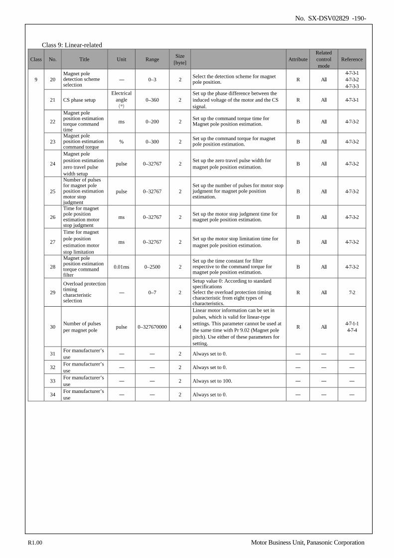
No. SX-DSV02829 -190-
Class 9: Linear-related
Class No. Title Unit Range Size [byte] Attribute
Related control mode
Reference
9 20 Magnet pole detection scheme selection
― 0–3 2 Select the detection scheme for magnet pole position. R All
4-7-3-1 4-7-3-2 4-7-3-3
21 CS phase setup Electrical
angle (°)
0–360 2 Set up the phase difference between the induced voltage of the motor and the CS signal.
R All 4-7-3-1
22
Magnet pole position estimation torque command time
ms 0–200 2 Set up the command torque time for Magnet pole position estimation. B All 4-7-3-2
23 Magnet pole position estimation command torque
% 0–300 2 Set up the command torque for magnet pole position estimation. B All 4-7-3-2
24
Magnet pole position estimation zero travel pulse width setup
pulse 0–32767 2 Set up the zero travel pulse width for magnet pole position estimation. B All 4-7-3-2
25
Number of pulses for magnet pole position estimation motor stop judgment
pulse 0–32767 2 Set up the number of pulses for motor stop judgment for magnet pole position estimation.
B All 4-7-3-2
26
Time for magnet pole position estimation motor stop judgment
ms 0–32767 2 Set up the motor stop judgment time for magnet pole position estimation. B All 4-7-3-2
27
Time for magnet pole position estimation motor stop limitation
ms 0–32767 2 Set up the motor stop limitation time for magnet pole position estimation. B All 4-7-3-2
28
Magnet pole position estimation torque command filter
0.01ms 0–2500 2 Set up the time constant for filter respective to the command torque for magnet pole position estimation.
B All 4-7-3-2
29
Overload protection timing characteristic selection
― 0–7 2
Setup value 0: According to standard specifications Select the overload protection timing characteristic from eight types of characteristics.
R All 7-2
30 Number of pulses per magnet pole pulse 0–327670000 4
Linear motor information can be set in pulses, which is valid for linear-type settings. This parameter cannot be used at the same time with Pr 9.02 (Magnet pole pitch). Use either of these parameters for setting.
R All 4-7-1-1 4-7-4
31 For manufacturer’s use ― ― 2 Always set to 0. ― ― ―
32 For manufacturer’s use ― ― 2 Always set to 0. ― ― ―
33 For manufacturer’s use ― ― 2 Always set to 100. ― ― ―
34 For manufacturer’s use ― ― 2 Always set to 0. ― ― ―
R1.00 Motor Business Unit, Panasonic Corporation
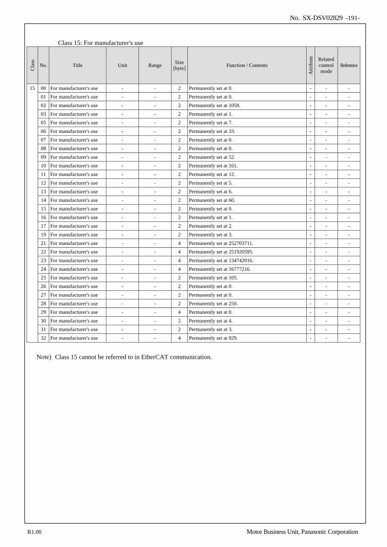
No. SX-DSV02829 -191-
Class 15: For manufacturer's use
Cla
ss
No. Title Unit Range Size [byte] Function / Contents
Attr
ibut
e Related control mode
Reference
15 00 For manufacturer's use - - 2 Permanently set at 0. - - - 01 For manufacturer's use - - 2 Permanently set at 0. - - - 02 For manufacturer's use - - 2 Permanently set at 1058. - - -
03 For manufacturer's use - - 2 Permanently set at 1. - - - 05 For manufacturer's use - - 2 Permanently set at 7. - - -
06 For manufacturer's use - - 2 Permanently set at 33. - - - 07 For manufacturer's use - - 2 Permanently set at 0. - - - 08 For manufacturer's use - - 2 Permanently set at 0. - - -
09 For manufacturer's use - - 2 Permanently set at 52. - - - 10 For manufacturer's use - - 2 Permanently set at 161. - - -
11 For manufacturer's use - - 2 Permanently set at 12. - - - 12 For manufacturer's use - - 2 Permanently set at 5. - - -
13 For manufacturer's use - - 2 Permanently set at 6. - - - 14 For manufacturer's use - - 2 Permanently set at 60. - - - 15 For manufacturer's use - - 2 Permanently set at 0. - - -
16 For manufacturer's use - - 2 Permanently set at 1. - - - 17 For manufacturer's use - - 2 Permanently set at 2. - - -
19 For manufacturer's use - - 2 Permanently set at 3. - - - 21 For manufacturer's use - - 4 Permanently set at 252703711. - - - 22 For manufacturer's use - - 4 Permanently set at 251920595. - - -
23 For manufacturer's use - - 4 Permanently set at 134742016. - - - 24 For manufacturer's use - - 4 Permanently set at 16777216. - - -
25 For manufacturer's use - - 2 Permanently set at 105. - - - 26 For manufacturer's use - - 2 Permanently set at 0. - - -
27 For manufacturer's use - - 2 Permanently set at 0. - - - 28 For manufacturer's use - - 2 Permanently set at 250. - - - 29 For manufacturer's use - - 4 Permanently set at 0. - - -
30 For manufacturer's use - - 2 Permanently set at 4. - - - 31 For manufacturer's use - - 2 Permanently set at 3. - - -
32 For manufacturer's use - - 4 Permanently set at 929. - - -
Note) Class 15 cannot be referred to in EtherCAT communication.
R1.00 Motor Business Unit, Panasonic Corporation
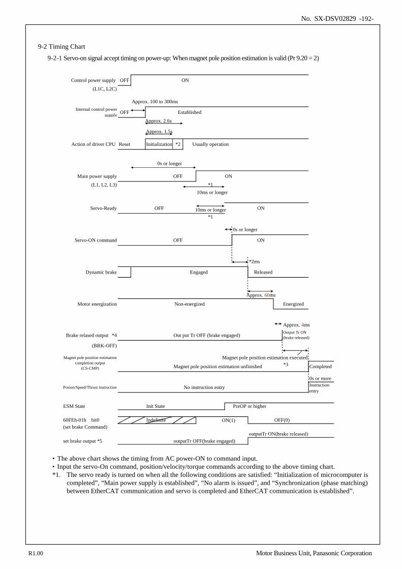
No. SX-DSV02829 -192-
9-2 Timing Chart
9-2-1 Servo-on signal accept timing on power-up: When magnet pole position estimation is valid (Pr 9.20 = 2)
Control power supply OFF ON
(L1C, L2C)
Approx. 100 to 300msInternal control power
supply OFF Established
Approx. 2.6s
Approx. 1.5s
Action of driver CPU Reset Initialization *2 Usually operation
0s or longer
Main power supply OFF ON
(L1, L2, L3) *1
Servo-Ready OFF 10ms or longer ON
*1
0s or longer
Servo-ON command OFF ON
*2ms
Dynamic brake Engaged Released
Approx. 60ms
Motor energization Non-energized Energized
Approx. 4ms
Brake relased output *4 Out put Tr OFF (brake engaged)
(BRK-OFF)
Magnet pole position estimation executed
Magnet pole position estimation unfinished *3 Completed
0s or more
Posion/Speed/Thrust instruction No instruction entry
ESM State Init State PreOP or higher
60FEh-01h bit0 Indefinite ON(1) OFF(0)(set brake Command)
outputTr ON(brake released)set brake output *5 outputTr OFF(brake engaged)
Output Tr ON(brake released)
Instructionentry
Magnet pole position estimationcompletion output
(CS-CMP)
10ms or longer
• The above chart shows the timing from AC power-ON to command input. • Input the servo-On command, position/velocity/torque commands according to the above timing chart. *1. The servo ready is turned on when all the following conditions are satisfied: “Initialization of microcomputer is
completed”, “Main power supply is established”, “No alarm is issued”, and “Synchronization (phase matching) between EtherCAT communication and servo is completed and EtherCAT communication is established”.
R1.00 Motor Business Unit, Panasonic Corporation
No. SX-DSV02829 -193-
*2. After Internal control power supply, protective functions are active from approx. 1.5 sec after the start of
initializing microcomputer. Please set the signals, especially for protective function, for example over-travel inhibit input (POT, NOT) or external scale input, so as to decide their logic until this term. The lapse time can be changed with Pr 6.18 Wait time after power-up.
*3. Time for magnet pole position estimation depends on parameter settings. Check that the magnet pole position estimation completion output will turn ON and then apply the command. If magnet pole position estimation has not completed correctly, the magnet pole position estimation completion output will not turn ON.
*4. A brake release output (BRK-OFF) is different from the set brake of 60FEh via EtherCAT communication. *5. The set brake output is output controlled by the set brake of 60FEh via EtherCAT communication.
For information on the set brake output details, refer to the section 6-9-3 in the Technical Reference EtherCAT Communication Specification (SX-DSV02830). The set brake output can be released in the servo-off state.Therefore, In consideration of safety, please control
the set brake output.
R1.00 Motor Business Unit, Panasonic Corporation
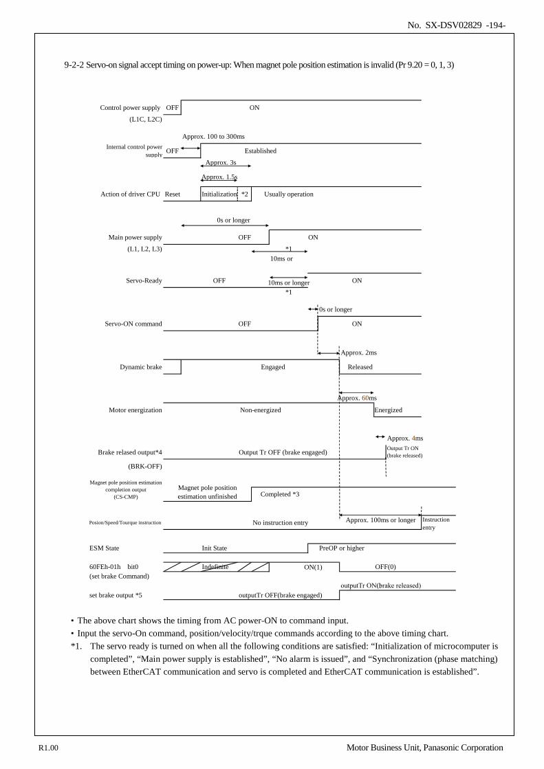
No. SX-DSV02829 -194-
9-2-2 Servo-on signal accept timing on power-up: When magnet pole position estimation is invalid (Pr 9.20 = 0, 1, 3)
Control power supply OFF ON
(L1C, L2C)
Approx. 100 to 300msInternal control power
supply OFF Established
Approx. 3s
Approx. 1.5s
Action of driver CPU Reset Initialization *2 Usually operation
0s or longer
Main power supply OFF ON
(L1, L2, L3) *1
Servo-Ready OFF 10ms or longer ON
*1
0s or longer
Servo-ON command OFF ON
Approx. 2ms
Dynamic brake Engaged Released
Approx. 60ms
Motor energization Non-energized Energized
Approx. 4ms
Brake relased output*4 Output Tr OFF (brake engaged)
(BRK-OFF)
Posion/Speed/Tourque instruction No instruction entry
ESM State Init State PreOP or higher
60FEh-01h bit0 Indefinite ON(1) OFF(0)(set brake Command)
outputTr ON(brake released)set brake output *5 outputTr OFF(brake engaged)
Output Tr ON(brake released)
Instructionentry
Magnet pole position estimationcompletion output
(CS-CMP)Magnet pole positionestimation unfinished
Approx. 100ms or longer
Completed *3
10ms or
• The above chart shows the timing from AC power-ON to command input. • Input the servo-On command, position/velocity/trque commands according to the above timing chart. *1. The servo ready is turned on when all the following conditions are satisfied: “Initialization of microcomputer is
completed”, “Main power supply is established”, “No alarm is issued”, and “Synchronization (phase matching) between EtherCAT communication and servo is completed and EtherCAT communication is established”.
R1.00 Motor Business Unit, Panasonic Corporation
No. SX-DSV02829 -195-
*2. After Internal control power supply, protective functions are active from approx. 1.5 sec after the start of
initializing microcomputer. Please set the signals, especially for protective function, for example over-travel inhibit input (POT, NOT) or feedback scale input, so as to decide their logic until this term. The lapse time can be changed with Pr 6.18 “Wait time after power-up”.
*3. If Err 61.2 “Magnet pole position estimation error 3 protection” is activated or with Pr 9.20 = 0, the magnet pole position estimation completion output will not turn ON. The timing (condition) at which the magnet pole position estimation completion output turns ON depends on the setup value for Pr 9.20 “Magnet pole detection scheme selection”. For more information, refer to Section 2-2
*4. A brake release output (BRK-OFF) is different from the set brake of 60FEh via EtherCAT communication. *5. The set brake output is output controlled by the set brake of 60FEh via EtherCAT communication.
For information on the set brake output details, refer to the section 6-9-3 in the Technical Reference EtherCAT Communication Specification (SX-DSV02830). The set brake output can be released in the servo-off state.Therefore, In consideration of safety, please control
the set brake output.
R1.00 Motor Business Unit, Panasonic Corporation
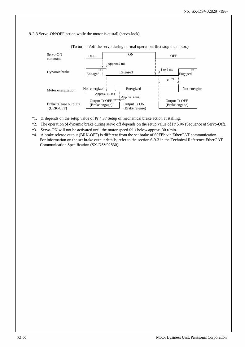
No. SX-DSV02829 -196-
9-2-3 Servo-ON/OFF action while the motor is at stall (servo-lock)
(To turn on/off the servo during normal operation, first stop the motor.)
Approx. 60 ms
Servo-ON command
Dynamic brake
Motor energization
Brake release output*4 (BRK-OFF)
OFF ON
Released
Energized
Output Tr ON (Brake release)
Engaged
Output Tr OFF (Brake engage)
Not-energized
Engaged
Approx.2 ms
1 to 6 ms
t1 *1
*2
Not-energize
*3
Approx. 4 ms Output Tr OFF
(Brake engage)
OFF
*1. t1 depends on the setup value of Pr 4.37 Setup of mechanical brake action at stalling. *2. The operation of dynamic brake during servo off depends on the setup value of Pr 5.06 (Sequence at Servo-Off). *3. Servo-ON will not be activated until the motor speed falls below approx. 30 r/min. *4. A brake release output (BRK-OFF) is different from the set brake of 60FEh via EtherCAT communication.
For information on the set brake output details, refer to the section 6-9-3 in the Technical Reference EtherCAT Communication Specification (SX-DSV02830).
R1.00 Motor Business Unit, Panasonic Corporation
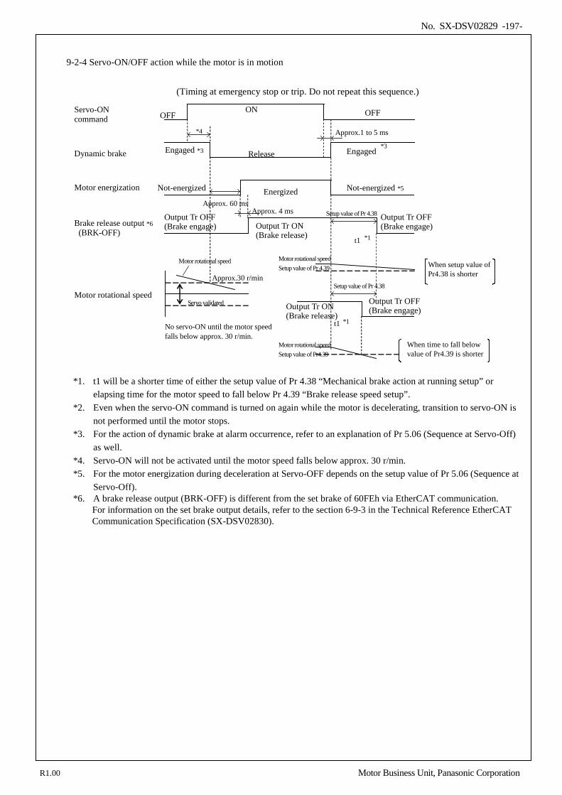
No. SX-DSV02829 -197-
9-2-4 Servo-ON/OFF action while the motor is in motion
(Timing at emergency stop or trip. Do not repeat this sequence.)
Approx. 60 ms
Servo-ON command
Dynamic brake
Motor energization
Brake release output *6 (BRK-OFF)
OFF
ON
Release
Energized
Output Tr ON (Brake release)
Engaged
Output Tr OFF (Brake engage)
Not-energized
Engaged *3
Setup value of Pr 4.38
Approx.1 to 5 ms
t1 *1
*3
Not-energized *5
*4
Approx. 4 ms
Motor rotational speed
Approx.30 r/min
Servo validated
Motor rotational speed Setup value of Pr 4.39
Setup value of Pr 4.38
t1 *1 No servo-ON until the motor speed falls below approx. 30 r/min.
Motor rotational speed
When setup value of Pr4.38 is shorter
When time to fall below value of Pr4.39 is shorter
Motor rotational speed Setup value of Pr4.39
OFF
Output Tr OFF (Brake engage)
Output Tr ON (Brake release)
Output Tr OFF (Brake engage)
*1. t1 will be a shorter time of either the setup value of Pr 4.38 “Mechanical brake action at running setup” or
elapsing time for the motor speed to fall below Pr 4.39 “Brake release speed setup”. *2. Even when the servo-ON command is turned on again while the motor is decelerating, transition to servo-ON is
not performed until the motor stops. *3. For the action of dynamic brake at alarm occurrence, refer to an explanation of Pr 5.06 (Sequence at Servo-Off)
as well. *4. Servo-ON will not be activated until the motor speed falls below approx. 30 r/min. *5. For the motor energization during deceleration at Servo-OFF depends on the setup value of Pr 5.06 (Sequence at
Servo-Off). *6. A brake release output (BRK-OFF) is different from the set brake of 60FEh via EtherCAT communication. For information on the set brake output details, refer to the section 6-9-3 in the Technical Reference EtherCAT Communication Specification (SX-DSV02830).
R1.00 Motor Business Unit, Panasonic Corporation
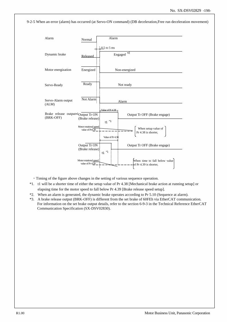
No. SX-DSV02829 -198-
9-2-5 When an error (alarm) has occurred (at Servo-ON command) (DB deceleration,Free run deceleration movement)
Alarm
Dynamic brake
Motor energization
Brake release output*3 (BRK-OFF)
Normal
Engaged
Non-energized
Output Tr ON (Brake release)
Energized
Released
0.5 to 5 ms *2
Motor rotational speed value of Pr4.39
Value of Pr 4.38
t1 *1
Motor rotational speed value of Pr 4.39
When setup value of Pr 4.38 is shorter,
When time to fall below value of Pr 4.39 is shorter,
Servo-Ready
Not Alarm
Servo-Alarm output (ALM)
Value of Pr 4.38
t1 *1
Not ready
Alarm
Output Tr OFF (Brake engage)
Output Tr ON (Brake release)
Output Tr OFF (Brake engage)
Alarm
Ready
・Timing of the figure above changes in the setting of various sequence operation.
*1. t1 will be a shorter time of either the setup value of Pr 4.38 [Mechanical brake action at running setup] or elapsing time for the motor speed to fall below Pr 4.39 [Brake release speed setup].
*2. When an alarm is generated, the dynamic brake operates according to Pr 5.10 (Sequence at alarm). *3. A brake release output (BRK-OFF) is different from the set brake of 60FEh via EtherCAT communication. For information on the set brake output details, refer to the section 6-9-3 in the Technical Reference EtherCAT Communication Specification (SX-DSV02830).
R1.00 Motor Business Unit, Panasonic Corporation
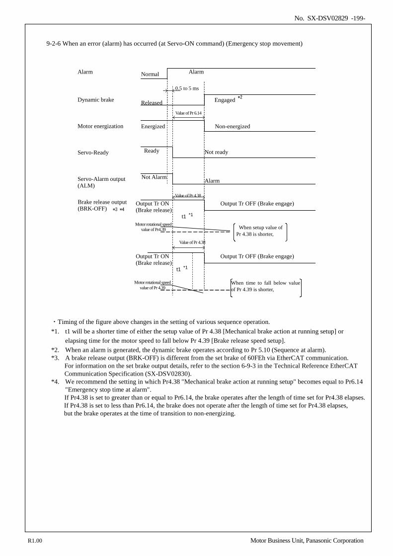
No. SX-DSV02829 -199-
9-2-6 When an error (alarm) has occurred (at Servo-ON command) (Emergency stop movement)
Alarm
Dynamic brake
Motor energization
Brake release output (BRK-OFF)
Normal
Engaged
Non-energized
Output Tr ON (Brake release)
Energized
Released
0.5 to 5 ms *2
Motor rotational speed value of Pr4.39
Value of Pr 4.38
t1 *1
Motor rotational speed value of Pr 4.39
When setup value of Pr 4.38 is shorter,
When time to fall below value of Pr 4.39 is shorter,
Servo-Ready
Not Alarm
Servo-Alarm output (ALM)
Value of Pr 4.38
t1 *1
Not ready
Alarm
Output Tr OFF (Brake engage)
Output Tr ON (Brake release)
Output Tr OFF (Brake engage)
Alarm
Ready
Value of Pr 6.14
*3 *4
・Timing of the figure above changes in the setting of various sequence operation. *1. t1 will be a shorter time of either the setup value of Pr 4.38 [Mechanical brake action at running setup] or
elapsing time for the motor speed to fall below Pr 4.39 [Brake release speed setup]. *2. When an alarm is generated, the dynamic brake operates according to Pr 5.10 (Sequence at alarm). *3. A brake release output (BRK-OFF) is different from the set brake of 60FEh via EtherCAT communication. For information on the set brake output details, refer to the section 6-9-3 in the Technical Reference EtherCAT Communication Specification (SX-DSV02830). *4. We recommend the setting in which Pr4.38 "Mechanical brake action at running setup" becomes equal to Pr6.14
"Emergency stop time at alarm". If Pr4.38 is set to greater than or equal to Pr6.14, the brake operates after the length of time set for Pr4.38 elapses.
If Pr4.38 is set to less than Pr6.14, the brake does not operate after the length of time set for Pr4.38 elapses, but the brake operates at the time of transition to non-energizing.
R1.00 Motor Business Unit, Panasonic Corporation
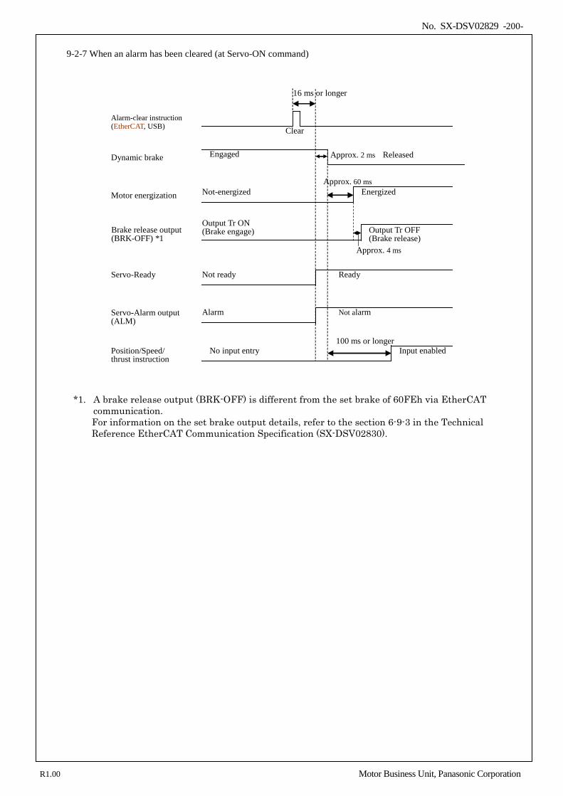
No. SX-DSV02829 -200-
9-2-7 When an alarm has been cleared (at Servo-ON command)
Alarm-clear instruction (EtherCAT, USB)
Dynamic brake
Motor energization
Brake release output (BRK-OFF) *1
Engaged
Not-energized
Output Tr OFF (Brake release)
Energized
Servo-Ready
Servo-Alarm output (ALM)
Approx. 60 ms
Approx. 4 ms
No input entry Input enabled Position/Speed/ thrust instruction
100 ms or longer
Approx. 2 ms Released
Clear
Output Tr ON (Brake engage)
Not ready Ready
Alarm Not alarm
16 ms or longer
*1. A brake release output (BRK-OFF) is different from the set brake of 60FEh via EtherCAT communication. For information on the set brake output details, refer to the section 6-9-3 in the Technical Reference EtherCAT Communication Specification (SX-DSV02830).
R1.00 Motor Business Unit, Panasonic Corporation