uc-hmi readme firstuc-hmi...
TRANSCRIPT
Copyright © 2017 FLAT Display Technology Corporatio n. All rights reserved. Add: No.85, Sec. 1, Fuxing Rd., South Dist., Taichu ng City 402, Taiwan (R.O.C.) http:// www.fdt.com.tw E-mail: [email protected]
Tel: 886-4-22619577, Fax: 886-4-2 2623978
uC-HMI ReadMe First (日本語版)
Version ::::1.0
Date::::September 1, 2017
ReadMe First
Copyright © 2017 FDT http:// www.fdt.com.tw, E-mail- [email protected]
This technical specification is subject to change without notice
1
2017 09 01 V1.0
第1章第1章第1章第1章 uC-HMI (Micro Controller HMI) Start Kit の紹介の紹介の紹介の紹介 ........................... 2
1.1 まえがきまえがきまえがきまえがき ................................................................................................................................. 2
1.2 Frame Diagram (uC-HMI + func.)................. ......................................................................... 2
1.3 uC-HMI Development Process .................... ......................................................................... 3
1.4 uC-HMI User Window ............................ ................................................................................ 4
第2章第2章第2章第2章 uC-HMI Start Kit の説明の説明の説明の説明 ................................................................. 5
2.1 P/N of Start Kit .............................. ......................................................................................... 5
2.2 Accessories ................................... ........................................................................................ 6
2.3 Index in CD of uC-HMI ......................... ................................................................................. 9
第3章第3章第3章第3章 Start Kit の評価の評価の評価の評価 .............................................................................. 10
3.1 Demo Mode ..................................... ..................................................................................... 10
3.2 UART Mode ..................................... ..................................................................................... 10
第4章第4章第4章第4章 開発プロセス開発プロセス開発プロセス開発プロセス ................................................................................ 12
4.1 Development process ........................... .............................................................................. 12
第5章第5章第5章第5章 基本的および上級開発のための技術資料基本的および上級開発のための技術資料基本的および上級開発のための技術資料基本的および上級開発のための技術資料 ..................................... 16
5.1 Basic Development Items ....................... ............................................................................ 16
5.2 Advanced Development Items .................... ....................................................................... 17
Appendix A: How to update profile. (uC_HMI.BIN) Tak e 7" module as reference ................ 18
Contents
ReadMe First
Copyright © 2017 FDT http:// www.fdt.com.tw, E-mail- [email protected]
This technical specification is subject to change without notice
2
2017 09 01 V1.0
第1章第1章第1章第1章 uC-HMI (Micro Controller HMI) スタートキットの紹介スタートキットの紹介スタートキットの紹介スタートキットの紹介
1.1 まえがきまえがきまえがきまえがき
uC-HMI はあらかじめ RAM エリアに定義された変数を上手く使って GUI をコントロールします。
変数にアクセスすることによりユーザーはコマンドプログラミングを簡素化し GUI レイアウトに
集中できるのです。MCU に関連した複雑なコマンドは必要ありません。ディスプレイを制御する変
数にアクセスするだけです。これにより開発スピードは上がり開発コストを低く抑えることがで
きるのです。ユーザーは ReadMe First を見れば次の項目が理解できます。
1. Frame diagram および uC-HMI の開発プロセス
2. ハードウェアの部品およびマニュアル、Application notes and examples.
3. 内蔵されている機能の紹介、 uC-HMIの新しい特徴の体験
4. 必要なツールおよび開発プロセスに適合するマニュアル
5. ツール、Application NotesへのアクセスおよびBasic/ advanced phasesでのツール.
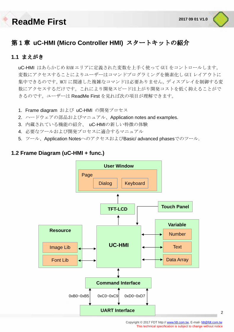
1.2 Frame Diagram (uC-HMI + func.)
User Window Page
TFT-LCD
UC-HMI
Resource
Touch Panel
Variable
Command Interface
UART Interface
Image Lib Text
Data Array
Number
Font Lib
0xB0~0xB5 0xC0~0xC9 0xD0~0xD7
Dialog Keyboard
ReadMe First
Copyright © 2017 FDT http:// www.fdt.com.tw, E-mail- [email protected]
This technical specification is subject to change without notice
3
2017 09 01 V1.0
1. User Window には Page Window, Dialogue and Keyboard が表示されます
2. Resource には Image Lib and Font Lib があります
3. 変数は Number, Text and Data Array に分類されています.
4. Command Interface にはコマンドの動作を変数で用意されています
0xD0~0xD7: Commands of Data Array variables.
0xB0~0xB5 : Commands of number variables.
0xC0~0xC9 : Commands of text variables.
5. UART Interface は MCU との communication のために用意されています.
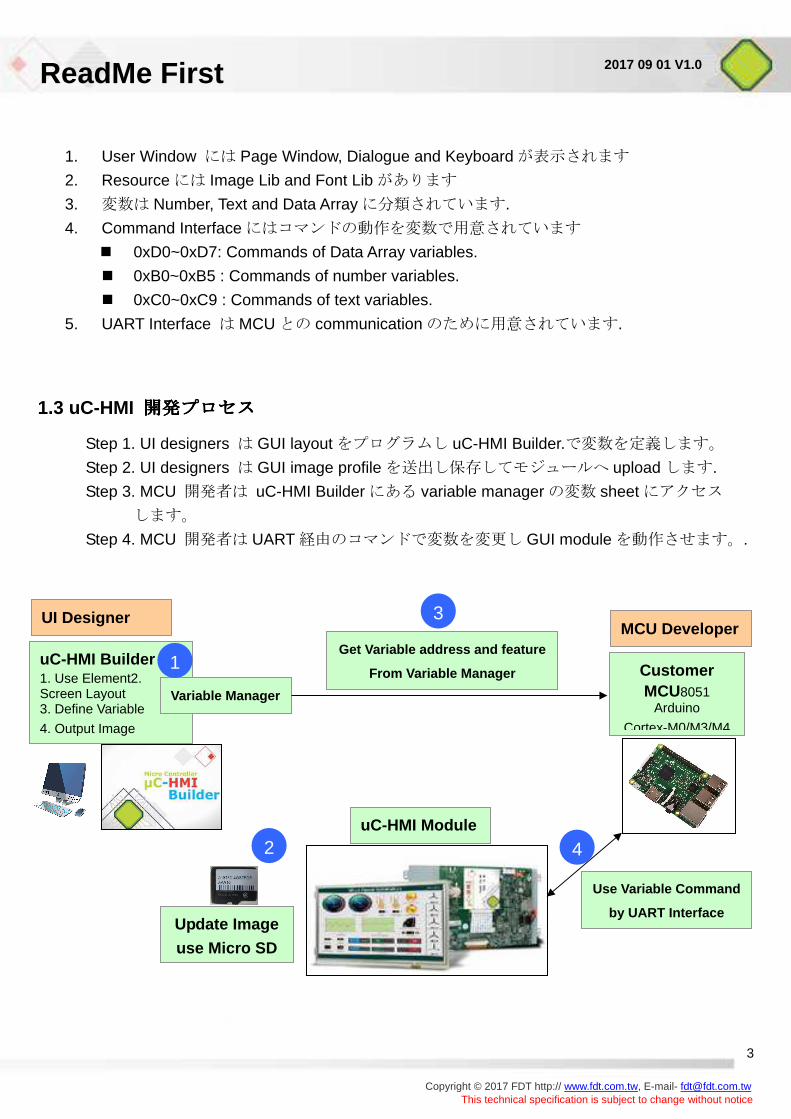
1.3 uC-HMI 開発プロセス開発プロセス開発プロセス開発プロセス
Step 1. UI designers は GUI layout をプログラムし uC-HMI Builder.で変数を定義します。
Step 2. UI designers は GUI image profile を送出し保存してモジュールへ upload します.
Step 3. MCU 開発者は uC-HMI Builder にある variable manager の変数 sheet にアクセス
します。
Step 4. MCU 開発者は UART 経由のコマンドで変数を変更し GUI module を動作させます。.
uC-HMI Builder 1. Use Element2. Screen Layout 3. Define Variable
4. Output Image
Variable Manager
Get Variable address and feature
From Variable Manager Customer MCU8051
Arduino
Cortex-M0/M3/M4
uC-HMI Module
Use Variable Command
by UART Interface Update Image
use Micro SD
1
2
3
4
UI Designer MCU Developer
ReadMe First
Copyright © 2017 FDT http:// www.fdt.com.tw, E-mail- [email protected]
This technical specification is subject to change without notice
4
2017 09 01 V1.0
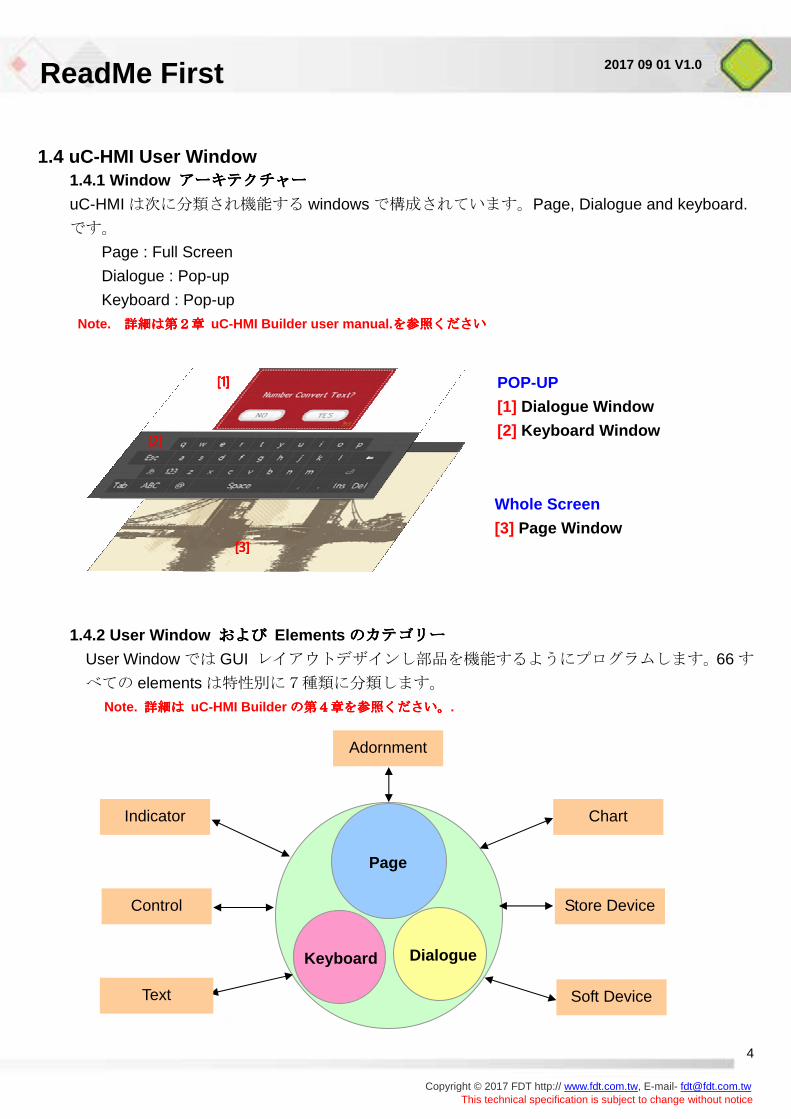
1.4 uC-HMI User Window 1.4.1 Window アーキテクチャアーキテクチャアーキテクチャアーキテクチャーーーー
uC-HMI は次に分類され機能する windows で構成されています。Page, Dialogue and keyboard.
です。
Page : Full Screen
Dialogue : Pop-up
Keyboard : Pop-up
Note. 詳細は第2章詳細は第2章詳細は第2章詳細は第2章 uC-HMI Builder user manual. を参照くださいを参照くださいを参照くださいを参照ください
1.4.2 User Window およびおよびおよびおよび Elements のカテゴリーのカテゴリーのカテゴリーのカテゴリー
User Window では GUI レイアウトデザインし部品を機能するようにプログラムします。66 す
べての elements は特性別に7種類に分類します。
Note. 詳細は詳細は詳細は詳細は uC-HMI Builder の第4章を参照ください。の第4章を参照ください。の第4章を参照ください。の第4章を参照ください。.
Whole Screen
[3] Page Window
POP-UP
[1] Dialogue Window
[2] Keyboard Window
[1][1][1][1]
[2][2][2][2]
[3][3][3][3]
Page
Dialogue Keyboard
Adornment
Soft Device
Store Device
Chart
Control
Indicator
Text
ReadMe First
Copyright © 2017 FDT http:// www.fdt.com.tw, E-mail- [email protected]
This technical specification is subject to change without notice
5
2017 09 01 V1.0
第2章第2章第2章第2章 uC-HMI スタートキットの紹介スタートキットの紹介スタートキットの紹介スタートキットの紹介
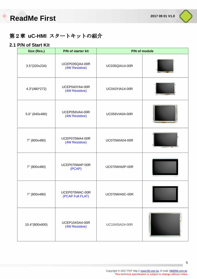
2.1 P/N of Start Kit Size (Res.) P/N of starter kit P/N of module
3.5”(320x234) UCEP035QA4-00R (4W Resistive) UC035QIA14-00R
4.3”(480*272) UCEP043YA4-00R (4W Resistive) UC043YIA14-00R
5.6” (640x480) UCEP056VA4-00R (4W Resistive) UC056VIA04-00R
7” (800x480) UCEP070WA4-00R (4W Resistive) UC070WIA04-00R
7” (800x480) UCEP070WAP-00R (PCAP) UC070WIA0P-00R
7” (800x480) UCEP070WAC-00R (PCAP Full FLAT)
UC070WIA0C-00R
10.4”(800x600) UCEP104SA4-00R (4W Resistive) UC104SIA24-00R
ReadMe First
Copyright © 2017 FDT http:// www.fdt.com.tw, E-mail- [email protected]
This technical specification is subject to change without notice
6
2017 09 01 V1.0
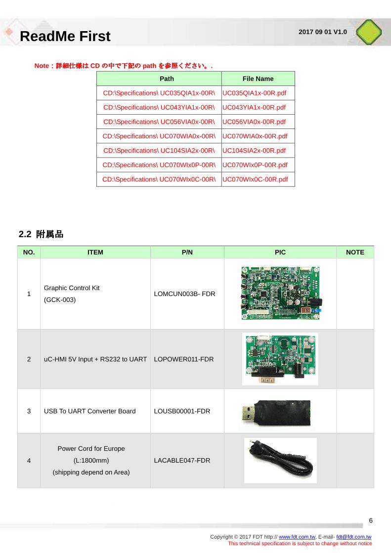
Note::::詳細仕様は詳細仕様は詳細仕様は詳細仕様は CDの中で下記のの中で下記のの中で下記のの中で下記の path を参照ください。を参照ください。を参照ください。を参照ください。.
Path File Name
CD:\Specifications\ UC035QIA1x-00R\ UC035QIA1x-00R.pdf
CD:\Specifications\ UC043YIA1x-00R\ UC043YIA1x-00R.pdf
CD:\Specifications\ UC056VIA0x-00R\ UC056VIA0x-00R.pdf
CD:\Specifications\ UC070WIA0x-00R\ UC070WIA0x-00R.pdf
CD:\Specifications\ UC104SIA2x-00R\ UC104SIA2x-00R.pdf
CD:\Specifications\ UC070WIx0P-00R\ UC070WIx0P-00R.pdf
CD:\Specifications\ UC070WIx0C-00R\ UC070WIx0C-00R.pdf
2.2 附属品附属品附属品附属品
NO. ITEM P/N PIC NOTE
1 Graphic Control Kit
(GCK-003) LOMCUN003B- FDR
2 uC-HMI 5V Input + RS232 to UART LOPOWER011-FDR
3
USB To UART Converter Board
LOUSB00001-FDR
4
Power Cord for Europe
(L:1800mm)
(shipping depend on Area)
LACABLE047-FDR
ReadMe First
Copyright © 2017 FDT http:// www.fdt.com.tw, E-mail- [email protected]
This technical specification is subject to change without notice
7
2017 09 01 V1.0
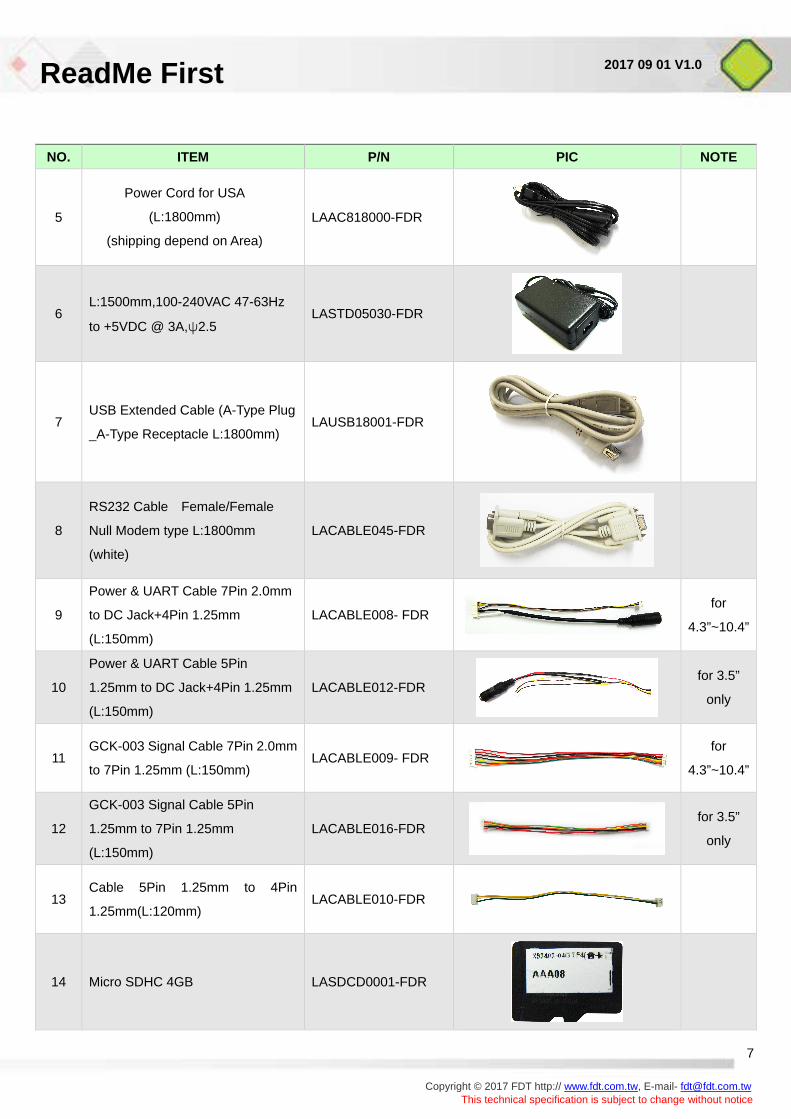
NO. ITEM P/N PIC NOTE
5
Power Cord for USA
(L:1800mm)
(shipping depend on Area)
LAAC818000-FDR
6 L:1500mm,100-240VAC 47-63Hz
to +5VDC @ 3A,ψ2.5 LASTD05030-FDR
7 USB Extended Cable (A-Type Plug
_A-Type Receptacle L:1800mm) LAUSB18001-FDR
8
RS232 Cable Female/Female
Null Modem type L:1800mm
(white)
LACABLE045-FDR
9
Power & UART Cable 7Pin 2.0mm
to DC Jack+4Pin 1.25mm
(L:150mm)
LACABLE008- FDR
for
4.3”~10.4”
10
Power & UART Cable 5Pin
1.25mm to DC Jack+4Pin 1.25mm
(L:150mm)
LACABLE012-FDR
for 3.5”
only
11 GCK-003 Signal Cable 7Pin 2.0mm
to 7Pin 1.25mm (L:150mm) LACABLE009- FDR
for
4.3”~10.4”
12
GCK-003 Signal Cable 5Pin
1.25mm to 7Pin 1.25mm
(L:150mm)
LACABLE016-FDR
for 3.5”
only
13 Cable 5Pin 1.25mm to 4Pin
1.25mm(L:120mm) LACABLE010-FDR
14 Micro SDHC 4GB LASDCD0001-FDR
ReadMe First
Copyright © 2017 FDT http:// www.fdt.com.tw, E-mail- [email protected]
This technical specification is subject to change without notice
8
2017 09 01 V1.0
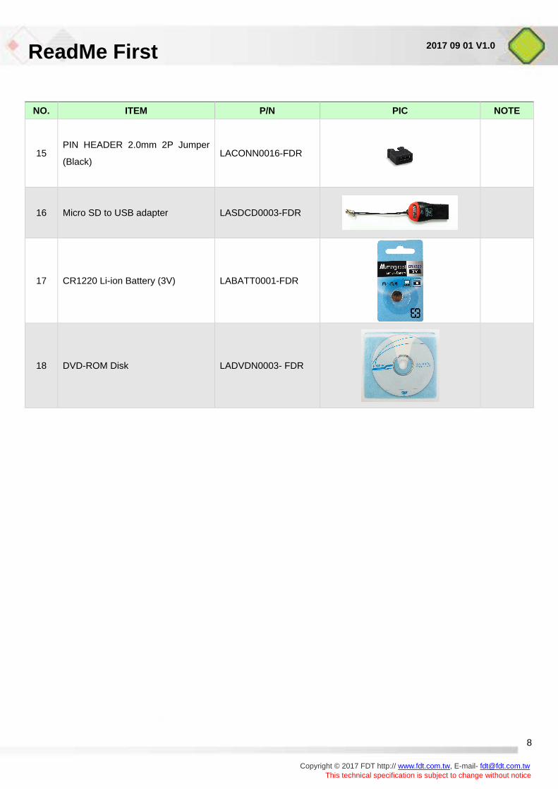
NO. ITEM P/N PIC NOTE
15 PIN HEADER 2.0mm 2P Jumper
(Black) LACONN0016-FDR
16
Micro SD to USB adapter
LASDCD0003-FDR
17 CR1220 Li-ion Battery (3V) LABATT0001-FDR
18 DVD-ROM Disk LADVDN0003- FDR
ReadMe First
Copyright © 2017 FDT http:// www.fdt.com.tw, E-mail- [email protected]
This technical specification is subject to change without notice
9
2017 09 01 V1.0
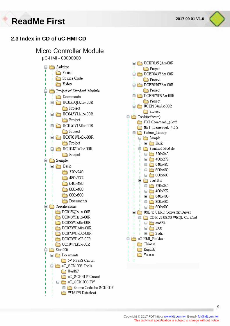
2.3 Index in CD of uC-HMI CD
ReadMe First
Copyright © 2017 FDT http:// www.fdt.com.tw, E-mail- [email protected]
This technical specification is subject to change without notice
10
2017 09 01 V1.0
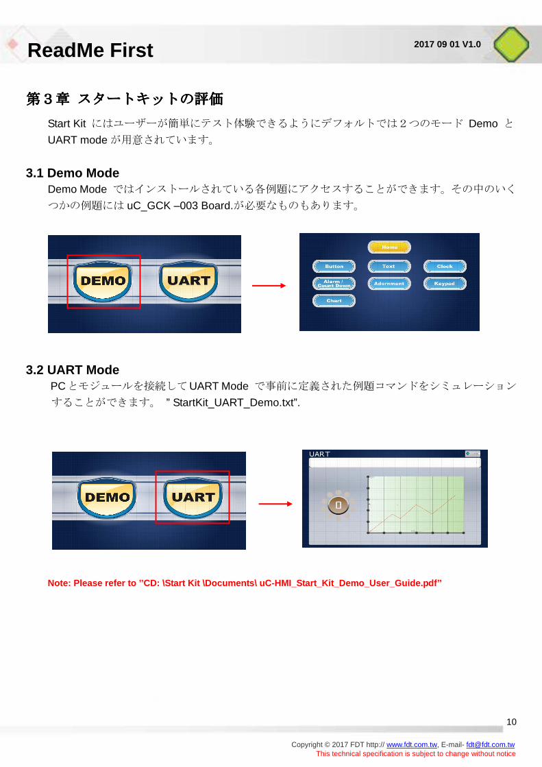
第3章第3章第3章第3章 スタートキットの評価スタートキットの評価スタートキットの評価スタートキットの評価
Start Kit にはユーザーが簡単にテスト体験できるようにデフォルトでは2つのモード Demo と
UART mode が用意されています。
3.1 Demo Mode Demo Mode ではインストールされている各例題にアクセスすることができます。その中のいく
つかの例題には uC_GCK –003 Board.が必要なものもあります。
3.2 UART Mode PCとモジュールを接続してUART Mode で事前に定義された例題コマンドをシミュレーション
することができます。 ” StartKit_UART_Demo.txt”.
Note: Please refer to ’’CD: \Start Kit \Documents\ uC-HM I_Start_Kit_Demo_User_Guide.pdf’’
ReadMe First
Copyright © 2017 FDT http:// www.fdt.com.tw, E-mail- [email protected]
This technical specification is subject to change without notice
11
2017 09 01 V1.0
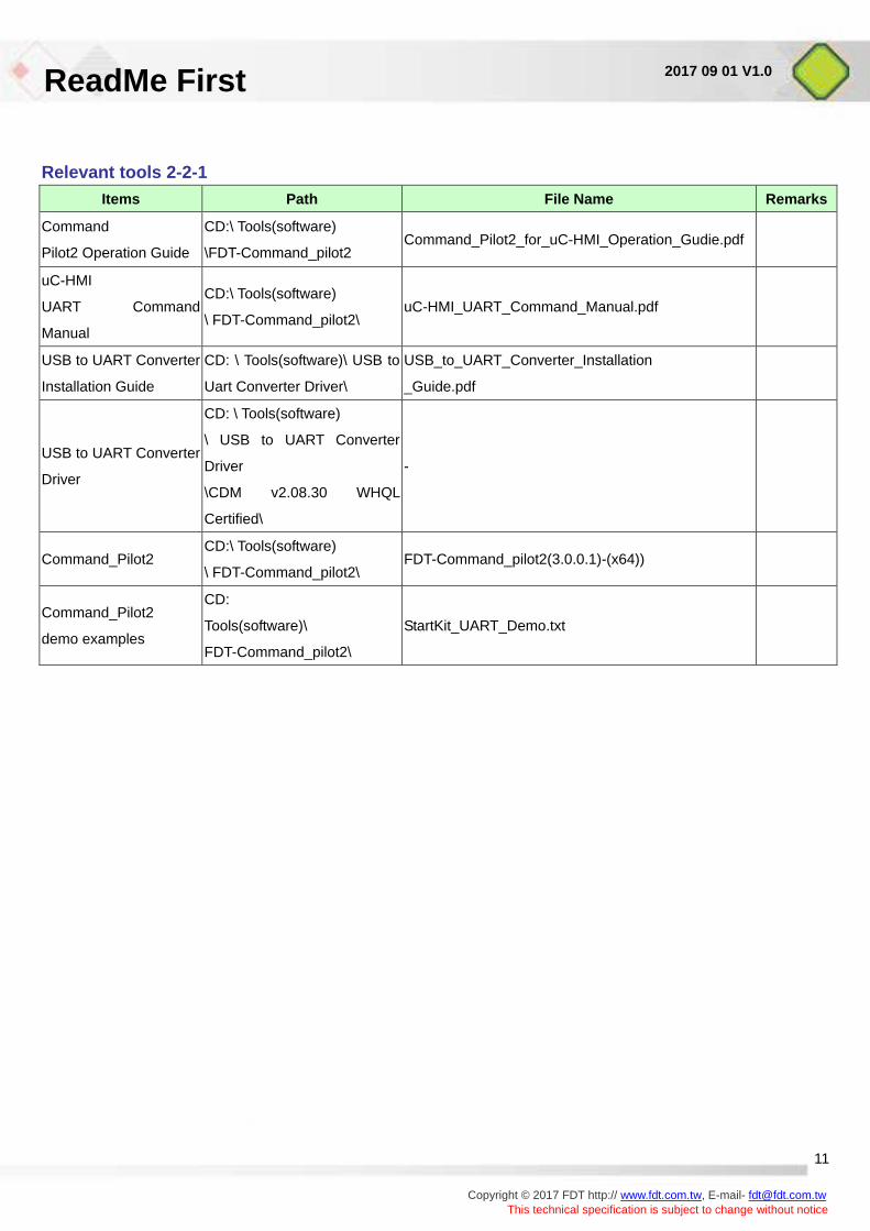
Relevant tools 2-2-1 Items Path File Name Remarks
Command
Pilot2 Operation Guide
CD:\ Tools(software)
\FDT-Command_pilot2 Command_Pilot2_for_uC-HMI_Operation_Gudie.pdf
uC-HMI
UART Command
Manual
CD:\ Tools(software)
\ FDT-Command_pilot2\ uC-HMI_UART_Command_Manual.pdf
USB to UART Converter
Installation Guide
CD: \ Tools(software)\ USB to
Uart Converter Driver\
USB_to_UART_Converter_Installation
_Guide.pdf
USB to UART Converter
Driver
CD: \ Tools(software)
\ USB to UART Converter
Driver
\CDM v2.08.30 WHQL
Certified\
-
Command_Pilot2 CD:\ Tools(software)
\ FDT-Command_pilot2\ FDT-Command_pilot2(3.0.0.1)-(x64))
Command_Pilot2
demo examples
CD:
Tools(software)\
FDT-Command_pilot2\
StartKit_UART_Demo.txt
ReadMe First
Copyright © 2017 FDT http:// www.fdt.com.tw, E-mail- [email protected]
This technical specification is subject to change without notice
12
2017 09 01 V1.0
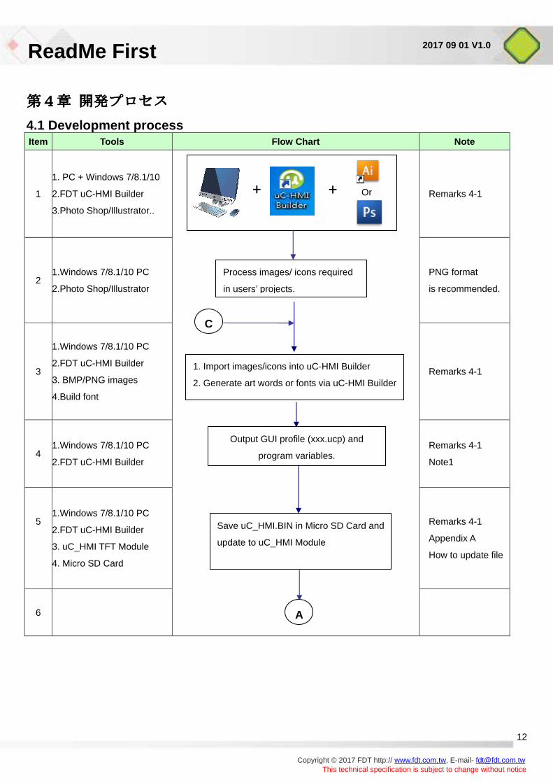
第4章第4章第4章第4章 開発プロセス開発プロセス開発プロセス開発プロセス
4.1 Development process Item Tools Flow Chart Note
1
1. PC + Windows 7/8.1/10
2.FDT uC-HMI Builder
3.Photo Shop/Illustrator..
Remarks 4-1
2 1.Windows 7/8.1/10 PC
2.Photo Shop/Illustrator
PNG format
is recommended.
3
1.Windows 7/8.1/10 PC
2.FDT uC-HMI Builder
3. BMP/PNG images
4.Build font
Remarks 4-1
4 1.Windows 7/8.1/10 PC
2.FDT uC-HMI Builder
Remarks 4-1
Note1
5
1.Windows 7/8.1/10 PC
2.FDT uC-HMI Builder
3. uC_HMI TFT Module
4. Micro SD Card
Remarks 4-1
Appendix A
How to update file
6
Save uC_HMI.BIN in Micro SD Card and
update to uC_HMI Module
Output GUI profile (xxx.ucp) and
program variables.
+
Process images/ icons required
in users’ projects.
1. Import images/icons into uC-HMI Builder
2. Generate art words or fonts via uC-HMI Builder
C
+ Or
A
ReadMe First
Copyright © 2017 FDT http:// www.fdt.com.tw, E-mail- [email protected]
This technical specification is subject to change without notice
13
2017 09 01 V1.0
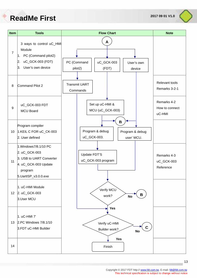
Item Tools Flow Chart Note
7
3 ways to control uC_HMI
Module
1. PC (Command pilot2)
2. uC_GCK-003 (FDT)
3. User’s own device
8 Command Pilot 2
Relevant tools
Remarks 3-2-1
9 uC_GCK-003 FDT
MCU Board
Remarks 4-2
How to connect
uC-HMI
10
Program compiler
1.KEIL C FOR uC_CK-003
2. User defined
11
1.Windows7/8.1/10 PC
2. uC_GCK-003
3. USB to UART Converter
4. uC_GCK-003 Update
program
5.UartISP_v3.0.0.exe
Remarks 4-3
uC_GCK-003
Reference
12
1. uC-HMI Module
2. uC_GCK-003
3.User MCU
13
1. uC-HMI 7'
2.PC Windows 7/8.1/10
3.FDT uC-HMI Builder
14
uC_GCK-003
(FDT)
PC (Command
pilot2) User’s own
device
Set up uC-HMI &
MCU (uC_GCK-003)
Transmit UART
Commands
A
Finish
Update FDT’S
uC_GCK-003 program
B
C
Verify MCU
work?
Verify uC-HMI
Builder work?
Yes
No
Yes
No
B
Program & debug
user’ MCU.
Program & debug
uC_GCK-003.
ReadMe First
Copyright © 2017 FDT http:// www.fdt.com.tw, E-mail- [email protected]
This technical specification is subject to change without notice
14
2017 09 01 V1.0
Remarks 4-1 Item Path File name Note
uC-HMI Builder Installation Guide CD:\ uC-HMI_Builder\ uC-HMI Builder_Installation_Guide.pdf
uC-HMI Builder user manual CD:\ uC-HMI_Builder\ uC-HMI Builder_User_Manual.pdf
uC-HMI Builder Basic Sample Guide CD: \Sample\
Basic\Documents\ uC-HMI Basic_Sample_Guide.pdf
uC-HMI Builder Basic sample CD: \ Sample\Basic\ uC-HMI_Basic_Sample.ucp
Note1. “xxx.UCP” は別のは別のは別のは別の GUI projects のためにのためにのためにのために uC-HMI Builder が作成したファイル名です。が作成したファイル名です。が作成したファイル名です。が作成したファイル名です。
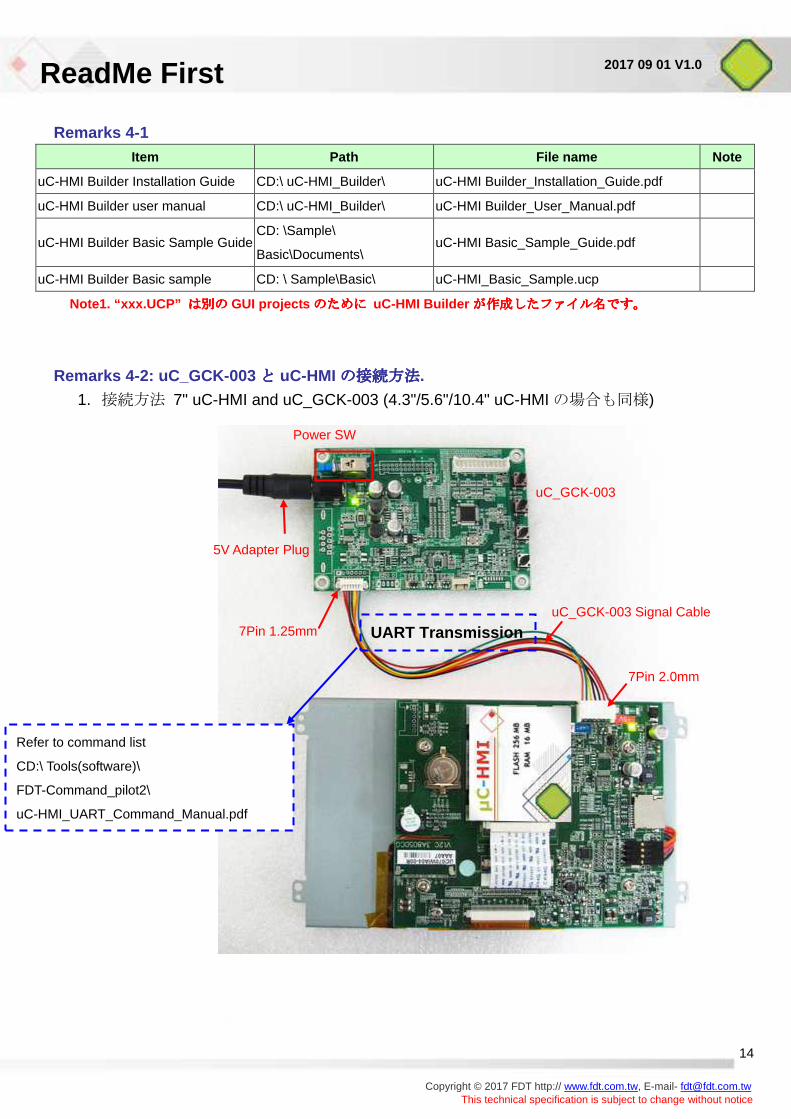
Remarks 4-2: uC_GCK-003 とととと uC-HMI の接続方法の接続方法の接続方法の接続方法.
1. 接続方法 7" uC-HMI and uC_GCK-003 (4.3"/5.6"/10.4" uC-HMI の場合も同様)
uC_GCK-003
5V Adapter Plug
7Pin 1.25mm
7Pin 2.0mm
uC_GCK-003 Signal Cable
Power SW
UART Transmission
Refer to command list
CD:\ Tools(software)\
FDT-Command_pilot2\
uC-HMI_UART_Command_Manual.pdf
ReadMe First
Copyright © 2017 FDT http:// www.fdt.com.tw, E-mail- [email protected]
This technical specification is subject to change without notice
15
2017 09 01 V1.0
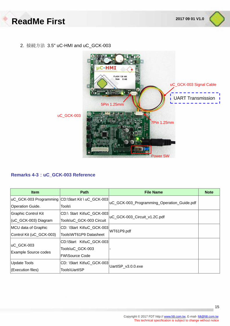
2. 接続方法 3.5" uC-HMI and uC_GCK-003
Remarks 4-3 ::::uC_GCK-003 Reference
Item Path File Name Note
uC_GCK-003 Programming
Operation Guide.
CD:\Start Kit \ uC_GCK-003
Tools\ uC_GCK-003_Programming_Operation_Guide.pdf
Graphic Control Kit
(uC_GCK-003) Diagram
CD:\ Start Kit\uC_GCK-003
Tools\uC_GCK-003 Circuit uC_GCK-003_Circuit_v1.2C.pdf
MCU data of Graphic
Control Kit (uC_GCK-003)
CD: \Start Kit\uC_GCK-003
Tools\WT61P9 Datasheet WT61P9.pdf
uC_GCK-003
Example Source codes
CD:\Start Kit\uC_GCK-003
Tools\uC_GCK-003
FW\Source Code
-
Update Tools
(Execution files)
CD: \Start Kit\uC_GCK-003
Tools\UartISP UartISP_v3.0.0.exe
uC_GCK-003
uC_GCK-003 Signal Cable
5Pin 1.25mm
7Pin 1.25mm
Power SW
UART Transmission
ReadMe First
16 Copyright © 2017 FDT http:// www.fdt.com.tw, E-mail- [email protected]
This technical specification is subject to change without notice
2017 09 01 V1.0
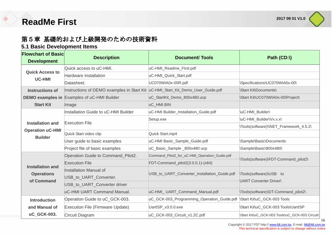
第5章第5章第5章第5章 基礎的および上級開発のための技術資料基礎的および上級開発のための技術資料基礎的および上級開発のための技術資料基礎的および上級開発のための技術資料 5.1 Basic Development Items Flowchart of Basic
Development Description Document/ Tools Path (CD:\)
Quick Access to
UC-HMI
Quick access to uC-HMI. uC-HMI_Readme_First.pdf
Hardware Installation uC-HMI_Quick_Start.pdf
Datasheet. UC070WIA0x-00R.pdf \Specifications\UC070WIA0x-00\
Instructions of
DEMO examples in
Start Kit
Instructions of DEMO examples in Start Kit uC-HMI_Start_Kit_Demo_User_Guide.pdf \Start Kit\Documents\
Examples of uC-HMI Builder uC_StartKit_Demo_800x480.ucp \Start Kit\UC070WIA0x-00\Project\
Image uC_HMI.BIN
Installation and
Operation uC-HMI
Builder
Installation Guide to uC-HMI Builder uC-HMI Builder_Installation_Guide.pdf \uC-HMI_Builder\
Execution File Setup.exe \uC-HMI_Builder\Vx.x.x\
\Tools(software)\\NET_Framework_4.5.2\
Quick Start video clip Quick Start.mp4
User guide to basic examples uC-HMI Basic_Sample_Guide.pdf \Sample\Basic\Documents
Project file of basic examples uC_Basic_Sample _800x480 ucp \Sample\Basic\800x480\
Installation and
Operations
of Command
Operation Guide to Command_Pilot2. Command_Pilot2_for_uC-HMI_Operation_Gudie.pdf \Tools(software)\FDT-Command_pilot2\
Execution File FDT-Command_pilot2(3.0.0.1)-(x64)
Installation Manual of
USB_to_UART_Converter. USB_to_UART_Converter_Installation_Guide.pdf \Tools(software)\USB to
UART Converter Driver\ USB_to_UART_Converter driver
uC-HMI UART Command Manual. uC-HMI_ UART_Command_Manual.pdf \Tools(software)\DT-Command_pilot2\
Introduction
and Manual of
uC_GCK-003.
Operation Guide to uC_GCK-003. uC_GCK-003_Programming_Operation_Guide.pdf \Start Kit\uC_GCK-003 Tools
Execution File (Firmware Update) UartISP_v3.0.0.exe \Start Kit\uC_GCK-003 Tools\UartISP
Circuit Diagram uC_GCK-003_Circuit_v1.2C.pdf \Start Kit\uC_GCK-003 Tools\uC_GCK-003 Circuit\
ReadMe First
17 Copyright © 2017 FDT http:// www.fdt.com.tw, E-mail- [email protected]
This technical specification is subject to change without notice
2017 09 01 V1.0
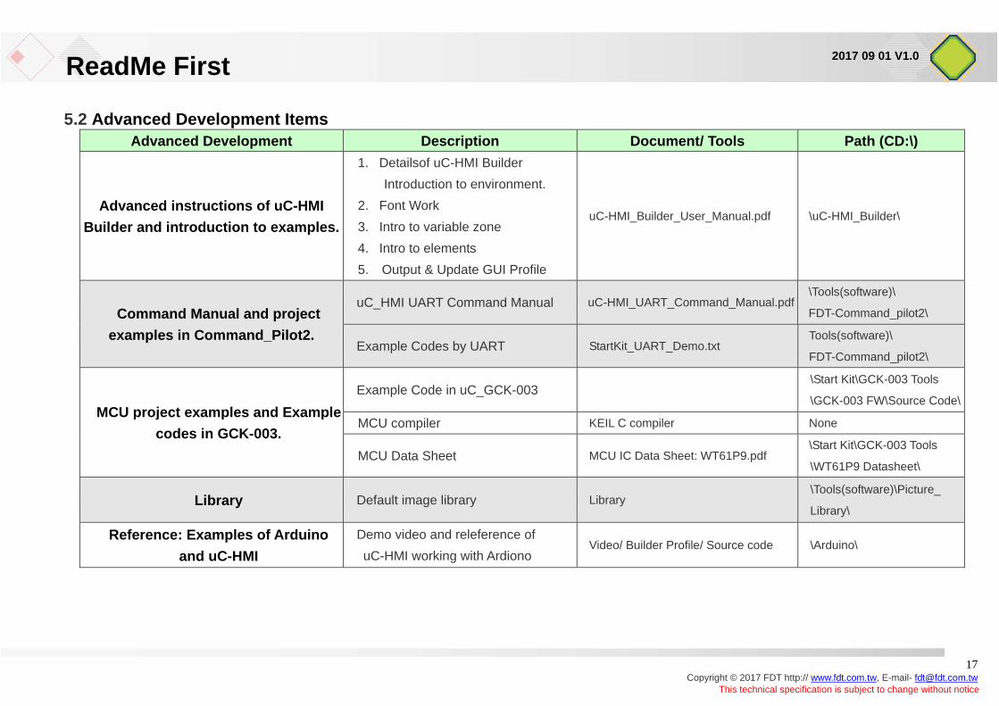
5.2 Advanced Development Items Advanced Development Description Document/ Tools Path (CD:\)
Advanced instructions of uC-HMI
Builder and introduction to examples.
1. Detailsof uC-HMI Builder
Introduction to environment.
2. Font Work
3. Intro to variable zone
4. Intro to elements
5. Output & Update GUI Profile
uC-HMI_Builder_User_Manual.pdf \uC-HMI_Builder\
Command Manual and project
examples in Command_Pilot2.
uC_HMI UART Command Manual uC-HMI_UART_Command_Manual.pdf \Tools(software)\
FDT-Command_pilot2\
Example Codes by UART StartKit_UART_Demo.txt Tools(software)\
FDT-Command_pilot2\
MCU project examples and Example
codes in GCK-003.
Example Code in uC_GCK-003 \Start Kit\GCK-003 Tools
\GCK-003 FW\Source Code\
MCU compiler KEIL C compiler None
MCU Data Sheet MCU IC Data Sheet: WT61P9.pdf \Start Kit\GCK-003 Tools
\WT61P9 Datasheet\
Library Default image library Library \Tools(software)\Picture_
Library\
Reference: Examples of Arduino
and uC-HMI
Demo video and releference of
uC-HMI working with Ardiono Video/ Builder Profile/ Source code \Arduino\
ReadMe First
18 Copyright © 2017 FDT http:// www.fdt.com.tw, E-mail- [email protected]
This technical specification is subject to change without notice
2017 09 01 V1.0
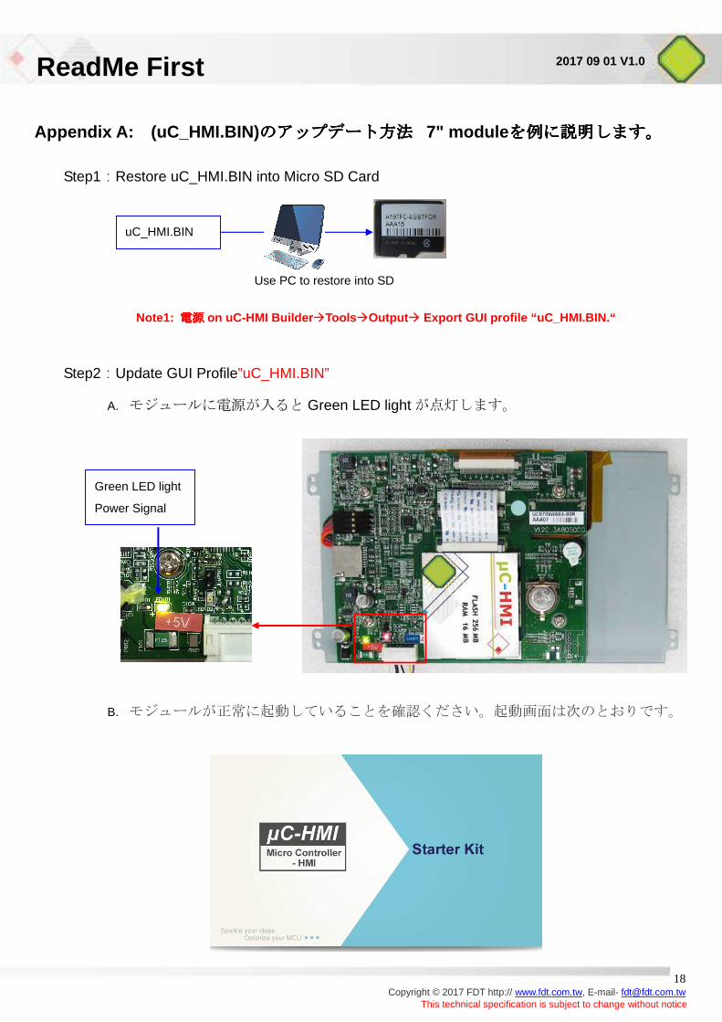
Appendix A: (uC_HMI.BIN) のアップデート方法のアップデート方法のアップデート方法のアップデート方法 7" module を例に説明します。を例に説明します。を例に説明します。を例に説明します。
Step1:Restore uC_HMI.BIN into Micro SD Card
Note1: 電源電源電源電源 on uC-HMI Builder Tools Output Export GUI profile “uC_HMI.BIN.“
Step2:Update GUI Profile”uC_HMI.BIN”
A. モジュールに電源が入ると Green LED light が点灯します。
B. モジュールが正常に起動していることを確認ください。起動画面は次のとおりです。
uC_HMI.BIN
Use PC to restore into SD
Green LED light
Power Signal
ReadMe First
19 Copyright © 2017 FDT http:// www.fdt.com.tw, E-mail- [email protected]
This technical specification is subject to change without notice
2017 09 01 V1.0
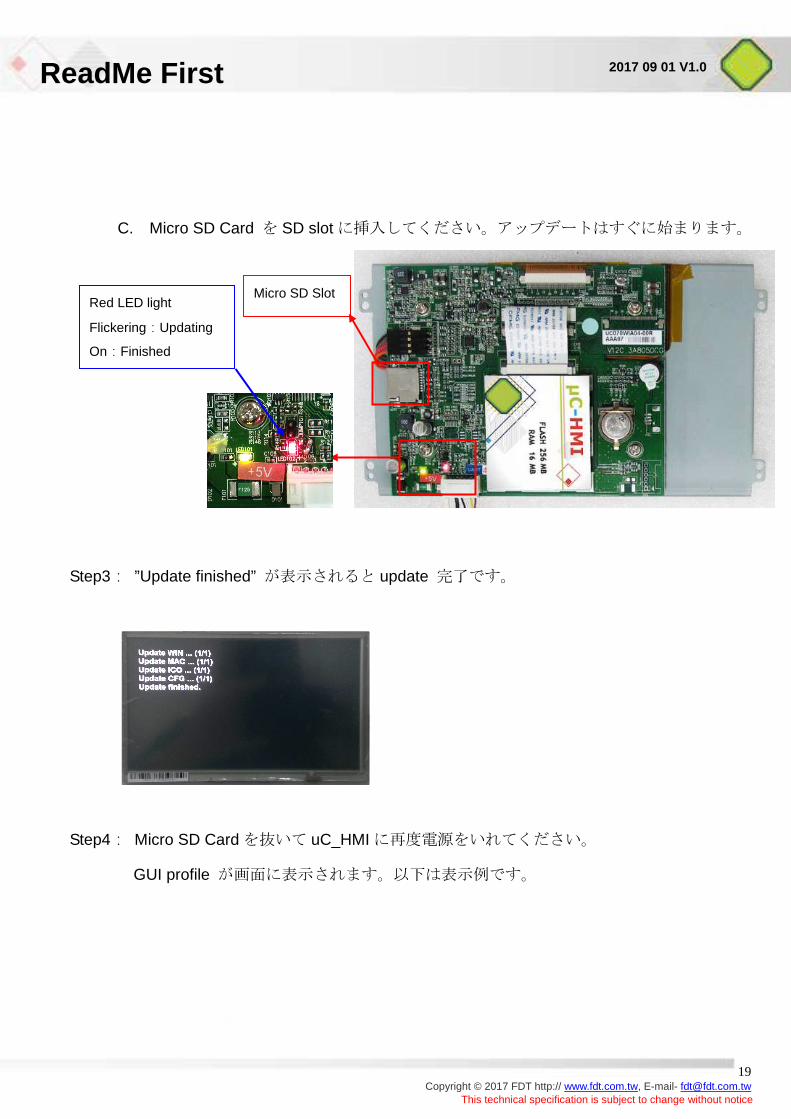
C. Micro SD Card を SD slot に挿入してください。アップデートはすぐに始まります。
Step3: ”Update finished” が表示されると update 完了です。
Step4: Micro SD Card を抜いて uC_HMI に再度電源をいれてください。
GUI profile が画面に表示されます。以下は表示例です。
Red LED light
Flickering:Updating
On:Finished
Micro SD Slot
ReadMe First
20 Copyright © 2017 FDT http:// www.fdt.com.tw, E-mail- [email protected]
This technical specification is subject to change without notice
2017 09 01 V1.0
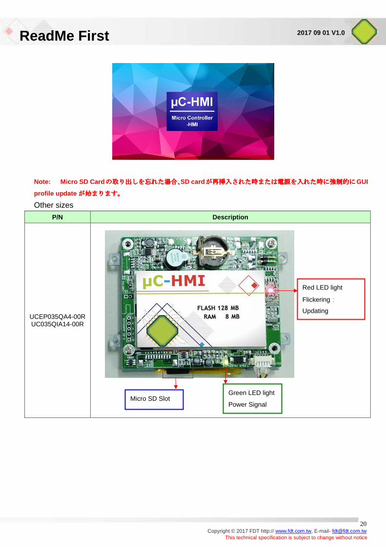
Note: Micro SD Card のののの取り出取り出取り出取り出ししししをををを忘忘忘忘れれれれたたたた場合場合場合場合、、、、SD card が再挿入された時または電源を入れた時に強制的にが再挿入された時または電源を入れた時に強制的にが再挿入された時または電源を入れた時に強制的にが再挿入された時または電源を入れた時に強制的にGUI
profile update が始まります。が始まります。が始まります。が始まります。
Other sizes
P/N Description
UCEP035QA4-00R UC035QIA14-00R
Green LED light
Power Signal Micro SD Slot
Red LED light
Flickering:
Updating
ReadMe First
21 Copyright © 2017 FDT http:// www.fdt.com.tw, E-mail- [email protected]
This technical specification is subject to change without notice
2017 09 01 V1.0
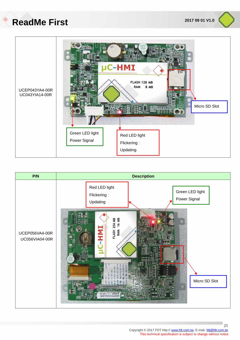
UCEP043YA4-00R UC043YIA14-00R
P/N Description
UCEP056VA4-00R
UC056VIA04-00R
Micro SD Slot
Red LED light
Flickering:
Updating
Green LED light
Power Signal
Green LED light
Power Signal
Red LED light
Flickering:
Updating
Micro SD Slot
ReadMe First
22 Copyright © 2017 FDT http:// www.fdt.com.tw, E-mail- [email protected]
This technical specification is subject to change without notice
2017 09 01 V1.0
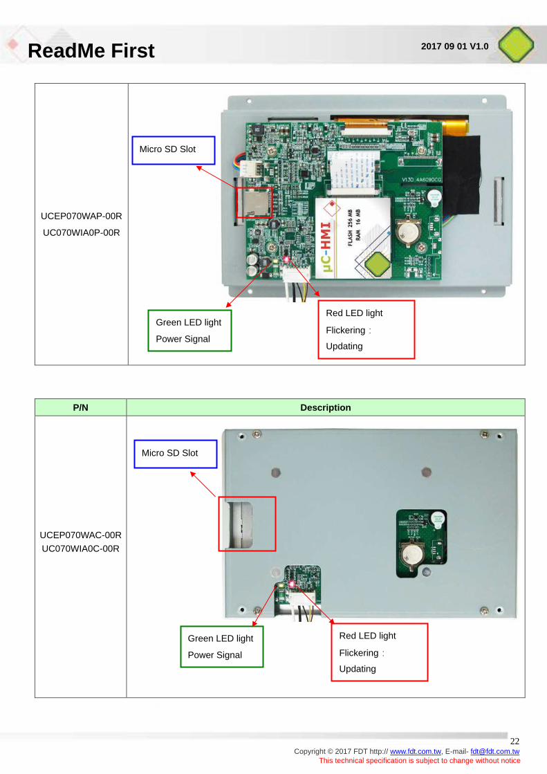
UCEP070WAP-00R
UC070WIA0P-00R
P/N Description
UCEP070WAC-00R UC070WIA0C-00R
Micro SD Slot
Red LED light
Flickering:
Updating
Green LED light
Power Signal
Green LED light
Power Signal
Red LED light
Flickering:
Updating
Micro SD Slot
ReadMe First
23 Copyright © 2017 FDT http:// www.fdt.com.tw, E-mail- [email protected]
This technical specification is subject to change without notice
2017 09 01 V1.0
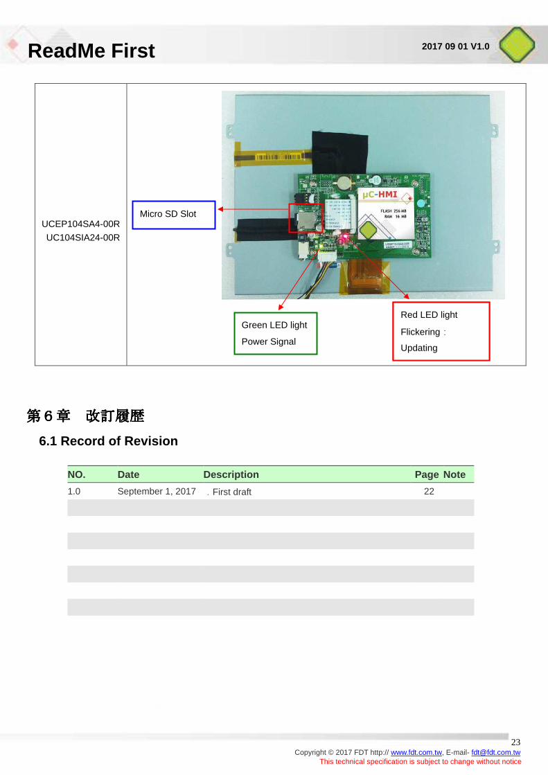
UCEP104SA4-00R
UC104SIA24-00R
第6章第6章第6章第6章 改訂履歴改訂履歴改訂履歴改訂履歴
6.1 Record of Revision
NO. Date Description Page Note
1.0 September 1, 2017 .First draft 22
Micro SD Slot
Green LED light
Power Signal
Red LED light
Flickering:
Updating
ReadMe First
24 Copyright © 2017 FDT http:// www.fdt.com.tw, E-mail- [email protected]
This technical specification is subject to change without notice
2017 09 01 V1.0
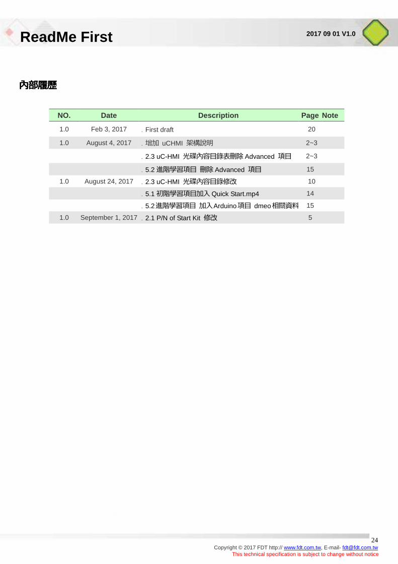
內內內內內內內內內內內內內內內內
NO. Date Description Page Note
1.0 Feb 3, 2017 .First draft 20
1.0 August 4, 2017 .增增 uCHMI 架架架架 2~3
.2.3 uC-HMI 光光光光光光光光光 Advanced 項光 2~3
.5.2 進進進進項光 光光Advanced 項光 15
1.0 August 24, 2017 .2.3 uC-HMI 光光光光光光光光 10
.5.1 初進進進項光增初 Quick Start.mp4 14
.5.2進進進進項光 增初Arduino項光 dmeo相相相相 15
1.0 September 1, 2017 .2.1 P/N of Start Kit 光光 5