a9k kaba repeater
TRANSCRIPT
7/31/2019 A9k KABA Repeater
http://slidepdf.com/reader/full/a9k-kaba-repeater 1/8
A9k-501_Simple_Repeater_V103.doc Rev 1.03 2003-10-21 Page 1 of 1
SRM9000-Application Note A9k-501
SIMPLEST BACK-TO-BACK RADIO REPEATER Applicable to models:
9005
General
The purpose of back-to-back Transceivers is to allow signals received on one radio to beretransmitted on a second radio - either as a link (dedicated Receiver connected to
dedicated Transmitter) or as a bidirectional Repeater (either radio can act as Receiver and/or Transmitter).
This Application Note describes the simplest repeater configuration possible.
Repeater
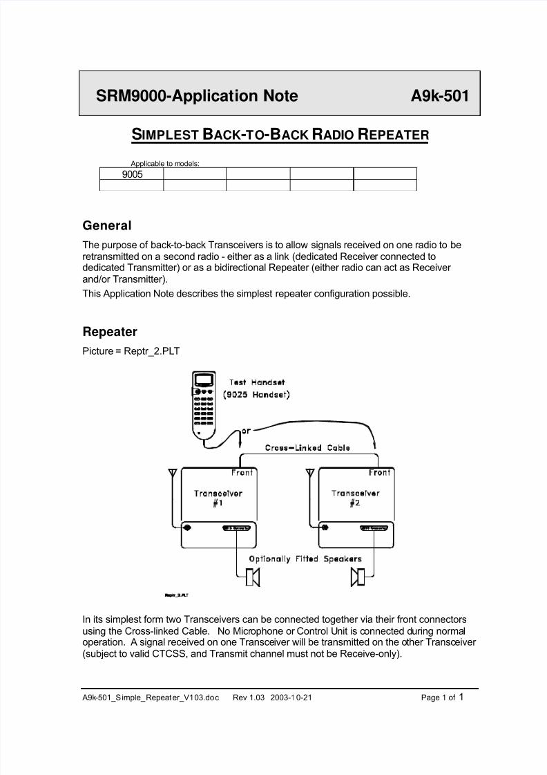
Picture = Reptr_2.PLT
In its simplest form two Transceivers can be connected together via their front connectorsusing the Cross-linked Cable. No Microphone or Control Unit is connected during normaloperation. A signal received on one Transceiver will be transmitted on the other Transceiver (subject to valid CTCSS, and Transmit channel must not be Receive-only).
7/31/2019 A9k KABA Repeater
http://slidepdf.com/reader/full/a9k-kaba-repeater 2/8
A9k-501_Simple_Repeater_V103.doc Rev 1.03 2003-10-21 Page 2 of 2
On each radio, the channel can be selected by unplugging the Cross-linked Cable andplugging in a SRM9025 Handset unit. With the Handset connected :
◊ The operating channel can be selected.◊ The channel can be checked for acceptable reception by using the Handset to Receive
and Transmit on the selected channel.
◊ The Repeater audio level can be adjusted (Nominal Volume level of ‘15’).The Handset should be unplugged while the radio is still switched ON. This will leave theradio in the ON state. Settings selected by the Handset are permanently retained in FLASHwhen the Handset is removed.
The received signal will sound through the optional Loudspeaker. Note the Loudspeaker volume level is fixed by the setting selected as the output level for the other Transceiver.
Setting a Volume Level of ‘15’ (using the Test Handset connected to the receiving radio)will result in a repeater gain of approximately unity.
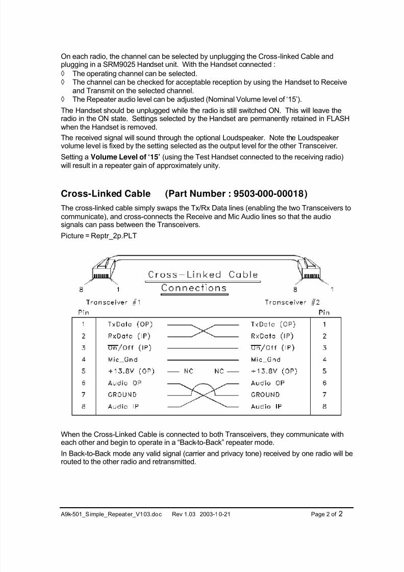
Cross-Linked Cable (Part Number : 9503-000-00018)
The cross-linked cable simply swaps the Tx/Rx Data lines (enabling the two Transceivers tocommunicate), and cross-connects the Receive and Mic Audio lines so that the audiosignals can pass between the Transceivers.
Picture = Reptr_2p.PLT
When the Cross-Linked Cable is connected to both Transceivers, they communicate witheach other and begin to operate in a “Back-to-Back” repeater mode.
In Back-to-Back mode any valid signal (carrier and privacy tone) received by one radio will berouted to the other radio and retransmitted.
7/31/2019 A9k KABA Repeater
http://slidepdf.com/reader/full/a9k-kaba-repeater 3/8
A9k-501_Simple_Repeater_V103.doc Rev 1.03 2003-10-21 Page 3 of 3
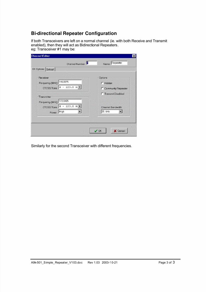
Bi-directional Repeater Configuration
If both Transceivers are left on a normal channel (ie. with both Receive and Transmitenabled), then they will act as Bidirectional Repeaters.
eg: Transceiver #1 may be:
Similarly for the second Transceiver with different frequencies.
7/31/2019 A9k KABA Repeater
http://slidepdf.com/reader/full/a9k-kaba-repeater 4/8
A9k-501_Simple_Repeater_V103.doc Rev 1.03 2003-10-21 Page 4 of 4
Link Configuration
Links can be set up in various configurations, depending on the channels selected on eachTransceiver. eg:
Transceiver #1 Transceiver #2 CommentRx-Only Channel Tx-Only Channel Rx on #1, Tx on #2
Rx-Only Channel Normal Channel Rx on #1, Tx on #2
Normal Channel Tx-Only Channel Rx on #1, Tx on #2
Normal Channel Normal Channel Bi-directional Repeater (see above)
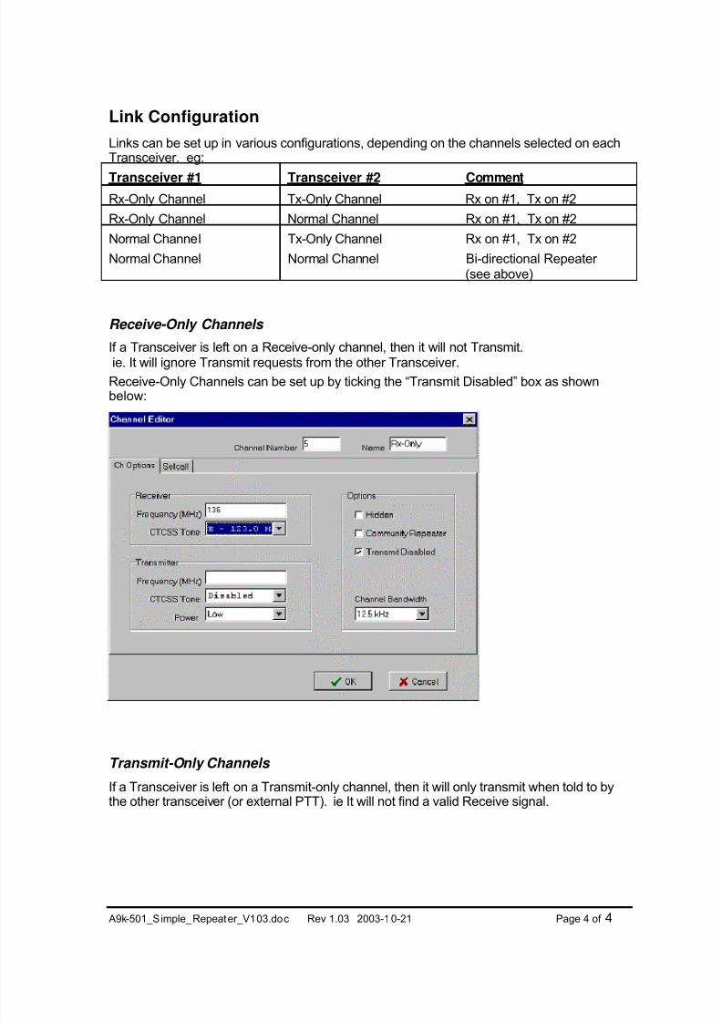
Receive-Only Channels
If a Transceiver is left on a Receive-only channel, then it will not Transmit.
ie. It will ignore Transmit requests from the other Transceiver.
Receive-Only Channels can be set up by ticking the “Transmit Disabled” box as shownbelow:
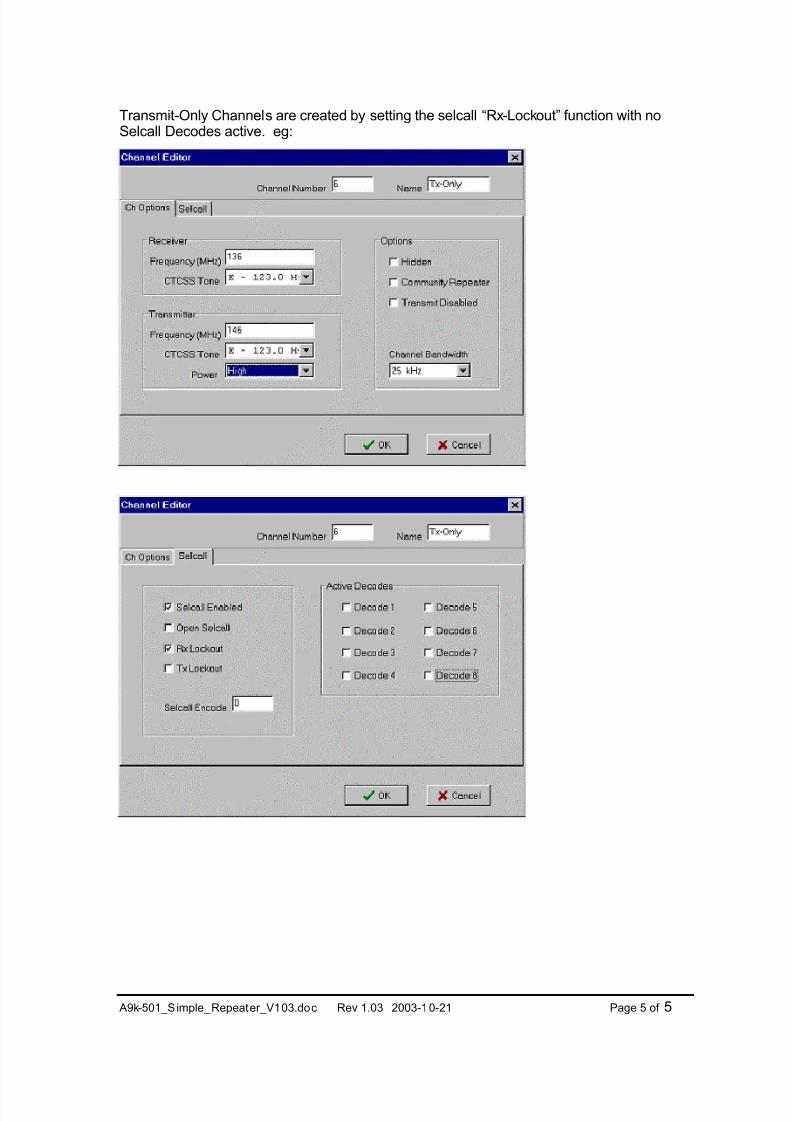
Transmit-Only Channels
If a Transceiver is left on a Transmit-only channel, then it will only transmit when told to bythe other transceiver (or external PTT). ie It will not find a valid Receive signal.
7/31/2019 A9k KABA Repeater
http://slidepdf.com/reader/full/a9k-kaba-repeater 5/8
A9k-501_Simple_Repeater_V103.doc Rev 1.03 2003-10-21 Page 5 of 5
Transmit-Only Channels are created by setting the selcall “Rx-Lockout” function with noSelcall Decodes active. eg:
7/31/2019 A9k KABA Repeater
http://slidepdf.com/reader/full/a9k-kaba-repeater 6/8
A9k-501_Simple_Repeater_V103.doc Rev 1.03 2003-10-21 Page 6 of 6
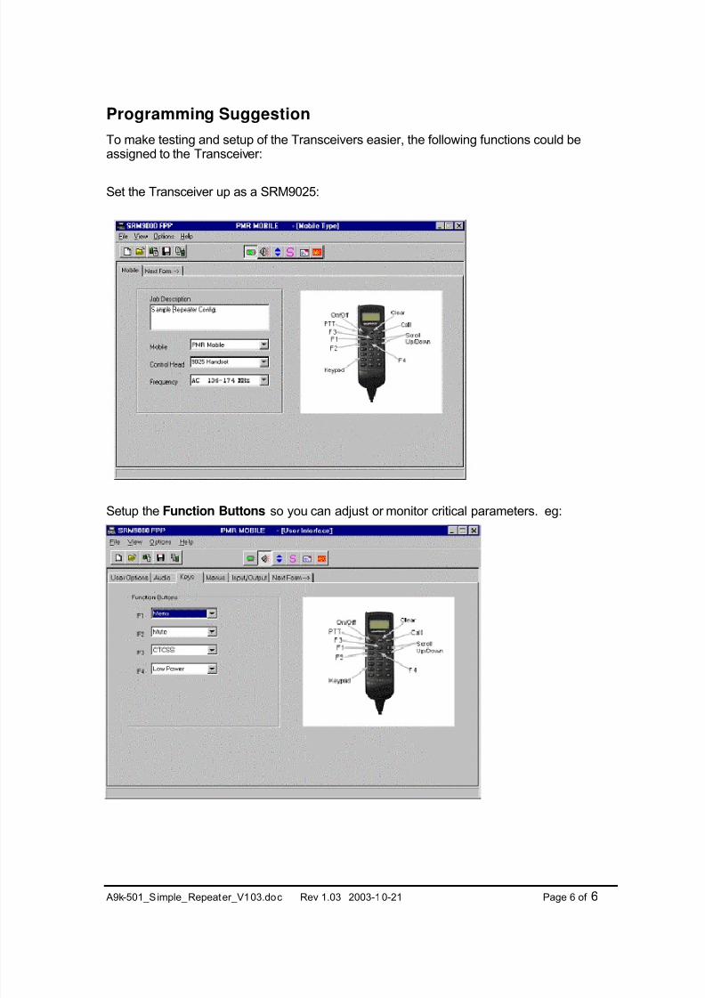
Programming Suggestion
To make testing and setup of the Transceivers easier, the following functions could beassigned to the Transceiver:
Set the Transceiver up as a SRM9025:
Setup the Function Buttons so you can adjust or monitor critical parameters. eg:
7/31/2019 A9k KABA Repeater
http://slidepdf.com/reader/full/a9k-kaba-repeater 7/8
A9k-501_Simple_Repeater_V103.doc Rev 1.03 2003-10-21 Page 7 of 7
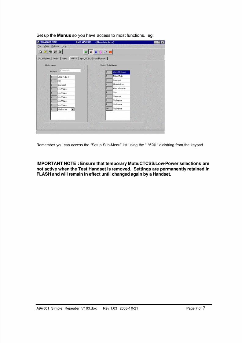
Set up the Menus so you have access to most functions. eg:
Remember you can access the “Setup Sub-Menu” list using the “ *52# “ dialstring from the keypad.
IMPORTANT NOTE : Ensure that temporary Mute/CTCSS/Low-Power selections are
not active when the Test Handset is removed. Settings are permanently retained inFLASH and will remain in effect until changed again by a Handset.
7/31/2019 A9k KABA Repeater
http://slidepdf.com/reader/full/a9k-kaba-repeater 8/8
A9k-501_Simple_Repeater_V103.doc Rev 1.03 2003-10-21 Page 8 of 8
Local Indicators and Alarms
Receive or Transmit Indication
The DB15-Connector Output0 line (Pin 8) can be programmed to switch when certainevents occur. eg:
• Low when Carrier detected
• Low when Valid Signal (Carrier + CTCSS) detected
• Low when Transmitting
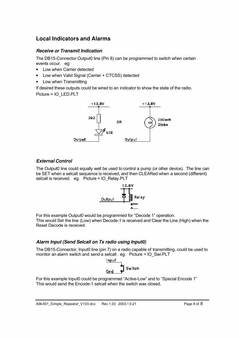
If desired these outputs could be wired to an indicator to show the state of the radio.
Picture = IO_LED.PLT
External Control
The Output0 line could equally well be used to control a pump (or other device). The line canbe SET when a selcall sequence is received, and then CLEARed when a second (different)
selcall is received. eg. Picture = IO_Relay.PLT
For this example Output0 would be programmed for “Decode 1” operation.This would Set the line (Low) when Decode-1 is received and Clear the Line (High) when theReset Decode is received.
Alarm Input (Send Selcall on Tx radio using Input0)
The DB15-Connector, Input0 line (pin 7) on a radio capable of transmitting, could be used tomonitor an alarm switch and send a selcall . eg. Picture = IO_Swi.PLT
For this example Input0 could be programmed “Active-Low” and to “Special Encode 1”This would send the Encode-1 selcall when the switch was closed.