電信工程研究所 - ir.nctu.edu.tw ·...
TRANSCRIPT

國 立 交 通 大 學
電信工程研究所
碩 士 論 文
正交頻率多工訊號之峰均值降低之研究
Studies of Peak-to-Average Power Ratio Reduction for OFDM Signals
研 究 生董原豪
指導教授蘇育德 教授
中 華 民 國 九 十 九 年 七 月
正交頻率多工訊號之峰均值降低之研究
Studies of Peak-to-Average Power Ratio Reduction for OFDM Signals
研 究 生董原豪 StudentYuan-Hao Tung
指導教授蘇育德 AdvisorDr Yu T Su
國 立 交 通 大 學
電 信 工 程 研 究 所
碩 士 論 文
A Thesis
Submitted to Institute of Communication Engineering
College of Electrical and computer Engineering
National Chiao Tung University
in partial Fulfillment of the Requirements
for the Degree of
Master of science
in
Communication Engineering
July 2010
Hsinchu Taiwan Republic of China
中華民國九十九年七月
i
正交頻率多工訊號之峰均值降低之研究
學生董原豪 指導教授蘇育德 博士
國立交通大學電信工程研究所碩士班
摘 要
正交頻率多工(OFDM)系統可提供高資料傳輸量但此系統會使時間訊號產生高峰均
值(PAPR)的現象而在這篇論文當中我們主要使用兩種方法一種為裁剪法(Clipping)
一種為選擇性映射(Selective Mapping)
傳統裁剪法針對時間訊號的振幅做裁剪而我們提出的裁剪法針對時間訊號實部跟虛
部分開來裁剪而在頻譜我們採用多種約束區域(Constraint set)像是有界區域
(Bounded Region)主動式星座圖延展(Active Constellation Extension)保留載波
(Tone Reservation)接著我們將整個問題公式化成線性規畫型式再由已發展完善的
線性規畫工具解出最佳被裁減的傳輸訊號
另外在探討選擇性映射時會討論到旁解碼訊號(side information)的傳送通
常做法有兩種我們個別對這兩種做法提出解決辦法第一種是設計選擇性映射序列
(Selective mapping sequences)使得傳送端不用傳送旁解碼訊號而接收機直接借
由判斷接收訊號的特徵判斷選擇性映射序列而提出的設計能夠達到降低接收端偵測選
擇性映射序列特徵(side information)的錯誤率且同時維持此序列的降低峰均值能力
因為此序列的產生可以由群論找到極為簡單耗費的記憶體也極少的方法因此有實作
上的貢獻我們提出的另外一種方法是將旁解碼訊號插入同一個被傳送的OFDM Symbol
並且藉由調整旁解碼訊號的頻域訊號點而達到進一步降低峰均值以及降低旁解碼訊號
偵測的錯誤率
ii
Studies of Peak-to-Average Power Ratio Reduction
for OFDM Signals Student Yuan-Hao Tung Advisor Yu T Su
Institute of Communications Engineering
National Chiao Tung University
Abstract
In this thesis we propose several approaches for reducing peak-to-average power ratio (PAPR) of orthogonal
frequency division multiplexing (OFDM) signals
The conventional clipping approach clips the magnitude of a time-domain OFDM waveform while leaving its
phase intact We present a novel time-domain clipping method with hybrid frequency domain constraint by
independently clipping both real and imaginary parts of a complex time-domain OFDM waveform and using
linear programming (LP) to obtain the optimal clipped signal
Selective mapping (SLM) often requires that side information about the mapping sequence used be sent along
with the desired data sequence Maximum likelihood detection without side information is realized at the cost of
much higher complexity We proposed a novel SLM sequences design which enable a receiver to use a simple
detector without side information leading to bandwidth efficiency and capacity improvement The proposed
design also has the advantages of simple encoding implementation and low memory requirement
When SLM side information is needed for signal detection it is often protected with a low rate forward
error-correcting code We propose an SLM scheme with embedded side information Active constellation
extension (ACE) and projection onto convex set (POCS) techniques are used to adjust side information for both
reducing PAPR and achieving better SLM index detection probability
iii
誌 謝
人生的第一個求學階段(小學國中高中大學研究所)在交通大學電信工程
研究所做一個總結感謝學校和系上給予的所有資源不僅讓我在書本中開眼界也能
到美國嘗試交換學生的經驗讓我的求學生涯與眾不同在許許多多要感謝的教授當中
我特別感謝我的指導教授蘇育德博士因為他的指導我的論文才能夠這麼順利的完成
除了專業知識外在碩士班每周一次的報告當中加入實驗室成員的生活經驗分享並且
分享老師個人的人生經驗讓我在做人處事方面能夠更加成熟更加全面 我還要感謝實驗室的林坤昌學長在我大學部專題以及碩士班兩年在研究方面
指導我給予我很多很好的建議觀念與經驗分享幫助我的論文完成除了研究之外
平常跟學長日常生活相處當中也獲得不少做人處事的觀念及態度另外也感謝實驗室所
有的學長姐(博士班的學長們96 級的碩班學長姐)給予的指導感謝實驗室 97 級同學這
兩年一起同甘共苦以及 98 級學弟妹這一年的陪伴希望大家在之後人生的路上都順
遂還要再感謝實驗室的助理(淑琪姐昱岑姐)幫忙實驗室處理大大小小的事情幫
忙我處理去國外會議的報帳問題謝謝你們 感謝我的家人一直以來不求回報的付出並且在生活跟心靈上的支持讓我
無後顧之憂的往前衝刺往目標邁進今天我以我很棒的家庭為榮希望之後我的家人們
能以我為榮 最後感謝每一個幫助過我的人一起揮灑過汗水的夥伴一起歡笑的朋友
感謝你
董原豪謹誌 于新竹國立交通大學
Contents
Contents iv
List of Figures vi
List of Tables ix
1 Introduction 1
2 Orthogonal Frequency Division Multiplexing and Peak-to-Average Power
Ratio 5
3 Non-linear clipping with hybrid frequency domain constraints 10
31 Background 10
32 PAPR and Available Subcarriers in OFDM Systems 11
33 Nonlinear Clipping as an Optimization Problem 12
331 Clipping as Multiple Constraints 13
332 Bounded Constellation Errors 15
34 Simulation Results 18
35 Chapter Summary 23
4 Selective Mapping without Side Information 24
41 Background 24
42 System Model 25
43 Sequence design criteria 29
iv
44 A Review on Group Theory 30
45 Proposed SLM Sequence Design 31
46 Low Complexity SLM Encoder 35
47 Simulation Results 37
48 Chapter Summary 42
5 Selective Mapping with Embedded Side Information 43
51 System Model 43
52 Encoding Side Information and Insertion 45
521 Insertion of the Side Information 45
522 Estimation of Side Information 45
523 Encoding Scheme of SI 46
53 Side Information Adjustment Algorithm 47
531 Problem Formulation 47
532 Active Constellation Extension for SI Adjustment 48
533 Projection onto Complex Set for SI Adjustment 51
54 Numerical Results 53
55 Chapter Summary 56
6 Conclusion 58
61 Summary of Contributions 58
62 Some Future Works 59
Bibliography 63
v
List of Figures
21 Block diagram of OFDM system 5
22 Bandwidth utilization of OFDM system 6
23 Time domain signal of a 16-channel OFDM signal modulated with the
same phase for all sub-channels 7
24 inputoutput characteristic curve of a power amplifier 8
31 Conventional clipping block diagram 10
32 Block diagram of proposed clipping approach 11
33 The time domain clipping rule 13
34 Constellation error constraints for 16-QAM Those colored area of internal
points are bounded region and those for external points are extended region 15
35 Original time-domain signal with PAPR=96448 dB 19
36 Clipped time-domain signal with PAPR=59015 dB 20
37 Constellation of distorted frequency-domain signal achieving 37433 dB
PAPR reduction 20
38 Phase difference and amplitude trajectories of a typical time-domain se-
quence before and after nonlinear clipping 21
39 Effective PAPR gain for 16-QAM 256-carrier OFDM symbol with L=4
over-sampling for δ = 005dmin δ = 01dmin ACE RCFBD and sepa-
rated coordinate PAPR 22
310 BER of a 16-QAM and 256-carrier OFDM system 22
vi
41 Original SLM encoder 25
42 SLM decoder proposed by Tellambura and Jayalath in [10] 26
43 Distribution of generated element gk on unit circle 33
44 Block diagram of low complexity SLM encoder 35
45 Block diagram of modified low complexity SLM encoder 37
46 CCDF plot of PAPR performance of random sequences chaotic sequences
and proposed sequences design 38
47 Probability of sequence index detection failure under frequency selective
channel 39
48 Euclidean distance of random sequences chaotic sequences and proposed
sequence design 39
49 Probability of sequence index detection failure of proposed sequences and
Alsusa and Yang sequences under frequency selective channel 40
410 CCDF of PAPR performance of original OFDM symbol low complexity
SLM encoder and original SLM 40
51 Bandwidth utilization of proposed scheme 43
52 Original SLM encoder with embedded SI 44
53 Extended region of QPSK denoted as F 48
54 Amplitude modulation for POCS algorithm 51
55 Location of modified SI symbol using active constellation extension (ACE)
algorithm 54
56 Location of modified SI symbol using projection onto complex set (POCS)
algorithm 54
57 Key error rate for ACE and POCS schemes 55
58 CCDF of PAPR of original SLM SLM embedded SI and SLM with mod-
ified SI (ACE) 55
vii
59 CCDF of PAPR of original SLM SLM embedded SI and SLM with mod-
ified SI (POCS) 56
viii
List of Tables
51 Active constellation extension with smart gradient projection algorithm 50
52 Projection onto Complex Set algorithm 52
ix
Chapter 1
Introduction
Recent developments in digital content have made the demand on video stream from
youtube and editing documents through a remote server basic functional requirements for
an intelligent portable handset Orthogonal frequency division multiplexing (OFDM)
is a well known technique for high mobility wireless transmissions It modulates de-
multiplexed data streams on a large number of orthogonal sub-carriers with minimum
spacing converting a wideband waveform into parallel narrowband signals The primary
advantage of OFDM over single-carrier schemes is its ability to cope with severe channel
conditions without the need of complex equalization
However OFDM waveforms often have high amplitude fluctuations and result in
large peak-to-average power ratio (PAPR) As the digital-to-analog (DA) converter and
power amplifier (PA) in a transmitter and the analog-to-digital (AD) converter used in
the receiving end have limited linear operating range high PAPRs would lead to various
nonlinear distortions and growth of out-of-band spectrum Significant input back-off is
thus called for to reduce such undesired effects at the cost of low power efficiency
Intensive research efforts have been devoted to solve the high PAPRlow power ef-
ficiency problem The proposed solutions can be classified into three categories The
first category is coding scheme [1] [2] A subset of signal with lower PAPR is trans-
mitted instead of using the whole signal space and a pre-defined mapping rule between
information bit stream and signal subset has to be set up Besides low density parity
1
check code (LDPC) and turbo code can be used for PAPR reduction in which several
encoders with equal code rate are adopted
The second category includes several signal distortion schemes which modify (distort)
both time domain and frequency domain signal to reduce PAPR The recursive clipping
and filtering (RCF) [7] method clips time domain signal and filters out frequency side-
lobes iteratively Active constellation extension (ACE) [4] clips signal in time domain
and forces frequency domain components to stay within an extended region so that no
BER degradation will incur The tone reservation (TR) approach [6][8] adds dummy
complex values on those pre-defined reserved tones to reduce PAPR Tone injection
(TI) [1] on the other hand adjusts frequency domain signal by choosing transmitted
signal from alternative signal points to reduce time domain peaks Usually a convex
optimization process is involved in these schemes and several sub-optimal approaches
greedy and CE have been proposed to solve the associated optimization problem
The last category involves different signal scrambling schemes The so-called selec-
tive mapping (SLM) [9] method scrambles signal with several pre-defined scrambling
sequences and selects the one with lowest PAPR value to transmit Interleaving [3]
rearrange frequency domain data vector in several pre-defined orders and chooses the
one with lowest PAPR to transmit Partial transmit sequence (PTS) [1] is a reduced-
complexity SLM that frequency domain signal is divided into several blocks and each
block is scrambled by the same complex value Also PTS encoder selects the one with
lowest PAPR to transmit These schemes produce many alternative frequency domain
expression as candidates for one OFDM symbol and transmitter chooses the one with
minimum PAPR to transmit Although these schemes reduce PAPR significantly side
information is needed to have perfect de-scramble at the receiver The options of trans-
mission of side information can be further divided into two subcategories The first
subcategory suggests that scrambling sequence or re-ordering indices shall be greatly
distinguishable by decoder without transmitting side information The second one trans-
2
mits side information within the same OFDM symbol which the decoder should detect
before using it to decode data symbol
In this thesis we propose three new PAPR reduction approaches that belong to the
latter two categories We first investigate a nonlinear clipping-related method Conven-
tional clipping approach only clips the magnitude of time domain signal and leaves the
phase time domain signal unchanged Some improved versions further set up boundaries
for containing the frequency domain error vector to maintain bit-error-rate performance
and others leave in-band data with no limitation But all the schemes strictly require
that out-of-band sub-carriers stay zero We propose a novel clipping method which clips
time domain signal in real and imaginary parts separately The proposed approach ob-
tains the optimal clipped signal by solving a linear programming (LP) problem involves
bounded region (BR) active constellation extension (ACE) and tone reservation (TR)
constraints as well as a time domain clipping rule
Our second and third contributions have to do with the SLM approach A suitable
SLM method is often capable of giving very impressive PAPR reduction performance
and can be implemented in a parallel fashion to reduce the processing time There are
several major SLM-related design issues however The first issue is the complexities
of encoder and decoder the second one is about the transmission of side information
between transmitter and receiver while the third critical issue is the design of good
SLM sequences where the ldquogoodnessrdquo is measured by the corresponding optimal PAPR
reduction performance and blind detection probability
We begin with a study on the SLM sequences which are designed for blind (no side
information) detection Many known SLM sequences like those generated by Hadamard
matrix or Riemann matrix and chaotic sequences are non-constant modulus sequences
which have the undesired noise enhancement effect at the receiving side Constant mod-
ulus polyphase sequences such as random phase sequences and Chu sequences are used
for SLM application before Jayalath and Tellambura proposed a blind SLM decoding
3
method which simultaneously estimate the SLM sequence used and the transmitted data
based on the generalized Euclidean distance We propose a new class of polyphase SLM
sequences which have maximum generalized Euclidean distance between two arbitrary
combined data and SLM sequences Our method results in improved blind detection
performance and can be easily implemented with less memory requirement
Our final contribution is concerned about side information transmission for the SLM
approach There are two methods for sending the SLM sequence information to the
receiver The first method hides the side information in sequence in such a way that it
could be blindly detected The alternative method transmits the side information within
the same OFDM symbol The receiver shall first detect side information and then decode
the OFDM message accordingly We provide another solution to insert side information
in the transmitted OFDM symbol The proposed scheme contains two stage First stage
is SLM encoder which selects OFDM symbol scrambled by SLM sequence and carried
side information with lowest PAPR to transmit A clipping stage is cascaded to further
adjust side information to reduce PAPR For different side information constraint sets
steepest descent projection (SDP) algorithm for ACE constraint and projection onto
convex set (POCS) for circular constraint are adopted The comparison for these two
approaches are provided
The rest of the thesis is organized as follow The ensuing chapter provides a general
description of OFDM systems and the associated PAPR problem Both conventional
clipping and the proposed nonlinear clipping algorithms and some simulated PAPR
curves and BER performance are presented in Chapter 3 In Chapter 4 we introduce
the SLM scheme and a blind sequence decoder After a brief review on related group
theory we propose a novel SLM sequence design and give some simulation results In
Chapter 5 we present a scheme which uses SLM in conjunction with nonlinear clipping
We provide some concluding remarks and suggest several topics for future studies
4
Chapter 2
Orthogonal Frequency DivisionMultiplexing and Peak-to-AveragePower Ratio
The basic idea of orthogonal frequency division multiplexing (OFDM) is to split
a high-rate data stream into several lower rate streams which are transmitted simul-
taneously over a number of sub-channels Because the symbol duration of lower rate
streams increases the relative amount of dispersion caused by multi-path delay spread
is decreased Inter-symbol Interference (ISI) can be eliminated by introducing the guard
time and cyclic Prefix (CP) is also introduced to avoid inter-carrier interference (ICI)
Figure 21 Block diagram of OFDM system
5
Figure 22 Bandwidth utilization of OFDM system
Basic OFDM transceiver block diagram is provided above Information bit stream
is firstly encoded by channel coding (ie BCH code convolutional code or turbo code)
and then is passed through an inter-leaver to alleviate channel deep fade effect Serial-to-
parallel (SP) is used to connect modulation block output port and fast fourier transform
block input port The relation between discrete time and frequency OFDM signal is
defined as
s[n] =Nminus1sum
k=0
d[k]exp(j2πnk
N) (21)
is in fact an inverse discrete fourier transform (IDFT) In practice this transform can
be implemented efficiently by the inverse fast fourier transform (IFFT) Using radix-2
algorithm complexity of IFFT can be further reduce to O(Nlog(N)) After time domain
signal s[n] is obtained from IFFT block CP shall be added and then digital-to-analog
(DA) or pulse shaping is involved to transfer signal from discrete to analog Radio
frequency block consists of up-converter low noise amplifier (LNA) and antenna This
is structure of transmitter and receiver is in a reverse fashion and each block has inverse
function of the corresponding one in transmitter The discrete fourier transform (DFT)
is define as
d[k] =Nminus1sumn=0
s[n]exp(minusj2πnk
N) (22)
The sub-carrier spacing is 1T
where T is OFDM symbol duration without CP The
OFDM spectrum fulfills Nyquist criterium by having maximum number of carriers cor-
respond to zero crossing of all the others Hence OFDM has best spectral efficiency
6
In addition guard band is introduced and forced to be zero to mitigate adjacent band
interference
An OFDM signal consists of a sum of sub-carriers that are modulated by phase shift
keying (PSK) or quadrature amplitude modulation (QAM) which can have a large peak-
to-average power ratio when added up coherently When N signals are added with the
same phase they produce a peak power that is N times the average power This effect
is illustrate in Fig 23 For this example the peak power is 64 times the average value
50 100 150 200 2500
1
2
3
4
5
6
7
8
9
10
Figure 23 Time domain signal of a 16-channel OFDM signal modulated with the samephase for all sub-channels
A large peak-to-average power ratio brings disadvantages like an increased complexity
of the analog-to-digital and digital-to-analog converters and a reduced power efficiency
of the RF power amplifier We observe the inputoutput characteristic curve of a power
amplifier (Fig 24) large peak forces signal fall into saturation region which will cause
in-band signal distortion and side-lobe regrowth
Back-off is needed that operation point is moved toward origin to avoid signal from
clipping thus power efficiency decreases proportionally with back-off range Also dis-
7
Figure 24 inputoutput characteristic curve of a power amplifier
tortion will cause bit-error rate (BER) performance degradation and side-lobe regrowth
will violate the frequency mask defined by communication specification After knowing
the drawback of PAPR the measurement of PAPR should be mentioned
Complementary cumulative distribution function (CCDF) is the measurement of
PAPR which means the show up probability of the OFDM symbol of such PAPR value
Since symbols in frequency domain are independent the time domain samples are uncor-
related with complex gaussian distribution And the magnitude can be model as expo-
nential distribution or Rayleigh distribution thus the CCDF of PAPR can be calculated
easily When the number of sub-carriers N is relatively small the CCDF expression of
the PAPR of OFDM signals can be written as
ProbCCDF gt γ = 1 = (1minus eminusγ)N (23)
However above equation does not fit for OFDM system with large number of sub-carriers
N An alternative representation is written as
ProbCCDF gt γ = 1 = (1minus eminusγ)28N (24)
CCDF expression is used in the simulation results section in the following several chap-
8
ters to evaluate the performance of each proposed approach Also an over-sampling
factor L ge 4 is needed to ensure a negligible approximation error if the discrete PAPR
analysis is to be used to approximate analog waveforms
In the following three chapters we proposed three different PAPR reduction ap-
proaches non-linear clipping selective mapping sequences design and selective mapping
with embedded side information The first one is in signal distortion category and the
second and third ones are in symbol scrambling category
Notation j denotesradicminus1 (middot)T and (middot)H represent transpose and Hermitian oper-
ations Re(middot) and Im(middot) stand for the real and imaginary part of a complex signal | middot |a and middot 2 represent cardinality absolute value of a and 2-norm respectively otimesand macr stand for the kronecker product element-wise multiplication PAPR(x) gives
PAPR value of the time domain OFDM symbol x and D(x1x2) is the pairwise distance
function of sequence x1 and x2 projaA projects point a onto the nearest point in
set A
9
Chapter 3
Non-linear clipping with hybridfrequency domain constraints
31 Background
The simplest approach to cope with PAPR is to clip those high magnitude peaks The
nonlinear clipping operation induces extra sidelobe spectrum which is suppressed by
filtering the clipped waveform Shown in Fig 31 is a typical clip-and-filter PAPR
reduction system Significant signal distortion may be introduced as a result
Conventional clipping methods clips time domain signal in magnitude and filter out
out-of-band components and leave in-band components intact As in-band distortion
causes bit-error rate (BER) degradation it is necessary to impose frequency domain
constraints to limit the distortion Active constellation extension (ACE) [4] approach
Figure 31 Conventional clipping block diagram
10
Figure 32 Block diagram of proposed clipping approach
allows external constellation points to go outward to reduce peak magnitude Bounded
region (BR) [5] method let every constellation points to move within certain area inside
decision region to reduce PAPR Tone reservation (TR) [8] reserves several unused pilots
to carry dummy complex values with no constraint to cancel peaks
The proposed approach (see Fig 32) is similar to the conventional clipping ap-
proach in which the clipping operation is performed on the complex time-domain data
vector Unlike conventional approaches we clip the real and imaginary parts of the time
domain signal separately BR ACE TR constraints are adopted at the same time to
have the largest frequency domain feasible set We formulate this problem into linear
programming (LP) standard form and use well-developed LP tools to solve for optimal
clipped OFDM symbol
The rest of the chapter is organized as follows In Section II we introduce basic
definitions of a typical OFDM system Section III presents the proposed approach for-
mulated as an optimization problem and the following section provides some simulation
results Some concluding remarks are given in Section V
32 PAPR and Available Subcarriers in OFDM Sys-
tems
An N -channel OFDM symbol consists of N sub-carriers with frequency fk k = 0 1 2 Nminus1 and frequency spacing ∆f = 1
T where T is the symbol duration without the cyclic
prefix (CP) Each subcarrier is carried an M -QAM data symbol and such frequency
11
domain OFDM symbol can be expressed as X = [X(0) X(1) X(N minus 1)]T
An over-sampling factor L ge 4 is needed to ensure a negligible approximation error if
the discrete PAPR analysis is to be used to approximate analog waveforms Denote the
zero-padded frequency domain symbol by X = [X(0) X(1) middot middot middot X(N minus 1) 0 middot middot middot 0]T
which is an LN times 1 vector Then the over-sampled time domain signal is given by
x[n] =1radicNL
NLminus1sum
k=0
Xkej2πkn
NL 0 le n le NLminus 1 (31)
The PAPR of an OFDM symbol is defined as
PAPR(x) =max
0lenleLNminus1|x[n]|2
E[|x[n]|2] (32)
where x = QX and Q is an (NL times NL) inverse discrete Fourier transform (IDFT)
matrix
Let the set of subcarriers that serves encoded data be denoted by Ωd where |Ωd| = Nd
and | middot | denotes the cardinality The subcarrier set in which free pilots are placed is ΩTR
where |ΩTR| = NTR The subcarriers fk isin Ωd
⋃ΩTR and |Ωd
⋃ΩTR| = Nt are called in-
band subcarriers The remaining subcarriers are used as guardband The time domain
representation of the transmitted frequency vector X = [X(k)]T k isin Ωd
⋃ΩTR is given
by x = QX where Q =
1radicNL
1 1 1
ej2πf1NL e
j2πf2NL e
j2πfNtNL
ej2πf1(NLminus1)
NL ej2πf2(NLminus1)
NL ej2πfNt
(NLminus1)
NL
(33)
f1 middot middot middot fNt isin Ωd
⋃ΩTR
The real and imaginary parts of the over-sampling IDFT matrix are denoted by
QC = Re(Q) an (NLtimesNt) matrix and QS = Im(Q) which is an (NLtimesNt) matrix
33 Nonlinear Clipping as an Optimization Problem
The idea of our nonlinear clipping technique is to find an optimal clipping threshold
and error vector such that all real and imaginary parts of the clipped time-domain
12
signal samples be smaller than the threshold It is also required that this threshold
be minimized while frequency domain error vector satisfies all the frequency domain
constraints
We add to the original vector x a time-domain error vector e = [e1 e2 eNL] to
minimize the peaks in both I- and Q-channels e is to be determined at the trans-
mit site There will be no need to send any side information or modify the receiver
structure The DFT of e ie the frequency domain error vector is defined as E =
[0 0︸ ︷︷ ︸(NminusNt)
2
E1 E2 ENt 0 0︸ ︷︷ ︸N(Lminus 1
2)minusNt
2
] =DFT[e] e and E are introduced to reduce PAPR
Moreover there are free pilots (reserved tones) whose locations form a set which is
disjoint to data subcarrier set
331 Clipping as Multiple Constraints
Figure 33 The time domain clipping rule
Conventional clipping techniques [5] [7] clip only those peaks which exceed the clip-
ping threshold while keeping the corresponding phase intact In contrast the proposed
algorithm clips the real and imaginary parts of the samples separately and thus brings
in one more degree of freedom This extra dimension also manifests in the polar coordi-
nate in which unlike the conventional approach the phases tanminus1[
Im(xi)Re(xi)
]of the clipped
13
samples are allowed and likely to be different after clipping Fig 33 shows that our
clipping rule confines all complex samples to stay inside the square with side length 2η
ie the magnitudes of their real and imaginary parts cannot be greater than η Given
an error vector e and the original time-domain vector x the clipped samples becomes
x = x + e which should satisfy the constraints
x =
||Re(x) + Re(e)||infin le η||Im(x) + Im(e)||infin le η
(34)
where ||middot||infin stands for infinite norm The above discussion implies that our approach
can be formulated as the following constrained linear programming (CLP) problem
min η
subject to Re(x + e) sup1 η1
Im(x + e) sup1 η1
minusRe(x + e) sup1 η1
minusIm(x + e) sup1 η1 (35)
in variables e isin CNL
where 1 stands for an LN times 1 vector and sup1 denotes componentwise inequality in
Rm u sup1 v means ui le vi for i = 1 m
When the signal is clipped in time domain distortions (sidelobe re-growth) are also
generated in frequency domain The resulting distortion is proportional to the magnitude
of error vector e Although time domain clipping can achieve good PAPR performance
the frequency domain distortion might be very high leading to BER degradation To
maintain acceptable BER performance we need also to enforce constraints on the fre-
quency domain error vector
The difference between error vector magnitude (EVM) and constellation error is that
EVM is based on 2-norm metric and there might be large errors in some coordinates
14
Figure 34 Constellation error constraints for 16-QAM Those colored area of internalpoints are bounded region and those for external points are extended region
without violating the error magnitude constraint but the constellation error measure
ensures all coordinates of the error vector be within the constraint
We use the constellation error to place constraints on the frequency-domain error
vector E to further reduce the feasible set of optimal clipping threshold η Here we
limit the real and imaginary parts of Ei the ith component of E to stay in the bounded
region and extended region (see Fig 34) The constellation error constraint is further
elaborated and a new CLP formulation in the next subsection
332 Bounded Constellation Errors
Recall that Xd = [X1 X2 XNd]T isin CNd is the original M -QAM data vector and the
distorted frequency domain data symbol is given by Xd = Xd +Ed where Ed = [Ei]T isin
CNd i isin Ωd Since the decision regions for QAM are squares or half-squares we allow
square bounded (distortion) regions as well We further divide a QAM constellation
into internal points and external points The external points can not only go inward in
the bounded region but extend outward in the extended region We require that the
15
frequency domain error vector Ed satisfy the following constraints
1) if Re(Xi) gt γ minusδ le Re(Ei) le αδ i isin Ωd
2) if Re(Xi) lt minusγ minusαδ le Re(Ei) le δ i isin Ωd
3) if Im(Xi) gt γ minusδ le Im(Ei) le αδ i isin Ωd
4) if Im(Xi) lt minusγ minusαδ le Im(Ei) le δ i isin Ωd
5) if minus γ le Re(Xi) le γ minusδ le Re(Ei) le δ i isin Ωd
6) if minus γ le Im(Xi) le γ minusδ le Im(Ei) le δ i isin Ωd
(36)
and
γ = (radic
M minus 2)times dmin
2
where M = 22l l isin N dmin is the minimum distance of the constellation δ defines
the allowable constellation error and αδ decides the extended region Note that γ is used
to distinguish between internal and external points Constraints 1)ndash4) are for external
points while constraints 5)ndash6) are for internal points We choose appropriate δrsquos to
satisfy different PAPR and BER requirements Given δ = ε our algorithm is designed
to provide a modified OFDM constellation with the minimum achievable η
In order to avoid increasing too much average transmit power we set constraints on
the TR pilots ETR = [Ei]T isin CNTR where i isin ΩTR We allow TR pilots to have exactly
the same maximum power as that allowed in data subcarriers which carry signal points
lie within the original constellation plus extended region The TR constraints are thus
given by
(σ + αδ) le Re(Ei) le σ + αδ i isin ΩTR (37a)
(σ + αδ) le Im(Ei) le σ + αδ i isin ΩTR (37b)
16
where M = 22l l isin N and σ = (radic
M minus 1)dmin2 stands for the coordinate of external
points
Incorporating the above constraints the proposed clipping scheme (inserted error
vector) must satisfy the combined time and frequency domain constraints
x =
||Re(x) + Re(AE)||infin le η
||Im(x) + Im(AE)||infin le η(38)
where
A =
(QC minusjQS
jQS QC
)
E =
(Re(E)Im(E)
)(39a)
are (2NLtimes 2Nt) and 2Nt times 1 matrices respectively
By introducing the 2Nt times 1 stacked vector x
x =
(Re(x)Im(x)
)(310)
we restate the optimal clipper design problem as Given X find the frequency domain
error vector E that satisfies the BD and TR constraints such that the resulting peaks η
in both I- and Q-channels are minimized
min η
subject to
(A minus1minusA minus1
)(Eη
)sup1
( minusxminusx
)(311)
and
(a) minusδ le Re(Ei) le αδ i isin Ωd if Re(Xi) gt γ
(b) minusαδ le Re(Ei) le δ i isin Ωd if Re(Xi) lt minusγ
17
(c) minusδ le Im(Ei) le αδ i isin Ωd if Im(Xi) gt γ
(d) minusαδ le Im(Ei) le δ i isin Ωd if Im(Xi) lt minusγ
(e) minusδ le Re(Ei) le δ i isin Ωd if minus γ le Re(Xi) le γ
(f) minusδ le Im(Ei) le δ i isin Ωd if minus γ le Im(Xi) le γ
(g) minus(σ + αδ) le Re(Ei) le σ + αδ i isin ΩTR
(h) minus(σ + αδ) le Im(Ei) le σ + αδ i isin ΩTR
in variables E isin R2Nt x isin R2NL
where 1 denotes a 2NL times 1 vectors and η is real-valued Note that (a) sim (f) are
the BD constraints while (g) sim (h) are the TR constraints
34 Simulation Results
In this section we provide some numerical performance of our algorithm and an example
of time- and frequency-domain signal of original and optimized signal We consider an
OFDM system with 256 subcarriers using 16-QAM modulation for the data carried
on each available subcarrier Only 128 tones are used to carry data and there are six
reserved tones at subcarriers 193 194 195 196 197 198 respectively 0 denotes dc tone
and guard-bands are distributed in subcarriers 0 to 64 and 199 to 256 The reserved
tonesrsquo locations do not affect the PAPR value too much but the number of the reserved
tones does The more tones are reserved the higher the PAPR reduction gain becomes
For fair comparison the number of reserved tones is the same for all schemes whose
performance is presented in this section
To begin with we examine the clipping effects in time and frequency domains
Fig 35 shows the original time-domain signal of an OFDM symbol with a PAPR
of 96448 dB After applying the proposed nonlinear clipping algorithm (311) the re-
sulting time-domain signal is plotted in Fig 36 where the PAPR is reduced to 59015
18
0 200 400 600 800 1000 12000
05
1
15
2
25
3
35
4
samples
mag
nitu
de
Figure 35 Original time-domain signal with PAPR=96448 dB
dB However we achieve such PAPR reduction at the cost of a smaller minimum dis-
tance in the 16-QAM constellation The constellation setup for our case is 16-QAM
having minus3dmin
2minusdmin
2 dmin
2 3dmin
2 as signal points on real and imaginary axes (I- and
Q-channel components) with a maximum constellation error δ = 005dmin Red stars
in Fig 37 are clipped frequency domain samples which has deviated from the origi-
nal constellation points and the resulting minimum distance for this case is reduced to
09dmin A shorter minimum distance means worse BER performance but larger dis-
tortion bound and extended region give better PAPR reduction capability There is an
obvious tradeoff between the PAPR reduction and BER performance degradation
Fig 38 shows the phase difference (original phase - optimized phase) and amplitude
trajectories of a typical time-domain sequence before and after performing the proposed
nonlinear clipping Obviously our clipping method does result in (or allow) phase rota-
tions of the time domain samples Separate constraints on I- and Q-channel magnitudes
result in envelop clipping and phase rotation (in this example as much as 02180 ra-
19
0 200 400 600 800 1000 12000
05
1
15
2
25
samples
mag
nitu
de
Figure 36 Clipped time-domain signal with PAPR=59015 dB
minus4 minus3 minus2 minus1 0 1 2 3 4minus4
minus3
minus2
minus1
0
1
2
3
4
real
imag
Figure 37 Constellation of distorted frequency-domain signal achieving 37433 dBPAPR reduction
20
0 200 400 600 800 1000 12000
05
1
15
2
25
3
time (n)
ma
gn
itud
e
originaloptimizedclipping threshold
0 200 400 600 800 1000 1200minus4
minus3
minus2
minus1
0
1
2
3
4
time (n)
ph
ase
diff
ere
nce
(ra
dia
n)
Figure 38 Phase difference and amplitude trajectories of a typical time-domain se-quence before and after nonlinear clipping
dian) As mentioned before phase rotation gives us an extra degree of freedom for
PAPR reduction The optimal rotated phase is obtained by solving the corresponding
CLP problem (311)
Simulated BER performance of the conventional OFDM and error vector optimized
OFDM schemes in AWGN channels is given in Fig 310 As expected the larger the
allowed constellation error is the greater the PAPR reduction becomes As mentioned
before since the constellation (frequency domain) error reduces the minimum-distance
of the signal set it also degrades the BER performance In this figure we find that a
constellation error bound of δ = 005dmin gives BER performance better than that with
a bounded error of δ = 01dmin It is clear that the amount of PAPR reduction is an
increasing function of the allowed frequency domain distortion bound
Figs 46 and 310 indicate that our clipping scheme yields a better PAPR perfor-
mance than that achieved by RCF-BD while maintaining the same BER performance
This PAPR reducing gain is due to the fact that the error vector used in RCF-BD has
21
4 5 6 7 8 9 10 11 12 13
10minus4
10minus3
10minus2
10minus1
100
dB
CC
DF(
prob
(PA
PR
gt X
0))
Original P
av=10000
Proposed(δ=005dmin
) Pav
=10213
Proposed(δ=01dmin
) Pav
=09600
ACE Pav
=1084
RCFBD Pav
=10206
Figure 39 Effective PAPR gain for 16-QAM 256-carrier OFDM symbol with L=4 over-sampling for δ = 005dmin δ = 01dmin ACE RCFBD and separated coordinate PAPR
4 5 6 7 8 9 10 11 12 13
10minus3
10minus2
10minus1
SNR(dB)
Bit
Err
or R
ate
Original P
av=10000
δ=005dmin
Pav
=10213
δ=01dmin
Pav
=09600
ACE Pav
=1084
RCFBD Pav
=10206
Figure 310 BER of a 16-QAM and 256-carrier OFDM system
22
not been optimized
Although both ours and the ACE schemes use an optimization procedure to reduce
PAPR and our algorithm outperforms the ACE scheme by imposing BDrsquos A BD region
allows optimal modifications for distorted data points it enlarges the feasible set of linear
programming problem whence leads to a greater likelihood to find a solution with lower
PAPR
35 Chapter Summary
In this chapter we present a novel nonlinear clipping technique that extends the RCF-BD
and TR concepts to reduce the PAPR of OFDM signals We formulates the proposed
algorithm as one for solving a CLP problem The solution can be easily found by
following the established procedure The proposed approach does not have to modify
the receiver structure and needs not to send side information Moreover our algorithm
guarantees that the optimal error vector is obtained and the resulting PAPR value is
minimized under certain BD constraints The complexity of our algorithm can be greatly
reduced by if a fast algorithm to solve the corresponding CLP problem can be found
23
Chapter 4
Selective Mapping without SideInformation
41 Background
The basic idea of selective mapping (SLM) is to scramble an OFDM frame (symbol) by
a set of known sequences of the same length and select the scrambled (SLM-encoded)
one with the smallest PAPR for transmission
For uncorrelated SLM sequences the resulting SLM-encoded OFDM signals and
the corresponding PAPRrsquos will be uncorrelated Hence if the PAPR ratio for original
OFDM symbol has probability p of exceeding a certain level the probability for the
OFDM symbol using k SLM sequences is decreased to pk
There are three major design issues related to the SLM scheme namely encoder
and decoder complexities SLM sequences design and side information (SI) about the
scrambling sequence The designs presented in this chapter emphasize the latter two
concerns while the complexity is considered as a secondary issue We proposed a sequence
design which hides SI in each SLM sequence Since each sequence is distinguishable a
blind sequence detector can be used at receiver and data throughput is increased In
addition the implementation of proposed sequences are easy and memory usage is less
24
Figure 41 Original SLM encoder
42 System Model
Consider an OFDM system which transmits frequency domain OFDM symbol x =
[x(0) x(1) x(N minus 1)] in parallel using N sub-carriers fl l = 0 1 2 N minus 1 with
frequency spacing ∆f = 1T T being the symbol duration without the cyclic prefix (CP)
We assume that x(i) isin Q are M -PSK symbols whence Q is the set of constellation
points To reduce the resulting PAPR x is modified by one of sequences in the set
sk = [sk0 s
k1 s
kNminus1] k isin K where k is the sequence index and K can be regarded
as the set of selective mapping sequences
The SLM encoder chooses the encoded sequence y which resulting in a modified
sequence with the smallest PAPR value In other words neglecting the cyclic prefix the
transmitted frequency domain sequence is given by
y = si macr x i = arg minkisinK
PAPRIDFT (sk macr x) (41)
where macr represents the Hadamard product
25
After removing the prefix part and assuming perfect receiver synchronization the
received signal can be expressed as
r = hmacr y + w = hmacr si macr x + w (42)
where h = [h0 h1 middot middot middot hNminus1] is the frequency-domain channel response (CR) and w is
an zero mean white Gaussian noise vector with covariance σ2nI Since the operation macr
is commutative and slowasti macr r = hmacr x + wprime where wprime has the same statistical distribution
as w if h and the mapping sequence sk are known then
slowastk macr hlowast macr rmacr |h|minus2 = x + vdef= rprime (43)
where |h|minus2 = [|h0|minus2 |h1|minus2 middot middot middot |hNminus1|minus2] and v = [v0 v1 middot middot middot vNminus1] is a vector of
independent (but not identically) distributed Gaussian random variables Under this
circumstance the ML data detector is given by
x(skh)def= xk = D[rprime] (44)
where D[rprime] is the vector obtained by making componentwise MPSK decisions
Figure 42 SLM decoder proposed by Tellambura and Jayalath in [10]
26
The above discussion suggests that when the true CR is known the optimal detector
is
(x s) = arg minkisinK
L(r xk sk) (45)
where
L(r xk sk) =Nminus1sumn=0
||r[n]minus h[n]sk[n]xk[n]| |2 (46)
The pairwise error probability (PEP) P [(xi si) rarr (xk sk)|h] that the transmitted 2-
tuple (xi si) is erroneously decoded as (xk sk) is given by
P [(xi si) rarr (xk sk) |h] = PL(r xk sk) ge L(r xi si) (47)
Since
L(r xk sk) ge L(r xi si) (48)
or equivalently
Nminus1sumn=0
||r[n]minus h[n]sk[n]xk[n]||2 geNminus1sumn=0
||r[n]minus h[n]si[n]xi[n]||2 (49)
the PEP can be calculated as
P [(xi si) rarr (xk sk)|h]
=Nminus1prodn=0
Q
radic2 ||h[n]||2||si[n]xi[n]minus sk[n]xk[n]||2
No
(410)
Using the Chernoff bound
Q(x) le exp(minusx22) (411)
we obtain
P [(xi si) rarr (xk sk)|h]
leNminus1prodn=0
exp(minus||h[n]||2||si[n]xi[n]minus sk[n]xk[n]||2)
= exp
(minus
Nminus1sumn=0
||h[n]||2||si[n]xi[n]minus sk[n]xk[n]||2)
(412)
27
For AWGN or slow fading channels the upper-bound becomes
P [(xi si) rarr (xk sk)|ho] le exp(minush2w||sixi minus skxk||22) (413)
where hw = 1N0 (AWGN) or hw = minn h[n] (slow fading) Assuming equally signaling
and defining
Di = mink 6=ikisinK
||si macr xi minus sk macr xk||22 (414)
we express the average conditional symbol error probability (SEP) as
Ps(e) lesumiisinK
sum
kisinKminusiP (si)P [(xi si) rarr (xk sk)|ho]
le 1
|K|sumiisinK
exp(minush2Di) (415)
To minimize the average SEP the minimum Euclidean distance between si and any
other sequences Di should be maximized and which leads to an optimization problem
that could be formulated as follow
max Di
st si = [ejφi0 ejφi
1 ejφiNminus1 ] φi
n isin [0 2π)
sk = [ejφk0 ejφk
1 ejφkNminus1 ] φk
n isin [0 2π)
i isin K k isin Kminus i
where Di = mini 6=kikisinK
||si macr xi minus sk macr xk||22 (416)
For frequency selective fading channels with subcarrier spacing greater than the coherent
bandwidth h[n]rsquos can be modelled as identical and independent distributed random
variables hence we have [10]
P [(si xi) rarr (sk xk)|h]
(2Nminus1N )(SNR)minus2N
Nminus1prodn=0
|si[n]xi[n]minus sk[n]xk[n]|2(417)
whereNminus1prodn=0
|si[n]xi[n]minus sk[n]xk[n]|2 is the product distance between (si xi) and (sk xk)
28
43 Sequence design criteria
When M -PSK modulation is applied the expected value of relative Euclidean distance
between arbitrary two length-N SLM sequences of SLM decoder proposed in [10] can be
calculated as
Dlb =NM
π2
int πM
0
sinθ
2dθ
=4MN
π(1minus cos
π
2M) (418)
It can be proved that any polyphase sequences can have larger expected minimum pair-
wise distance than Dlb
By observing this fact two criteria have be found
bull 1)Every entry of a sequence should have distinct value to corresponding entry of
any other sequence That means a nonzero minimum distance shall be preserved
between the corresponding entry of arbitrary two sequences
bull 2)The magnitude of entries of SLM sequences is constant magnitude 1 Variable
magnitude might cause noise enhancement at receiver site
To accomplish the above two criteria unit circle shall be discretized into finite and equal-
spaced points and every entry of sequences has to take a value among all these discrete
points In addition the discretizing process ensures sequences become polyphase thus
generalized Euclidean distance Di is larger than Dlb After the discretizing process the
discrete total distance space is limited Our goal is to minimize the blind detection error
rate thus one more design criterion is introduced
bull 3)Because of the lack of prior knowledge of sequence selection each sequence has
the same probability of being selected By observing equation (415) A obvious
solution is to have all the pairwise distance to be equal Therefore Di should be
forced to be equal to Davg for all i
29
where Davg will be provided in section V we introduce group theory and use prime
number finite field to construct a set of sequences which could have equal pairwise
distance Proposed sequence design is optimal in the sense of discrete phase and is
easily constructed in the mean time memory requirement is less
For the next two sections we will first review the structure of the cyclic group G and
the definition of characters of finite field GF (p) and then use the knowledge of group
theory to construct a set of sequences which satisfies these three criteria
44 A Review on Group Theory
Let a be a generator of the finite cyclic group G ie G= 〈a〉 = an n isin Z Z being
the set of integers and denote the order of a by o(a) the cardinality of G by |G| We
immediately have |G| = |〈a〉| = o(a) Furthermore if |G| = p is prime then any non-
identity element of G is a generator ie G=〈g〉 and o(g) = p forall g isin Ge where e is
the identity of G
The set of all pth roots of unity in G Up(G) = a|o(a) = p a isin G is obviously a
cyclic group under the multiplication operation as forall a b isin Up(G) (ab)p = apbp = e rArrab isin Up(G) Now if G is the set of complex numbers C then e = 1 and Up(C) =
ej2πkp k = 1 2 middot middot middot p By denoting Wp = ej2πp we have Up(C) = 〈W kp 〉 for all k
An alternative statement is
Property 1 Define the listing vector generated by the seed g where g is a pth root of
unit then s(g) = (g0 g1 middot middot middot g(pminus1)) Two listing vectors generated by different seeds
are permuted version of each other ie
s(Wmp ) = s(W n
p )P forall m 6= n isin Z 0 (419)
where P is a permutation matrix
Note that s(W 0p ) = (1 1 middot middot middot 1) is the all-1 vector
30
45 Proposed SLM Sequence Design
In this section we will apply our knowledge of group characters to present proposed
sequence design for general M -PSK modulation and give an example of SLM sequences
under QPSK modulation
Since (414) is the combination of s and M -PSK data x x Data effect shall be
taken into consideration the ML decoder only count the relative distance from de-
SLM symbol to the nearest constellation point every decision region is equivalent in the
sense of calculating relative distance For M -PSK there are M decision boundaries and
every division is equivalent The proposed sequences design consists of two parts the
deterministic part sd and the data scrambling part sr The SLM sequences are obtained
by element-wise multiplying these two parts
s = sd macr sr (420)
The deterministic part is to have entries of sequences in one decision boundary to have
distinguishable value in the relative distance fashion Second the data scrambling part
is to randomly chooses one among all equivalent divisions to make encoded vector un-
correlated Since prime p cyclic group S(p) is chosen for SLM sequences each subgroup
of this cyclic group forms the deterministic part And the primitive element of S(p) is
W 1Mp Mp-th root of unity
The expression of sequence generated by element gk is
S(gk) = [s(g1k) s(g
2k) s(g
(pminus1)k )]
= [W kMpW
2kMp W
(pminus1)kMp ] (421)
is an Mxp matrix Each column of S(gk) is constructed by s(gnk )
Lemma 1 The pairwise distance between arbitrary two sequences which are con-
structed by different generated elements are equal D(S(gk1)S(gk2)) = D(S(gk1)S(gk3))
gk1 gk2 gk3 isin GF (p)
31
Proof Lemma1 can be easily shown by Preliminary 2 that each sequence has permu-
tation relation to any other sequence And the detail proof can be referred to Appendix
And the subtraction of arbitrary two sequences also has permutation relation There-
fore the pairwise distance is equal for arbitrary two sequences If distance of a complete
distance is defined as d then the minimum pairwise distance of arbitrary two sequences
is
D(S(gk1)S(gk2)) = d (422)
By Lemma 1 we can satisfy the third design criterion that pairwise distance of
arbitrary two sequences is equal
Lemma 2 The pairwise distance of any two sequences is equal to Davg
Proof Entries of all sequences with same index are a complete period of finite field
such that the total distance space for length-pminus 1 sequences within a decision region is
(p minus 1)d and the average distance is Davg = d It is easy to see that Davg is equal to
(422)
It is believed that the randomness in frequency domain is inversely proportional to
the PAPR value of the OFDM symbol Our goal is to have uncorrelated SLM sequences
Hence the data scrambling part of proposed SLM sequences has to be uncorrelated so
skr = [sk
r [1] skr [2] sk
r [pminus 1]] the data scrambling part of k-th sequence is generated by
probability mass function (pmf)
P (rn = s) =1
M s = 1 2 M n = 0 pminus 1 (423)
and each entry skr [n] is to indicate which division is used sk
r is corresponding to the
location of 1 in the row of the matrix Uk and others are zeros and we can have a indicator
vector by multiplying Uk with division matrix D = [ej2πM e
j2π(Mminus1)M ]T which consists of
representations of all decision boundaries of M-PSK Then the data scrambling sr part
of sequence can be represented as
skr = (UkD)T (424)
32
Figure 43 Distribution of generated element gk on unit circle
In the following we provide an example of p = 5 QPSK SLM sequences In QPSK
modulation the primitive element is W 14times5 = W 1
20 and the data effect phase vector
D = [W 04 W 1
4 W 24 W 3
4 ]T and the SLM sequence with generator element g1 is
S(g1) = [W 1times120 W 2times1
20 W 3times120 W 4times1
20 ]
The sequences with generator elements g2 g3 and g4 are
S(g2) = [W 1times220 W 2times2
20 W 3times220 W 4times2
20 ]
S(g3) = [W 1times320 W 2times3
20 W 3times320 W 4times3
20 ]
S(g4) = [W 1times420 W 2times4
20 W 3times420 W 4times4
20 ]
Then we have to choose one combination out of all possible sequences we use matrix
Uk k isin K to determine which expression is taken
Ex u1 = [1 3 2 2] implies that matrix U1 is
U1 =
1 0 0 00 0 1 00 1 0 00 1 0 0
33
and the corresponding sequence with generator element g1 is
s1 = [W 1times120 W 2times1
20 W 3times120 W 4times1
20 ]macr (U1D)T
= [W 1times120 W 2times1
20 W 24 W 3times1
20 W 14 W 4times1
20 W 14 ]
Sequence with generator element g2 with random vector u2 = [1 1 4 2] and the
matrix U2 is
U2 =
1 0 0 01 0 0 00 0 0 10 1 0 0
s2 = [W 1times220 W 2times2
20 W 3times220 W 4times2
20 ]macr (U2D)T
= [W 1times220 W 2times2
20 W 3times220 W 3
4 W 4times220 W 1
4 ]
Sequence with generator element g3 with random vector u3 = [3 1 2 4] and the
matrix U3 is
U3 =
0 0 1 01 0 0 00 1 0 00 0 0 1
s3 = [W 1times320 W 2times3
20 W 3times320 W 4times3
20 ]macr (U3D)T
= [W 1times320 W 3
4 W 2times320 W 3times3
20 W 14 W 4times3
20 W 34 ]
Sequence with generator element g4 with random vector u4 = [2 4 1 1] and the matrix
U4 is
U4 =
0 1 0 00 0 0 11 0 0 01 0 0 0
s4 = [W 1times420 W 2times4
20 W 3times420 W 4times4
20 ]macr (U4D)T
= [W 1times420 W 1
4 W 2times420 W 3
4 W 3times420 W 4times4
20 ]
Once we generate uk k = 1 pminus 1 from uniform distribution in (423) it is fixed and
should be known for both transmitter and receiver side
34
Figure 44 Block diagram of low complexity SLM encoder
46 Low Complexity SLM Encoder
An SLM scheme using U SLM sequences needs U IFFT operations to complete the
encoding Since proposed SLM sequences have good properties that sequences are com-
bined with deterministic term and data scrambling term the encoding procedure of SLM
using proposed SLM sequences can be simplified by using several circular shift units and
conversion blocks
For the modified encoder the deterministic part of our SLM sequence generated by
gk k = 1 pminus 1 is
S(gk) = [s(g1k) s(g
2k) s(g
(p)k )]
= [W kMpW
2kMp W
(p)kMp ] (425)
which is obtained by using an ktimesn0 = ktimes NLMp
circular shift in time domain where N is
number of sub-channel L is over-sampling factor M denotes M -PSK and p is chosen
for prime group
35
A time-frequency fourier transform pair has a updown sampling property that if
frequency domain sequence is repeated l times time domain pair is up-sampled l times
Ex [a b c d]-iquest[e f g h] is a frequency-time fourier pair where [a b c d] is frequency
domain sequence and [e f g h] is time domain pair of [a b c d] If [a b c d] is repeated
2 times and becomes [a b c d a b c d] time domain pair becomes [e 0 f 0 g 0 h 0]
We would take this property to implement the data scrambling part of proposed SLM
sequences First (p minus 1) 4-tuple sequences are randomly selected from scrambling set
1 jminus1minusj which has 256 combinations in total Each chosen sequence is repeated N4
times and becomes a length N sequence and in effect the corresponding time domain
vector tu will be N -tuple sequence with only 4 non-zero entries A sparse conversion
matrix Su can be formed as
Su = [t(0)u t(1)
u t(NLminus1)u ] (426)
where t(k)u is the circularly down-shifted version of the column vector t
(0)u by k elements
And sparse matrix operation has less complexity than IFFT and circular convolution
Frequency domain operation of proposed SLM sequences can be seen as circular
shift in time domain followed by circular convolution with a sparse signal Deterministic
part is a circular shift operation of data vector and scrambling part can be done by
convolution with a sparse signal Hence the encoding procedure is shown in fig 44
that frequency data vector is converted to time domain vector once Then each branch
represents a circular shift and a sparse conversion for corresponding SLM sequence
Since the proposed low complexity SLM encoder needs cyclic shift by ktimesn0 = ktimes NLMp
elements if ktimesn0 = ktimes NLMp
is not an integer a rounding cyclic shift ktimesn0 = bktimes NLMpc
takes place The integer cyclic shift can be done by left column cyclic shift of sparse
conversion matrix with d = bk times NLMpc columns then the new sparse conversion matrix
is defined as
Su = [t(0+d)u t(1+d)
u t(NLminus1+d)u ] (427)
36
Figure 45 Block diagram of modified low complexity SLM encoder
where d = bk times NLMpc defines the integer part of cyclic shift and t
(k)u is the circularly
down-shifted version of the column vector t(0)u by k elements
47 Simulation Results
In this section we provide some numerical results of our sequence design We consider
an OFDM system with 256 sub-carriers using QPSK modulation for the data carried
on N = 160 available subcarrier and it is operated under frequency selective channel
Since number of carriers is 160 group with order p = 17 shall be used Each subgroup
of S(gk) k = 1 p minus 1 forms sequence have to be repeated 10 times and uk is set
to be uncorrelated In addition there is an all one sequence s0 which means that data
encoded that sequence is equal to original data sequence x
In this chapter random generated sequences and chaotic sequence [12] are used to
compare with proposed sequence design Most widely used chaotic logistic map presented
37
6 7 8 9 10 11 12
10minus3
10minus2
10minus1
100
PAPR(dB)
CC
DF
originalproposedchaoticrandom
Figure 46 CCDF plot of PAPR performance of random sequences chaotic sequencesand proposed sequences design
in [12] is
xn+1 = rxn(1minus xn) 0 le xn lt 1 0 le r le 4 (428)
and r is called the bifurcation parameter The outcome of chaotic generator is distributed
in [0 1] with good correlation properties and the sequence is mapped from xn by the
following function
sc(n) = ej2πxn n = 1 2 160 (429)
Random generated sequences can be generated by mapping the random variable xn
which is uniformly distributed in [0 1] using the same mapping function in (429)
PAPR reduction performance has been proved to be proportional to the number of
SLM sequences as long as SLM seuqneces are uncorrelated ([9] and [13]) Fig 46 shows
that any sequence design which has the same number of uncorrelated sequences will have
the same PAPR performance However sequence index detection probability which is
called key error rate (KER) here can be improved by well-designed sequences and the
38
0 05 1 15 2
10minus5
10minus4
10minus3
10minus2
SNR
Pro
babi
lity
of in
dex
dete
ctio
n fa
ilure
proposedrandomchaotic
Figure 47 Probability of sequence index detection failure under frequency selectivechannel
45 50 55 60 65 700
01
02
03
04
05
06
07
08
09
1
Distance
CD
F
proposedrandomchaotic
Figure 48 Euclidean distance of random sequences chaotic sequences and proposedsequence design
39
0 5 10 15 2010
minus4
10minus3
10minus2
10minus1
100
SNR
KE
R
proposedAlsusaampYang
Figure 49 Probability of sequence index detection failure of proposed sequences andAlsusa and Yang sequences under frequency selective channel
5 6 7 8 9 10 11 1210
minus4
10minus3
10minus2
10minus1
100
PAPR(dB)
CC
DF
(PA
PR
gtη)
originalOne IFFT SLMSLM
Figure 410 CCDF of PAPR performance of original OFDM symbol low complexitySLM encoder and original SLM
40
proposed sequence design provides a promising coding gain that every sequence is NDavg
pminus1
far away from other sequences where Npminus1
have to be integer
Fig 48 shows the minimum pairwise distance of random generated sequences
chaotic sequences and proposed sequence design The minimum pairwise distance of
random generated and chaotic sequences are much less than the minimum pairwise dis-
tance of proposed sequence design As we can see in equation (415) that minimum
distance would dominate performance of blind decoder Fig 57 shows the trend of
this hypothesis and an asymptotically 03dB gain of proposed sequences to random and
chaotic sequences for signal-to-noise ratio (SNR) larger than 15dB Besides our design
criterion is to make all pairwise distance to be equal and fig 48 also shows that our
design satisfy this criterion
Alsusa and Yang [11] proposed an SLM sequences design in the proceedings of ICC
2006 Their design uses the locations of unmodified elements to identify different se-
quences thus receiver has only to detect the locations of unmodified block Their se-
quences have unmodified elements which is ej0 = 1 and other entries with magnitude 1
and phase [0 2π) distributed In fig 49 we can see that proposed design outperforms
Alsusa and Wangrsquos since their design only use part of sequence to identify each SLM
sequence Sequence pattern of proposed design spread through whole sequence hence
full degree of freedom is employed for sequence detection
The proposed low complexity SLM encoder has only one IFFT operation but it has
PAPR loss since sparse conversion block has correlation in frequency domain Although
low complexity SLM encoder has 08dB PAPR loss at CCDF = 104 in fig 410 the
complexity is decreased from O(LNlog(LN)) to O(4LN) While using SLM to be PAPR
reduction scheme the SLM sequences have to be stored in both transmitter and receiver
sides to do the encoding and decoding Only the data scrambling vectors uk k =
1 p minus 1 have to be stored for using proposed sequences It costs log2 M bits of
memory for one entry to store the vectors uk In the case of QPSK 2 bits memory for
41
one element in sequence is needed
The SLM scheme is simple quick and effective in the sense of reducing PAPR
however SLM is not recommended in several latest released standard proposals due to
its sequence index detection failure Since we can achieve the sequence detection failure
probability Pe = 10minus5 at 2dB SNR which is acceptable in wireless communication SLM
should be reconsidered to be a main PAPR reduction scheme
48 Chapter Summary
In this chapter a novel selective mapping sequence design is proposed that minimum
pairwise distance of arbitrary two sequences is equal It provides the system a bound
of minimum distance Davg between sequences which has a guaranteed coding gain that
every codeword is separated at least Davg apart And simulation results show that pro-
posed design scheme has more than 03dB gain on sequence index detection probability
and it reaches detection failure probability Pe = 10minus5 at SNR = 2dB which is robust
enough for wireless communication
42
Chapter 5
Selective Mapping with EmbeddedSide Information
In this chapter we present an improved non-blind SLM-based PAPR reduction
scheme which uses SLM as the main PAPR reduction mechanism side information (SI)
is transmitted within the same OFDM symbol The embedded SI is further exploited
to reduce PAPR and enhance SI detection performance
51 System Model
Figure 51 Bandwidth utilization of proposed scheme
We consider an OFDM system with N in-band sub-carriers which can be divided
into data sub-carriers set Sd = ld0 ldDminus1 with cardinality D and SI sub-carriers set
SI = lI0 lIPminus1 with cardinality P X = [X[ld0 ] X[ldDminus1
]] is data vector which
is modulated by quadrature amplitude modulation (QAM) SLM sequence denotes as
suk = [Sk[ld0 ] su[ldDminus1]] and each entry is uniformly distributed in [0 2π) and u isin K
with cardinality |K| = U Given the original OFDM symbol U alternative representa-
43
tions of signal candidates Xu = X macr su can be obtained by element-wise multiplying
the original OFDM symbol with different SLM sequences Furthermore the SI of SLM
sequence which is the index of the used sequence is modulated onto sub-carriers of
SI The SI vector denotes as Ausi = [Au
si[lI0 ] Ausi[lIPminus1
] The entire frequency domain
OFDM symbol can be represented as Xu = [Xu[ld0 ] Xu[ldDminus1] Au
si[lI0 ] Ausi[lIPminus1
]]
which is the scrambled data plus embedded SI
Figure 52 Original SLM encoder with embedded SI
Our scheme consists of two stages In the first stage we choose the one with low-
est PAPR among U different candidate SLM-encoded OFDM symbols Second stage
adopts two different algorithms to reduce PAPR by adjusting the SI symbols meanwhile
having better SI detection error protection The first algorithm employs active constel-
lation extension (ACE) [4] to adjust SI and the second algorithm uses POCS [15] for SI
adjustment
This chapter is organized as follow Section II consider the encoding and insertion of
SI ACE and POCS are introduced in section III Simulation results and brief conclusion
are provided in section IV and V
44
52 Encoding Side Information and Insertion
521 Insertion of the Side Information
The main concern of using SLM scheme is the correctness of SI and channel coding
techniques are involved for having better error protection Original SI bits are log2(U)
and the encoded SI bits are log2(n) if (nk) linear block code is used And the number of
SI sub-carriers can be determined by the ratio of encoded SI bits and modulation type
of SI sub-carriers
P = d n
log2(M)e (51)
where M is the number of constellation points of the modulation type being used The
vector representing SI symbols is generated by a mapping S which maps the index u to
a vector of QAM symbol Ausi
S u rarr Ausi u = 1 U (52)
and the index of Ausi can be seen in figure 51
522 Estimation of Side Information
At the receiver after applying discrete fourier transform (DFT) and zero-forcing equal-
ization the received OFDM frequency symbol is denoted as Y and SI vector is denoted
as Ysi The noisy vector Ysi consists of signal apart Ausi and noise part with variance
σ2n|Hn|2
Maximum likelihood (ML) estimation is applied for decoding sequence index u The
estimate u can be obtained by
u = arg maxu=1U
PrYsi|Ausi
= arg maxu=1U
Pminus1prodn=0
PrYsi[n]|Ausi[n]
= arg minu=1U
Pminus1sumn=0
|Ysi[n]minus Ausi[n]|2
σ2n|Hn|2
(53)
45
In order to execute the ML estimator channel state information |Hn|2 and noise variance
σ2n have to be known
523 Encoding Scheme of SI
Several earlier approaches [16] use (74) Hamming code to encode SI
Example The number of SLM sequences in the set K is 16 so we can use the 3-bit
representation (0 0 0 0) (0 0 0 1) (1 1 1 1) for the sequence index Using the
Hamming code with generator matrix G given by
G =
1 1 0 11 0 1 11 0 0 00 1 1 10 1 0 00 0 1 00 0 0 1
(54)
we obtain 7-bit encoded vectors by c = uG
Since ML estimation is used for decoding sequence index only generator matrix or
generator polynomial is needed for transmitter and receiver
For proposed scheme BCH code is involved for a better error protection capability
One of the advantages of BCH is easy implementation that shift register can be used
to generate encoding sequence Polynomial representation for information bits and gen-
erator polynomial is needed For BCH(3167) information bits should be written as
XX + 1X5 + X4 + X3 + X2 + X + 1 and the generator polynomial is
g(X) = X25+X24+X21+X19+X18+X16+X15+X14+X13+X11+X9+X5+X2+X+1
(55)
The resulting encoded sequence is denoted as cu = [cu[0] cu[31minus 1]]
As we have no posterior information of the peak locations of time domain SLM en-
coded signal the PAPR of SI vector should be minimized If the number of SI bits
(log2(U)) are less than that of the input information bits (k) there is extra degrees of
freedom can be used to find SI with smaller PAPR In proposed scheme the number
46
of SLM sequences is U = 8 and the (3167) BCH code is used to encode SI Hence
we choose the eighth lowest PAPR sequences among all the possible encoded BCH se-
quences It shall be mentioned that this process shall include the modulation of encoded
bits onto SI sub-carriers and the results will be different if the modulation scheme is
different
53 Side Information Adjustment Algorithm
Our scheme is a two-stage algorithm (see Fig 52) whose first stage involves the insertion
of SI and the selection among possible candidate SLM-encoded vectors This section
discusses the second stage operations where clipping is employed while frequency domain
feasible set is defined on SI sub-carries only There are two algorithm being adopted
531 Problem Formulation
The effect of inserted SI can be viewed as a time domain signal au = IDFTAusi which
is contributed by SI only plus the time domain SLM encoded signal x = IDFTXAnd the addition of the two signals should be minimized below threshold η This can
be formed as an optimization problem
min η
st
||x||infin le η
where au = IDFTAusi + esi
x = IDFTX
||x||infin = ||x + au||infinin variables esi isin CNL η isin R
(56)
47
SLM encoded signal x = IDFTX shall not be changed to maintain the bit error rate
(BER) performance thus only SI part au can be modified to reduce PAPR There are
two algorithms active constellation extension (ACE) and projection onto complex set
(POCS) can be adopted and they will be introduced in the following two subsections
532 Active Constellation Extension for SI Adjustment
Figure 53 Extended region of QPSK denoted as F
The encoded SI vector is binary and quadrature phase shift keying (QPSK) is used
as the mapping S from sequence index u to SI vector Ausi Thus the number of SI sub-
carriers can be determined by d nlog2(4)
e ACE algorithm is used to modified Ausi within
the frequency domain constraint set By doing so the PAPR of the modified symbol
will be reduced and as the constellation points are further apart from decision boundary
the detection error protection is improved Here we define frequency domain extended
region as feasible set F for modified SI symbol in figure 53
48
The new PAPR reduction problem can be written as follow
min η
st
||x||infin le η
where au = IDFTAusi + esi
x = IDFTX
||x||infin = ||x + au||infinin variables esi isin CNL η isin R
(57)
One simple way is iterative clipping and filtering that the time domain signal is first
clipped and followed by restoring data vector back to its original value of the SLM
encoder output and projecting the SI symbol back to frequency domain feasible set F
The iterative signal update can be written as
xi+1 = xi + microei (58)
where i is the iteration number and xi is the time domain iterative signal The clipping
rule is
Rex[n] =
Rexi[n] |Rexi[n]| le η
η |Rexi[n]| gt η
Imx[n] =
Imxi[n] |Imxi[n]| le η
η |Imxi[n]| gt η
x = Rex+ j lowast Imx (59)
Thus the time domain error vector is eiclip = x minus xi and the frequency domain error
vector can be obtained by Eiclip = DFTei
clip And the frequency update signal Ei has
to satisfy several predefined frequency domain constraint that error at data part should
be zero Ei[n] = 0 n = ld0 ldDminus1and error at SI has to be within frequency feasible set
Ei[n] =
Ei[n] = Eclip[n] n = lI0 lIPminus1
if Eclip[n] isin E
Ei[n] = proj(Eclip[n]E) n = lI0 lIPminus1 otherwise
49
where proj(aA) is the function that project a onto the nearest point in set A And the
time domain update signal is ei = IDFTEiJones [4] introduces smart gradient projection (SGP) algorithm that step size micro is
updated for every iteration The ACE-SGP algorithm is list as follow
Step 1 InitializationSet iteration number i = 0 and clipping threshold η
Step 2 x is obtained by clipping xi with threshold ηCompute the update signal of ei[n] by ei
clip = xminus xiand compute projection of ei[n] along xi[n] for every sample
eproj[n] = ltxi[n]lowasteilowast[n]|xi[n]| n = 0 N minus 1
Step 3 Given xi compute maximum magnitude E and thecorresponding sample position nmax for iteration iP = max
n|xi[n]|
nmax = arg maxn|xi[n]|
Step 4 Compute approximate balancing for eproj[n] gt 0
micro[n] = Pminus|xi[n]|eproj [n]minuseproj [nmax]
Choose the minimum micro as step size
Step 5 Update the signal xi+1 = xi + microei with variable step size micro
Step 6 Iteratively execute from step 2 to step 5If micro is negative stop algorithm
Table 51 Active constellation extension with smart gradient projection algorithm
Usually the SGP algorithm converges to a near-optimal solution within 5 iterations As
we can see the feasible set of ACE algorithm is only in a quadrant which means the
phase of SI symbol can only be changed from minusπ4
to π4 In the following we come up
with an idea to have phase of SI symbol to change from 0 to 2π and the phase degree
of freedom is employed And this is introduced next for AM modulation of SI vector
50
533 Projection onto Complex Set for SI Adjustment
Since phase degree of freedom of SI symbol is concerned SI symbol should be freely
moved from 0 to 2π and carry information on amplitude Thus the mapping rule
S u rarr Ausi is amplitude modulation which maps 0 onto unit circle and 1 onto circle
with radius 2 And the number of SI sub-carriers can be determined by d nlog2(2)
e = n
The mapping S is
Ausi[i] =
1 middot ejθ[i] if cu[i] = 0
2 middot ejθ[i] if cu[i] = 1
where phase θ[i] i = 0 n minus 1 is uniformly distributed in [0 2π) The frequency
domain feasible set C is defined in figure 54
Figure 54 Amplitude modulation for POCS algorithm
51
And the PAPR reduction problem becomes
min η
st
||x||infin le η
|Ausi[i]| le 1 if cu[i] = 0
|Ausi[i]| ge 2 if cu[i] = 1
where au = IDFTAusi + esi
x = IDFTX
||x||infin = ||x + au||infinin variables esi isin CNL η isin R
(510)
As we can see in fig 54 that the outer circle is not a convex set and it can not be
solved by any convex optimization tool thus projection onto complex set algorithm is a
sub-optimal algorithm to take place The following is POCS algorithm
Step 1 Initialization vector x is IDFT of X
Step 2 Enforce x to satisfy the pre-defined threshold ηIf the modified x satisfies x = x then terminatedOtherwise go to step 3
Step 3 Perform DFT to x to obtain X and
restore data part [X[ld0 ] X[ldDminus1]] = X and
project SI part [proj(X[lI0 ]C) proj(X[lIPminus1]C)]
to the closest point in C
Step 4 Iteratively execute step 2 and step 3 until there is no PAPRreduction gain or PAPR is small enough
Table 52 Projection onto Complex Set algorithm
52
Next section simulation results are provided and modified SI symbols by ACE algorithm
and POCS algorithm is observed
54 Numerical Results
In this section we provide several numerical results to show the key error rate (KER)
which is the SI detection probability and CCDF of PAPR performance Also the figures
of modified frequency domain SI is provided For different SI modulation we have
different settings to make them comparable For QPSK modulation of SI an OFDM
symbol with 256 sub-carriers is considered and 152 in-band sub-carriers are further
divided into 136 data sub-carriers and 16 SI sub-carriers However for AM modulation
of SI an OFDM symbol with 512 sub-carriers is considered and 304 in-band sub-carriers
are further divided into 273 data sub-carriers and 31 SI sub-carriers Thus the ratio of
SI sub-carriers and total sub-carriers are equal for both system The number of SLM
sequences is 8 and BCH(3167) is used for SI encoding The system is simulated under
frequency selective channel for error rate performance
First we would like to show the modified SI do locate inside the defined frequency
domain constraint set In fig 55 the modified SI do stay within the extended region
and the red cross stands for original QPSK constellation points and blue circle means
the modified symbol In fig 56 r = 1 red circle stands for the amplitude modulation
for information bit 0 and r = 2 red circle stands for the amplitude modulation for
information bit 1 The symbols do stay within the constraint set with random phase
For both scheme symbols move opposite direction toward decision boundary thus SI
detection probability is improved
The simulated KER and PAPR performance are provided in fig 57 fig 46 In Fig
46 the POCS algorithm and ACE algorithm can further reduce PAPR than orignal
SLM and SLM with inserted SI POCS outperform ACE because POCS has more phase
degree of freedom than ACE As we can see from the constraint set of ACE (Fig 53)
53
minus2 minus15 minus1 minus05 0 05 1 15 2minus2
minus15
minus1
minus05
0
05
1
15
modified SIQPSK points
Figure 55 Location of modified SI symbol using active constellation extension (ACE)algorithm
minus2 minus15 minus1 minus05 0 05 1 15 2minus25
minus2
minus15
minus1
minus05
0
05
1
15
2
25
Modified SIr=1 circler=2 circle
Figure 56 Location of modified SI symbol using projection onto complex set (POCS)algorithm
54
minus10 minus5 0 5 1010
minus5
10minus4
10minus3
10minus2
10minus1
100
SNR(dB)
KE
R
ACEPOCS
Figure 57 Key error rate for ACE and POCS schemes
6 7 8 9 10 11 1210
minus4
10minus3
10minus2
10minus1
100
PAPR(dB)
CC
DF
(PA
PR
gtPA
PR 0)
data onlySLMSLM data with embbeded SIoptimized SI (ACE)
Figure 58 CCDF of PAPR of original SLM SLM embedded SI and SLM with modifiedSI (ACE)
55
5 6 7 8 9 10 11 1210
minus4
10minus3
10minus2
10minus1
100
PAPR(dB)
CC
DF
(PA
PR
gtPA
PR 0)
data onlySLMSLM data with embbeded SIoptimized SI (POCS)
Figure 59 CCDF of PAPR of original SLM SLM embedded SI and SLM with modifiedSI (POCS)
the phase degree of freedom for every symbol is [minusπ4 π4] however for constraint set
of POCs (Fig 54) every symbol has phase degree of freedom from [0 2π) It is believed
that phase degree of freedom is much more effective than magnitude degree of freedom
in the sense of PAPR reduction
Fig 57 shows that there is a 3dB KER performance gap between ACE and POCS
schemes because the minimum distance of QPSK constellation is twice the minimum
distance of Amplitude modulation and also ML symbol-wise estimation is used Despite
of the 3dB gap the KER decreases to 10minus4 at SNR=5 (ACE) and SNR=8 (POCS) Such
performance is robust enough for wireless communication
55 Chapter Summary
In this chapter we provide another option for SI transmission to receiver that SI is
inserted within the same OFDM symbol Two algorithms are proposed to modified
56
SI to further reduce PAPR Simulation results show that with second stage cascaded
PAPR reduction outperforms than original SLM and it reaches KER Pe = 10minus4 at 5dB
and 8dB SNR for ACE and POCS respectively
57
Chapter 6
Conclusion
61 Summary of Contributions
Peak-to-average power ratio is one of the most critical design concerns for OFDM sys-
tems We have presented two new PAPR reduction approaches and a SLM sequence
design in this thesis
We first proposed a nonlinear clipping method with hybrid frequency domain con-
straints to obtain a larger feasible set The PAPR reduction problem is formulated as
a standard linear programming (LP) form which can then be solved by well-developed
LP tools to obtain the optimal clipping threshold and optimal clipped OFDM symbols
A novel SLM sequences design aimed to offer improved blind (non-side-information
aided) detection performance is proposed Our design renders a simple hardware real-
ization with less memory requirement
Our third contribution has to do with side information transmission in an SLM sys-
tem Our scheme inserts the SI in the same OFDM symbol By adjusting SI we further
reduce the PAPR ACE and POCS algorithms are adopted to modify the transmitted
SI
58
62 Some Future Works
The complexity of the LP solution presented is still high for real-time implementation
Better algorithms are needed to reduce the overall the complexity of solving the target
LP problem Finding a mathematical connection between error vector magnitude and
bit error rate performance remains unsolved If such a relationship can be established
then one can solve the PAPR reduction and BER minimization simultaneously
For the SLM-aided OFDM system we believe that both the associated blind de-
coder complexity and performance can be further improved Analysis of the exact blind
sequence detection probability and the corresponding BER performance is also desired
For the proposed SI-aided scheme to become practical we have to reduce the re-
quired number of SI sub-carriers to improve bandwidth efficiency Further complexity
suggestions are always welcome Linear system with sparse solution optimization prob-
lem might be needed to find a near-optimal solution for projection onto convex set
algorithm
59
Appendix
In this Appendix we continue on proving that minimum pairwise distance of any two
arbitrary sequences are equal Here we have three arbitrary sequences
D(S(g1)) = D([W k1MpW
2k1Mp W
(pminus1)k1
Mp ]otimesD) (61)
= [W(k1 mod p)Mp W
(2k1 mod p)Mp W
((pminus1)k1 mod p)Mp ] (62)
k1 isin [0 pminus 1] isin Z
D(S(g2)) = D([W k2MpW
2k2Mp W
(pminus1)k2
Mp ]otimesD) (63)
= [W(k2 mod p)Mp W
(2k2 mod p)Mp W
((pminus1)k2 mod p)Mp ] (64)
k2 isin [0 pminus 1]minus k1 isin Z
D(S(g3)) = D([W k3MpW
2k3Mp W
(pminus1)k3
Mp ]otimesD) (65)
= [W(k3 mod p)Mp W
(2k3 mod p)Mp W
((pminus1)k3 mod p)Mp ] (66)
k3 isin [0 pminus 1]minus k1 k2 isin Z
where D(middot) is the relative distance function of sequence to the nearest constellation
points Since relative distance to constellation points is considered equation (61)(63)(65)
and equation (62)(64)(66) can be seen as to calculate relative distance of those expres-
sion to nearest constellation points
We now use predefined distance function D(x1x2) to calculate the pairwise relative
distance between this three sequences The relative distance between S(g1) and S(g2)
60
can be calculate as
D(S(g1)S(g2)) =
pminus1sumn=0
min |W k1nMp otimesDminusW k2n
Mp otimesD|2 (67)
=
pminus1sumn=0
|W (k1n mod p))Mp minusW
(k2n mod p)Mp |2 (68)
=
pminus1sumn=0
|1minusW((k2minusk1)n mod p)Mp |2 (69)
In (67)ndash(68) we use (mod p) to replace (otimesD) as in (61) and (62)
The relative distance between S(g1) and S(g3) can be calculate as
D(S(g1)S(g3)) =
pminus1sumn=0
min |W k1nMp otimesDminusW k3n
Mp otimesD|2 (610)
=
pminus1sumn=0
|W (k1n mod p)Mp minusW
(k3n mod p)Mp |2 (611)
=
pminus1sumn=0
|1minusW((k3minusk1)n mod p)Mp |2 (612)
(610) is simplified to be (611) in the same sense of (67) and (68)
However s(gnk ) = (W kn
Mp) n = 1 pminus 1 is character vector of group S(p) Since p
is odd prime number it can be shown by () that
s(gn1 minus gn
2 ) = Ps(gn1 minus gn
3 ) (613)
where P is permutation matrix
We can apply this relation to the distance function D(x1x2) since x1 and x2 have
the relation in (613) The corresponding distance character of (69) and (612) are
S21 = |1minusW((k2minusk1)n mod p)Mp | n = 1 pminus 1
S31 = |1minusW((k3minusk1)n mod p)Mp | n = 1 pminus 1
will also satisfy the same relation that
S21 = PS31
61
where P is permutation matrix Therefore
pminus1sumn=0
|1minusW((k3minusk1)n mod p)Mp |2 =
pminus1sumn=0
|1minusW((k2minusk1)n mod p)Mp |2
D(S(g1)S(g2)) = D(S(g1)S(g3)) (614)
and
D(S(g1)S(g2)) = D(S(g2)S(g3))
D(S(g1)S(g2)) = d
D(S(g2)S(g3)) = d (615)
(616)
which prove that arbitrary two sequences of proposed design have equal pairwise dis-
tance
62
Bibliography
[1] T Jiang and Y Wu ldquoAn overview Peak-to-average power ratio reduction tech-
niques for OFDM signalsrdquo Broadcasting IEEE Transactions on Vol 54 Issue 2
Page(s)257 - 268 June 2008
[2] AE Jones TA Wilkinson and SK Barton ldquoBlock coding scheme for reduction of
peak to mean envelope power ratio of multicarrier transmission schemesrdquo Electron
Lett Vol 30 Issue 25 Page(s)2098-2099 8 Dec 1994
[3] ADS Jayalath and C Tellambura ldquoReducing the peak-to-average power ratio of
orthogonal frequency division multiplexing signal through bit or symbol interleavingrdquo
Electron Lett Vol 36 Issue 13 Page(s)1161-1163 22 June 2000
[4] B S Krongold and D L Jones ldquoPAR reduction in OFDM via active constellation
extensionrdquo Broadcasting IEEE Transactions on Vol49 No3 pp258-268 Sept
2003
[5] S K Deng and M C Lin ldquoRecursive clipping and filtering with bounded distortion
for PAR reductionrdquo Communications IEEE Transactions on Vol55 No1 pp227-
230 Jan 2007
[6] S Janaaththanan C Kasparis and B G Evans ldquoA gradient based algorithm for
PAPR reduction of OFDM using tone reservationrdquo Vehicular Technology Confer-
ence 2008 VTC Spring 2008 IEEE Page(s)2977 - 2980 11-14 May 2008
63
[7] J Armstrong ldquoPeak-to-average power ratio reduction for OFDM by reapeted clipping
and frequency domain filteringrdquo Electron Lett vol38 pp 246-247 Feb 2002
[8] J Tellado and J M Cioffi ldquoPAR reduction in multicarrier transmission systemsrdquo
ANSI Document T1E14 Technical Subcommittee 2008
[9] RW Bauml RFH Fischer and JB Huber ldquoReducing the peak-to-average power
ratio of multicarrier modulation by selected mappingrdquo Electron Lett Vol 32 no
22 pp 2056-2057 Oct 1996
[10] ADS Jayalath and C Tellambura ldquoSLM and PTS peak-power reduction of OFDM
signals without side informationrdquo Wireless Comm Vol 4 no 5 pp 2006-2013 Sept
2005
[11] E Alsusa and L Yang ldquoNovel redundancy-free and SER-improved selective map-
ping technique with coded phase sequences for PAPR reduction in OFDM systemsrdquo
International Communication Conference 2006 ICC 2006rdquo Vol 4 no 5 pp 2887-
2892 June 2006
[12] G Heidari-Bateni CD McGillem ldquoChaotic sequences for spread spectrum an
alternative to PN-sequencesrdquordquo Proceedings of 1992 IEEE InternationalConference
on Selected Topics in Wireless Communicatiom Vancouver Canada pp437-440
25-26 June 1992
[13] K Bae EJ Powers ldquoDistribution of envelope power using selected mapping in
OFDM systems with nonlinearityrdquo Acoustics Speech and Signal Processing 2008
ICASSP 2008 IEEE International Conference on pp3065-3068 Mar 31-Apr 4
2008
[14] RA Scholtz and LR Welch ldquoGroup characters Sequences with good correlation
propertiesrdquo IEEE Trans Inform Theoty vol 24 no 5 pp 537 - 545 Sep 1978
64
[15] R K Martin and M Haker ldquoReduction of peak-to-average power ratio in transform
domain communication systemsrdquoIEEE trans Wireless Comm vol8 no9 pp4400-
4405 Sept 2009
[16] ADS Jayalath C Tellambura ldquoPeak-to-average power ratio reduction of an
OFDM signal using data permutation with embedded side informationrdquo Circuits and
Systems 2001 ISCAS 2001 The 2001 IEEE International Symposium on vol4
pp562-565 6-9 May 2001
[17] D Divsalar MK Simon ldquoTrellis coded modulation for 4800-9600 bitss trans-
mission over a fading mobile satellite channelrdquo Selected Areas in Communications
vol5 no2 pp 162- 175 Feb 1987
[18] D Divsalar MK Simon ldquoThe design of trellis coded MPSK for fading chan-
nels performance criteriardquo Communications IEEE Transactions on vol36 no9
pp1004-1012 Sept 1988
65
66
作 者 簡 歷
董原豪台北市人1986 年生 台北市立成功高級中學 200109~200406
國立交通大學電信工程學系 200409~200806
國立交通大學電信工程研究所系統組 200809~201006
Graduate Course
1 Random Process
2 Digital Signal Processing
3 Digital Communications
4 Coding Theory
5 Information Theory
6 Detection and Estimation Theory
7 Matrix Computations
8 Computer Communication Networks
9 Wireless Communications
- 論文封面pdf
- 中文摘要pdf
- 英文摘要pdf
- 誌 謝pdf
- mainpdf
- 作 者 簡 歷pdf
-
正交頻率多工訊號之峰均值降低之研究
Studies of Peak-to-Average Power Ratio Reduction for OFDM Signals
研 究 生董原豪 StudentYuan-Hao Tung
指導教授蘇育德 AdvisorDr Yu T Su
國 立 交 通 大 學
電 信 工 程 研 究 所
碩 士 論 文
A Thesis
Submitted to Institute of Communication Engineering
College of Electrical and computer Engineering
National Chiao Tung University
in partial Fulfillment of the Requirements
for the Degree of
Master of science
in
Communication Engineering
July 2010
Hsinchu Taiwan Republic of China
中華民國九十九年七月
i
正交頻率多工訊號之峰均值降低之研究
學生董原豪 指導教授蘇育德 博士
國立交通大學電信工程研究所碩士班
摘 要
正交頻率多工(OFDM)系統可提供高資料傳輸量但此系統會使時間訊號產生高峰均
值(PAPR)的現象而在這篇論文當中我們主要使用兩種方法一種為裁剪法(Clipping)
一種為選擇性映射(Selective Mapping)
傳統裁剪法針對時間訊號的振幅做裁剪而我們提出的裁剪法針對時間訊號實部跟虛
部分開來裁剪而在頻譜我們採用多種約束區域(Constraint set)像是有界區域
(Bounded Region)主動式星座圖延展(Active Constellation Extension)保留載波
(Tone Reservation)接著我們將整個問題公式化成線性規畫型式再由已發展完善的
線性規畫工具解出最佳被裁減的傳輸訊號
另外在探討選擇性映射時會討論到旁解碼訊號(side information)的傳送通
常做法有兩種我們個別對這兩種做法提出解決辦法第一種是設計選擇性映射序列
(Selective mapping sequences)使得傳送端不用傳送旁解碼訊號而接收機直接借
由判斷接收訊號的特徵判斷選擇性映射序列而提出的設計能夠達到降低接收端偵測選
擇性映射序列特徵(side information)的錯誤率且同時維持此序列的降低峰均值能力
因為此序列的產生可以由群論找到極為簡單耗費的記憶體也極少的方法因此有實作
上的貢獻我們提出的另外一種方法是將旁解碼訊號插入同一個被傳送的OFDM Symbol
並且藉由調整旁解碼訊號的頻域訊號點而達到進一步降低峰均值以及降低旁解碼訊號
偵測的錯誤率
ii
Studies of Peak-to-Average Power Ratio Reduction
for OFDM Signals Student Yuan-Hao Tung Advisor Yu T Su
Institute of Communications Engineering
National Chiao Tung University
Abstract
In this thesis we propose several approaches for reducing peak-to-average power ratio (PAPR) of orthogonal
frequency division multiplexing (OFDM) signals
The conventional clipping approach clips the magnitude of a time-domain OFDM waveform while leaving its
phase intact We present a novel time-domain clipping method with hybrid frequency domain constraint by
independently clipping both real and imaginary parts of a complex time-domain OFDM waveform and using
linear programming (LP) to obtain the optimal clipped signal
Selective mapping (SLM) often requires that side information about the mapping sequence used be sent along
with the desired data sequence Maximum likelihood detection without side information is realized at the cost of
much higher complexity We proposed a novel SLM sequences design which enable a receiver to use a simple
detector without side information leading to bandwidth efficiency and capacity improvement The proposed
design also has the advantages of simple encoding implementation and low memory requirement
When SLM side information is needed for signal detection it is often protected with a low rate forward
error-correcting code We propose an SLM scheme with embedded side information Active constellation
extension (ACE) and projection onto convex set (POCS) techniques are used to adjust side information for both
reducing PAPR and achieving better SLM index detection probability
iii
誌 謝
人生的第一個求學階段(小學國中高中大學研究所)在交通大學電信工程
研究所做一個總結感謝學校和系上給予的所有資源不僅讓我在書本中開眼界也能
到美國嘗試交換學生的經驗讓我的求學生涯與眾不同在許許多多要感謝的教授當中
我特別感謝我的指導教授蘇育德博士因為他的指導我的論文才能夠這麼順利的完成
除了專業知識外在碩士班每周一次的報告當中加入實驗室成員的生活經驗分享並且
分享老師個人的人生經驗讓我在做人處事方面能夠更加成熟更加全面 我還要感謝實驗室的林坤昌學長在我大學部專題以及碩士班兩年在研究方面
指導我給予我很多很好的建議觀念與經驗分享幫助我的論文完成除了研究之外
平常跟學長日常生活相處當中也獲得不少做人處事的觀念及態度另外也感謝實驗室所
有的學長姐(博士班的學長們96 級的碩班學長姐)給予的指導感謝實驗室 97 級同學這
兩年一起同甘共苦以及 98 級學弟妹這一年的陪伴希望大家在之後人生的路上都順
遂還要再感謝實驗室的助理(淑琪姐昱岑姐)幫忙實驗室處理大大小小的事情幫
忙我處理去國外會議的報帳問題謝謝你們 感謝我的家人一直以來不求回報的付出並且在生活跟心靈上的支持讓我
無後顧之憂的往前衝刺往目標邁進今天我以我很棒的家庭為榮希望之後我的家人們
能以我為榮 最後感謝每一個幫助過我的人一起揮灑過汗水的夥伴一起歡笑的朋友
感謝你
董原豪謹誌 于新竹國立交通大學
Contents
Contents iv
List of Figures vi
List of Tables ix
1 Introduction 1
2 Orthogonal Frequency Division Multiplexing and Peak-to-Average Power
Ratio 5
3 Non-linear clipping with hybrid frequency domain constraints 10
31 Background 10
32 PAPR and Available Subcarriers in OFDM Systems 11
33 Nonlinear Clipping as an Optimization Problem 12
331 Clipping as Multiple Constraints 13
332 Bounded Constellation Errors 15
34 Simulation Results 18
35 Chapter Summary 23
4 Selective Mapping without Side Information 24
41 Background 24
42 System Model 25
43 Sequence design criteria 29
iv
44 A Review on Group Theory 30
45 Proposed SLM Sequence Design 31
46 Low Complexity SLM Encoder 35
47 Simulation Results 37
48 Chapter Summary 42
5 Selective Mapping with Embedded Side Information 43
51 System Model 43
52 Encoding Side Information and Insertion 45
521 Insertion of the Side Information 45
522 Estimation of Side Information 45
523 Encoding Scheme of SI 46
53 Side Information Adjustment Algorithm 47
531 Problem Formulation 47
532 Active Constellation Extension for SI Adjustment 48
533 Projection onto Complex Set for SI Adjustment 51
54 Numerical Results 53
55 Chapter Summary 56
6 Conclusion 58
61 Summary of Contributions 58
62 Some Future Works 59
Bibliography 63
v
List of Figures
21 Block diagram of OFDM system 5
22 Bandwidth utilization of OFDM system 6
23 Time domain signal of a 16-channel OFDM signal modulated with the
same phase for all sub-channels 7
24 inputoutput characteristic curve of a power amplifier 8
31 Conventional clipping block diagram 10
32 Block diagram of proposed clipping approach 11
33 The time domain clipping rule 13
34 Constellation error constraints for 16-QAM Those colored area of internal
points are bounded region and those for external points are extended region 15
35 Original time-domain signal with PAPR=96448 dB 19
36 Clipped time-domain signal with PAPR=59015 dB 20
37 Constellation of distorted frequency-domain signal achieving 37433 dB
PAPR reduction 20
38 Phase difference and amplitude trajectories of a typical time-domain se-
quence before and after nonlinear clipping 21
39 Effective PAPR gain for 16-QAM 256-carrier OFDM symbol with L=4
over-sampling for δ = 005dmin δ = 01dmin ACE RCFBD and sepa-
rated coordinate PAPR 22
310 BER of a 16-QAM and 256-carrier OFDM system 22
vi
41 Original SLM encoder 25
42 SLM decoder proposed by Tellambura and Jayalath in [10] 26
43 Distribution of generated element gk on unit circle 33
44 Block diagram of low complexity SLM encoder 35
45 Block diagram of modified low complexity SLM encoder 37
46 CCDF plot of PAPR performance of random sequences chaotic sequences
and proposed sequences design 38
47 Probability of sequence index detection failure under frequency selective
channel 39
48 Euclidean distance of random sequences chaotic sequences and proposed
sequence design 39
49 Probability of sequence index detection failure of proposed sequences and
Alsusa and Yang sequences under frequency selective channel 40
410 CCDF of PAPR performance of original OFDM symbol low complexity
SLM encoder and original SLM 40
51 Bandwidth utilization of proposed scheme 43
52 Original SLM encoder with embedded SI 44
53 Extended region of QPSK denoted as F 48
54 Amplitude modulation for POCS algorithm 51
55 Location of modified SI symbol using active constellation extension (ACE)
algorithm 54
56 Location of modified SI symbol using projection onto complex set (POCS)
algorithm 54
57 Key error rate for ACE and POCS schemes 55
58 CCDF of PAPR of original SLM SLM embedded SI and SLM with mod-
ified SI (ACE) 55
vii
59 CCDF of PAPR of original SLM SLM embedded SI and SLM with mod-
ified SI (POCS) 56
viii
List of Tables
51 Active constellation extension with smart gradient projection algorithm 50
52 Projection onto Complex Set algorithm 52
ix
Chapter 1
Introduction
Recent developments in digital content have made the demand on video stream from
youtube and editing documents through a remote server basic functional requirements for
an intelligent portable handset Orthogonal frequency division multiplexing (OFDM)
is a well known technique for high mobility wireless transmissions It modulates de-
multiplexed data streams on a large number of orthogonal sub-carriers with minimum
spacing converting a wideband waveform into parallel narrowband signals The primary
advantage of OFDM over single-carrier schemes is its ability to cope with severe channel
conditions without the need of complex equalization
However OFDM waveforms often have high amplitude fluctuations and result in
large peak-to-average power ratio (PAPR) As the digital-to-analog (DA) converter and
power amplifier (PA) in a transmitter and the analog-to-digital (AD) converter used in
the receiving end have limited linear operating range high PAPRs would lead to various
nonlinear distortions and growth of out-of-band spectrum Significant input back-off is
thus called for to reduce such undesired effects at the cost of low power efficiency
Intensive research efforts have been devoted to solve the high PAPRlow power ef-
ficiency problem The proposed solutions can be classified into three categories The
first category is coding scheme [1] [2] A subset of signal with lower PAPR is trans-
mitted instead of using the whole signal space and a pre-defined mapping rule between
information bit stream and signal subset has to be set up Besides low density parity
1
check code (LDPC) and turbo code can be used for PAPR reduction in which several
encoders with equal code rate are adopted
The second category includes several signal distortion schemes which modify (distort)
both time domain and frequency domain signal to reduce PAPR The recursive clipping
and filtering (RCF) [7] method clips time domain signal and filters out frequency side-
lobes iteratively Active constellation extension (ACE) [4] clips signal in time domain
and forces frequency domain components to stay within an extended region so that no
BER degradation will incur The tone reservation (TR) approach [6][8] adds dummy
complex values on those pre-defined reserved tones to reduce PAPR Tone injection
(TI) [1] on the other hand adjusts frequency domain signal by choosing transmitted
signal from alternative signal points to reduce time domain peaks Usually a convex
optimization process is involved in these schemes and several sub-optimal approaches
greedy and CE have been proposed to solve the associated optimization problem
The last category involves different signal scrambling schemes The so-called selec-
tive mapping (SLM) [9] method scrambles signal with several pre-defined scrambling
sequences and selects the one with lowest PAPR value to transmit Interleaving [3]
rearrange frequency domain data vector in several pre-defined orders and chooses the
one with lowest PAPR to transmit Partial transmit sequence (PTS) [1] is a reduced-
complexity SLM that frequency domain signal is divided into several blocks and each
block is scrambled by the same complex value Also PTS encoder selects the one with
lowest PAPR to transmit These schemes produce many alternative frequency domain
expression as candidates for one OFDM symbol and transmitter chooses the one with
minimum PAPR to transmit Although these schemes reduce PAPR significantly side
information is needed to have perfect de-scramble at the receiver The options of trans-
mission of side information can be further divided into two subcategories The first
subcategory suggests that scrambling sequence or re-ordering indices shall be greatly
distinguishable by decoder without transmitting side information The second one trans-
2
mits side information within the same OFDM symbol which the decoder should detect
before using it to decode data symbol
In this thesis we propose three new PAPR reduction approaches that belong to the
latter two categories We first investigate a nonlinear clipping-related method Conven-
tional clipping approach only clips the magnitude of time domain signal and leaves the
phase time domain signal unchanged Some improved versions further set up boundaries
for containing the frequency domain error vector to maintain bit-error-rate performance
and others leave in-band data with no limitation But all the schemes strictly require
that out-of-band sub-carriers stay zero We propose a novel clipping method which clips
time domain signal in real and imaginary parts separately The proposed approach ob-
tains the optimal clipped signal by solving a linear programming (LP) problem involves
bounded region (BR) active constellation extension (ACE) and tone reservation (TR)
constraints as well as a time domain clipping rule
Our second and third contributions have to do with the SLM approach A suitable
SLM method is often capable of giving very impressive PAPR reduction performance
and can be implemented in a parallel fashion to reduce the processing time There are
several major SLM-related design issues however The first issue is the complexities
of encoder and decoder the second one is about the transmission of side information
between transmitter and receiver while the third critical issue is the design of good
SLM sequences where the ldquogoodnessrdquo is measured by the corresponding optimal PAPR
reduction performance and blind detection probability
We begin with a study on the SLM sequences which are designed for blind (no side
information) detection Many known SLM sequences like those generated by Hadamard
matrix or Riemann matrix and chaotic sequences are non-constant modulus sequences
which have the undesired noise enhancement effect at the receiving side Constant mod-
ulus polyphase sequences such as random phase sequences and Chu sequences are used
for SLM application before Jayalath and Tellambura proposed a blind SLM decoding
3
method which simultaneously estimate the SLM sequence used and the transmitted data
based on the generalized Euclidean distance We propose a new class of polyphase SLM
sequences which have maximum generalized Euclidean distance between two arbitrary
combined data and SLM sequences Our method results in improved blind detection
performance and can be easily implemented with less memory requirement
Our final contribution is concerned about side information transmission for the SLM
approach There are two methods for sending the SLM sequence information to the
receiver The first method hides the side information in sequence in such a way that it
could be blindly detected The alternative method transmits the side information within
the same OFDM symbol The receiver shall first detect side information and then decode
the OFDM message accordingly We provide another solution to insert side information
in the transmitted OFDM symbol The proposed scheme contains two stage First stage
is SLM encoder which selects OFDM symbol scrambled by SLM sequence and carried
side information with lowest PAPR to transmit A clipping stage is cascaded to further
adjust side information to reduce PAPR For different side information constraint sets
steepest descent projection (SDP) algorithm for ACE constraint and projection onto
convex set (POCS) for circular constraint are adopted The comparison for these two
approaches are provided
The rest of the thesis is organized as follow The ensuing chapter provides a general
description of OFDM systems and the associated PAPR problem Both conventional
clipping and the proposed nonlinear clipping algorithms and some simulated PAPR
curves and BER performance are presented in Chapter 3 In Chapter 4 we introduce
the SLM scheme and a blind sequence decoder After a brief review on related group
theory we propose a novel SLM sequence design and give some simulation results In
Chapter 5 we present a scheme which uses SLM in conjunction with nonlinear clipping
We provide some concluding remarks and suggest several topics for future studies
4
Chapter 2
Orthogonal Frequency DivisionMultiplexing and Peak-to-AveragePower Ratio
The basic idea of orthogonal frequency division multiplexing (OFDM) is to split
a high-rate data stream into several lower rate streams which are transmitted simul-
taneously over a number of sub-channels Because the symbol duration of lower rate
streams increases the relative amount of dispersion caused by multi-path delay spread
is decreased Inter-symbol Interference (ISI) can be eliminated by introducing the guard
time and cyclic Prefix (CP) is also introduced to avoid inter-carrier interference (ICI)
Figure 21 Block diagram of OFDM system
5
Figure 22 Bandwidth utilization of OFDM system
Basic OFDM transceiver block diagram is provided above Information bit stream
is firstly encoded by channel coding (ie BCH code convolutional code or turbo code)
and then is passed through an inter-leaver to alleviate channel deep fade effect Serial-to-
parallel (SP) is used to connect modulation block output port and fast fourier transform
block input port The relation between discrete time and frequency OFDM signal is
defined as
s[n] =Nminus1sum
k=0
d[k]exp(j2πnk
N) (21)
is in fact an inverse discrete fourier transform (IDFT) In practice this transform can
be implemented efficiently by the inverse fast fourier transform (IFFT) Using radix-2
algorithm complexity of IFFT can be further reduce to O(Nlog(N)) After time domain
signal s[n] is obtained from IFFT block CP shall be added and then digital-to-analog
(DA) or pulse shaping is involved to transfer signal from discrete to analog Radio
frequency block consists of up-converter low noise amplifier (LNA) and antenna This
is structure of transmitter and receiver is in a reverse fashion and each block has inverse
function of the corresponding one in transmitter The discrete fourier transform (DFT)
is define as
d[k] =Nminus1sumn=0
s[n]exp(minusj2πnk
N) (22)
The sub-carrier spacing is 1T
where T is OFDM symbol duration without CP The
OFDM spectrum fulfills Nyquist criterium by having maximum number of carriers cor-
respond to zero crossing of all the others Hence OFDM has best spectral efficiency
6
In addition guard band is introduced and forced to be zero to mitigate adjacent band
interference
An OFDM signal consists of a sum of sub-carriers that are modulated by phase shift
keying (PSK) or quadrature amplitude modulation (QAM) which can have a large peak-
to-average power ratio when added up coherently When N signals are added with the
same phase they produce a peak power that is N times the average power This effect
is illustrate in Fig 23 For this example the peak power is 64 times the average value
50 100 150 200 2500
1
2
3
4
5
6
7
8
9
10
Figure 23 Time domain signal of a 16-channel OFDM signal modulated with the samephase for all sub-channels
A large peak-to-average power ratio brings disadvantages like an increased complexity
of the analog-to-digital and digital-to-analog converters and a reduced power efficiency
of the RF power amplifier We observe the inputoutput characteristic curve of a power
amplifier (Fig 24) large peak forces signal fall into saturation region which will cause
in-band signal distortion and side-lobe regrowth
Back-off is needed that operation point is moved toward origin to avoid signal from
clipping thus power efficiency decreases proportionally with back-off range Also dis-
7
Figure 24 inputoutput characteristic curve of a power amplifier
tortion will cause bit-error rate (BER) performance degradation and side-lobe regrowth
will violate the frequency mask defined by communication specification After knowing
the drawback of PAPR the measurement of PAPR should be mentioned
Complementary cumulative distribution function (CCDF) is the measurement of
PAPR which means the show up probability of the OFDM symbol of such PAPR value
Since symbols in frequency domain are independent the time domain samples are uncor-
related with complex gaussian distribution And the magnitude can be model as expo-
nential distribution or Rayleigh distribution thus the CCDF of PAPR can be calculated
easily When the number of sub-carriers N is relatively small the CCDF expression of
the PAPR of OFDM signals can be written as
ProbCCDF gt γ = 1 = (1minus eminusγ)N (23)
However above equation does not fit for OFDM system with large number of sub-carriers
N An alternative representation is written as
ProbCCDF gt γ = 1 = (1minus eminusγ)28N (24)
CCDF expression is used in the simulation results section in the following several chap-
8
ters to evaluate the performance of each proposed approach Also an over-sampling
factor L ge 4 is needed to ensure a negligible approximation error if the discrete PAPR
analysis is to be used to approximate analog waveforms
In the following three chapters we proposed three different PAPR reduction ap-
proaches non-linear clipping selective mapping sequences design and selective mapping
with embedded side information The first one is in signal distortion category and the
second and third ones are in symbol scrambling category
Notation j denotesradicminus1 (middot)T and (middot)H represent transpose and Hermitian oper-
ations Re(middot) and Im(middot) stand for the real and imaginary part of a complex signal | middot |a and middot 2 represent cardinality absolute value of a and 2-norm respectively otimesand macr stand for the kronecker product element-wise multiplication PAPR(x) gives
PAPR value of the time domain OFDM symbol x and D(x1x2) is the pairwise distance
function of sequence x1 and x2 projaA projects point a onto the nearest point in
set A
9
Chapter 3
Non-linear clipping with hybridfrequency domain constraints
31 Background
The simplest approach to cope with PAPR is to clip those high magnitude peaks The
nonlinear clipping operation induces extra sidelobe spectrum which is suppressed by
filtering the clipped waveform Shown in Fig 31 is a typical clip-and-filter PAPR
reduction system Significant signal distortion may be introduced as a result
Conventional clipping methods clips time domain signal in magnitude and filter out
out-of-band components and leave in-band components intact As in-band distortion
causes bit-error rate (BER) degradation it is necessary to impose frequency domain
constraints to limit the distortion Active constellation extension (ACE) [4] approach
Figure 31 Conventional clipping block diagram
10
Figure 32 Block diagram of proposed clipping approach
allows external constellation points to go outward to reduce peak magnitude Bounded
region (BR) [5] method let every constellation points to move within certain area inside
decision region to reduce PAPR Tone reservation (TR) [8] reserves several unused pilots
to carry dummy complex values with no constraint to cancel peaks
The proposed approach (see Fig 32) is similar to the conventional clipping ap-
proach in which the clipping operation is performed on the complex time-domain data
vector Unlike conventional approaches we clip the real and imaginary parts of the time
domain signal separately BR ACE TR constraints are adopted at the same time to
have the largest frequency domain feasible set We formulate this problem into linear
programming (LP) standard form and use well-developed LP tools to solve for optimal
clipped OFDM symbol
The rest of the chapter is organized as follows In Section II we introduce basic
definitions of a typical OFDM system Section III presents the proposed approach for-
mulated as an optimization problem and the following section provides some simulation
results Some concluding remarks are given in Section V
32 PAPR and Available Subcarriers in OFDM Sys-
tems
An N -channel OFDM symbol consists of N sub-carriers with frequency fk k = 0 1 2 Nminus1 and frequency spacing ∆f = 1
T where T is the symbol duration without the cyclic
prefix (CP) Each subcarrier is carried an M -QAM data symbol and such frequency
11
domain OFDM symbol can be expressed as X = [X(0) X(1) X(N minus 1)]T
An over-sampling factor L ge 4 is needed to ensure a negligible approximation error if
the discrete PAPR analysis is to be used to approximate analog waveforms Denote the
zero-padded frequency domain symbol by X = [X(0) X(1) middot middot middot X(N minus 1) 0 middot middot middot 0]T
which is an LN times 1 vector Then the over-sampled time domain signal is given by
x[n] =1radicNL
NLminus1sum
k=0
Xkej2πkn
NL 0 le n le NLminus 1 (31)
The PAPR of an OFDM symbol is defined as
PAPR(x) =max
0lenleLNminus1|x[n]|2
E[|x[n]|2] (32)
where x = QX and Q is an (NL times NL) inverse discrete Fourier transform (IDFT)
matrix
Let the set of subcarriers that serves encoded data be denoted by Ωd where |Ωd| = Nd
and | middot | denotes the cardinality The subcarrier set in which free pilots are placed is ΩTR
where |ΩTR| = NTR The subcarriers fk isin Ωd
⋃ΩTR and |Ωd
⋃ΩTR| = Nt are called in-
band subcarriers The remaining subcarriers are used as guardband The time domain
representation of the transmitted frequency vector X = [X(k)]T k isin Ωd
⋃ΩTR is given
by x = QX where Q =
1radicNL
1 1 1
ej2πf1NL e
j2πf2NL e
j2πfNtNL
ej2πf1(NLminus1)
NL ej2πf2(NLminus1)
NL ej2πfNt
(NLminus1)
NL
(33)
f1 middot middot middot fNt isin Ωd
⋃ΩTR
The real and imaginary parts of the over-sampling IDFT matrix are denoted by
QC = Re(Q) an (NLtimesNt) matrix and QS = Im(Q) which is an (NLtimesNt) matrix
33 Nonlinear Clipping as an Optimization Problem
The idea of our nonlinear clipping technique is to find an optimal clipping threshold
and error vector such that all real and imaginary parts of the clipped time-domain
12
signal samples be smaller than the threshold It is also required that this threshold
be minimized while frequency domain error vector satisfies all the frequency domain
constraints
We add to the original vector x a time-domain error vector e = [e1 e2 eNL] to
minimize the peaks in both I- and Q-channels e is to be determined at the trans-
mit site There will be no need to send any side information or modify the receiver
structure The DFT of e ie the frequency domain error vector is defined as E =
[0 0︸ ︷︷ ︸(NminusNt)
2
E1 E2 ENt 0 0︸ ︷︷ ︸N(Lminus 1
2)minusNt
2
] =DFT[e] e and E are introduced to reduce PAPR
Moreover there are free pilots (reserved tones) whose locations form a set which is
disjoint to data subcarrier set
331 Clipping as Multiple Constraints
Figure 33 The time domain clipping rule
Conventional clipping techniques [5] [7] clip only those peaks which exceed the clip-
ping threshold while keeping the corresponding phase intact In contrast the proposed
algorithm clips the real and imaginary parts of the samples separately and thus brings
in one more degree of freedom This extra dimension also manifests in the polar coordi-
nate in which unlike the conventional approach the phases tanminus1[
Im(xi)Re(xi)
]of the clipped
13
samples are allowed and likely to be different after clipping Fig 33 shows that our
clipping rule confines all complex samples to stay inside the square with side length 2η
ie the magnitudes of their real and imaginary parts cannot be greater than η Given
an error vector e and the original time-domain vector x the clipped samples becomes
x = x + e which should satisfy the constraints
x =
||Re(x) + Re(e)||infin le η||Im(x) + Im(e)||infin le η
(34)
where ||middot||infin stands for infinite norm The above discussion implies that our approach
can be formulated as the following constrained linear programming (CLP) problem
min η
subject to Re(x + e) sup1 η1
Im(x + e) sup1 η1
minusRe(x + e) sup1 η1
minusIm(x + e) sup1 η1 (35)
in variables e isin CNL
where 1 stands for an LN times 1 vector and sup1 denotes componentwise inequality in
Rm u sup1 v means ui le vi for i = 1 m
When the signal is clipped in time domain distortions (sidelobe re-growth) are also
generated in frequency domain The resulting distortion is proportional to the magnitude
of error vector e Although time domain clipping can achieve good PAPR performance
the frequency domain distortion might be very high leading to BER degradation To
maintain acceptable BER performance we need also to enforce constraints on the fre-
quency domain error vector
The difference between error vector magnitude (EVM) and constellation error is that
EVM is based on 2-norm metric and there might be large errors in some coordinates
14
Figure 34 Constellation error constraints for 16-QAM Those colored area of internalpoints are bounded region and those for external points are extended region
without violating the error magnitude constraint but the constellation error measure
ensures all coordinates of the error vector be within the constraint
We use the constellation error to place constraints on the frequency-domain error
vector E to further reduce the feasible set of optimal clipping threshold η Here we
limit the real and imaginary parts of Ei the ith component of E to stay in the bounded
region and extended region (see Fig 34) The constellation error constraint is further
elaborated and a new CLP formulation in the next subsection
332 Bounded Constellation Errors
Recall that Xd = [X1 X2 XNd]T isin CNd is the original M -QAM data vector and the
distorted frequency domain data symbol is given by Xd = Xd +Ed where Ed = [Ei]T isin
CNd i isin Ωd Since the decision regions for QAM are squares or half-squares we allow
square bounded (distortion) regions as well We further divide a QAM constellation
into internal points and external points The external points can not only go inward in
the bounded region but extend outward in the extended region We require that the
15
frequency domain error vector Ed satisfy the following constraints
1) if Re(Xi) gt γ minusδ le Re(Ei) le αδ i isin Ωd
2) if Re(Xi) lt minusγ minusαδ le Re(Ei) le δ i isin Ωd
3) if Im(Xi) gt γ minusδ le Im(Ei) le αδ i isin Ωd
4) if Im(Xi) lt minusγ minusαδ le Im(Ei) le δ i isin Ωd
5) if minus γ le Re(Xi) le γ minusδ le Re(Ei) le δ i isin Ωd
6) if minus γ le Im(Xi) le γ minusδ le Im(Ei) le δ i isin Ωd
(36)
and
γ = (radic
M minus 2)times dmin
2
where M = 22l l isin N dmin is the minimum distance of the constellation δ defines
the allowable constellation error and αδ decides the extended region Note that γ is used
to distinguish between internal and external points Constraints 1)ndash4) are for external
points while constraints 5)ndash6) are for internal points We choose appropriate δrsquos to
satisfy different PAPR and BER requirements Given δ = ε our algorithm is designed
to provide a modified OFDM constellation with the minimum achievable η
In order to avoid increasing too much average transmit power we set constraints on
the TR pilots ETR = [Ei]T isin CNTR where i isin ΩTR We allow TR pilots to have exactly
the same maximum power as that allowed in data subcarriers which carry signal points
lie within the original constellation plus extended region The TR constraints are thus
given by
(σ + αδ) le Re(Ei) le σ + αδ i isin ΩTR (37a)
(σ + αδ) le Im(Ei) le σ + αδ i isin ΩTR (37b)
16
where M = 22l l isin N and σ = (radic
M minus 1)dmin2 stands for the coordinate of external
points
Incorporating the above constraints the proposed clipping scheme (inserted error
vector) must satisfy the combined time and frequency domain constraints
x =
||Re(x) + Re(AE)||infin le η
||Im(x) + Im(AE)||infin le η(38)
where
A =
(QC minusjQS
jQS QC
)
E =
(Re(E)Im(E)
)(39a)
are (2NLtimes 2Nt) and 2Nt times 1 matrices respectively
By introducing the 2Nt times 1 stacked vector x
x =
(Re(x)Im(x)
)(310)
we restate the optimal clipper design problem as Given X find the frequency domain
error vector E that satisfies the BD and TR constraints such that the resulting peaks η
in both I- and Q-channels are minimized
min η
subject to
(A minus1minusA minus1
)(Eη
)sup1
( minusxminusx
)(311)
and
(a) minusδ le Re(Ei) le αδ i isin Ωd if Re(Xi) gt γ
(b) minusαδ le Re(Ei) le δ i isin Ωd if Re(Xi) lt minusγ
17
(c) minusδ le Im(Ei) le αδ i isin Ωd if Im(Xi) gt γ
(d) minusαδ le Im(Ei) le δ i isin Ωd if Im(Xi) lt minusγ
(e) minusδ le Re(Ei) le δ i isin Ωd if minus γ le Re(Xi) le γ
(f) minusδ le Im(Ei) le δ i isin Ωd if minus γ le Im(Xi) le γ
(g) minus(σ + αδ) le Re(Ei) le σ + αδ i isin ΩTR
(h) minus(σ + αδ) le Im(Ei) le σ + αδ i isin ΩTR
in variables E isin R2Nt x isin R2NL
where 1 denotes a 2NL times 1 vectors and η is real-valued Note that (a) sim (f) are
the BD constraints while (g) sim (h) are the TR constraints
34 Simulation Results
In this section we provide some numerical performance of our algorithm and an example
of time- and frequency-domain signal of original and optimized signal We consider an
OFDM system with 256 subcarriers using 16-QAM modulation for the data carried
on each available subcarrier Only 128 tones are used to carry data and there are six
reserved tones at subcarriers 193 194 195 196 197 198 respectively 0 denotes dc tone
and guard-bands are distributed in subcarriers 0 to 64 and 199 to 256 The reserved
tonesrsquo locations do not affect the PAPR value too much but the number of the reserved
tones does The more tones are reserved the higher the PAPR reduction gain becomes
For fair comparison the number of reserved tones is the same for all schemes whose
performance is presented in this section
To begin with we examine the clipping effects in time and frequency domains
Fig 35 shows the original time-domain signal of an OFDM symbol with a PAPR
of 96448 dB After applying the proposed nonlinear clipping algorithm (311) the re-
sulting time-domain signal is plotted in Fig 36 where the PAPR is reduced to 59015
18
0 200 400 600 800 1000 12000
05
1
15
2
25
3
35
4
samples
mag
nitu
de
Figure 35 Original time-domain signal with PAPR=96448 dB
dB However we achieve such PAPR reduction at the cost of a smaller minimum dis-
tance in the 16-QAM constellation The constellation setup for our case is 16-QAM
having minus3dmin
2minusdmin
2 dmin
2 3dmin
2 as signal points on real and imaginary axes (I- and
Q-channel components) with a maximum constellation error δ = 005dmin Red stars
in Fig 37 are clipped frequency domain samples which has deviated from the origi-
nal constellation points and the resulting minimum distance for this case is reduced to
09dmin A shorter minimum distance means worse BER performance but larger dis-
tortion bound and extended region give better PAPR reduction capability There is an
obvious tradeoff between the PAPR reduction and BER performance degradation
Fig 38 shows the phase difference (original phase - optimized phase) and amplitude
trajectories of a typical time-domain sequence before and after performing the proposed
nonlinear clipping Obviously our clipping method does result in (or allow) phase rota-
tions of the time domain samples Separate constraints on I- and Q-channel magnitudes
result in envelop clipping and phase rotation (in this example as much as 02180 ra-
19
0 200 400 600 800 1000 12000
05
1
15
2
25
samples
mag
nitu
de
Figure 36 Clipped time-domain signal with PAPR=59015 dB
minus4 minus3 minus2 minus1 0 1 2 3 4minus4
minus3
minus2
minus1
0
1
2
3
4
real
imag
Figure 37 Constellation of distorted frequency-domain signal achieving 37433 dBPAPR reduction
20
0 200 400 600 800 1000 12000
05
1
15
2
25
3
time (n)
ma
gn
itud
e
originaloptimizedclipping threshold
0 200 400 600 800 1000 1200minus4
minus3
minus2
minus1
0
1
2
3
4
time (n)
ph
ase
diff
ere
nce
(ra
dia
n)
Figure 38 Phase difference and amplitude trajectories of a typical time-domain se-quence before and after nonlinear clipping
dian) As mentioned before phase rotation gives us an extra degree of freedom for
PAPR reduction The optimal rotated phase is obtained by solving the corresponding
CLP problem (311)
Simulated BER performance of the conventional OFDM and error vector optimized
OFDM schemes in AWGN channels is given in Fig 310 As expected the larger the
allowed constellation error is the greater the PAPR reduction becomes As mentioned
before since the constellation (frequency domain) error reduces the minimum-distance
of the signal set it also degrades the BER performance In this figure we find that a
constellation error bound of δ = 005dmin gives BER performance better than that with
a bounded error of δ = 01dmin It is clear that the amount of PAPR reduction is an
increasing function of the allowed frequency domain distortion bound
Figs 46 and 310 indicate that our clipping scheme yields a better PAPR perfor-
mance than that achieved by RCF-BD while maintaining the same BER performance
This PAPR reducing gain is due to the fact that the error vector used in RCF-BD has
21
4 5 6 7 8 9 10 11 12 13
10minus4
10minus3
10minus2
10minus1
100
dB
CC
DF(
prob
(PA
PR
gt X
0))
Original P
av=10000
Proposed(δ=005dmin
) Pav
=10213
Proposed(δ=01dmin
) Pav
=09600
ACE Pav
=1084
RCFBD Pav
=10206
Figure 39 Effective PAPR gain for 16-QAM 256-carrier OFDM symbol with L=4 over-sampling for δ = 005dmin δ = 01dmin ACE RCFBD and separated coordinate PAPR
4 5 6 7 8 9 10 11 12 13
10minus3
10minus2
10minus1
SNR(dB)
Bit
Err
or R
ate
Original P
av=10000
δ=005dmin
Pav
=10213
δ=01dmin
Pav
=09600
ACE Pav
=1084
RCFBD Pav
=10206
Figure 310 BER of a 16-QAM and 256-carrier OFDM system
22
not been optimized
Although both ours and the ACE schemes use an optimization procedure to reduce
PAPR and our algorithm outperforms the ACE scheme by imposing BDrsquos A BD region
allows optimal modifications for distorted data points it enlarges the feasible set of linear
programming problem whence leads to a greater likelihood to find a solution with lower
PAPR
35 Chapter Summary
In this chapter we present a novel nonlinear clipping technique that extends the RCF-BD
and TR concepts to reduce the PAPR of OFDM signals We formulates the proposed
algorithm as one for solving a CLP problem The solution can be easily found by
following the established procedure The proposed approach does not have to modify
the receiver structure and needs not to send side information Moreover our algorithm
guarantees that the optimal error vector is obtained and the resulting PAPR value is
minimized under certain BD constraints The complexity of our algorithm can be greatly
reduced by if a fast algorithm to solve the corresponding CLP problem can be found
23
Chapter 4
Selective Mapping without SideInformation
41 Background
The basic idea of selective mapping (SLM) is to scramble an OFDM frame (symbol) by
a set of known sequences of the same length and select the scrambled (SLM-encoded)
one with the smallest PAPR for transmission
For uncorrelated SLM sequences the resulting SLM-encoded OFDM signals and
the corresponding PAPRrsquos will be uncorrelated Hence if the PAPR ratio for original
OFDM symbol has probability p of exceeding a certain level the probability for the
OFDM symbol using k SLM sequences is decreased to pk
There are three major design issues related to the SLM scheme namely encoder
and decoder complexities SLM sequences design and side information (SI) about the
scrambling sequence The designs presented in this chapter emphasize the latter two
concerns while the complexity is considered as a secondary issue We proposed a sequence
design which hides SI in each SLM sequence Since each sequence is distinguishable a
blind sequence detector can be used at receiver and data throughput is increased In
addition the implementation of proposed sequences are easy and memory usage is less
24
Figure 41 Original SLM encoder
42 System Model
Consider an OFDM system which transmits frequency domain OFDM symbol x =
[x(0) x(1) x(N minus 1)] in parallel using N sub-carriers fl l = 0 1 2 N minus 1 with
frequency spacing ∆f = 1T T being the symbol duration without the cyclic prefix (CP)
We assume that x(i) isin Q are M -PSK symbols whence Q is the set of constellation
points To reduce the resulting PAPR x is modified by one of sequences in the set
sk = [sk0 s
k1 s
kNminus1] k isin K where k is the sequence index and K can be regarded
as the set of selective mapping sequences
The SLM encoder chooses the encoded sequence y which resulting in a modified
sequence with the smallest PAPR value In other words neglecting the cyclic prefix the
transmitted frequency domain sequence is given by
y = si macr x i = arg minkisinK
PAPRIDFT (sk macr x) (41)
where macr represents the Hadamard product
25
After removing the prefix part and assuming perfect receiver synchronization the
received signal can be expressed as
r = hmacr y + w = hmacr si macr x + w (42)
where h = [h0 h1 middot middot middot hNminus1] is the frequency-domain channel response (CR) and w is
an zero mean white Gaussian noise vector with covariance σ2nI Since the operation macr
is commutative and slowasti macr r = hmacr x + wprime where wprime has the same statistical distribution
as w if h and the mapping sequence sk are known then
slowastk macr hlowast macr rmacr |h|minus2 = x + vdef= rprime (43)
where |h|minus2 = [|h0|minus2 |h1|minus2 middot middot middot |hNminus1|minus2] and v = [v0 v1 middot middot middot vNminus1] is a vector of
independent (but not identically) distributed Gaussian random variables Under this
circumstance the ML data detector is given by
x(skh)def= xk = D[rprime] (44)
where D[rprime] is the vector obtained by making componentwise MPSK decisions
Figure 42 SLM decoder proposed by Tellambura and Jayalath in [10]
26
The above discussion suggests that when the true CR is known the optimal detector
is
(x s) = arg minkisinK
L(r xk sk) (45)
where
L(r xk sk) =Nminus1sumn=0
||r[n]minus h[n]sk[n]xk[n]| |2 (46)
The pairwise error probability (PEP) P [(xi si) rarr (xk sk)|h] that the transmitted 2-
tuple (xi si) is erroneously decoded as (xk sk) is given by
P [(xi si) rarr (xk sk) |h] = PL(r xk sk) ge L(r xi si) (47)
Since
L(r xk sk) ge L(r xi si) (48)
or equivalently
Nminus1sumn=0
||r[n]minus h[n]sk[n]xk[n]||2 geNminus1sumn=0
||r[n]minus h[n]si[n]xi[n]||2 (49)
the PEP can be calculated as
P [(xi si) rarr (xk sk)|h]
=Nminus1prodn=0
Q
radic2 ||h[n]||2||si[n]xi[n]minus sk[n]xk[n]||2
No
(410)
Using the Chernoff bound
Q(x) le exp(minusx22) (411)
we obtain
P [(xi si) rarr (xk sk)|h]
leNminus1prodn=0
exp(minus||h[n]||2||si[n]xi[n]minus sk[n]xk[n]||2)
= exp
(minus
Nminus1sumn=0
||h[n]||2||si[n]xi[n]minus sk[n]xk[n]||2)
(412)
27
For AWGN or slow fading channels the upper-bound becomes
P [(xi si) rarr (xk sk)|ho] le exp(minush2w||sixi minus skxk||22) (413)
where hw = 1N0 (AWGN) or hw = minn h[n] (slow fading) Assuming equally signaling
and defining
Di = mink 6=ikisinK
||si macr xi minus sk macr xk||22 (414)
we express the average conditional symbol error probability (SEP) as
Ps(e) lesumiisinK
sum
kisinKminusiP (si)P [(xi si) rarr (xk sk)|ho]
le 1
|K|sumiisinK
exp(minush2Di) (415)
To minimize the average SEP the minimum Euclidean distance between si and any
other sequences Di should be maximized and which leads to an optimization problem
that could be formulated as follow
max Di
st si = [ejφi0 ejφi
1 ejφiNminus1 ] φi
n isin [0 2π)
sk = [ejφk0 ejφk
1 ejφkNminus1 ] φk
n isin [0 2π)
i isin K k isin Kminus i
where Di = mini 6=kikisinK
||si macr xi minus sk macr xk||22 (416)
For frequency selective fading channels with subcarrier spacing greater than the coherent
bandwidth h[n]rsquos can be modelled as identical and independent distributed random
variables hence we have [10]
P [(si xi) rarr (sk xk)|h]
(2Nminus1N )(SNR)minus2N
Nminus1prodn=0
|si[n]xi[n]minus sk[n]xk[n]|2(417)
whereNminus1prodn=0
|si[n]xi[n]minus sk[n]xk[n]|2 is the product distance between (si xi) and (sk xk)
28
43 Sequence design criteria
When M -PSK modulation is applied the expected value of relative Euclidean distance
between arbitrary two length-N SLM sequences of SLM decoder proposed in [10] can be
calculated as
Dlb =NM
π2
int πM
0
sinθ
2dθ
=4MN
π(1minus cos
π
2M) (418)
It can be proved that any polyphase sequences can have larger expected minimum pair-
wise distance than Dlb
By observing this fact two criteria have be found
bull 1)Every entry of a sequence should have distinct value to corresponding entry of
any other sequence That means a nonzero minimum distance shall be preserved
between the corresponding entry of arbitrary two sequences
bull 2)The magnitude of entries of SLM sequences is constant magnitude 1 Variable
magnitude might cause noise enhancement at receiver site
To accomplish the above two criteria unit circle shall be discretized into finite and equal-
spaced points and every entry of sequences has to take a value among all these discrete
points In addition the discretizing process ensures sequences become polyphase thus
generalized Euclidean distance Di is larger than Dlb After the discretizing process the
discrete total distance space is limited Our goal is to minimize the blind detection error
rate thus one more design criterion is introduced
bull 3)Because of the lack of prior knowledge of sequence selection each sequence has
the same probability of being selected By observing equation (415) A obvious
solution is to have all the pairwise distance to be equal Therefore Di should be
forced to be equal to Davg for all i
29
where Davg will be provided in section V we introduce group theory and use prime
number finite field to construct a set of sequences which could have equal pairwise
distance Proposed sequence design is optimal in the sense of discrete phase and is
easily constructed in the mean time memory requirement is less
For the next two sections we will first review the structure of the cyclic group G and
the definition of characters of finite field GF (p) and then use the knowledge of group
theory to construct a set of sequences which satisfies these three criteria
44 A Review on Group Theory
Let a be a generator of the finite cyclic group G ie G= 〈a〉 = an n isin Z Z being
the set of integers and denote the order of a by o(a) the cardinality of G by |G| We
immediately have |G| = |〈a〉| = o(a) Furthermore if |G| = p is prime then any non-
identity element of G is a generator ie G=〈g〉 and o(g) = p forall g isin Ge where e is
the identity of G
The set of all pth roots of unity in G Up(G) = a|o(a) = p a isin G is obviously a
cyclic group under the multiplication operation as forall a b isin Up(G) (ab)p = apbp = e rArrab isin Up(G) Now if G is the set of complex numbers C then e = 1 and Up(C) =
ej2πkp k = 1 2 middot middot middot p By denoting Wp = ej2πp we have Up(C) = 〈W kp 〉 for all k
An alternative statement is
Property 1 Define the listing vector generated by the seed g where g is a pth root of
unit then s(g) = (g0 g1 middot middot middot g(pminus1)) Two listing vectors generated by different seeds
are permuted version of each other ie
s(Wmp ) = s(W n
p )P forall m 6= n isin Z 0 (419)
where P is a permutation matrix
Note that s(W 0p ) = (1 1 middot middot middot 1) is the all-1 vector
30
45 Proposed SLM Sequence Design
In this section we will apply our knowledge of group characters to present proposed
sequence design for general M -PSK modulation and give an example of SLM sequences
under QPSK modulation
Since (414) is the combination of s and M -PSK data x x Data effect shall be
taken into consideration the ML decoder only count the relative distance from de-
SLM symbol to the nearest constellation point every decision region is equivalent in the
sense of calculating relative distance For M -PSK there are M decision boundaries and
every division is equivalent The proposed sequences design consists of two parts the
deterministic part sd and the data scrambling part sr The SLM sequences are obtained
by element-wise multiplying these two parts
s = sd macr sr (420)
The deterministic part is to have entries of sequences in one decision boundary to have
distinguishable value in the relative distance fashion Second the data scrambling part
is to randomly chooses one among all equivalent divisions to make encoded vector un-
correlated Since prime p cyclic group S(p) is chosen for SLM sequences each subgroup
of this cyclic group forms the deterministic part And the primitive element of S(p) is
W 1Mp Mp-th root of unity
The expression of sequence generated by element gk is
S(gk) = [s(g1k) s(g
2k) s(g
(pminus1)k )]
= [W kMpW
2kMp W
(pminus1)kMp ] (421)
is an Mxp matrix Each column of S(gk) is constructed by s(gnk )
Lemma 1 The pairwise distance between arbitrary two sequences which are con-
structed by different generated elements are equal D(S(gk1)S(gk2)) = D(S(gk1)S(gk3))
gk1 gk2 gk3 isin GF (p)
31
Proof Lemma1 can be easily shown by Preliminary 2 that each sequence has permu-
tation relation to any other sequence And the detail proof can be referred to Appendix
And the subtraction of arbitrary two sequences also has permutation relation There-
fore the pairwise distance is equal for arbitrary two sequences If distance of a complete
distance is defined as d then the minimum pairwise distance of arbitrary two sequences
is
D(S(gk1)S(gk2)) = d (422)
By Lemma 1 we can satisfy the third design criterion that pairwise distance of
arbitrary two sequences is equal
Lemma 2 The pairwise distance of any two sequences is equal to Davg
Proof Entries of all sequences with same index are a complete period of finite field
such that the total distance space for length-pminus 1 sequences within a decision region is
(p minus 1)d and the average distance is Davg = d It is easy to see that Davg is equal to
(422)
It is believed that the randomness in frequency domain is inversely proportional to
the PAPR value of the OFDM symbol Our goal is to have uncorrelated SLM sequences
Hence the data scrambling part of proposed SLM sequences has to be uncorrelated so
skr = [sk
r [1] skr [2] sk
r [pminus 1]] the data scrambling part of k-th sequence is generated by
probability mass function (pmf)
P (rn = s) =1
M s = 1 2 M n = 0 pminus 1 (423)
and each entry skr [n] is to indicate which division is used sk
r is corresponding to the
location of 1 in the row of the matrix Uk and others are zeros and we can have a indicator
vector by multiplying Uk with division matrix D = [ej2πM e
j2π(Mminus1)M ]T which consists of
representations of all decision boundaries of M-PSK Then the data scrambling sr part
of sequence can be represented as
skr = (UkD)T (424)
32
Figure 43 Distribution of generated element gk on unit circle
In the following we provide an example of p = 5 QPSK SLM sequences In QPSK
modulation the primitive element is W 14times5 = W 1
20 and the data effect phase vector
D = [W 04 W 1
4 W 24 W 3
4 ]T and the SLM sequence with generator element g1 is
S(g1) = [W 1times120 W 2times1
20 W 3times120 W 4times1
20 ]
The sequences with generator elements g2 g3 and g4 are
S(g2) = [W 1times220 W 2times2
20 W 3times220 W 4times2
20 ]
S(g3) = [W 1times320 W 2times3
20 W 3times320 W 4times3
20 ]
S(g4) = [W 1times420 W 2times4
20 W 3times420 W 4times4
20 ]
Then we have to choose one combination out of all possible sequences we use matrix
Uk k isin K to determine which expression is taken
Ex u1 = [1 3 2 2] implies that matrix U1 is
U1 =
1 0 0 00 0 1 00 1 0 00 1 0 0
33
and the corresponding sequence with generator element g1 is
s1 = [W 1times120 W 2times1
20 W 3times120 W 4times1
20 ]macr (U1D)T
= [W 1times120 W 2times1
20 W 24 W 3times1
20 W 14 W 4times1
20 W 14 ]
Sequence with generator element g2 with random vector u2 = [1 1 4 2] and the
matrix U2 is
U2 =
1 0 0 01 0 0 00 0 0 10 1 0 0
s2 = [W 1times220 W 2times2
20 W 3times220 W 4times2
20 ]macr (U2D)T
= [W 1times220 W 2times2
20 W 3times220 W 3
4 W 4times220 W 1
4 ]
Sequence with generator element g3 with random vector u3 = [3 1 2 4] and the
matrix U3 is
U3 =
0 0 1 01 0 0 00 1 0 00 0 0 1
s3 = [W 1times320 W 2times3
20 W 3times320 W 4times3
20 ]macr (U3D)T
= [W 1times320 W 3
4 W 2times320 W 3times3
20 W 14 W 4times3
20 W 34 ]
Sequence with generator element g4 with random vector u4 = [2 4 1 1] and the matrix
U4 is
U4 =
0 1 0 00 0 0 11 0 0 01 0 0 0
s4 = [W 1times420 W 2times4
20 W 3times420 W 4times4
20 ]macr (U4D)T
= [W 1times420 W 1
4 W 2times420 W 3
4 W 3times420 W 4times4
20 ]
Once we generate uk k = 1 pminus 1 from uniform distribution in (423) it is fixed and
should be known for both transmitter and receiver side
34
Figure 44 Block diagram of low complexity SLM encoder
46 Low Complexity SLM Encoder
An SLM scheme using U SLM sequences needs U IFFT operations to complete the
encoding Since proposed SLM sequences have good properties that sequences are com-
bined with deterministic term and data scrambling term the encoding procedure of SLM
using proposed SLM sequences can be simplified by using several circular shift units and
conversion blocks
For the modified encoder the deterministic part of our SLM sequence generated by
gk k = 1 pminus 1 is
S(gk) = [s(g1k) s(g
2k) s(g
(p)k )]
= [W kMpW
2kMp W
(p)kMp ] (425)
which is obtained by using an ktimesn0 = ktimes NLMp
circular shift in time domain where N is
number of sub-channel L is over-sampling factor M denotes M -PSK and p is chosen
for prime group
35
A time-frequency fourier transform pair has a updown sampling property that if
frequency domain sequence is repeated l times time domain pair is up-sampled l times
Ex [a b c d]-iquest[e f g h] is a frequency-time fourier pair where [a b c d] is frequency
domain sequence and [e f g h] is time domain pair of [a b c d] If [a b c d] is repeated
2 times and becomes [a b c d a b c d] time domain pair becomes [e 0 f 0 g 0 h 0]
We would take this property to implement the data scrambling part of proposed SLM
sequences First (p minus 1) 4-tuple sequences are randomly selected from scrambling set
1 jminus1minusj which has 256 combinations in total Each chosen sequence is repeated N4
times and becomes a length N sequence and in effect the corresponding time domain
vector tu will be N -tuple sequence with only 4 non-zero entries A sparse conversion
matrix Su can be formed as
Su = [t(0)u t(1)
u t(NLminus1)u ] (426)
where t(k)u is the circularly down-shifted version of the column vector t
(0)u by k elements
And sparse matrix operation has less complexity than IFFT and circular convolution
Frequency domain operation of proposed SLM sequences can be seen as circular
shift in time domain followed by circular convolution with a sparse signal Deterministic
part is a circular shift operation of data vector and scrambling part can be done by
convolution with a sparse signal Hence the encoding procedure is shown in fig 44
that frequency data vector is converted to time domain vector once Then each branch
represents a circular shift and a sparse conversion for corresponding SLM sequence
Since the proposed low complexity SLM encoder needs cyclic shift by ktimesn0 = ktimes NLMp
elements if ktimesn0 = ktimes NLMp
is not an integer a rounding cyclic shift ktimesn0 = bktimes NLMpc
takes place The integer cyclic shift can be done by left column cyclic shift of sparse
conversion matrix with d = bk times NLMpc columns then the new sparse conversion matrix
is defined as
Su = [t(0+d)u t(1+d)
u t(NLminus1+d)u ] (427)
36
Figure 45 Block diagram of modified low complexity SLM encoder
where d = bk times NLMpc defines the integer part of cyclic shift and t
(k)u is the circularly
down-shifted version of the column vector t(0)u by k elements
47 Simulation Results
In this section we provide some numerical results of our sequence design We consider
an OFDM system with 256 sub-carriers using QPSK modulation for the data carried
on N = 160 available subcarrier and it is operated under frequency selective channel
Since number of carriers is 160 group with order p = 17 shall be used Each subgroup
of S(gk) k = 1 p minus 1 forms sequence have to be repeated 10 times and uk is set
to be uncorrelated In addition there is an all one sequence s0 which means that data
encoded that sequence is equal to original data sequence x
In this chapter random generated sequences and chaotic sequence [12] are used to
compare with proposed sequence design Most widely used chaotic logistic map presented
37
6 7 8 9 10 11 12
10minus3
10minus2
10minus1
100
PAPR(dB)
CC
DF
originalproposedchaoticrandom
Figure 46 CCDF plot of PAPR performance of random sequences chaotic sequencesand proposed sequences design
in [12] is
xn+1 = rxn(1minus xn) 0 le xn lt 1 0 le r le 4 (428)
and r is called the bifurcation parameter The outcome of chaotic generator is distributed
in [0 1] with good correlation properties and the sequence is mapped from xn by the
following function
sc(n) = ej2πxn n = 1 2 160 (429)
Random generated sequences can be generated by mapping the random variable xn
which is uniformly distributed in [0 1] using the same mapping function in (429)
PAPR reduction performance has been proved to be proportional to the number of
SLM sequences as long as SLM seuqneces are uncorrelated ([9] and [13]) Fig 46 shows
that any sequence design which has the same number of uncorrelated sequences will have
the same PAPR performance However sequence index detection probability which is
called key error rate (KER) here can be improved by well-designed sequences and the
38
0 05 1 15 2
10minus5
10minus4
10minus3
10minus2
SNR
Pro
babi
lity
of in
dex
dete
ctio
n fa
ilure
proposedrandomchaotic
Figure 47 Probability of sequence index detection failure under frequency selectivechannel
45 50 55 60 65 700
01
02
03
04
05
06
07
08
09
1
Distance
CD
F
proposedrandomchaotic
Figure 48 Euclidean distance of random sequences chaotic sequences and proposedsequence design
39
0 5 10 15 2010
minus4
10minus3
10minus2
10minus1
100
SNR
KE
R
proposedAlsusaampYang
Figure 49 Probability of sequence index detection failure of proposed sequences andAlsusa and Yang sequences under frequency selective channel
5 6 7 8 9 10 11 1210
minus4
10minus3
10minus2
10minus1
100
PAPR(dB)
CC
DF
(PA
PR
gtη)
originalOne IFFT SLMSLM
Figure 410 CCDF of PAPR performance of original OFDM symbol low complexitySLM encoder and original SLM
40
proposed sequence design provides a promising coding gain that every sequence is NDavg
pminus1
far away from other sequences where Npminus1
have to be integer
Fig 48 shows the minimum pairwise distance of random generated sequences
chaotic sequences and proposed sequence design The minimum pairwise distance of
random generated and chaotic sequences are much less than the minimum pairwise dis-
tance of proposed sequence design As we can see in equation (415) that minimum
distance would dominate performance of blind decoder Fig 57 shows the trend of
this hypothesis and an asymptotically 03dB gain of proposed sequences to random and
chaotic sequences for signal-to-noise ratio (SNR) larger than 15dB Besides our design
criterion is to make all pairwise distance to be equal and fig 48 also shows that our
design satisfy this criterion
Alsusa and Yang [11] proposed an SLM sequences design in the proceedings of ICC
2006 Their design uses the locations of unmodified elements to identify different se-
quences thus receiver has only to detect the locations of unmodified block Their se-
quences have unmodified elements which is ej0 = 1 and other entries with magnitude 1
and phase [0 2π) distributed In fig 49 we can see that proposed design outperforms
Alsusa and Wangrsquos since their design only use part of sequence to identify each SLM
sequence Sequence pattern of proposed design spread through whole sequence hence
full degree of freedom is employed for sequence detection
The proposed low complexity SLM encoder has only one IFFT operation but it has
PAPR loss since sparse conversion block has correlation in frequency domain Although
low complexity SLM encoder has 08dB PAPR loss at CCDF = 104 in fig 410 the
complexity is decreased from O(LNlog(LN)) to O(4LN) While using SLM to be PAPR
reduction scheme the SLM sequences have to be stored in both transmitter and receiver
sides to do the encoding and decoding Only the data scrambling vectors uk k =
1 p minus 1 have to be stored for using proposed sequences It costs log2 M bits of
memory for one entry to store the vectors uk In the case of QPSK 2 bits memory for
41
one element in sequence is needed
The SLM scheme is simple quick and effective in the sense of reducing PAPR
however SLM is not recommended in several latest released standard proposals due to
its sequence index detection failure Since we can achieve the sequence detection failure
probability Pe = 10minus5 at 2dB SNR which is acceptable in wireless communication SLM
should be reconsidered to be a main PAPR reduction scheme
48 Chapter Summary
In this chapter a novel selective mapping sequence design is proposed that minimum
pairwise distance of arbitrary two sequences is equal It provides the system a bound
of minimum distance Davg between sequences which has a guaranteed coding gain that
every codeword is separated at least Davg apart And simulation results show that pro-
posed design scheme has more than 03dB gain on sequence index detection probability
and it reaches detection failure probability Pe = 10minus5 at SNR = 2dB which is robust
enough for wireless communication
42
Chapter 5
Selective Mapping with EmbeddedSide Information
In this chapter we present an improved non-blind SLM-based PAPR reduction
scheme which uses SLM as the main PAPR reduction mechanism side information (SI)
is transmitted within the same OFDM symbol The embedded SI is further exploited
to reduce PAPR and enhance SI detection performance
51 System Model
Figure 51 Bandwidth utilization of proposed scheme
We consider an OFDM system with N in-band sub-carriers which can be divided
into data sub-carriers set Sd = ld0 ldDminus1 with cardinality D and SI sub-carriers set
SI = lI0 lIPminus1 with cardinality P X = [X[ld0 ] X[ldDminus1
]] is data vector which
is modulated by quadrature amplitude modulation (QAM) SLM sequence denotes as
suk = [Sk[ld0 ] su[ldDminus1]] and each entry is uniformly distributed in [0 2π) and u isin K
with cardinality |K| = U Given the original OFDM symbol U alternative representa-
43
tions of signal candidates Xu = X macr su can be obtained by element-wise multiplying
the original OFDM symbol with different SLM sequences Furthermore the SI of SLM
sequence which is the index of the used sequence is modulated onto sub-carriers of
SI The SI vector denotes as Ausi = [Au
si[lI0 ] Ausi[lIPminus1
] The entire frequency domain
OFDM symbol can be represented as Xu = [Xu[ld0 ] Xu[ldDminus1] Au
si[lI0 ] Ausi[lIPminus1
]]
which is the scrambled data plus embedded SI
Figure 52 Original SLM encoder with embedded SI
Our scheme consists of two stages In the first stage we choose the one with low-
est PAPR among U different candidate SLM-encoded OFDM symbols Second stage
adopts two different algorithms to reduce PAPR by adjusting the SI symbols meanwhile
having better SI detection error protection The first algorithm employs active constel-
lation extension (ACE) [4] to adjust SI and the second algorithm uses POCS [15] for SI
adjustment
This chapter is organized as follow Section II consider the encoding and insertion of
SI ACE and POCS are introduced in section III Simulation results and brief conclusion
are provided in section IV and V
44
52 Encoding Side Information and Insertion
521 Insertion of the Side Information
The main concern of using SLM scheme is the correctness of SI and channel coding
techniques are involved for having better error protection Original SI bits are log2(U)
and the encoded SI bits are log2(n) if (nk) linear block code is used And the number of
SI sub-carriers can be determined by the ratio of encoded SI bits and modulation type
of SI sub-carriers
P = d n
log2(M)e (51)
where M is the number of constellation points of the modulation type being used The
vector representing SI symbols is generated by a mapping S which maps the index u to
a vector of QAM symbol Ausi
S u rarr Ausi u = 1 U (52)
and the index of Ausi can be seen in figure 51
522 Estimation of Side Information
At the receiver after applying discrete fourier transform (DFT) and zero-forcing equal-
ization the received OFDM frequency symbol is denoted as Y and SI vector is denoted
as Ysi The noisy vector Ysi consists of signal apart Ausi and noise part with variance
σ2n|Hn|2
Maximum likelihood (ML) estimation is applied for decoding sequence index u The
estimate u can be obtained by
u = arg maxu=1U
PrYsi|Ausi
= arg maxu=1U
Pminus1prodn=0
PrYsi[n]|Ausi[n]
= arg minu=1U
Pminus1sumn=0
|Ysi[n]minus Ausi[n]|2
σ2n|Hn|2
(53)
45
In order to execute the ML estimator channel state information |Hn|2 and noise variance
σ2n have to be known
523 Encoding Scheme of SI
Several earlier approaches [16] use (74) Hamming code to encode SI
Example The number of SLM sequences in the set K is 16 so we can use the 3-bit
representation (0 0 0 0) (0 0 0 1) (1 1 1 1) for the sequence index Using the
Hamming code with generator matrix G given by
G =
1 1 0 11 0 1 11 0 0 00 1 1 10 1 0 00 0 1 00 0 0 1
(54)
we obtain 7-bit encoded vectors by c = uG
Since ML estimation is used for decoding sequence index only generator matrix or
generator polynomial is needed for transmitter and receiver
For proposed scheme BCH code is involved for a better error protection capability
One of the advantages of BCH is easy implementation that shift register can be used
to generate encoding sequence Polynomial representation for information bits and gen-
erator polynomial is needed For BCH(3167) information bits should be written as
XX + 1X5 + X4 + X3 + X2 + X + 1 and the generator polynomial is
g(X) = X25+X24+X21+X19+X18+X16+X15+X14+X13+X11+X9+X5+X2+X+1
(55)
The resulting encoded sequence is denoted as cu = [cu[0] cu[31minus 1]]
As we have no posterior information of the peak locations of time domain SLM en-
coded signal the PAPR of SI vector should be minimized If the number of SI bits
(log2(U)) are less than that of the input information bits (k) there is extra degrees of
freedom can be used to find SI with smaller PAPR In proposed scheme the number
46
of SLM sequences is U = 8 and the (3167) BCH code is used to encode SI Hence
we choose the eighth lowest PAPR sequences among all the possible encoded BCH se-
quences It shall be mentioned that this process shall include the modulation of encoded
bits onto SI sub-carriers and the results will be different if the modulation scheme is
different
53 Side Information Adjustment Algorithm
Our scheme is a two-stage algorithm (see Fig 52) whose first stage involves the insertion
of SI and the selection among possible candidate SLM-encoded vectors This section
discusses the second stage operations where clipping is employed while frequency domain
feasible set is defined on SI sub-carries only There are two algorithm being adopted
531 Problem Formulation
The effect of inserted SI can be viewed as a time domain signal au = IDFTAusi which
is contributed by SI only plus the time domain SLM encoded signal x = IDFTXAnd the addition of the two signals should be minimized below threshold η This can
be formed as an optimization problem
min η
st
||x||infin le η
where au = IDFTAusi + esi
x = IDFTX
||x||infin = ||x + au||infinin variables esi isin CNL η isin R
(56)
47
SLM encoded signal x = IDFTX shall not be changed to maintain the bit error rate
(BER) performance thus only SI part au can be modified to reduce PAPR There are
two algorithms active constellation extension (ACE) and projection onto complex set
(POCS) can be adopted and they will be introduced in the following two subsections
532 Active Constellation Extension for SI Adjustment
Figure 53 Extended region of QPSK denoted as F
The encoded SI vector is binary and quadrature phase shift keying (QPSK) is used
as the mapping S from sequence index u to SI vector Ausi Thus the number of SI sub-
carriers can be determined by d nlog2(4)
e ACE algorithm is used to modified Ausi within
the frequency domain constraint set By doing so the PAPR of the modified symbol
will be reduced and as the constellation points are further apart from decision boundary
the detection error protection is improved Here we define frequency domain extended
region as feasible set F for modified SI symbol in figure 53
48
The new PAPR reduction problem can be written as follow
min η
st
||x||infin le η
where au = IDFTAusi + esi
x = IDFTX
||x||infin = ||x + au||infinin variables esi isin CNL η isin R
(57)
One simple way is iterative clipping and filtering that the time domain signal is first
clipped and followed by restoring data vector back to its original value of the SLM
encoder output and projecting the SI symbol back to frequency domain feasible set F
The iterative signal update can be written as
xi+1 = xi + microei (58)
where i is the iteration number and xi is the time domain iterative signal The clipping
rule is
Rex[n] =
Rexi[n] |Rexi[n]| le η
η |Rexi[n]| gt η
Imx[n] =
Imxi[n] |Imxi[n]| le η
η |Imxi[n]| gt η
x = Rex+ j lowast Imx (59)
Thus the time domain error vector is eiclip = x minus xi and the frequency domain error
vector can be obtained by Eiclip = DFTei
clip And the frequency update signal Ei has
to satisfy several predefined frequency domain constraint that error at data part should
be zero Ei[n] = 0 n = ld0 ldDminus1and error at SI has to be within frequency feasible set
Ei[n] =
Ei[n] = Eclip[n] n = lI0 lIPminus1
if Eclip[n] isin E
Ei[n] = proj(Eclip[n]E) n = lI0 lIPminus1 otherwise
49
where proj(aA) is the function that project a onto the nearest point in set A And the
time domain update signal is ei = IDFTEiJones [4] introduces smart gradient projection (SGP) algorithm that step size micro is
updated for every iteration The ACE-SGP algorithm is list as follow
Step 1 InitializationSet iteration number i = 0 and clipping threshold η
Step 2 x is obtained by clipping xi with threshold ηCompute the update signal of ei[n] by ei
clip = xminus xiand compute projection of ei[n] along xi[n] for every sample
eproj[n] = ltxi[n]lowasteilowast[n]|xi[n]| n = 0 N minus 1
Step 3 Given xi compute maximum magnitude E and thecorresponding sample position nmax for iteration iP = max
n|xi[n]|
nmax = arg maxn|xi[n]|
Step 4 Compute approximate balancing for eproj[n] gt 0
micro[n] = Pminus|xi[n]|eproj [n]minuseproj [nmax]
Choose the minimum micro as step size
Step 5 Update the signal xi+1 = xi + microei with variable step size micro
Step 6 Iteratively execute from step 2 to step 5If micro is negative stop algorithm
Table 51 Active constellation extension with smart gradient projection algorithm
Usually the SGP algorithm converges to a near-optimal solution within 5 iterations As
we can see the feasible set of ACE algorithm is only in a quadrant which means the
phase of SI symbol can only be changed from minusπ4
to π4 In the following we come up
with an idea to have phase of SI symbol to change from 0 to 2π and the phase degree
of freedom is employed And this is introduced next for AM modulation of SI vector
50
533 Projection onto Complex Set for SI Adjustment
Since phase degree of freedom of SI symbol is concerned SI symbol should be freely
moved from 0 to 2π and carry information on amplitude Thus the mapping rule
S u rarr Ausi is amplitude modulation which maps 0 onto unit circle and 1 onto circle
with radius 2 And the number of SI sub-carriers can be determined by d nlog2(2)
e = n
The mapping S is
Ausi[i] =
1 middot ejθ[i] if cu[i] = 0
2 middot ejθ[i] if cu[i] = 1
where phase θ[i] i = 0 n minus 1 is uniformly distributed in [0 2π) The frequency
domain feasible set C is defined in figure 54
Figure 54 Amplitude modulation for POCS algorithm
51
And the PAPR reduction problem becomes
min η
st
||x||infin le η
|Ausi[i]| le 1 if cu[i] = 0
|Ausi[i]| ge 2 if cu[i] = 1
where au = IDFTAusi + esi
x = IDFTX
||x||infin = ||x + au||infinin variables esi isin CNL η isin R
(510)
As we can see in fig 54 that the outer circle is not a convex set and it can not be
solved by any convex optimization tool thus projection onto complex set algorithm is a
sub-optimal algorithm to take place The following is POCS algorithm
Step 1 Initialization vector x is IDFT of X
Step 2 Enforce x to satisfy the pre-defined threshold ηIf the modified x satisfies x = x then terminatedOtherwise go to step 3
Step 3 Perform DFT to x to obtain X and
restore data part [X[ld0 ] X[ldDminus1]] = X and
project SI part [proj(X[lI0 ]C) proj(X[lIPminus1]C)]
to the closest point in C
Step 4 Iteratively execute step 2 and step 3 until there is no PAPRreduction gain or PAPR is small enough
Table 52 Projection onto Complex Set algorithm
52
Next section simulation results are provided and modified SI symbols by ACE algorithm
and POCS algorithm is observed
54 Numerical Results
In this section we provide several numerical results to show the key error rate (KER)
which is the SI detection probability and CCDF of PAPR performance Also the figures
of modified frequency domain SI is provided For different SI modulation we have
different settings to make them comparable For QPSK modulation of SI an OFDM
symbol with 256 sub-carriers is considered and 152 in-band sub-carriers are further
divided into 136 data sub-carriers and 16 SI sub-carriers However for AM modulation
of SI an OFDM symbol with 512 sub-carriers is considered and 304 in-band sub-carriers
are further divided into 273 data sub-carriers and 31 SI sub-carriers Thus the ratio of
SI sub-carriers and total sub-carriers are equal for both system The number of SLM
sequences is 8 and BCH(3167) is used for SI encoding The system is simulated under
frequency selective channel for error rate performance
First we would like to show the modified SI do locate inside the defined frequency
domain constraint set In fig 55 the modified SI do stay within the extended region
and the red cross stands for original QPSK constellation points and blue circle means
the modified symbol In fig 56 r = 1 red circle stands for the amplitude modulation
for information bit 0 and r = 2 red circle stands for the amplitude modulation for
information bit 1 The symbols do stay within the constraint set with random phase
For both scheme symbols move opposite direction toward decision boundary thus SI
detection probability is improved
The simulated KER and PAPR performance are provided in fig 57 fig 46 In Fig
46 the POCS algorithm and ACE algorithm can further reduce PAPR than orignal
SLM and SLM with inserted SI POCS outperform ACE because POCS has more phase
degree of freedom than ACE As we can see from the constraint set of ACE (Fig 53)
53
minus2 minus15 minus1 minus05 0 05 1 15 2minus2
minus15
minus1
minus05
0
05
1
15
modified SIQPSK points
Figure 55 Location of modified SI symbol using active constellation extension (ACE)algorithm
minus2 minus15 minus1 minus05 0 05 1 15 2minus25
minus2
minus15
minus1
minus05
0
05
1
15
2
25
Modified SIr=1 circler=2 circle
Figure 56 Location of modified SI symbol using projection onto complex set (POCS)algorithm
54
minus10 minus5 0 5 1010
minus5
10minus4
10minus3
10minus2
10minus1
100
SNR(dB)
KE
R
ACEPOCS
Figure 57 Key error rate for ACE and POCS schemes
6 7 8 9 10 11 1210
minus4
10minus3
10minus2
10minus1
100
PAPR(dB)
CC
DF
(PA
PR
gtPA
PR 0)
data onlySLMSLM data with embbeded SIoptimized SI (ACE)
Figure 58 CCDF of PAPR of original SLM SLM embedded SI and SLM with modifiedSI (ACE)
55
5 6 7 8 9 10 11 1210
minus4
10minus3
10minus2
10minus1
100
PAPR(dB)
CC
DF
(PA
PR
gtPA
PR 0)
data onlySLMSLM data with embbeded SIoptimized SI (POCS)
Figure 59 CCDF of PAPR of original SLM SLM embedded SI and SLM with modifiedSI (POCS)
the phase degree of freedom for every symbol is [minusπ4 π4] however for constraint set
of POCs (Fig 54) every symbol has phase degree of freedom from [0 2π) It is believed
that phase degree of freedom is much more effective than magnitude degree of freedom
in the sense of PAPR reduction
Fig 57 shows that there is a 3dB KER performance gap between ACE and POCS
schemes because the minimum distance of QPSK constellation is twice the minimum
distance of Amplitude modulation and also ML symbol-wise estimation is used Despite
of the 3dB gap the KER decreases to 10minus4 at SNR=5 (ACE) and SNR=8 (POCS) Such
performance is robust enough for wireless communication
55 Chapter Summary
In this chapter we provide another option for SI transmission to receiver that SI is
inserted within the same OFDM symbol Two algorithms are proposed to modified
56
SI to further reduce PAPR Simulation results show that with second stage cascaded
PAPR reduction outperforms than original SLM and it reaches KER Pe = 10minus4 at 5dB
and 8dB SNR for ACE and POCS respectively
57
Chapter 6
Conclusion
61 Summary of Contributions
Peak-to-average power ratio is one of the most critical design concerns for OFDM sys-
tems We have presented two new PAPR reduction approaches and a SLM sequence
design in this thesis
We first proposed a nonlinear clipping method with hybrid frequency domain con-
straints to obtain a larger feasible set The PAPR reduction problem is formulated as
a standard linear programming (LP) form which can then be solved by well-developed
LP tools to obtain the optimal clipping threshold and optimal clipped OFDM symbols
A novel SLM sequences design aimed to offer improved blind (non-side-information
aided) detection performance is proposed Our design renders a simple hardware real-
ization with less memory requirement
Our third contribution has to do with side information transmission in an SLM sys-
tem Our scheme inserts the SI in the same OFDM symbol By adjusting SI we further
reduce the PAPR ACE and POCS algorithms are adopted to modify the transmitted
SI
58
62 Some Future Works
The complexity of the LP solution presented is still high for real-time implementation
Better algorithms are needed to reduce the overall the complexity of solving the target
LP problem Finding a mathematical connection between error vector magnitude and
bit error rate performance remains unsolved If such a relationship can be established
then one can solve the PAPR reduction and BER minimization simultaneously
For the SLM-aided OFDM system we believe that both the associated blind de-
coder complexity and performance can be further improved Analysis of the exact blind
sequence detection probability and the corresponding BER performance is also desired
For the proposed SI-aided scheme to become practical we have to reduce the re-
quired number of SI sub-carriers to improve bandwidth efficiency Further complexity
suggestions are always welcome Linear system with sparse solution optimization prob-
lem might be needed to find a near-optimal solution for projection onto convex set
algorithm
59
Appendix
In this Appendix we continue on proving that minimum pairwise distance of any two
arbitrary sequences are equal Here we have three arbitrary sequences
D(S(g1)) = D([W k1MpW
2k1Mp W
(pminus1)k1
Mp ]otimesD) (61)
= [W(k1 mod p)Mp W
(2k1 mod p)Mp W
((pminus1)k1 mod p)Mp ] (62)
k1 isin [0 pminus 1] isin Z
D(S(g2)) = D([W k2MpW
2k2Mp W
(pminus1)k2
Mp ]otimesD) (63)
= [W(k2 mod p)Mp W
(2k2 mod p)Mp W
((pminus1)k2 mod p)Mp ] (64)
k2 isin [0 pminus 1]minus k1 isin Z
D(S(g3)) = D([W k3MpW
2k3Mp W
(pminus1)k3
Mp ]otimesD) (65)
= [W(k3 mod p)Mp W
(2k3 mod p)Mp W
((pminus1)k3 mod p)Mp ] (66)
k3 isin [0 pminus 1]minus k1 k2 isin Z
where D(middot) is the relative distance function of sequence to the nearest constellation
points Since relative distance to constellation points is considered equation (61)(63)(65)
and equation (62)(64)(66) can be seen as to calculate relative distance of those expres-
sion to nearest constellation points
We now use predefined distance function D(x1x2) to calculate the pairwise relative
distance between this three sequences The relative distance between S(g1) and S(g2)
60
can be calculate as
D(S(g1)S(g2)) =
pminus1sumn=0
min |W k1nMp otimesDminusW k2n
Mp otimesD|2 (67)
=
pminus1sumn=0
|W (k1n mod p))Mp minusW
(k2n mod p)Mp |2 (68)
=
pminus1sumn=0
|1minusW((k2minusk1)n mod p)Mp |2 (69)
In (67)ndash(68) we use (mod p) to replace (otimesD) as in (61) and (62)
The relative distance between S(g1) and S(g3) can be calculate as
D(S(g1)S(g3)) =
pminus1sumn=0
min |W k1nMp otimesDminusW k3n
Mp otimesD|2 (610)
=
pminus1sumn=0
|W (k1n mod p)Mp minusW
(k3n mod p)Mp |2 (611)
=
pminus1sumn=0
|1minusW((k3minusk1)n mod p)Mp |2 (612)
(610) is simplified to be (611) in the same sense of (67) and (68)
However s(gnk ) = (W kn
Mp) n = 1 pminus 1 is character vector of group S(p) Since p
is odd prime number it can be shown by () that
s(gn1 minus gn
2 ) = Ps(gn1 minus gn
3 ) (613)
where P is permutation matrix
We can apply this relation to the distance function D(x1x2) since x1 and x2 have
the relation in (613) The corresponding distance character of (69) and (612) are
S21 = |1minusW((k2minusk1)n mod p)Mp | n = 1 pminus 1
S31 = |1minusW((k3minusk1)n mod p)Mp | n = 1 pminus 1
will also satisfy the same relation that
S21 = PS31
61
where P is permutation matrix Therefore
pminus1sumn=0
|1minusW((k3minusk1)n mod p)Mp |2 =
pminus1sumn=0
|1minusW((k2minusk1)n mod p)Mp |2
D(S(g1)S(g2)) = D(S(g1)S(g3)) (614)
and
D(S(g1)S(g2)) = D(S(g2)S(g3))
D(S(g1)S(g2)) = d
D(S(g2)S(g3)) = d (615)
(616)
which prove that arbitrary two sequences of proposed design have equal pairwise dis-
tance
62
Bibliography
[1] T Jiang and Y Wu ldquoAn overview Peak-to-average power ratio reduction tech-
niques for OFDM signalsrdquo Broadcasting IEEE Transactions on Vol 54 Issue 2
Page(s)257 - 268 June 2008
[2] AE Jones TA Wilkinson and SK Barton ldquoBlock coding scheme for reduction of
peak to mean envelope power ratio of multicarrier transmission schemesrdquo Electron
Lett Vol 30 Issue 25 Page(s)2098-2099 8 Dec 1994
[3] ADS Jayalath and C Tellambura ldquoReducing the peak-to-average power ratio of
orthogonal frequency division multiplexing signal through bit or symbol interleavingrdquo
Electron Lett Vol 36 Issue 13 Page(s)1161-1163 22 June 2000
[4] B S Krongold and D L Jones ldquoPAR reduction in OFDM via active constellation
extensionrdquo Broadcasting IEEE Transactions on Vol49 No3 pp258-268 Sept
2003
[5] S K Deng and M C Lin ldquoRecursive clipping and filtering with bounded distortion
for PAR reductionrdquo Communications IEEE Transactions on Vol55 No1 pp227-
230 Jan 2007
[6] S Janaaththanan C Kasparis and B G Evans ldquoA gradient based algorithm for
PAPR reduction of OFDM using tone reservationrdquo Vehicular Technology Confer-
ence 2008 VTC Spring 2008 IEEE Page(s)2977 - 2980 11-14 May 2008
63
[7] J Armstrong ldquoPeak-to-average power ratio reduction for OFDM by reapeted clipping
and frequency domain filteringrdquo Electron Lett vol38 pp 246-247 Feb 2002
[8] J Tellado and J M Cioffi ldquoPAR reduction in multicarrier transmission systemsrdquo
ANSI Document T1E14 Technical Subcommittee 2008
[9] RW Bauml RFH Fischer and JB Huber ldquoReducing the peak-to-average power
ratio of multicarrier modulation by selected mappingrdquo Electron Lett Vol 32 no
22 pp 2056-2057 Oct 1996
[10] ADS Jayalath and C Tellambura ldquoSLM and PTS peak-power reduction of OFDM
signals without side informationrdquo Wireless Comm Vol 4 no 5 pp 2006-2013 Sept
2005
[11] E Alsusa and L Yang ldquoNovel redundancy-free and SER-improved selective map-
ping technique with coded phase sequences for PAPR reduction in OFDM systemsrdquo
International Communication Conference 2006 ICC 2006rdquo Vol 4 no 5 pp 2887-
2892 June 2006
[12] G Heidari-Bateni CD McGillem ldquoChaotic sequences for spread spectrum an
alternative to PN-sequencesrdquordquo Proceedings of 1992 IEEE InternationalConference
on Selected Topics in Wireless Communicatiom Vancouver Canada pp437-440
25-26 June 1992
[13] K Bae EJ Powers ldquoDistribution of envelope power using selected mapping in
OFDM systems with nonlinearityrdquo Acoustics Speech and Signal Processing 2008
ICASSP 2008 IEEE International Conference on pp3065-3068 Mar 31-Apr 4
2008
[14] RA Scholtz and LR Welch ldquoGroup characters Sequences with good correlation
propertiesrdquo IEEE Trans Inform Theoty vol 24 no 5 pp 537 - 545 Sep 1978
64
[15] R K Martin and M Haker ldquoReduction of peak-to-average power ratio in transform
domain communication systemsrdquoIEEE trans Wireless Comm vol8 no9 pp4400-
4405 Sept 2009
[16] ADS Jayalath C Tellambura ldquoPeak-to-average power ratio reduction of an
OFDM signal using data permutation with embedded side informationrdquo Circuits and
Systems 2001 ISCAS 2001 The 2001 IEEE International Symposium on vol4
pp562-565 6-9 May 2001
[17] D Divsalar MK Simon ldquoTrellis coded modulation for 4800-9600 bitss trans-
mission over a fading mobile satellite channelrdquo Selected Areas in Communications
vol5 no2 pp 162- 175 Feb 1987
[18] D Divsalar MK Simon ldquoThe design of trellis coded MPSK for fading chan-
nels performance criteriardquo Communications IEEE Transactions on vol36 no9
pp1004-1012 Sept 1988
65
66
作 者 簡 歷
董原豪台北市人1986 年生 台北市立成功高級中學 200109~200406
國立交通大學電信工程學系 200409~200806
國立交通大學電信工程研究所系統組 200809~201006
Graduate Course
1 Random Process
2 Digital Signal Processing
3 Digital Communications
4 Coding Theory
5 Information Theory
6 Detection and Estimation Theory
7 Matrix Computations
8 Computer Communication Networks
9 Wireless Communications
- 論文封面pdf
- 中文摘要pdf
- 英文摘要pdf
- 誌 謝pdf
- mainpdf
- 作 者 簡 歷pdf
-
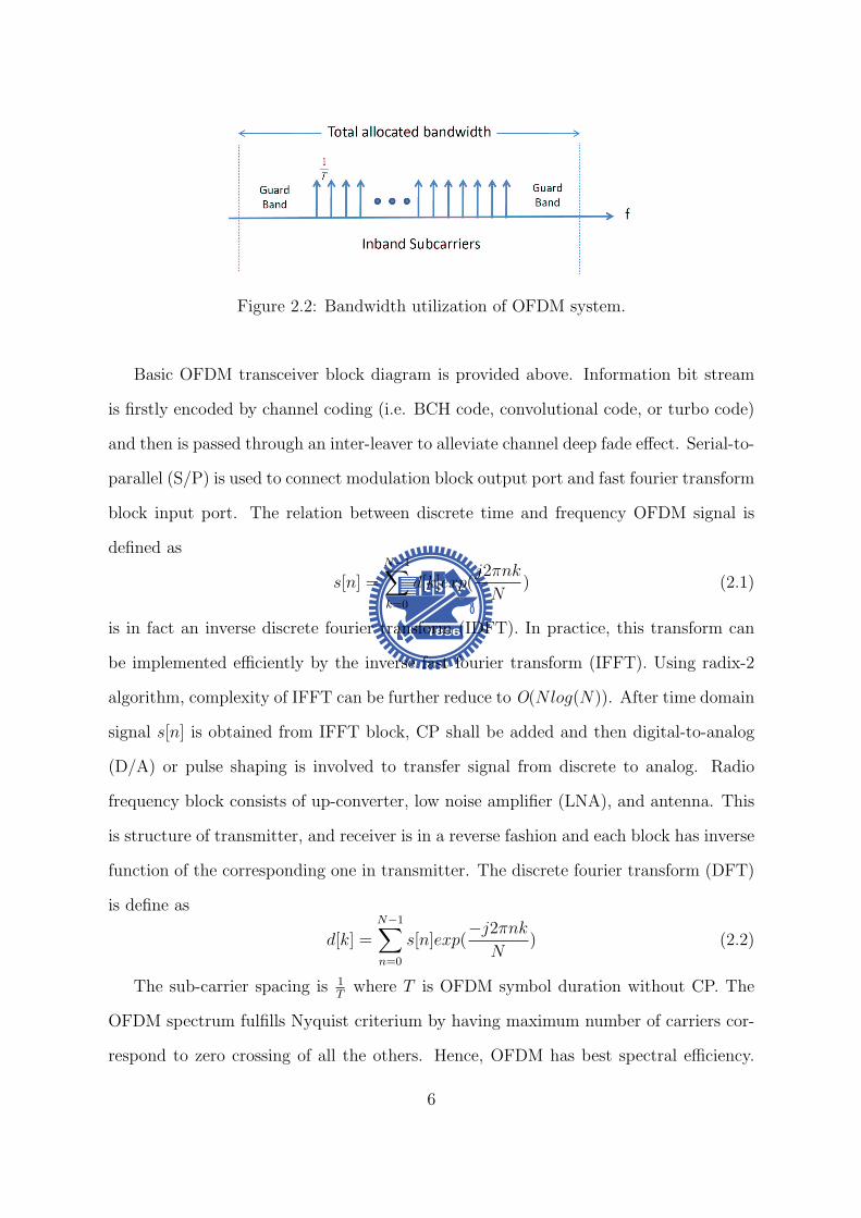
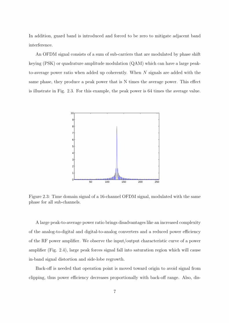
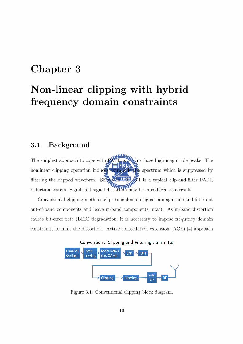
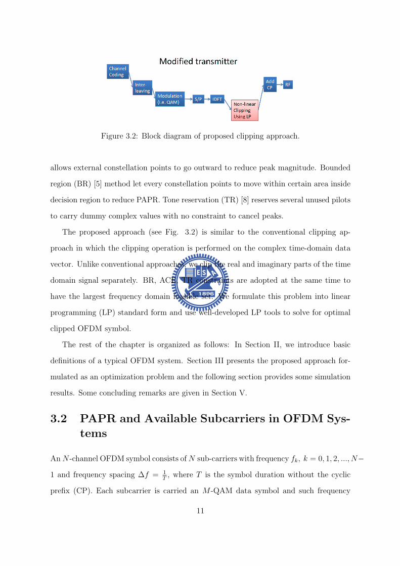
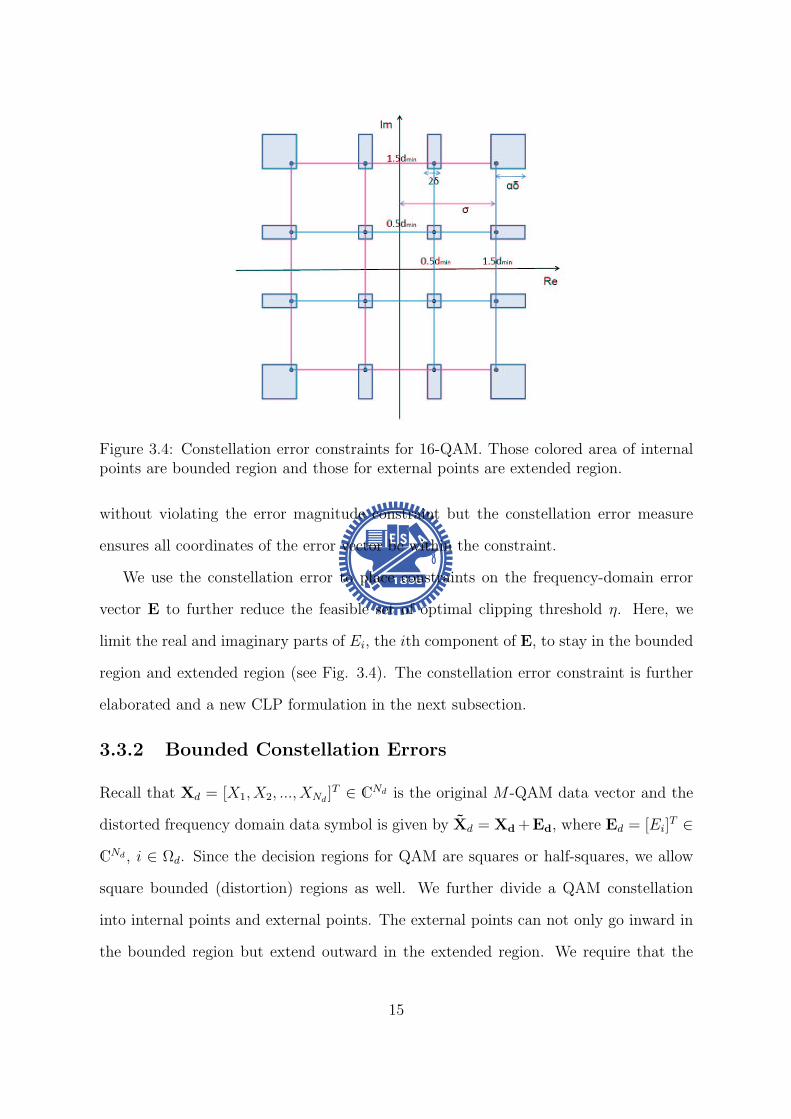
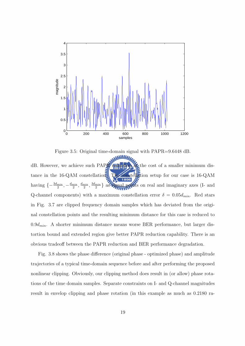
0 200 400 600 800 1000 12000
05
1
15
2
25
3
35
4
samples
mag
nitu
de
Figure 35 Original time-domain signal with PAPR=96448 dB
dB However we achieve such PAPR reduction at the cost of a smaller minimum dis-
tance in the 16-QAM constellation The constellation setup for our case is 16-QAM
having minus3dmin
2minusdmin
2 dmin
2 3dmin
2 as signal points on real and imaginary axes (I- and
Q-channel components) with a maximum constellation error δ = 005dmin Red stars
in Fig 37 are clipped frequency domain samples which has deviated from the origi-
nal constellation points and the resulting minimum distance for this case is reduced to
09dmin A shorter minimum distance means worse BER performance but larger dis-
tortion bound and extended region give better PAPR reduction capability There is an
obvious tradeoff between the PAPR reduction and BER performance degradation
Fig 38 shows the phase difference (original phase - optimized phase) and amplitude
trajectories of a typical time-domain sequence before and after performing the proposed
nonlinear clipping Obviously our clipping method does result in (or allow) phase rota-
tions of the time domain samples Separate constraints on I- and Q-channel magnitudes
result in envelop clipping and phase rotation (in this example as much as 02180 ra-
19
0 200 400 600 800 1000 12000
05
1
15
2
25
samples
mag
nitu
de
Figure 36 Clipped time-domain signal with PAPR=59015 dB
minus4 minus3 minus2 minus1 0 1 2 3 4minus4
minus3
minus2
minus1
0
1
2
3
4
real
imag
Figure 37 Constellation of distorted frequency-domain signal achieving 37433 dBPAPR reduction
20
0 200 400 600 800 1000 12000
05
1
15
2
25
3
time (n)
ma
gn
itud
e
originaloptimizedclipping threshold
0 200 400 600 800 1000 1200minus4
minus3
minus2
minus1
0
1
2
3
4
time (n)
ph
ase
diff
ere
nce
(ra
dia
n)
Figure 38 Phase difference and amplitude trajectories of a typical time-domain se-quence before and after nonlinear clipping
dian) As mentioned before phase rotation gives us an extra degree of freedom for
PAPR reduction The optimal rotated phase is obtained by solving the corresponding
CLP problem (311)
Simulated BER performance of the conventional OFDM and error vector optimized
OFDM schemes in AWGN channels is given in Fig 310 As expected the larger the
allowed constellation error is the greater the PAPR reduction becomes As mentioned
before since the constellation (frequency domain) error reduces the minimum-distance
of the signal set it also degrades the BER performance In this figure we find that a
constellation error bound of δ = 005dmin gives BER performance better than that with
a bounded error of δ = 01dmin It is clear that the amount of PAPR reduction is an
increasing function of the allowed frequency domain distortion bound
Figs 46 and 310 indicate that our clipping scheme yields a better PAPR perfor-
mance than that achieved by RCF-BD while maintaining the same BER performance
This PAPR reducing gain is due to the fact that the error vector used in RCF-BD has
21
4 5 6 7 8 9 10 11 12 13
10minus4
10minus3
10minus2
10minus1
100
dB
CC
DF(
prob
(PA
PR
gt X
0))
Original P
av=10000
Proposed(δ=005dmin
) Pav
=10213
Proposed(δ=01dmin
) Pav
=09600
ACE Pav
=1084
RCFBD Pav
=10206
Figure 39 Effective PAPR gain for 16-QAM 256-carrier OFDM symbol with L=4 over-sampling for δ = 005dmin δ = 01dmin ACE RCFBD and separated coordinate PAPR
4 5 6 7 8 9 10 11 12 13
10minus3
10minus2
10minus1
SNR(dB)
Bit
Err
or R
ate
Original P
av=10000
δ=005dmin
Pav
=10213
δ=01dmin
Pav
=09600
ACE Pav
=1084
RCFBD Pav
=10206
Figure 310 BER of a 16-QAM and 256-carrier OFDM system
22
not been optimized
Although both ours and the ACE schemes use an optimization procedure to reduce
PAPR and our algorithm outperforms the ACE scheme by imposing BDrsquos A BD region
allows optimal modifications for distorted data points it enlarges the feasible set of linear
programming problem whence leads to a greater likelihood to find a solution with lower
PAPR
35 Chapter Summary
In this chapter we present a novel nonlinear clipping technique that extends the RCF-BD
and TR concepts to reduce the PAPR of OFDM signals We formulates the proposed
algorithm as one for solving a CLP problem The solution can be easily found by
following the established procedure The proposed approach does not have to modify
the receiver structure and needs not to send side information Moreover our algorithm
guarantees that the optimal error vector is obtained and the resulting PAPR value is
minimized under certain BD constraints The complexity of our algorithm can be greatly
reduced by if a fast algorithm to solve the corresponding CLP problem can be found
23
Chapter 4
Selective Mapping without SideInformation
41 Background
The basic idea of selective mapping (SLM) is to scramble an OFDM frame (symbol) by
a set of known sequences of the same length and select the scrambled (SLM-encoded)
one with the smallest PAPR for transmission
For uncorrelated SLM sequences the resulting SLM-encoded OFDM signals and
the corresponding PAPRrsquos will be uncorrelated Hence if the PAPR ratio for original
OFDM symbol has probability p of exceeding a certain level the probability for the
OFDM symbol using k SLM sequences is decreased to pk
There are three major design issues related to the SLM scheme namely encoder
and decoder complexities SLM sequences design and side information (SI) about the
scrambling sequence The designs presented in this chapter emphasize the latter two
concerns while the complexity is considered as a secondary issue We proposed a sequence
design which hides SI in each SLM sequence Since each sequence is distinguishable a
blind sequence detector can be used at receiver and data throughput is increased In
addition the implementation of proposed sequences are easy and memory usage is less
24
Figure 41 Original SLM encoder
42 System Model
Consider an OFDM system which transmits frequency domain OFDM symbol x =
[x(0) x(1) x(N minus 1)] in parallel using N sub-carriers fl l = 0 1 2 N minus 1 with
frequency spacing ∆f = 1T T being the symbol duration without the cyclic prefix (CP)
We assume that x(i) isin Q are M -PSK symbols whence Q is the set of constellation
points To reduce the resulting PAPR x is modified by one of sequences in the set
sk = [sk0 s
k1 s
kNminus1] k isin K where k is the sequence index and K can be regarded
as the set of selective mapping sequences
The SLM encoder chooses the encoded sequence y which resulting in a modified
sequence with the smallest PAPR value In other words neglecting the cyclic prefix the
transmitted frequency domain sequence is given by
y = si macr x i = arg minkisinK
PAPRIDFT (sk macr x) (41)
where macr represents the Hadamard product
25
After removing the prefix part and assuming perfect receiver synchronization the
received signal can be expressed as
r = hmacr y + w = hmacr si macr x + w (42)
where h = [h0 h1 middot middot middot hNminus1] is the frequency-domain channel response (CR) and w is
an zero mean white Gaussian noise vector with covariance σ2nI Since the operation macr
is commutative and slowasti macr r = hmacr x + wprime where wprime has the same statistical distribution
as w if h and the mapping sequence sk are known then
slowastk macr hlowast macr rmacr |h|minus2 = x + vdef= rprime (43)
where |h|minus2 = [|h0|minus2 |h1|minus2 middot middot middot |hNminus1|minus2] and v = [v0 v1 middot middot middot vNminus1] is a vector of
independent (but not identically) distributed Gaussian random variables Under this
circumstance the ML data detector is given by
x(skh)def= xk = D[rprime] (44)
where D[rprime] is the vector obtained by making componentwise MPSK decisions
Figure 42 SLM decoder proposed by Tellambura and Jayalath in [10]
26
The above discussion suggests that when the true CR is known the optimal detector
is
(x s) = arg minkisinK
L(r xk sk) (45)
where
L(r xk sk) =Nminus1sumn=0
||r[n]minus h[n]sk[n]xk[n]| |2 (46)
The pairwise error probability (PEP) P [(xi si) rarr (xk sk)|h] that the transmitted 2-
tuple (xi si) is erroneously decoded as (xk sk) is given by
P [(xi si) rarr (xk sk) |h] = PL(r xk sk) ge L(r xi si) (47)
Since
L(r xk sk) ge L(r xi si) (48)
or equivalently
Nminus1sumn=0
||r[n]minus h[n]sk[n]xk[n]||2 geNminus1sumn=0
||r[n]minus h[n]si[n]xi[n]||2 (49)
the PEP can be calculated as
P [(xi si) rarr (xk sk)|h]
=Nminus1prodn=0
Q
radic2 ||h[n]||2||si[n]xi[n]minus sk[n]xk[n]||2
No
(410)
Using the Chernoff bound
Q(x) le exp(minusx22) (411)
we obtain
P [(xi si) rarr (xk sk)|h]
leNminus1prodn=0
exp(minus||h[n]||2||si[n]xi[n]minus sk[n]xk[n]||2)
= exp
(minus
Nminus1sumn=0
||h[n]||2||si[n]xi[n]minus sk[n]xk[n]||2)
(412)
27
For AWGN or slow fading channels the upper-bound becomes
P [(xi si) rarr (xk sk)|ho] le exp(minush2w||sixi minus skxk||22) (413)
where hw = 1N0 (AWGN) or hw = minn h[n] (slow fading) Assuming equally signaling
and defining
Di = mink 6=ikisinK
||si macr xi minus sk macr xk||22 (414)
we express the average conditional symbol error probability (SEP) as
Ps(e) lesumiisinK
sum
kisinKminusiP (si)P [(xi si) rarr (xk sk)|ho]
le 1
|K|sumiisinK
exp(minush2Di) (415)
To minimize the average SEP the minimum Euclidean distance between si and any
other sequences Di should be maximized and which leads to an optimization problem
that could be formulated as follow
max Di
st si = [ejφi0 ejφi
1 ejφiNminus1 ] φi
n isin [0 2π)
sk = [ejφk0 ejφk
1 ejφkNminus1 ] φk
n isin [0 2π)
i isin K k isin Kminus i
where Di = mini 6=kikisinK
||si macr xi minus sk macr xk||22 (416)
For frequency selective fading channels with subcarrier spacing greater than the coherent
bandwidth h[n]rsquos can be modelled as identical and independent distributed random
variables hence we have [10]
P [(si xi) rarr (sk xk)|h]
(2Nminus1N )(SNR)minus2N
Nminus1prodn=0
|si[n]xi[n]minus sk[n]xk[n]|2(417)
whereNminus1prodn=0
|si[n]xi[n]minus sk[n]xk[n]|2 is the product distance between (si xi) and (sk xk)
28
43 Sequence design criteria
When M -PSK modulation is applied the expected value of relative Euclidean distance
between arbitrary two length-N SLM sequences of SLM decoder proposed in [10] can be
calculated as
Dlb =NM
π2
int πM
0
sinθ
2dθ
=4MN
π(1minus cos
π
2M) (418)
It can be proved that any polyphase sequences can have larger expected minimum pair-
wise distance than Dlb
By observing this fact two criteria have be found
bull 1)Every entry of a sequence should have distinct value to corresponding entry of
any other sequence That means a nonzero minimum distance shall be preserved
between the corresponding entry of arbitrary two sequences
bull 2)The magnitude of entries of SLM sequences is constant magnitude 1 Variable
magnitude might cause noise enhancement at receiver site
To accomplish the above two criteria unit circle shall be discretized into finite and equal-
spaced points and every entry of sequences has to take a value among all these discrete
points In addition the discretizing process ensures sequences become polyphase thus
generalized Euclidean distance Di is larger than Dlb After the discretizing process the
discrete total distance space is limited Our goal is to minimize the blind detection error
rate thus one more design criterion is introduced
bull 3)Because of the lack of prior knowledge of sequence selection each sequence has
the same probability of being selected By observing equation (415) A obvious
solution is to have all the pairwise distance to be equal Therefore Di should be
forced to be equal to Davg for all i
29
where Davg will be provided in section V we introduce group theory and use prime
number finite field to construct a set of sequences which could have equal pairwise
distance Proposed sequence design is optimal in the sense of discrete phase and is
easily constructed in the mean time memory requirement is less
For the next two sections we will first review the structure of the cyclic group G and
the definition of characters of finite field GF (p) and then use the knowledge of group
theory to construct a set of sequences which satisfies these three criteria
44 A Review on Group Theory
Let a be a generator of the finite cyclic group G ie G= 〈a〉 = an n isin Z Z being
the set of integers and denote the order of a by o(a) the cardinality of G by |G| We
immediately have |G| = |〈a〉| = o(a) Furthermore if |G| = p is prime then any non-
identity element of G is a generator ie G=〈g〉 and o(g) = p forall g isin Ge where e is
the identity of G
The set of all pth roots of unity in G Up(G) = a|o(a) = p a isin G is obviously a
cyclic group under the multiplication operation as forall a b isin Up(G) (ab)p = apbp = e rArrab isin Up(G) Now if G is the set of complex numbers C then e = 1 and Up(C) =
ej2πkp k = 1 2 middot middot middot p By denoting Wp = ej2πp we have Up(C) = 〈W kp 〉 for all k
An alternative statement is
Property 1 Define the listing vector generated by the seed g where g is a pth root of
unit then s(g) = (g0 g1 middot middot middot g(pminus1)) Two listing vectors generated by different seeds
are permuted version of each other ie
s(Wmp ) = s(W n
p )P forall m 6= n isin Z 0 (419)
where P is a permutation matrix
Note that s(W 0p ) = (1 1 middot middot middot 1) is the all-1 vector
30
45 Proposed SLM Sequence Design
In this section we will apply our knowledge of group characters to present proposed
sequence design for general M -PSK modulation and give an example of SLM sequences
under QPSK modulation
Since (414) is the combination of s and M -PSK data x x Data effect shall be
taken into consideration the ML decoder only count the relative distance from de-
SLM symbol to the nearest constellation point every decision region is equivalent in the
sense of calculating relative distance For M -PSK there are M decision boundaries and
every division is equivalent The proposed sequences design consists of two parts the
deterministic part sd and the data scrambling part sr The SLM sequences are obtained
by element-wise multiplying these two parts
s = sd macr sr (420)
The deterministic part is to have entries of sequences in one decision boundary to have
distinguishable value in the relative distance fashion Second the data scrambling part
is to randomly chooses one among all equivalent divisions to make encoded vector un-
correlated Since prime p cyclic group S(p) is chosen for SLM sequences each subgroup
of this cyclic group forms the deterministic part And the primitive element of S(p) is
W 1Mp Mp-th root of unity
The expression of sequence generated by element gk is
S(gk) = [s(g1k) s(g
2k) s(g
(pminus1)k )]
= [W kMpW
2kMp W
(pminus1)kMp ] (421)
is an Mxp matrix Each column of S(gk) is constructed by s(gnk )
Lemma 1 The pairwise distance between arbitrary two sequences which are con-
structed by different generated elements are equal D(S(gk1)S(gk2)) = D(S(gk1)S(gk3))
gk1 gk2 gk3 isin GF (p)
31
Proof Lemma1 can be easily shown by Preliminary 2 that each sequence has permu-
tation relation to any other sequence And the detail proof can be referred to Appendix
And the subtraction of arbitrary two sequences also has permutation relation There-
fore the pairwise distance is equal for arbitrary two sequences If distance of a complete
distance is defined as d then the minimum pairwise distance of arbitrary two sequences
is
D(S(gk1)S(gk2)) = d (422)
By Lemma 1 we can satisfy the third design criterion that pairwise distance of
arbitrary two sequences is equal
Lemma 2 The pairwise distance of any two sequences is equal to Davg
Proof Entries of all sequences with same index are a complete period of finite field
such that the total distance space for length-pminus 1 sequences within a decision region is
(p minus 1)d and the average distance is Davg = d It is easy to see that Davg is equal to
(422)
It is believed that the randomness in frequency domain is inversely proportional to
the PAPR value of the OFDM symbol Our goal is to have uncorrelated SLM sequences
Hence the data scrambling part of proposed SLM sequences has to be uncorrelated so
skr = [sk
r [1] skr [2] sk
r [pminus 1]] the data scrambling part of k-th sequence is generated by
probability mass function (pmf)
P (rn = s) =1
M s = 1 2 M n = 0 pminus 1 (423)
and each entry skr [n] is to indicate which division is used sk
r is corresponding to the
location of 1 in the row of the matrix Uk and others are zeros and we can have a indicator
vector by multiplying Uk with division matrix D = [ej2πM e
j2π(Mminus1)M ]T which consists of
representations of all decision boundaries of M-PSK Then the data scrambling sr part
of sequence can be represented as
skr = (UkD)T (424)
32
Figure 43 Distribution of generated element gk on unit circle
In the following we provide an example of p = 5 QPSK SLM sequences In QPSK
modulation the primitive element is W 14times5 = W 1
20 and the data effect phase vector
D = [W 04 W 1
4 W 24 W 3
4 ]T and the SLM sequence with generator element g1 is
S(g1) = [W 1times120 W 2times1
20 W 3times120 W 4times1
20 ]
The sequences with generator elements g2 g3 and g4 are
S(g2) = [W 1times220 W 2times2
20 W 3times220 W 4times2
20 ]
S(g3) = [W 1times320 W 2times3
20 W 3times320 W 4times3
20 ]
S(g4) = [W 1times420 W 2times4
20 W 3times420 W 4times4
20 ]
Then we have to choose one combination out of all possible sequences we use matrix
Uk k isin K to determine which expression is taken
Ex u1 = [1 3 2 2] implies that matrix U1 is
U1 =
1 0 0 00 0 1 00 1 0 00 1 0 0
33
and the corresponding sequence with generator element g1 is
s1 = [W 1times120 W 2times1
20 W 3times120 W 4times1
20 ]macr (U1D)T
= [W 1times120 W 2times1
20 W 24 W 3times1
20 W 14 W 4times1
20 W 14 ]
Sequence with generator element g2 with random vector u2 = [1 1 4 2] and the
matrix U2 is
U2 =
1 0 0 01 0 0 00 0 0 10 1 0 0
s2 = [W 1times220 W 2times2
20 W 3times220 W 4times2
20 ]macr (U2D)T
= [W 1times220 W 2times2
20 W 3times220 W 3
4 W 4times220 W 1
4 ]
Sequence with generator element g3 with random vector u3 = [3 1 2 4] and the
matrix U3 is
U3 =
0 0 1 01 0 0 00 1 0 00 0 0 1
s3 = [W 1times320 W 2times3
20 W 3times320 W 4times3
20 ]macr (U3D)T
= [W 1times320 W 3
4 W 2times320 W 3times3
20 W 14 W 4times3
20 W 34 ]
Sequence with generator element g4 with random vector u4 = [2 4 1 1] and the matrix
U4 is
U4 =
0 1 0 00 0 0 11 0 0 01 0 0 0
s4 = [W 1times420 W 2times4
20 W 3times420 W 4times4
20 ]macr (U4D)T
= [W 1times420 W 1
4 W 2times420 W 3
4 W 3times420 W 4times4
20 ]
Once we generate uk k = 1 pminus 1 from uniform distribution in (423) it is fixed and
should be known for both transmitter and receiver side
34
Figure 44 Block diagram of low complexity SLM encoder
46 Low Complexity SLM Encoder
An SLM scheme using U SLM sequences needs U IFFT operations to complete the
encoding Since proposed SLM sequences have good properties that sequences are com-
bined with deterministic term and data scrambling term the encoding procedure of SLM
using proposed SLM sequences can be simplified by using several circular shift units and
conversion blocks
For the modified encoder the deterministic part of our SLM sequence generated by
gk k = 1 pminus 1 is
S(gk) = [s(g1k) s(g
2k) s(g
(p)k )]
= [W kMpW
2kMp W
(p)kMp ] (425)
which is obtained by using an ktimesn0 = ktimes NLMp
circular shift in time domain where N is
number of sub-channel L is over-sampling factor M denotes M -PSK and p is chosen
for prime group
35
A time-frequency fourier transform pair has a updown sampling property that if
frequency domain sequence is repeated l times time domain pair is up-sampled l times
Ex [a b c d]-iquest[e f g h] is a frequency-time fourier pair where [a b c d] is frequency
domain sequence and [e f g h] is time domain pair of [a b c d] If [a b c d] is repeated
2 times and becomes [a b c d a b c d] time domain pair becomes [e 0 f 0 g 0 h 0]
We would take this property to implement the data scrambling part of proposed SLM
sequences First (p minus 1) 4-tuple sequences are randomly selected from scrambling set
1 jminus1minusj which has 256 combinations in total Each chosen sequence is repeated N4
times and becomes a length N sequence and in effect the corresponding time domain
vector tu will be N -tuple sequence with only 4 non-zero entries A sparse conversion
matrix Su can be formed as
Su = [t(0)u t(1)
u t(NLminus1)u ] (426)
where t(k)u is the circularly down-shifted version of the column vector t
(0)u by k elements
And sparse matrix operation has less complexity than IFFT and circular convolution
Frequency domain operation of proposed SLM sequences can be seen as circular
shift in time domain followed by circular convolution with a sparse signal Deterministic
part is a circular shift operation of data vector and scrambling part can be done by
convolution with a sparse signal Hence the encoding procedure is shown in fig 44
that frequency data vector is converted to time domain vector once Then each branch
represents a circular shift and a sparse conversion for corresponding SLM sequence
Since the proposed low complexity SLM encoder needs cyclic shift by ktimesn0 = ktimes NLMp
elements if ktimesn0 = ktimes NLMp
is not an integer a rounding cyclic shift ktimesn0 = bktimes NLMpc
takes place The integer cyclic shift can be done by left column cyclic shift of sparse
conversion matrix with d = bk times NLMpc columns then the new sparse conversion matrix
is defined as
Su = [t(0+d)u t(1+d)
u t(NLminus1+d)u ] (427)
36
Figure 45 Block diagram of modified low complexity SLM encoder
where d = bk times NLMpc defines the integer part of cyclic shift and t
(k)u is the circularly
down-shifted version of the column vector t(0)u by k elements
47 Simulation Results
In this section we provide some numerical results of our sequence design We consider
an OFDM system with 256 sub-carriers using QPSK modulation for the data carried
on N = 160 available subcarrier and it is operated under frequency selective channel
Since number of carriers is 160 group with order p = 17 shall be used Each subgroup
of S(gk) k = 1 p minus 1 forms sequence have to be repeated 10 times and uk is set
to be uncorrelated In addition there is an all one sequence s0 which means that data
encoded that sequence is equal to original data sequence x
In this chapter random generated sequences and chaotic sequence [12] are used to
compare with proposed sequence design Most widely used chaotic logistic map presented
37
6 7 8 9 10 11 12
10minus3
10minus2
10minus1
100
PAPR(dB)
CC
DF
originalproposedchaoticrandom
Figure 46 CCDF plot of PAPR performance of random sequences chaotic sequencesand proposed sequences design
in [12] is
xn+1 = rxn(1minus xn) 0 le xn lt 1 0 le r le 4 (428)
and r is called the bifurcation parameter The outcome of chaotic generator is distributed
in [0 1] with good correlation properties and the sequence is mapped from xn by the
following function
sc(n) = ej2πxn n = 1 2 160 (429)
Random generated sequences can be generated by mapping the random variable xn
which is uniformly distributed in [0 1] using the same mapping function in (429)
PAPR reduction performance has been proved to be proportional to the number of
SLM sequences as long as SLM seuqneces are uncorrelated ([9] and [13]) Fig 46 shows
that any sequence design which has the same number of uncorrelated sequences will have
the same PAPR performance However sequence index detection probability which is
called key error rate (KER) here can be improved by well-designed sequences and the
38
0 05 1 15 2
10minus5
10minus4
10minus3
10minus2
SNR
Pro
babi
lity
of in
dex
dete
ctio
n fa
ilure
proposedrandomchaotic
Figure 47 Probability of sequence index detection failure under frequency selectivechannel
45 50 55 60 65 700
01
02
03
04
05
06
07
08
09
1
Distance
CD
F
proposedrandomchaotic
Figure 48 Euclidean distance of random sequences chaotic sequences and proposedsequence design
39
0 5 10 15 2010
minus4
10minus3
10minus2
10minus1
100
SNR
KE
R
proposedAlsusaampYang
Figure 49 Probability of sequence index detection failure of proposed sequences andAlsusa and Yang sequences under frequency selective channel
5 6 7 8 9 10 11 1210
minus4
10minus3
10minus2
10minus1
100
PAPR(dB)
CC
DF
(PA
PR
gtη)
originalOne IFFT SLMSLM
Figure 410 CCDF of PAPR performance of original OFDM symbol low complexitySLM encoder and original SLM
40
proposed sequence design provides a promising coding gain that every sequence is NDavg
pminus1
far away from other sequences where Npminus1
have to be integer
Fig 48 shows the minimum pairwise distance of random generated sequences
chaotic sequences and proposed sequence design The minimum pairwise distance of
random generated and chaotic sequences are much less than the minimum pairwise dis-
tance of proposed sequence design As we can see in equation (415) that minimum
distance would dominate performance of blind decoder Fig 57 shows the trend of
this hypothesis and an asymptotically 03dB gain of proposed sequences to random and
chaotic sequences for signal-to-noise ratio (SNR) larger than 15dB Besides our design
criterion is to make all pairwise distance to be equal and fig 48 also shows that our
design satisfy this criterion
Alsusa and Yang [11] proposed an SLM sequences design in the proceedings of ICC
2006 Their design uses the locations of unmodified elements to identify different se-
quences thus receiver has only to detect the locations of unmodified block Their se-
quences have unmodified elements which is ej0 = 1 and other entries with magnitude 1
and phase [0 2π) distributed In fig 49 we can see that proposed design outperforms
Alsusa and Wangrsquos since their design only use part of sequence to identify each SLM
sequence Sequence pattern of proposed design spread through whole sequence hence
full degree of freedom is employed for sequence detection
The proposed low complexity SLM encoder has only one IFFT operation but it has
PAPR loss since sparse conversion block has correlation in frequency domain Although
low complexity SLM encoder has 08dB PAPR loss at CCDF = 104 in fig 410 the
complexity is decreased from O(LNlog(LN)) to O(4LN) While using SLM to be PAPR
reduction scheme the SLM sequences have to be stored in both transmitter and receiver
sides to do the encoding and decoding Only the data scrambling vectors uk k =
1 p minus 1 have to be stored for using proposed sequences It costs log2 M bits of
memory for one entry to store the vectors uk In the case of QPSK 2 bits memory for
41
one element in sequence is needed
The SLM scheme is simple quick and effective in the sense of reducing PAPR
however SLM is not recommended in several latest released standard proposals due to
its sequence index detection failure Since we can achieve the sequence detection failure
probability Pe = 10minus5 at 2dB SNR which is acceptable in wireless communication SLM
should be reconsidered to be a main PAPR reduction scheme
48 Chapter Summary
In this chapter a novel selective mapping sequence design is proposed that minimum
pairwise distance of arbitrary two sequences is equal It provides the system a bound
of minimum distance Davg between sequences which has a guaranteed coding gain that
every codeword is separated at least Davg apart And simulation results show that pro-
posed design scheme has more than 03dB gain on sequence index detection probability
and it reaches detection failure probability Pe = 10minus5 at SNR = 2dB which is robust
enough for wireless communication
42
Chapter 5
Selective Mapping with EmbeddedSide Information
In this chapter we present an improved non-blind SLM-based PAPR reduction
scheme which uses SLM as the main PAPR reduction mechanism side information (SI)
is transmitted within the same OFDM symbol The embedded SI is further exploited
to reduce PAPR and enhance SI detection performance
51 System Model
Figure 51 Bandwidth utilization of proposed scheme
We consider an OFDM system with N in-band sub-carriers which can be divided
into data sub-carriers set Sd = ld0 ldDminus1 with cardinality D and SI sub-carriers set
SI = lI0 lIPminus1 with cardinality P X = [X[ld0 ] X[ldDminus1
]] is data vector which
is modulated by quadrature amplitude modulation (QAM) SLM sequence denotes as
suk = [Sk[ld0 ] su[ldDminus1]] and each entry is uniformly distributed in [0 2π) and u isin K
with cardinality |K| = U Given the original OFDM symbol U alternative representa-
43
tions of signal candidates Xu = X macr su can be obtained by element-wise multiplying
the original OFDM symbol with different SLM sequences Furthermore the SI of SLM
sequence which is the index of the used sequence is modulated onto sub-carriers of
SI The SI vector denotes as Ausi = [Au
si[lI0 ] Ausi[lIPminus1
] The entire frequency domain
OFDM symbol can be represented as Xu = [Xu[ld0 ] Xu[ldDminus1] Au
si[lI0 ] Ausi[lIPminus1
]]
which is the scrambled data plus embedded SI
Figure 52 Original SLM encoder with embedded SI
Our scheme consists of two stages In the first stage we choose the one with low-
est PAPR among U different candidate SLM-encoded OFDM symbols Second stage
adopts two different algorithms to reduce PAPR by adjusting the SI symbols meanwhile
having better SI detection error protection The first algorithm employs active constel-
lation extension (ACE) [4] to adjust SI and the second algorithm uses POCS [15] for SI
adjustment
This chapter is organized as follow Section II consider the encoding and insertion of
SI ACE and POCS are introduced in section III Simulation results and brief conclusion
are provided in section IV and V
44
52 Encoding Side Information and Insertion
521 Insertion of the Side Information
The main concern of using SLM scheme is the correctness of SI and channel coding
techniques are involved for having better error protection Original SI bits are log2(U)
and the encoded SI bits are log2(n) if (nk) linear block code is used And the number of
SI sub-carriers can be determined by the ratio of encoded SI bits and modulation type
of SI sub-carriers
P = d n
log2(M)e (51)
where M is the number of constellation points of the modulation type being used The
vector representing SI symbols is generated by a mapping S which maps the index u to
a vector of QAM symbol Ausi
S u rarr Ausi u = 1 U (52)
and the index of Ausi can be seen in figure 51
522 Estimation of Side Information
At the receiver after applying discrete fourier transform (DFT) and zero-forcing equal-
ization the received OFDM frequency symbol is denoted as Y and SI vector is denoted
as Ysi The noisy vector Ysi consists of signal apart Ausi and noise part with variance
σ2n|Hn|2
Maximum likelihood (ML) estimation is applied for decoding sequence index u The
estimate u can be obtained by
u = arg maxu=1U
PrYsi|Ausi
= arg maxu=1U
Pminus1prodn=0
PrYsi[n]|Ausi[n]
= arg minu=1U
Pminus1sumn=0
|Ysi[n]minus Ausi[n]|2
σ2n|Hn|2
(53)
45
In order to execute the ML estimator channel state information |Hn|2 and noise variance
σ2n have to be known
523 Encoding Scheme of SI
Several earlier approaches [16] use (74) Hamming code to encode SI
Example The number of SLM sequences in the set K is 16 so we can use the 3-bit
representation (0 0 0 0) (0 0 0 1) (1 1 1 1) for the sequence index Using the
Hamming code with generator matrix G given by
G =
1 1 0 11 0 1 11 0 0 00 1 1 10 1 0 00 0 1 00 0 0 1
(54)
we obtain 7-bit encoded vectors by c = uG
Since ML estimation is used for decoding sequence index only generator matrix or
generator polynomial is needed for transmitter and receiver
For proposed scheme BCH code is involved for a better error protection capability
One of the advantages of BCH is easy implementation that shift register can be used
to generate encoding sequence Polynomial representation for information bits and gen-
erator polynomial is needed For BCH(3167) information bits should be written as
XX + 1X5 + X4 + X3 + X2 + X + 1 and the generator polynomial is
g(X) = X25+X24+X21+X19+X18+X16+X15+X14+X13+X11+X9+X5+X2+X+1
(55)
The resulting encoded sequence is denoted as cu = [cu[0] cu[31minus 1]]
As we have no posterior information of the peak locations of time domain SLM en-
coded signal the PAPR of SI vector should be minimized If the number of SI bits
(log2(U)) are less than that of the input information bits (k) there is extra degrees of
freedom can be used to find SI with smaller PAPR In proposed scheme the number
46
of SLM sequences is U = 8 and the (3167) BCH code is used to encode SI Hence
we choose the eighth lowest PAPR sequences among all the possible encoded BCH se-
quences It shall be mentioned that this process shall include the modulation of encoded
bits onto SI sub-carriers and the results will be different if the modulation scheme is
different
53 Side Information Adjustment Algorithm
Our scheme is a two-stage algorithm (see Fig 52) whose first stage involves the insertion
of SI and the selection among possible candidate SLM-encoded vectors This section
discusses the second stage operations where clipping is employed while frequency domain
feasible set is defined on SI sub-carries only There are two algorithm being adopted
531 Problem Formulation
The effect of inserted SI can be viewed as a time domain signal au = IDFTAusi which
is contributed by SI only plus the time domain SLM encoded signal x = IDFTXAnd the addition of the two signals should be minimized below threshold η This can
be formed as an optimization problem
min η
st
||x||infin le η
where au = IDFTAusi + esi
x = IDFTX
||x||infin = ||x + au||infinin variables esi isin CNL η isin R
(56)
47
SLM encoded signal x = IDFTX shall not be changed to maintain the bit error rate
(BER) performance thus only SI part au can be modified to reduce PAPR There are
two algorithms active constellation extension (ACE) and projection onto complex set
(POCS) can be adopted and they will be introduced in the following two subsections
532 Active Constellation Extension for SI Adjustment
Figure 53 Extended region of QPSK denoted as F
The encoded SI vector is binary and quadrature phase shift keying (QPSK) is used
as the mapping S from sequence index u to SI vector Ausi Thus the number of SI sub-
carriers can be determined by d nlog2(4)
e ACE algorithm is used to modified Ausi within
the frequency domain constraint set By doing so the PAPR of the modified symbol
will be reduced and as the constellation points are further apart from decision boundary
the detection error protection is improved Here we define frequency domain extended
region as feasible set F for modified SI symbol in figure 53
48
The new PAPR reduction problem can be written as follow
min η
st
||x||infin le η
where au = IDFTAusi + esi
x = IDFTX
||x||infin = ||x + au||infinin variables esi isin CNL η isin R
(57)
One simple way is iterative clipping and filtering that the time domain signal is first
clipped and followed by restoring data vector back to its original value of the SLM
encoder output and projecting the SI symbol back to frequency domain feasible set F
The iterative signal update can be written as
xi+1 = xi + microei (58)
where i is the iteration number and xi is the time domain iterative signal The clipping
rule is
Rex[n] =
Rexi[n] |Rexi[n]| le η
η |Rexi[n]| gt η
Imx[n] =
Imxi[n] |Imxi[n]| le η
η |Imxi[n]| gt η
x = Rex+ j lowast Imx (59)
Thus the time domain error vector is eiclip = x minus xi and the frequency domain error
vector can be obtained by Eiclip = DFTei
clip And the frequency update signal Ei has
to satisfy several predefined frequency domain constraint that error at data part should
be zero Ei[n] = 0 n = ld0 ldDminus1and error at SI has to be within frequency feasible set
Ei[n] =
Ei[n] = Eclip[n] n = lI0 lIPminus1
if Eclip[n] isin E
Ei[n] = proj(Eclip[n]E) n = lI0 lIPminus1 otherwise
49
where proj(aA) is the function that project a onto the nearest point in set A And the
time domain update signal is ei = IDFTEiJones [4] introduces smart gradient projection (SGP) algorithm that step size micro is
updated for every iteration The ACE-SGP algorithm is list as follow
Step 1 InitializationSet iteration number i = 0 and clipping threshold η
Step 2 x is obtained by clipping xi with threshold ηCompute the update signal of ei[n] by ei
clip = xminus xiand compute projection of ei[n] along xi[n] for every sample
eproj[n] = ltxi[n]lowasteilowast[n]|xi[n]| n = 0 N minus 1
Step 3 Given xi compute maximum magnitude E and thecorresponding sample position nmax for iteration iP = max
n|xi[n]|
nmax = arg maxn|xi[n]|
Step 4 Compute approximate balancing for eproj[n] gt 0
micro[n] = Pminus|xi[n]|eproj [n]minuseproj [nmax]
Choose the minimum micro as step size
Step 5 Update the signal xi+1 = xi + microei with variable step size micro
Step 6 Iteratively execute from step 2 to step 5If micro is negative stop algorithm
Table 51 Active constellation extension with smart gradient projection algorithm
Usually the SGP algorithm converges to a near-optimal solution within 5 iterations As
we can see the feasible set of ACE algorithm is only in a quadrant which means the
phase of SI symbol can only be changed from minusπ4
to π4 In the following we come up
with an idea to have phase of SI symbol to change from 0 to 2π and the phase degree
of freedom is employed And this is introduced next for AM modulation of SI vector
50
533 Projection onto Complex Set for SI Adjustment
Since phase degree of freedom of SI symbol is concerned SI symbol should be freely
moved from 0 to 2π and carry information on amplitude Thus the mapping rule
S u rarr Ausi is amplitude modulation which maps 0 onto unit circle and 1 onto circle
with radius 2 And the number of SI sub-carriers can be determined by d nlog2(2)
e = n
The mapping S is
Ausi[i] =
1 middot ejθ[i] if cu[i] = 0
2 middot ejθ[i] if cu[i] = 1
where phase θ[i] i = 0 n minus 1 is uniformly distributed in [0 2π) The frequency
domain feasible set C is defined in figure 54
Figure 54 Amplitude modulation for POCS algorithm
51
And the PAPR reduction problem becomes
min η
st
||x||infin le η
|Ausi[i]| le 1 if cu[i] = 0
|Ausi[i]| ge 2 if cu[i] = 1
where au = IDFTAusi + esi
x = IDFTX
||x||infin = ||x + au||infinin variables esi isin CNL η isin R
(510)
As we can see in fig 54 that the outer circle is not a convex set and it can not be
solved by any convex optimization tool thus projection onto complex set algorithm is a
sub-optimal algorithm to take place The following is POCS algorithm
Step 1 Initialization vector x is IDFT of X
Step 2 Enforce x to satisfy the pre-defined threshold ηIf the modified x satisfies x = x then terminatedOtherwise go to step 3
Step 3 Perform DFT to x to obtain X and
restore data part [X[ld0 ] X[ldDminus1]] = X and
project SI part [proj(X[lI0 ]C) proj(X[lIPminus1]C)]
to the closest point in C
Step 4 Iteratively execute step 2 and step 3 until there is no PAPRreduction gain or PAPR is small enough
Table 52 Projection onto Complex Set algorithm
52
Next section simulation results are provided and modified SI symbols by ACE algorithm
and POCS algorithm is observed
54 Numerical Results
In this section we provide several numerical results to show the key error rate (KER)
which is the SI detection probability and CCDF of PAPR performance Also the figures
of modified frequency domain SI is provided For different SI modulation we have
different settings to make them comparable For QPSK modulation of SI an OFDM
symbol with 256 sub-carriers is considered and 152 in-band sub-carriers are further
divided into 136 data sub-carriers and 16 SI sub-carriers However for AM modulation
of SI an OFDM symbol with 512 sub-carriers is considered and 304 in-band sub-carriers
are further divided into 273 data sub-carriers and 31 SI sub-carriers Thus the ratio of
SI sub-carriers and total sub-carriers are equal for both system The number of SLM
sequences is 8 and BCH(3167) is used for SI encoding The system is simulated under
frequency selective channel for error rate performance
First we would like to show the modified SI do locate inside the defined frequency
domain constraint set In fig 55 the modified SI do stay within the extended region
and the red cross stands for original QPSK constellation points and blue circle means
the modified symbol In fig 56 r = 1 red circle stands for the amplitude modulation
for information bit 0 and r = 2 red circle stands for the amplitude modulation for
information bit 1 The symbols do stay within the constraint set with random phase
For both scheme symbols move opposite direction toward decision boundary thus SI
detection probability is improved
The simulated KER and PAPR performance are provided in fig 57 fig 46 In Fig
46 the POCS algorithm and ACE algorithm can further reduce PAPR than orignal
SLM and SLM with inserted SI POCS outperform ACE because POCS has more phase
degree of freedom than ACE As we can see from the constraint set of ACE (Fig 53)
53
minus2 minus15 minus1 minus05 0 05 1 15 2minus2
minus15
minus1
minus05
0
05
1
15
modified SIQPSK points
Figure 55 Location of modified SI symbol using active constellation extension (ACE)algorithm
minus2 minus15 minus1 minus05 0 05 1 15 2minus25
minus2
minus15
minus1
minus05
0
05
1
15
2
25
Modified SIr=1 circler=2 circle
Figure 56 Location of modified SI symbol using projection onto complex set (POCS)algorithm
54
minus10 minus5 0 5 1010
minus5
10minus4
10minus3
10minus2
10minus1
100
SNR(dB)
KE
R
ACEPOCS
Figure 57 Key error rate for ACE and POCS schemes
6 7 8 9 10 11 1210
minus4
10minus3
10minus2
10minus1
100
PAPR(dB)
CC
DF
(PA
PR
gtPA
PR 0)
data onlySLMSLM data with embbeded SIoptimized SI (ACE)
Figure 58 CCDF of PAPR of original SLM SLM embedded SI and SLM with modifiedSI (ACE)
55
5 6 7 8 9 10 11 1210
minus4
10minus3
10minus2
10minus1
100
PAPR(dB)
CC
DF
(PA
PR
gtPA
PR 0)
data onlySLMSLM data with embbeded SIoptimized SI (POCS)
Figure 59 CCDF of PAPR of original SLM SLM embedded SI and SLM with modifiedSI (POCS)
the phase degree of freedom for every symbol is [minusπ4 π4] however for constraint set
of POCs (Fig 54) every symbol has phase degree of freedom from [0 2π) It is believed
that phase degree of freedom is much more effective than magnitude degree of freedom
in the sense of PAPR reduction
Fig 57 shows that there is a 3dB KER performance gap between ACE and POCS
schemes because the minimum distance of QPSK constellation is twice the minimum
distance of Amplitude modulation and also ML symbol-wise estimation is used Despite
of the 3dB gap the KER decreases to 10minus4 at SNR=5 (ACE) and SNR=8 (POCS) Such
performance is robust enough for wireless communication
55 Chapter Summary
In this chapter we provide another option for SI transmission to receiver that SI is
inserted within the same OFDM symbol Two algorithms are proposed to modified
56
SI to further reduce PAPR Simulation results show that with second stage cascaded
PAPR reduction outperforms than original SLM and it reaches KER Pe = 10minus4 at 5dB
and 8dB SNR for ACE and POCS respectively
57
Chapter 6
Conclusion
61 Summary of Contributions
Peak-to-average power ratio is one of the most critical design concerns for OFDM sys-
tems We have presented two new PAPR reduction approaches and a SLM sequence
design in this thesis
We first proposed a nonlinear clipping method with hybrid frequency domain con-
straints to obtain a larger feasible set The PAPR reduction problem is formulated as
a standard linear programming (LP) form which can then be solved by well-developed
LP tools to obtain the optimal clipping threshold and optimal clipped OFDM symbols
A novel SLM sequences design aimed to offer improved blind (non-side-information
aided) detection performance is proposed Our design renders a simple hardware real-
ization with less memory requirement
Our third contribution has to do with side information transmission in an SLM sys-
tem Our scheme inserts the SI in the same OFDM symbol By adjusting SI we further
reduce the PAPR ACE and POCS algorithms are adopted to modify the transmitted
SI
58
62 Some Future Works
The complexity of the LP solution presented is still high for real-time implementation
Better algorithms are needed to reduce the overall the complexity of solving the target
LP problem Finding a mathematical connection between error vector magnitude and
bit error rate performance remains unsolved If such a relationship can be established
then one can solve the PAPR reduction and BER minimization simultaneously
For the SLM-aided OFDM system we believe that both the associated blind de-
coder complexity and performance can be further improved Analysis of the exact blind
sequence detection probability and the corresponding BER performance is also desired
For the proposed SI-aided scheme to become practical we have to reduce the re-
quired number of SI sub-carriers to improve bandwidth efficiency Further complexity
suggestions are always welcome Linear system with sparse solution optimization prob-
lem might be needed to find a near-optimal solution for projection onto convex set
algorithm
59
Appendix
In this Appendix we continue on proving that minimum pairwise distance of any two
arbitrary sequences are equal Here we have three arbitrary sequences
D(S(g1)) = D([W k1MpW
2k1Mp W
(pminus1)k1
Mp ]otimesD) (61)
= [W(k1 mod p)Mp W
(2k1 mod p)Mp W
((pminus1)k1 mod p)Mp ] (62)
k1 isin [0 pminus 1] isin Z
D(S(g2)) = D([W k2MpW
2k2Mp W
(pminus1)k2
Mp ]otimesD) (63)
= [W(k2 mod p)Mp W
(2k2 mod p)Mp W
((pminus1)k2 mod p)Mp ] (64)
k2 isin [0 pminus 1]minus k1 isin Z
D(S(g3)) = D([W k3MpW
2k3Mp W
(pminus1)k3
Mp ]otimesD) (65)
= [W(k3 mod p)Mp W
(2k3 mod p)Mp W
((pminus1)k3 mod p)Mp ] (66)
k3 isin [0 pminus 1]minus k1 k2 isin Z
where D(middot) is the relative distance function of sequence to the nearest constellation
points Since relative distance to constellation points is considered equation (61)(63)(65)
and equation (62)(64)(66) can be seen as to calculate relative distance of those expres-
sion to nearest constellation points
We now use predefined distance function D(x1x2) to calculate the pairwise relative
distance between this three sequences The relative distance between S(g1) and S(g2)
60
can be calculate as
D(S(g1)S(g2)) =
pminus1sumn=0
min |W k1nMp otimesDminusW k2n
Mp otimesD|2 (67)
=
pminus1sumn=0
|W (k1n mod p))Mp minusW
(k2n mod p)Mp |2 (68)
=
pminus1sumn=0
|1minusW((k2minusk1)n mod p)Mp |2 (69)
In (67)ndash(68) we use (mod p) to replace (otimesD) as in (61) and (62)
The relative distance between S(g1) and S(g3) can be calculate as
D(S(g1)S(g3)) =
pminus1sumn=0
min |W k1nMp otimesDminusW k3n
Mp otimesD|2 (610)
=
pminus1sumn=0
|W (k1n mod p)Mp minusW
(k3n mod p)Mp |2 (611)
=
pminus1sumn=0
|1minusW((k3minusk1)n mod p)Mp |2 (612)
(610) is simplified to be (611) in the same sense of (67) and (68)
However s(gnk ) = (W kn
Mp) n = 1 pminus 1 is character vector of group S(p) Since p
is odd prime number it can be shown by () that
s(gn1 minus gn
2 ) = Ps(gn1 minus gn
3 ) (613)
where P is permutation matrix
We can apply this relation to the distance function D(x1x2) since x1 and x2 have
the relation in (613) The corresponding distance character of (69) and (612) are
S21 = |1minusW((k2minusk1)n mod p)Mp | n = 1 pminus 1
S31 = |1minusW((k3minusk1)n mod p)Mp | n = 1 pminus 1
will also satisfy the same relation that
S21 = PS31
61
where P is permutation matrix Therefore
pminus1sumn=0
|1minusW((k3minusk1)n mod p)Mp |2 =
pminus1sumn=0
|1minusW((k2minusk1)n mod p)Mp |2
D(S(g1)S(g2)) = D(S(g1)S(g3)) (614)
and
D(S(g1)S(g2)) = D(S(g2)S(g3))
D(S(g1)S(g2)) = d
D(S(g2)S(g3)) = d (615)
(616)
which prove that arbitrary two sequences of proposed design have equal pairwise dis-
tance
62
Bibliography
[1] T Jiang and Y Wu ldquoAn overview Peak-to-average power ratio reduction tech-
niques for OFDM signalsrdquo Broadcasting IEEE Transactions on Vol 54 Issue 2
Page(s)257 - 268 June 2008
[2] AE Jones TA Wilkinson and SK Barton ldquoBlock coding scheme for reduction of
peak to mean envelope power ratio of multicarrier transmission schemesrdquo Electron
Lett Vol 30 Issue 25 Page(s)2098-2099 8 Dec 1994
[3] ADS Jayalath and C Tellambura ldquoReducing the peak-to-average power ratio of
orthogonal frequency division multiplexing signal through bit or symbol interleavingrdquo
Electron Lett Vol 36 Issue 13 Page(s)1161-1163 22 June 2000
[4] B S Krongold and D L Jones ldquoPAR reduction in OFDM via active constellation
extensionrdquo Broadcasting IEEE Transactions on Vol49 No3 pp258-268 Sept
2003
[5] S K Deng and M C Lin ldquoRecursive clipping and filtering with bounded distortion
for PAR reductionrdquo Communications IEEE Transactions on Vol55 No1 pp227-
230 Jan 2007
[6] S Janaaththanan C Kasparis and B G Evans ldquoA gradient based algorithm for
PAPR reduction of OFDM using tone reservationrdquo Vehicular Technology Confer-
ence 2008 VTC Spring 2008 IEEE Page(s)2977 - 2980 11-14 May 2008
63
[7] J Armstrong ldquoPeak-to-average power ratio reduction for OFDM by reapeted clipping
and frequency domain filteringrdquo Electron Lett vol38 pp 246-247 Feb 2002
[8] J Tellado and J M Cioffi ldquoPAR reduction in multicarrier transmission systemsrdquo
ANSI Document T1E14 Technical Subcommittee 2008
[9] RW Bauml RFH Fischer and JB Huber ldquoReducing the peak-to-average power
ratio of multicarrier modulation by selected mappingrdquo Electron Lett Vol 32 no
22 pp 2056-2057 Oct 1996
[10] ADS Jayalath and C Tellambura ldquoSLM and PTS peak-power reduction of OFDM
signals without side informationrdquo Wireless Comm Vol 4 no 5 pp 2006-2013 Sept
2005
[11] E Alsusa and L Yang ldquoNovel redundancy-free and SER-improved selective map-
ping technique with coded phase sequences for PAPR reduction in OFDM systemsrdquo
International Communication Conference 2006 ICC 2006rdquo Vol 4 no 5 pp 2887-
2892 June 2006
[12] G Heidari-Bateni CD McGillem ldquoChaotic sequences for spread spectrum an
alternative to PN-sequencesrdquordquo Proceedings of 1992 IEEE InternationalConference
on Selected Topics in Wireless Communicatiom Vancouver Canada pp437-440
25-26 June 1992
[13] K Bae EJ Powers ldquoDistribution of envelope power using selected mapping in
OFDM systems with nonlinearityrdquo Acoustics Speech and Signal Processing 2008
ICASSP 2008 IEEE International Conference on pp3065-3068 Mar 31-Apr 4
2008
[14] RA Scholtz and LR Welch ldquoGroup characters Sequences with good correlation
propertiesrdquo IEEE Trans Inform Theoty vol 24 no 5 pp 537 - 545 Sep 1978
64
[15] R K Martin and M Haker ldquoReduction of peak-to-average power ratio in transform
domain communication systemsrdquoIEEE trans Wireless Comm vol8 no9 pp4400-
4405 Sept 2009
[16] ADS Jayalath C Tellambura ldquoPeak-to-average power ratio reduction of an
OFDM signal using data permutation with embedded side informationrdquo Circuits and
Systems 2001 ISCAS 2001 The 2001 IEEE International Symposium on vol4
pp562-565 6-9 May 2001
[17] D Divsalar MK Simon ldquoTrellis coded modulation for 4800-9600 bitss trans-
mission over a fading mobile satellite channelrdquo Selected Areas in Communications
vol5 no2 pp 162- 175 Feb 1987
[18] D Divsalar MK Simon ldquoThe design of trellis coded MPSK for fading chan-
nels performance criteriardquo Communications IEEE Transactions on vol36 no9
pp1004-1012 Sept 1988
65
66
作 者 簡 歷
董原豪台北市人1986 年生 台北市立成功高級中學 200109~200406
國立交通大學電信工程學系 200409~200806
國立交通大學電信工程研究所系統組 200809~201006
Graduate Course
1 Random Process
2 Digital Signal Processing
3 Digital Communications
4 Coding Theory
5 Information Theory
6 Detection and Estimation Theory
7 Matrix Computations
8 Computer Communication Networks
9 Wireless Communications
- 論文封面pdf
- 中文摘要pdf
- 英文摘要pdf
- 誌 謝pdf
- mainpdf
- 作 者 簡 歷pdf
-
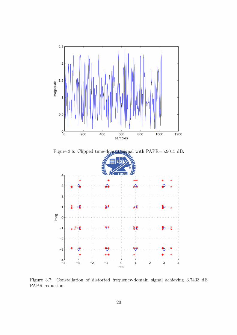
0 200 400 600 800 1000 12000
05
1
15
2
25
samples
mag
nitu
de
Figure 36 Clipped time-domain signal with PAPR=59015 dB
minus4 minus3 minus2 minus1 0 1 2 3 4minus4
minus3
minus2
minus1
0
1
2
3
4
real
imag
Figure 37 Constellation of distorted frequency-domain signal achieving 37433 dBPAPR reduction
20
0 200 400 600 800 1000 12000
05
1
15
2
25
3
time (n)
ma
gn
itud
e
originaloptimizedclipping threshold
0 200 400 600 800 1000 1200minus4
minus3
minus2
minus1
0
1
2
3
4
time (n)
ph
ase
diff
ere
nce
(ra
dia
n)
Figure 38 Phase difference and amplitude trajectories of a typical time-domain se-quence before and after nonlinear clipping
dian) As mentioned before phase rotation gives us an extra degree of freedom for
PAPR reduction The optimal rotated phase is obtained by solving the corresponding
CLP problem (311)
Simulated BER performance of the conventional OFDM and error vector optimized
OFDM schemes in AWGN channels is given in Fig 310 As expected the larger the
allowed constellation error is the greater the PAPR reduction becomes As mentioned
before since the constellation (frequency domain) error reduces the minimum-distance
of the signal set it also degrades the BER performance In this figure we find that a
constellation error bound of δ = 005dmin gives BER performance better than that with
a bounded error of δ = 01dmin It is clear that the amount of PAPR reduction is an
increasing function of the allowed frequency domain distortion bound
Figs 46 and 310 indicate that our clipping scheme yields a better PAPR perfor-
mance than that achieved by RCF-BD while maintaining the same BER performance
This PAPR reducing gain is due to the fact that the error vector used in RCF-BD has
21
4 5 6 7 8 9 10 11 12 13
10minus4
10minus3
10minus2
10minus1
100
dB
CC
DF(
prob
(PA
PR
gt X
0))
Original P
av=10000
Proposed(δ=005dmin
) Pav
=10213
Proposed(δ=01dmin
) Pav
=09600
ACE Pav
=1084
RCFBD Pav
=10206
Figure 39 Effective PAPR gain for 16-QAM 256-carrier OFDM symbol with L=4 over-sampling for δ = 005dmin δ = 01dmin ACE RCFBD and separated coordinate PAPR
4 5 6 7 8 9 10 11 12 13
10minus3
10minus2
10minus1
SNR(dB)
Bit
Err
or R
ate
Original P
av=10000
δ=005dmin
Pav
=10213
δ=01dmin
Pav
=09600
ACE Pav
=1084
RCFBD Pav
=10206
Figure 310 BER of a 16-QAM and 256-carrier OFDM system
22
not been optimized
Although both ours and the ACE schemes use an optimization procedure to reduce
PAPR and our algorithm outperforms the ACE scheme by imposing BDrsquos A BD region
allows optimal modifications for distorted data points it enlarges the feasible set of linear
programming problem whence leads to a greater likelihood to find a solution with lower
PAPR
35 Chapter Summary
In this chapter we present a novel nonlinear clipping technique that extends the RCF-BD
and TR concepts to reduce the PAPR of OFDM signals We formulates the proposed
algorithm as one for solving a CLP problem The solution can be easily found by
following the established procedure The proposed approach does not have to modify
the receiver structure and needs not to send side information Moreover our algorithm
guarantees that the optimal error vector is obtained and the resulting PAPR value is
minimized under certain BD constraints The complexity of our algorithm can be greatly
reduced by if a fast algorithm to solve the corresponding CLP problem can be found
23
Chapter 4
Selective Mapping without SideInformation
41 Background
The basic idea of selective mapping (SLM) is to scramble an OFDM frame (symbol) by
a set of known sequences of the same length and select the scrambled (SLM-encoded)
one with the smallest PAPR for transmission
For uncorrelated SLM sequences the resulting SLM-encoded OFDM signals and
the corresponding PAPRrsquos will be uncorrelated Hence if the PAPR ratio for original
OFDM symbol has probability p of exceeding a certain level the probability for the
OFDM symbol using k SLM sequences is decreased to pk
There are three major design issues related to the SLM scheme namely encoder
and decoder complexities SLM sequences design and side information (SI) about the
scrambling sequence The designs presented in this chapter emphasize the latter two
concerns while the complexity is considered as a secondary issue We proposed a sequence
design which hides SI in each SLM sequence Since each sequence is distinguishable a
blind sequence detector can be used at receiver and data throughput is increased In
addition the implementation of proposed sequences are easy and memory usage is less
24
Figure 41 Original SLM encoder
42 System Model
Consider an OFDM system which transmits frequency domain OFDM symbol x =
[x(0) x(1) x(N minus 1)] in parallel using N sub-carriers fl l = 0 1 2 N minus 1 with
frequency spacing ∆f = 1T T being the symbol duration without the cyclic prefix (CP)
We assume that x(i) isin Q are M -PSK symbols whence Q is the set of constellation
points To reduce the resulting PAPR x is modified by one of sequences in the set
sk = [sk0 s
k1 s
kNminus1] k isin K where k is the sequence index and K can be regarded
as the set of selective mapping sequences
The SLM encoder chooses the encoded sequence y which resulting in a modified
sequence with the smallest PAPR value In other words neglecting the cyclic prefix the
transmitted frequency domain sequence is given by
y = si macr x i = arg minkisinK
PAPRIDFT (sk macr x) (41)
where macr represents the Hadamard product
25
After removing the prefix part and assuming perfect receiver synchronization the
received signal can be expressed as
r = hmacr y + w = hmacr si macr x + w (42)
where h = [h0 h1 middot middot middot hNminus1] is the frequency-domain channel response (CR) and w is
an zero mean white Gaussian noise vector with covariance σ2nI Since the operation macr
is commutative and slowasti macr r = hmacr x + wprime where wprime has the same statistical distribution
as w if h and the mapping sequence sk are known then
slowastk macr hlowast macr rmacr |h|minus2 = x + vdef= rprime (43)
where |h|minus2 = [|h0|minus2 |h1|minus2 middot middot middot |hNminus1|minus2] and v = [v0 v1 middot middot middot vNminus1] is a vector of
independent (but not identically) distributed Gaussian random variables Under this
circumstance the ML data detector is given by
x(skh)def= xk = D[rprime] (44)
where D[rprime] is the vector obtained by making componentwise MPSK decisions
Figure 42 SLM decoder proposed by Tellambura and Jayalath in [10]
26
The above discussion suggests that when the true CR is known the optimal detector
is
(x s) = arg minkisinK
L(r xk sk) (45)
where
L(r xk sk) =Nminus1sumn=0
||r[n]minus h[n]sk[n]xk[n]| |2 (46)
The pairwise error probability (PEP) P [(xi si) rarr (xk sk)|h] that the transmitted 2-
tuple (xi si) is erroneously decoded as (xk sk) is given by
P [(xi si) rarr (xk sk) |h] = PL(r xk sk) ge L(r xi si) (47)
Since
L(r xk sk) ge L(r xi si) (48)
or equivalently
Nminus1sumn=0
||r[n]minus h[n]sk[n]xk[n]||2 geNminus1sumn=0
||r[n]minus h[n]si[n]xi[n]||2 (49)
the PEP can be calculated as
P [(xi si) rarr (xk sk)|h]
=Nminus1prodn=0
Q
radic2 ||h[n]||2||si[n]xi[n]minus sk[n]xk[n]||2
No
(410)
Using the Chernoff bound
Q(x) le exp(minusx22) (411)
we obtain
P [(xi si) rarr (xk sk)|h]
leNminus1prodn=0
exp(minus||h[n]||2||si[n]xi[n]minus sk[n]xk[n]||2)
= exp
(minus
Nminus1sumn=0
||h[n]||2||si[n]xi[n]minus sk[n]xk[n]||2)
(412)
27
For AWGN or slow fading channels the upper-bound becomes
P [(xi si) rarr (xk sk)|ho] le exp(minush2w||sixi minus skxk||22) (413)
where hw = 1N0 (AWGN) or hw = minn h[n] (slow fading) Assuming equally signaling
and defining
Di = mink 6=ikisinK
||si macr xi minus sk macr xk||22 (414)
we express the average conditional symbol error probability (SEP) as
Ps(e) lesumiisinK
sum
kisinKminusiP (si)P [(xi si) rarr (xk sk)|ho]
le 1
|K|sumiisinK
exp(minush2Di) (415)
To minimize the average SEP the minimum Euclidean distance between si and any
other sequences Di should be maximized and which leads to an optimization problem
that could be formulated as follow
max Di
st si = [ejφi0 ejφi
1 ejφiNminus1 ] φi
n isin [0 2π)
sk = [ejφk0 ejφk
1 ejφkNminus1 ] φk
n isin [0 2π)
i isin K k isin Kminus i
where Di = mini 6=kikisinK
||si macr xi minus sk macr xk||22 (416)
For frequency selective fading channels with subcarrier spacing greater than the coherent
bandwidth h[n]rsquos can be modelled as identical and independent distributed random
variables hence we have [10]
P [(si xi) rarr (sk xk)|h]
(2Nminus1N )(SNR)minus2N
Nminus1prodn=0
|si[n]xi[n]minus sk[n]xk[n]|2(417)
whereNminus1prodn=0
|si[n]xi[n]minus sk[n]xk[n]|2 is the product distance between (si xi) and (sk xk)
28
43 Sequence design criteria
When M -PSK modulation is applied the expected value of relative Euclidean distance
between arbitrary two length-N SLM sequences of SLM decoder proposed in [10] can be
calculated as
Dlb =NM
π2
int πM
0
sinθ
2dθ
=4MN
π(1minus cos
π
2M) (418)
It can be proved that any polyphase sequences can have larger expected minimum pair-
wise distance than Dlb
By observing this fact two criteria have be found
bull 1)Every entry of a sequence should have distinct value to corresponding entry of
any other sequence That means a nonzero minimum distance shall be preserved
between the corresponding entry of arbitrary two sequences
bull 2)The magnitude of entries of SLM sequences is constant magnitude 1 Variable
magnitude might cause noise enhancement at receiver site
To accomplish the above two criteria unit circle shall be discretized into finite and equal-
spaced points and every entry of sequences has to take a value among all these discrete
points In addition the discretizing process ensures sequences become polyphase thus
generalized Euclidean distance Di is larger than Dlb After the discretizing process the
discrete total distance space is limited Our goal is to minimize the blind detection error
rate thus one more design criterion is introduced
bull 3)Because of the lack of prior knowledge of sequence selection each sequence has
the same probability of being selected By observing equation (415) A obvious
solution is to have all the pairwise distance to be equal Therefore Di should be
forced to be equal to Davg for all i
29
where Davg will be provided in section V we introduce group theory and use prime
number finite field to construct a set of sequences which could have equal pairwise
distance Proposed sequence design is optimal in the sense of discrete phase and is
easily constructed in the mean time memory requirement is less
For the next two sections we will first review the structure of the cyclic group G and
the definition of characters of finite field GF (p) and then use the knowledge of group
theory to construct a set of sequences which satisfies these three criteria
44 A Review on Group Theory
Let a be a generator of the finite cyclic group G ie G= 〈a〉 = an n isin Z Z being
the set of integers and denote the order of a by o(a) the cardinality of G by |G| We
immediately have |G| = |〈a〉| = o(a) Furthermore if |G| = p is prime then any non-
identity element of G is a generator ie G=〈g〉 and o(g) = p forall g isin Ge where e is
the identity of G
The set of all pth roots of unity in G Up(G) = a|o(a) = p a isin G is obviously a
cyclic group under the multiplication operation as forall a b isin Up(G) (ab)p = apbp = e rArrab isin Up(G) Now if G is the set of complex numbers C then e = 1 and Up(C) =
ej2πkp k = 1 2 middot middot middot p By denoting Wp = ej2πp we have Up(C) = 〈W kp 〉 for all k
An alternative statement is
Property 1 Define the listing vector generated by the seed g where g is a pth root of
unit then s(g) = (g0 g1 middot middot middot g(pminus1)) Two listing vectors generated by different seeds
are permuted version of each other ie
s(Wmp ) = s(W n
p )P forall m 6= n isin Z 0 (419)
where P is a permutation matrix
Note that s(W 0p ) = (1 1 middot middot middot 1) is the all-1 vector
30
45 Proposed SLM Sequence Design
In this section we will apply our knowledge of group characters to present proposed
sequence design for general M -PSK modulation and give an example of SLM sequences
under QPSK modulation
Since (414) is the combination of s and M -PSK data x x Data effect shall be
taken into consideration the ML decoder only count the relative distance from de-
SLM symbol to the nearest constellation point every decision region is equivalent in the
sense of calculating relative distance For M -PSK there are M decision boundaries and
every division is equivalent The proposed sequences design consists of two parts the
deterministic part sd and the data scrambling part sr The SLM sequences are obtained
by element-wise multiplying these two parts
s = sd macr sr (420)
The deterministic part is to have entries of sequences in one decision boundary to have
distinguishable value in the relative distance fashion Second the data scrambling part
is to randomly chooses one among all equivalent divisions to make encoded vector un-
correlated Since prime p cyclic group S(p) is chosen for SLM sequences each subgroup
of this cyclic group forms the deterministic part And the primitive element of S(p) is
W 1Mp Mp-th root of unity
The expression of sequence generated by element gk is
S(gk) = [s(g1k) s(g
2k) s(g
(pminus1)k )]
= [W kMpW
2kMp W
(pminus1)kMp ] (421)
is an Mxp matrix Each column of S(gk) is constructed by s(gnk )
Lemma 1 The pairwise distance between arbitrary two sequences which are con-
structed by different generated elements are equal D(S(gk1)S(gk2)) = D(S(gk1)S(gk3))
gk1 gk2 gk3 isin GF (p)
31
Proof Lemma1 can be easily shown by Preliminary 2 that each sequence has permu-
tation relation to any other sequence And the detail proof can be referred to Appendix
And the subtraction of arbitrary two sequences also has permutation relation There-
fore the pairwise distance is equal for arbitrary two sequences If distance of a complete
distance is defined as d then the minimum pairwise distance of arbitrary two sequences
is
D(S(gk1)S(gk2)) = d (422)
By Lemma 1 we can satisfy the third design criterion that pairwise distance of
arbitrary two sequences is equal
Lemma 2 The pairwise distance of any two sequences is equal to Davg
Proof Entries of all sequences with same index are a complete period of finite field
such that the total distance space for length-pminus 1 sequences within a decision region is
(p minus 1)d and the average distance is Davg = d It is easy to see that Davg is equal to
(422)
It is believed that the randomness in frequency domain is inversely proportional to
the PAPR value of the OFDM symbol Our goal is to have uncorrelated SLM sequences
Hence the data scrambling part of proposed SLM sequences has to be uncorrelated so
skr = [sk
r [1] skr [2] sk
r [pminus 1]] the data scrambling part of k-th sequence is generated by
probability mass function (pmf)
P (rn = s) =1
M s = 1 2 M n = 0 pminus 1 (423)
and each entry skr [n] is to indicate which division is used sk
r is corresponding to the
location of 1 in the row of the matrix Uk and others are zeros and we can have a indicator
vector by multiplying Uk with division matrix D = [ej2πM e
j2π(Mminus1)M ]T which consists of
representations of all decision boundaries of M-PSK Then the data scrambling sr part
of sequence can be represented as
skr = (UkD)T (424)
32
Figure 43 Distribution of generated element gk on unit circle
In the following we provide an example of p = 5 QPSK SLM sequences In QPSK
modulation the primitive element is W 14times5 = W 1
20 and the data effect phase vector
D = [W 04 W 1
4 W 24 W 3
4 ]T and the SLM sequence with generator element g1 is
S(g1) = [W 1times120 W 2times1
20 W 3times120 W 4times1
20 ]
The sequences with generator elements g2 g3 and g4 are
S(g2) = [W 1times220 W 2times2
20 W 3times220 W 4times2
20 ]
S(g3) = [W 1times320 W 2times3
20 W 3times320 W 4times3
20 ]
S(g4) = [W 1times420 W 2times4
20 W 3times420 W 4times4
20 ]
Then we have to choose one combination out of all possible sequences we use matrix
Uk k isin K to determine which expression is taken
Ex u1 = [1 3 2 2] implies that matrix U1 is
U1 =
1 0 0 00 0 1 00 1 0 00 1 0 0
33
and the corresponding sequence with generator element g1 is
s1 = [W 1times120 W 2times1
20 W 3times120 W 4times1
20 ]macr (U1D)T
= [W 1times120 W 2times1
20 W 24 W 3times1
20 W 14 W 4times1
20 W 14 ]
Sequence with generator element g2 with random vector u2 = [1 1 4 2] and the
matrix U2 is
U2 =
1 0 0 01 0 0 00 0 0 10 1 0 0
s2 = [W 1times220 W 2times2
20 W 3times220 W 4times2
20 ]macr (U2D)T
= [W 1times220 W 2times2
20 W 3times220 W 3
4 W 4times220 W 1
4 ]
Sequence with generator element g3 with random vector u3 = [3 1 2 4] and the
matrix U3 is
U3 =
0 0 1 01 0 0 00 1 0 00 0 0 1
s3 = [W 1times320 W 2times3
20 W 3times320 W 4times3
20 ]macr (U3D)T
= [W 1times320 W 3
4 W 2times320 W 3times3
20 W 14 W 4times3
20 W 34 ]
Sequence with generator element g4 with random vector u4 = [2 4 1 1] and the matrix
U4 is
U4 =
0 1 0 00 0 0 11 0 0 01 0 0 0
s4 = [W 1times420 W 2times4
20 W 3times420 W 4times4
20 ]macr (U4D)T
= [W 1times420 W 1
4 W 2times420 W 3
4 W 3times420 W 4times4
20 ]
Once we generate uk k = 1 pminus 1 from uniform distribution in (423) it is fixed and
should be known for both transmitter and receiver side
34
Figure 44 Block diagram of low complexity SLM encoder
46 Low Complexity SLM Encoder
An SLM scheme using U SLM sequences needs U IFFT operations to complete the
encoding Since proposed SLM sequences have good properties that sequences are com-
bined with deterministic term and data scrambling term the encoding procedure of SLM
using proposed SLM sequences can be simplified by using several circular shift units and
conversion blocks
For the modified encoder the deterministic part of our SLM sequence generated by
gk k = 1 pminus 1 is
S(gk) = [s(g1k) s(g
2k) s(g
(p)k )]
= [W kMpW
2kMp W
(p)kMp ] (425)
which is obtained by using an ktimesn0 = ktimes NLMp
circular shift in time domain where N is
number of sub-channel L is over-sampling factor M denotes M -PSK and p is chosen
for prime group
35
A time-frequency fourier transform pair has a updown sampling property that if
frequency domain sequence is repeated l times time domain pair is up-sampled l times
Ex [a b c d]-iquest[e f g h] is a frequency-time fourier pair where [a b c d] is frequency
domain sequence and [e f g h] is time domain pair of [a b c d] If [a b c d] is repeated
2 times and becomes [a b c d a b c d] time domain pair becomes [e 0 f 0 g 0 h 0]
We would take this property to implement the data scrambling part of proposed SLM
sequences First (p minus 1) 4-tuple sequences are randomly selected from scrambling set
1 jminus1minusj which has 256 combinations in total Each chosen sequence is repeated N4
times and becomes a length N sequence and in effect the corresponding time domain
vector tu will be N -tuple sequence with only 4 non-zero entries A sparse conversion
matrix Su can be formed as
Su = [t(0)u t(1)
u t(NLminus1)u ] (426)
where t(k)u is the circularly down-shifted version of the column vector t
(0)u by k elements
And sparse matrix operation has less complexity than IFFT and circular convolution
Frequency domain operation of proposed SLM sequences can be seen as circular
shift in time domain followed by circular convolution with a sparse signal Deterministic
part is a circular shift operation of data vector and scrambling part can be done by
convolution with a sparse signal Hence the encoding procedure is shown in fig 44
that frequency data vector is converted to time domain vector once Then each branch
represents a circular shift and a sparse conversion for corresponding SLM sequence
Since the proposed low complexity SLM encoder needs cyclic shift by ktimesn0 = ktimes NLMp
elements if ktimesn0 = ktimes NLMp
is not an integer a rounding cyclic shift ktimesn0 = bktimes NLMpc
takes place The integer cyclic shift can be done by left column cyclic shift of sparse
conversion matrix with d = bk times NLMpc columns then the new sparse conversion matrix
is defined as
Su = [t(0+d)u t(1+d)
u t(NLminus1+d)u ] (427)
36
Figure 45 Block diagram of modified low complexity SLM encoder
where d = bk times NLMpc defines the integer part of cyclic shift and t
(k)u is the circularly
down-shifted version of the column vector t(0)u by k elements
47 Simulation Results
In this section we provide some numerical results of our sequence design We consider
an OFDM system with 256 sub-carriers using QPSK modulation for the data carried
on N = 160 available subcarrier and it is operated under frequency selective channel
Since number of carriers is 160 group with order p = 17 shall be used Each subgroup
of S(gk) k = 1 p minus 1 forms sequence have to be repeated 10 times and uk is set
to be uncorrelated In addition there is an all one sequence s0 which means that data
encoded that sequence is equal to original data sequence x
In this chapter random generated sequences and chaotic sequence [12] are used to
compare with proposed sequence design Most widely used chaotic logistic map presented
37
6 7 8 9 10 11 12
10minus3
10minus2
10minus1
100
PAPR(dB)
CC
DF
originalproposedchaoticrandom
Figure 46 CCDF plot of PAPR performance of random sequences chaotic sequencesand proposed sequences design
in [12] is
xn+1 = rxn(1minus xn) 0 le xn lt 1 0 le r le 4 (428)
and r is called the bifurcation parameter The outcome of chaotic generator is distributed
in [0 1] with good correlation properties and the sequence is mapped from xn by the
following function
sc(n) = ej2πxn n = 1 2 160 (429)
Random generated sequences can be generated by mapping the random variable xn
which is uniformly distributed in [0 1] using the same mapping function in (429)
PAPR reduction performance has been proved to be proportional to the number of
SLM sequences as long as SLM seuqneces are uncorrelated ([9] and [13]) Fig 46 shows
that any sequence design which has the same number of uncorrelated sequences will have
the same PAPR performance However sequence index detection probability which is
called key error rate (KER) here can be improved by well-designed sequences and the
38
0 05 1 15 2
10minus5
10minus4
10minus3
10minus2
SNR
Pro
babi
lity
of in
dex
dete
ctio
n fa
ilure
proposedrandomchaotic
Figure 47 Probability of sequence index detection failure under frequency selectivechannel
45 50 55 60 65 700
01
02
03
04
05
06
07
08
09
1
Distance
CD
F
proposedrandomchaotic
Figure 48 Euclidean distance of random sequences chaotic sequences and proposedsequence design
39
0 5 10 15 2010
minus4
10minus3
10minus2
10minus1
100
SNR
KE
R
proposedAlsusaampYang
Figure 49 Probability of sequence index detection failure of proposed sequences andAlsusa and Yang sequences under frequency selective channel
5 6 7 8 9 10 11 1210
minus4
10minus3
10minus2
10minus1
100
PAPR(dB)
CC
DF
(PA
PR
gtη)
originalOne IFFT SLMSLM
Figure 410 CCDF of PAPR performance of original OFDM symbol low complexitySLM encoder and original SLM
40
proposed sequence design provides a promising coding gain that every sequence is NDavg
pminus1
far away from other sequences where Npminus1
have to be integer
Fig 48 shows the minimum pairwise distance of random generated sequences
chaotic sequences and proposed sequence design The minimum pairwise distance of
random generated and chaotic sequences are much less than the minimum pairwise dis-
tance of proposed sequence design As we can see in equation (415) that minimum
distance would dominate performance of blind decoder Fig 57 shows the trend of
this hypothesis and an asymptotically 03dB gain of proposed sequences to random and
chaotic sequences for signal-to-noise ratio (SNR) larger than 15dB Besides our design
criterion is to make all pairwise distance to be equal and fig 48 also shows that our
design satisfy this criterion
Alsusa and Yang [11] proposed an SLM sequences design in the proceedings of ICC
2006 Their design uses the locations of unmodified elements to identify different se-
quences thus receiver has only to detect the locations of unmodified block Their se-
quences have unmodified elements which is ej0 = 1 and other entries with magnitude 1
and phase [0 2π) distributed In fig 49 we can see that proposed design outperforms
Alsusa and Wangrsquos since their design only use part of sequence to identify each SLM
sequence Sequence pattern of proposed design spread through whole sequence hence
full degree of freedom is employed for sequence detection
The proposed low complexity SLM encoder has only one IFFT operation but it has
PAPR loss since sparse conversion block has correlation in frequency domain Although
low complexity SLM encoder has 08dB PAPR loss at CCDF = 104 in fig 410 the
complexity is decreased from O(LNlog(LN)) to O(4LN) While using SLM to be PAPR
reduction scheme the SLM sequences have to be stored in both transmitter and receiver
sides to do the encoding and decoding Only the data scrambling vectors uk k =
1 p minus 1 have to be stored for using proposed sequences It costs log2 M bits of
memory for one entry to store the vectors uk In the case of QPSK 2 bits memory for
41
one element in sequence is needed
The SLM scheme is simple quick and effective in the sense of reducing PAPR
however SLM is not recommended in several latest released standard proposals due to
its sequence index detection failure Since we can achieve the sequence detection failure
probability Pe = 10minus5 at 2dB SNR which is acceptable in wireless communication SLM
should be reconsidered to be a main PAPR reduction scheme
48 Chapter Summary
In this chapter a novel selective mapping sequence design is proposed that minimum
pairwise distance of arbitrary two sequences is equal It provides the system a bound
of minimum distance Davg between sequences which has a guaranteed coding gain that
every codeword is separated at least Davg apart And simulation results show that pro-
posed design scheme has more than 03dB gain on sequence index detection probability
and it reaches detection failure probability Pe = 10minus5 at SNR = 2dB which is robust
enough for wireless communication
42
Chapter 5
Selective Mapping with EmbeddedSide Information
In this chapter we present an improved non-blind SLM-based PAPR reduction
scheme which uses SLM as the main PAPR reduction mechanism side information (SI)
is transmitted within the same OFDM symbol The embedded SI is further exploited
to reduce PAPR and enhance SI detection performance
51 System Model
Figure 51 Bandwidth utilization of proposed scheme
We consider an OFDM system with N in-band sub-carriers which can be divided
into data sub-carriers set Sd = ld0 ldDminus1 with cardinality D and SI sub-carriers set
SI = lI0 lIPminus1 with cardinality P X = [X[ld0 ] X[ldDminus1
]] is data vector which
is modulated by quadrature amplitude modulation (QAM) SLM sequence denotes as
suk = [Sk[ld0 ] su[ldDminus1]] and each entry is uniformly distributed in [0 2π) and u isin K
with cardinality |K| = U Given the original OFDM symbol U alternative representa-
43
tions of signal candidates Xu = X macr su can be obtained by element-wise multiplying
the original OFDM symbol with different SLM sequences Furthermore the SI of SLM
sequence which is the index of the used sequence is modulated onto sub-carriers of
SI The SI vector denotes as Ausi = [Au
si[lI0 ] Ausi[lIPminus1
] The entire frequency domain
OFDM symbol can be represented as Xu = [Xu[ld0 ] Xu[ldDminus1] Au
si[lI0 ] Ausi[lIPminus1
]]
which is the scrambled data plus embedded SI
Figure 52 Original SLM encoder with embedded SI
Our scheme consists of two stages In the first stage we choose the one with low-
est PAPR among U different candidate SLM-encoded OFDM symbols Second stage
adopts two different algorithms to reduce PAPR by adjusting the SI symbols meanwhile
having better SI detection error protection The first algorithm employs active constel-
lation extension (ACE) [4] to adjust SI and the second algorithm uses POCS [15] for SI
adjustment
This chapter is organized as follow Section II consider the encoding and insertion of
SI ACE and POCS are introduced in section III Simulation results and brief conclusion
are provided in section IV and V
44
52 Encoding Side Information and Insertion
521 Insertion of the Side Information
The main concern of using SLM scheme is the correctness of SI and channel coding
techniques are involved for having better error protection Original SI bits are log2(U)
and the encoded SI bits are log2(n) if (nk) linear block code is used And the number of
SI sub-carriers can be determined by the ratio of encoded SI bits and modulation type
of SI sub-carriers
P = d n
log2(M)e (51)
where M is the number of constellation points of the modulation type being used The
vector representing SI symbols is generated by a mapping S which maps the index u to
a vector of QAM symbol Ausi
S u rarr Ausi u = 1 U (52)
and the index of Ausi can be seen in figure 51
522 Estimation of Side Information
At the receiver after applying discrete fourier transform (DFT) and zero-forcing equal-
ization the received OFDM frequency symbol is denoted as Y and SI vector is denoted
as Ysi The noisy vector Ysi consists of signal apart Ausi and noise part with variance
σ2n|Hn|2
Maximum likelihood (ML) estimation is applied for decoding sequence index u The
estimate u can be obtained by
u = arg maxu=1U
PrYsi|Ausi
= arg maxu=1U
Pminus1prodn=0
PrYsi[n]|Ausi[n]
= arg minu=1U
Pminus1sumn=0
|Ysi[n]minus Ausi[n]|2
σ2n|Hn|2
(53)
45
In order to execute the ML estimator channel state information |Hn|2 and noise variance
σ2n have to be known
523 Encoding Scheme of SI
Several earlier approaches [16] use (74) Hamming code to encode SI
Example The number of SLM sequences in the set K is 16 so we can use the 3-bit
representation (0 0 0 0) (0 0 0 1) (1 1 1 1) for the sequence index Using the
Hamming code with generator matrix G given by
G =
1 1 0 11 0 1 11 0 0 00 1 1 10 1 0 00 0 1 00 0 0 1
(54)
we obtain 7-bit encoded vectors by c = uG
Since ML estimation is used for decoding sequence index only generator matrix or
generator polynomial is needed for transmitter and receiver
For proposed scheme BCH code is involved for a better error protection capability
One of the advantages of BCH is easy implementation that shift register can be used
to generate encoding sequence Polynomial representation for information bits and gen-
erator polynomial is needed For BCH(3167) information bits should be written as
XX + 1X5 + X4 + X3 + X2 + X + 1 and the generator polynomial is
g(X) = X25+X24+X21+X19+X18+X16+X15+X14+X13+X11+X9+X5+X2+X+1
(55)
The resulting encoded sequence is denoted as cu = [cu[0] cu[31minus 1]]
As we have no posterior information of the peak locations of time domain SLM en-
coded signal the PAPR of SI vector should be minimized If the number of SI bits
(log2(U)) are less than that of the input information bits (k) there is extra degrees of
freedom can be used to find SI with smaller PAPR In proposed scheme the number
46
of SLM sequences is U = 8 and the (3167) BCH code is used to encode SI Hence
we choose the eighth lowest PAPR sequences among all the possible encoded BCH se-
quences It shall be mentioned that this process shall include the modulation of encoded
bits onto SI sub-carriers and the results will be different if the modulation scheme is
different
53 Side Information Adjustment Algorithm
Our scheme is a two-stage algorithm (see Fig 52) whose first stage involves the insertion
of SI and the selection among possible candidate SLM-encoded vectors This section
discusses the second stage operations where clipping is employed while frequency domain
feasible set is defined on SI sub-carries only There are two algorithm being adopted
531 Problem Formulation
The effect of inserted SI can be viewed as a time domain signal au = IDFTAusi which
is contributed by SI only plus the time domain SLM encoded signal x = IDFTXAnd the addition of the two signals should be minimized below threshold η This can
be formed as an optimization problem
min η
st
||x||infin le η
where au = IDFTAusi + esi
x = IDFTX
||x||infin = ||x + au||infinin variables esi isin CNL η isin R
(56)
47
SLM encoded signal x = IDFTX shall not be changed to maintain the bit error rate
(BER) performance thus only SI part au can be modified to reduce PAPR There are
two algorithms active constellation extension (ACE) and projection onto complex set
(POCS) can be adopted and they will be introduced in the following two subsections
532 Active Constellation Extension for SI Adjustment
Figure 53 Extended region of QPSK denoted as F
The encoded SI vector is binary and quadrature phase shift keying (QPSK) is used
as the mapping S from sequence index u to SI vector Ausi Thus the number of SI sub-
carriers can be determined by d nlog2(4)
e ACE algorithm is used to modified Ausi within
the frequency domain constraint set By doing so the PAPR of the modified symbol
will be reduced and as the constellation points are further apart from decision boundary
the detection error protection is improved Here we define frequency domain extended
region as feasible set F for modified SI symbol in figure 53
48
The new PAPR reduction problem can be written as follow
min η
st
||x||infin le η
where au = IDFTAusi + esi
x = IDFTX
||x||infin = ||x + au||infinin variables esi isin CNL η isin R
(57)
One simple way is iterative clipping and filtering that the time domain signal is first
clipped and followed by restoring data vector back to its original value of the SLM
encoder output and projecting the SI symbol back to frequency domain feasible set F
The iterative signal update can be written as
xi+1 = xi + microei (58)
where i is the iteration number and xi is the time domain iterative signal The clipping
rule is
Rex[n] =
Rexi[n] |Rexi[n]| le η
η |Rexi[n]| gt η
Imx[n] =
Imxi[n] |Imxi[n]| le η
η |Imxi[n]| gt η
x = Rex+ j lowast Imx (59)
Thus the time domain error vector is eiclip = x minus xi and the frequency domain error
vector can be obtained by Eiclip = DFTei
clip And the frequency update signal Ei has
to satisfy several predefined frequency domain constraint that error at data part should
be zero Ei[n] = 0 n = ld0 ldDminus1and error at SI has to be within frequency feasible set
Ei[n] =
Ei[n] = Eclip[n] n = lI0 lIPminus1
if Eclip[n] isin E
Ei[n] = proj(Eclip[n]E) n = lI0 lIPminus1 otherwise
49
where proj(aA) is the function that project a onto the nearest point in set A And the
time domain update signal is ei = IDFTEiJones [4] introduces smart gradient projection (SGP) algorithm that step size micro is
updated for every iteration The ACE-SGP algorithm is list as follow
Step 1 InitializationSet iteration number i = 0 and clipping threshold η
Step 2 x is obtained by clipping xi with threshold ηCompute the update signal of ei[n] by ei
clip = xminus xiand compute projection of ei[n] along xi[n] for every sample
eproj[n] = ltxi[n]lowasteilowast[n]|xi[n]| n = 0 N minus 1
Step 3 Given xi compute maximum magnitude E and thecorresponding sample position nmax for iteration iP = max
n|xi[n]|
nmax = arg maxn|xi[n]|
Step 4 Compute approximate balancing for eproj[n] gt 0
micro[n] = Pminus|xi[n]|eproj [n]minuseproj [nmax]
Choose the minimum micro as step size
Step 5 Update the signal xi+1 = xi + microei with variable step size micro
Step 6 Iteratively execute from step 2 to step 5If micro is negative stop algorithm
Table 51 Active constellation extension with smart gradient projection algorithm
Usually the SGP algorithm converges to a near-optimal solution within 5 iterations As
we can see the feasible set of ACE algorithm is only in a quadrant which means the
phase of SI symbol can only be changed from minusπ4
to π4 In the following we come up
with an idea to have phase of SI symbol to change from 0 to 2π and the phase degree
of freedom is employed And this is introduced next for AM modulation of SI vector
50
533 Projection onto Complex Set for SI Adjustment
Since phase degree of freedom of SI symbol is concerned SI symbol should be freely
moved from 0 to 2π and carry information on amplitude Thus the mapping rule
S u rarr Ausi is amplitude modulation which maps 0 onto unit circle and 1 onto circle
with radius 2 And the number of SI sub-carriers can be determined by d nlog2(2)
e = n
The mapping S is
Ausi[i] =
1 middot ejθ[i] if cu[i] = 0
2 middot ejθ[i] if cu[i] = 1
where phase θ[i] i = 0 n minus 1 is uniformly distributed in [0 2π) The frequency
domain feasible set C is defined in figure 54
Figure 54 Amplitude modulation for POCS algorithm
51
And the PAPR reduction problem becomes
min η
st
||x||infin le η
|Ausi[i]| le 1 if cu[i] = 0
|Ausi[i]| ge 2 if cu[i] = 1
where au = IDFTAusi + esi
x = IDFTX
||x||infin = ||x + au||infinin variables esi isin CNL η isin R
(510)
As we can see in fig 54 that the outer circle is not a convex set and it can not be
solved by any convex optimization tool thus projection onto complex set algorithm is a
sub-optimal algorithm to take place The following is POCS algorithm
Step 1 Initialization vector x is IDFT of X
Step 2 Enforce x to satisfy the pre-defined threshold ηIf the modified x satisfies x = x then terminatedOtherwise go to step 3
Step 3 Perform DFT to x to obtain X and
restore data part [X[ld0 ] X[ldDminus1]] = X and
project SI part [proj(X[lI0 ]C) proj(X[lIPminus1]C)]
to the closest point in C
Step 4 Iteratively execute step 2 and step 3 until there is no PAPRreduction gain or PAPR is small enough
Table 52 Projection onto Complex Set algorithm
52
Next section simulation results are provided and modified SI symbols by ACE algorithm
and POCS algorithm is observed
54 Numerical Results
In this section we provide several numerical results to show the key error rate (KER)
which is the SI detection probability and CCDF of PAPR performance Also the figures
of modified frequency domain SI is provided For different SI modulation we have
different settings to make them comparable For QPSK modulation of SI an OFDM
symbol with 256 sub-carriers is considered and 152 in-band sub-carriers are further
divided into 136 data sub-carriers and 16 SI sub-carriers However for AM modulation
of SI an OFDM symbol with 512 sub-carriers is considered and 304 in-band sub-carriers
are further divided into 273 data sub-carriers and 31 SI sub-carriers Thus the ratio of
SI sub-carriers and total sub-carriers are equal for both system The number of SLM
sequences is 8 and BCH(3167) is used for SI encoding The system is simulated under
frequency selective channel for error rate performance
First we would like to show the modified SI do locate inside the defined frequency
domain constraint set In fig 55 the modified SI do stay within the extended region
and the red cross stands for original QPSK constellation points and blue circle means
the modified symbol In fig 56 r = 1 red circle stands for the amplitude modulation
for information bit 0 and r = 2 red circle stands for the amplitude modulation for
information bit 1 The symbols do stay within the constraint set with random phase
For both scheme symbols move opposite direction toward decision boundary thus SI
detection probability is improved
The simulated KER and PAPR performance are provided in fig 57 fig 46 In Fig
46 the POCS algorithm and ACE algorithm can further reduce PAPR than orignal
SLM and SLM with inserted SI POCS outperform ACE because POCS has more phase
degree of freedom than ACE As we can see from the constraint set of ACE (Fig 53)
53
minus2 minus15 minus1 minus05 0 05 1 15 2minus2
minus15
minus1
minus05
0
05
1
15
modified SIQPSK points
Figure 55 Location of modified SI symbol using active constellation extension (ACE)algorithm
minus2 minus15 minus1 minus05 0 05 1 15 2minus25
minus2
minus15
minus1
minus05
0
05
1
15
2
25
Modified SIr=1 circler=2 circle
Figure 56 Location of modified SI symbol using projection onto complex set (POCS)algorithm
54
minus10 minus5 0 5 1010
minus5
10minus4
10minus3
10minus2
10minus1
100
SNR(dB)
KE
R
ACEPOCS
Figure 57 Key error rate for ACE and POCS schemes
6 7 8 9 10 11 1210
minus4
10minus3
10minus2
10minus1
100
PAPR(dB)
CC
DF
(PA
PR
gtPA
PR 0)
data onlySLMSLM data with embbeded SIoptimized SI (ACE)
Figure 58 CCDF of PAPR of original SLM SLM embedded SI and SLM with modifiedSI (ACE)
55
5 6 7 8 9 10 11 1210
minus4
10minus3
10minus2
10minus1
100
PAPR(dB)
CC
DF
(PA
PR
gtPA
PR 0)
data onlySLMSLM data with embbeded SIoptimized SI (POCS)
Figure 59 CCDF of PAPR of original SLM SLM embedded SI and SLM with modifiedSI (POCS)
the phase degree of freedom for every symbol is [minusπ4 π4] however for constraint set
of POCs (Fig 54) every symbol has phase degree of freedom from [0 2π) It is believed
that phase degree of freedom is much more effective than magnitude degree of freedom
in the sense of PAPR reduction
Fig 57 shows that there is a 3dB KER performance gap between ACE and POCS
schemes because the minimum distance of QPSK constellation is twice the minimum
distance of Amplitude modulation and also ML symbol-wise estimation is used Despite
of the 3dB gap the KER decreases to 10minus4 at SNR=5 (ACE) and SNR=8 (POCS) Such
performance is robust enough for wireless communication
55 Chapter Summary
In this chapter we provide another option for SI transmission to receiver that SI is
inserted within the same OFDM symbol Two algorithms are proposed to modified
56
SI to further reduce PAPR Simulation results show that with second stage cascaded
PAPR reduction outperforms than original SLM and it reaches KER Pe = 10minus4 at 5dB
and 8dB SNR for ACE and POCS respectively
57
Chapter 6
Conclusion
61 Summary of Contributions
Peak-to-average power ratio is one of the most critical design concerns for OFDM sys-
tems We have presented two new PAPR reduction approaches and a SLM sequence
design in this thesis
We first proposed a nonlinear clipping method with hybrid frequency domain con-
straints to obtain a larger feasible set The PAPR reduction problem is formulated as
a standard linear programming (LP) form which can then be solved by well-developed
LP tools to obtain the optimal clipping threshold and optimal clipped OFDM symbols
A novel SLM sequences design aimed to offer improved blind (non-side-information
aided) detection performance is proposed Our design renders a simple hardware real-
ization with less memory requirement
Our third contribution has to do with side information transmission in an SLM sys-
tem Our scheme inserts the SI in the same OFDM symbol By adjusting SI we further
reduce the PAPR ACE and POCS algorithms are adopted to modify the transmitted
SI
58
62 Some Future Works
The complexity of the LP solution presented is still high for real-time implementation
Better algorithms are needed to reduce the overall the complexity of solving the target
LP problem Finding a mathematical connection between error vector magnitude and
bit error rate performance remains unsolved If such a relationship can be established
then one can solve the PAPR reduction and BER minimization simultaneously
For the SLM-aided OFDM system we believe that both the associated blind de-
coder complexity and performance can be further improved Analysis of the exact blind
sequence detection probability and the corresponding BER performance is also desired
For the proposed SI-aided scheme to become practical we have to reduce the re-
quired number of SI sub-carriers to improve bandwidth efficiency Further complexity
suggestions are always welcome Linear system with sparse solution optimization prob-
lem might be needed to find a near-optimal solution for projection onto convex set
algorithm
59
Appendix
In this Appendix we continue on proving that minimum pairwise distance of any two
arbitrary sequences are equal Here we have three arbitrary sequences
D(S(g1)) = D([W k1MpW
2k1Mp W
(pminus1)k1
Mp ]otimesD) (61)
= [W(k1 mod p)Mp W
(2k1 mod p)Mp W
((pminus1)k1 mod p)Mp ] (62)
k1 isin [0 pminus 1] isin Z
D(S(g2)) = D([W k2MpW
2k2Mp W
(pminus1)k2
Mp ]otimesD) (63)
= [W(k2 mod p)Mp W
(2k2 mod p)Mp W
((pminus1)k2 mod p)Mp ] (64)
k2 isin [0 pminus 1]minus k1 isin Z
D(S(g3)) = D([W k3MpW
2k3Mp W
(pminus1)k3
Mp ]otimesD) (65)
= [W(k3 mod p)Mp W
(2k3 mod p)Mp W
((pminus1)k3 mod p)Mp ] (66)
k3 isin [0 pminus 1]minus k1 k2 isin Z
where D(middot) is the relative distance function of sequence to the nearest constellation
points Since relative distance to constellation points is considered equation (61)(63)(65)
and equation (62)(64)(66) can be seen as to calculate relative distance of those expres-
sion to nearest constellation points
We now use predefined distance function D(x1x2) to calculate the pairwise relative
distance between this three sequences The relative distance between S(g1) and S(g2)
60
can be calculate as
D(S(g1)S(g2)) =
pminus1sumn=0
min |W k1nMp otimesDminusW k2n
Mp otimesD|2 (67)
=
pminus1sumn=0
|W (k1n mod p))Mp minusW
(k2n mod p)Mp |2 (68)
=
pminus1sumn=0
|1minusW((k2minusk1)n mod p)Mp |2 (69)
In (67)ndash(68) we use (mod p) to replace (otimesD) as in (61) and (62)
The relative distance between S(g1) and S(g3) can be calculate as
D(S(g1)S(g3)) =
pminus1sumn=0
min |W k1nMp otimesDminusW k3n
Mp otimesD|2 (610)
=
pminus1sumn=0
|W (k1n mod p)Mp minusW
(k3n mod p)Mp |2 (611)
=
pminus1sumn=0
|1minusW((k3minusk1)n mod p)Mp |2 (612)
(610) is simplified to be (611) in the same sense of (67) and (68)
However s(gnk ) = (W kn
Mp) n = 1 pminus 1 is character vector of group S(p) Since p
is odd prime number it can be shown by () that
s(gn1 minus gn
2 ) = Ps(gn1 minus gn
3 ) (613)
where P is permutation matrix
We can apply this relation to the distance function D(x1x2) since x1 and x2 have
the relation in (613) The corresponding distance character of (69) and (612) are
S21 = |1minusW((k2minusk1)n mod p)Mp | n = 1 pminus 1
S31 = |1minusW((k3minusk1)n mod p)Mp | n = 1 pminus 1
will also satisfy the same relation that
S21 = PS31
61
where P is permutation matrix Therefore
pminus1sumn=0
|1minusW((k3minusk1)n mod p)Mp |2 =
pminus1sumn=0
|1minusW((k2minusk1)n mod p)Mp |2
D(S(g1)S(g2)) = D(S(g1)S(g3)) (614)
and
D(S(g1)S(g2)) = D(S(g2)S(g3))
D(S(g1)S(g2)) = d
D(S(g2)S(g3)) = d (615)
(616)
which prove that arbitrary two sequences of proposed design have equal pairwise dis-
tance
62
Bibliography
[1] T Jiang and Y Wu ldquoAn overview Peak-to-average power ratio reduction tech-
niques for OFDM signalsrdquo Broadcasting IEEE Transactions on Vol 54 Issue 2
Page(s)257 - 268 June 2008
[2] AE Jones TA Wilkinson and SK Barton ldquoBlock coding scheme for reduction of
peak to mean envelope power ratio of multicarrier transmission schemesrdquo Electron
Lett Vol 30 Issue 25 Page(s)2098-2099 8 Dec 1994
[3] ADS Jayalath and C Tellambura ldquoReducing the peak-to-average power ratio of
orthogonal frequency division multiplexing signal through bit or symbol interleavingrdquo
Electron Lett Vol 36 Issue 13 Page(s)1161-1163 22 June 2000
[4] B S Krongold and D L Jones ldquoPAR reduction in OFDM via active constellation
extensionrdquo Broadcasting IEEE Transactions on Vol49 No3 pp258-268 Sept
2003
[5] S K Deng and M C Lin ldquoRecursive clipping and filtering with bounded distortion
for PAR reductionrdquo Communications IEEE Transactions on Vol55 No1 pp227-
230 Jan 2007
[6] S Janaaththanan C Kasparis and B G Evans ldquoA gradient based algorithm for
PAPR reduction of OFDM using tone reservationrdquo Vehicular Technology Confer-
ence 2008 VTC Spring 2008 IEEE Page(s)2977 - 2980 11-14 May 2008
63
[7] J Armstrong ldquoPeak-to-average power ratio reduction for OFDM by reapeted clipping
and frequency domain filteringrdquo Electron Lett vol38 pp 246-247 Feb 2002
[8] J Tellado and J M Cioffi ldquoPAR reduction in multicarrier transmission systemsrdquo
ANSI Document T1E14 Technical Subcommittee 2008
[9] RW Bauml RFH Fischer and JB Huber ldquoReducing the peak-to-average power
ratio of multicarrier modulation by selected mappingrdquo Electron Lett Vol 32 no
22 pp 2056-2057 Oct 1996
[10] ADS Jayalath and C Tellambura ldquoSLM and PTS peak-power reduction of OFDM
signals without side informationrdquo Wireless Comm Vol 4 no 5 pp 2006-2013 Sept
2005
[11] E Alsusa and L Yang ldquoNovel redundancy-free and SER-improved selective map-
ping technique with coded phase sequences for PAPR reduction in OFDM systemsrdquo
International Communication Conference 2006 ICC 2006rdquo Vol 4 no 5 pp 2887-
2892 June 2006
[12] G Heidari-Bateni CD McGillem ldquoChaotic sequences for spread spectrum an
alternative to PN-sequencesrdquordquo Proceedings of 1992 IEEE InternationalConference
on Selected Topics in Wireless Communicatiom Vancouver Canada pp437-440
25-26 June 1992
[13] K Bae EJ Powers ldquoDistribution of envelope power using selected mapping in
OFDM systems with nonlinearityrdquo Acoustics Speech and Signal Processing 2008
ICASSP 2008 IEEE International Conference on pp3065-3068 Mar 31-Apr 4
2008
[14] RA Scholtz and LR Welch ldquoGroup characters Sequences with good correlation
propertiesrdquo IEEE Trans Inform Theoty vol 24 no 5 pp 537 - 545 Sep 1978
64
[15] R K Martin and M Haker ldquoReduction of peak-to-average power ratio in transform
domain communication systemsrdquoIEEE trans Wireless Comm vol8 no9 pp4400-
4405 Sept 2009
[16] ADS Jayalath C Tellambura ldquoPeak-to-average power ratio reduction of an
OFDM signal using data permutation with embedded side informationrdquo Circuits and
Systems 2001 ISCAS 2001 The 2001 IEEE International Symposium on vol4
pp562-565 6-9 May 2001
[17] D Divsalar MK Simon ldquoTrellis coded modulation for 4800-9600 bitss trans-
mission over a fading mobile satellite channelrdquo Selected Areas in Communications
vol5 no2 pp 162- 175 Feb 1987
[18] D Divsalar MK Simon ldquoThe design of trellis coded MPSK for fading chan-
nels performance criteriardquo Communications IEEE Transactions on vol36 no9
pp1004-1012 Sept 1988
65
66
作 者 簡 歷
董原豪台北市人1986 年生 台北市立成功高級中學 200109~200406
國立交通大學電信工程學系 200409~200806
國立交通大學電信工程研究所系統組 200809~201006
Graduate Course
1 Random Process
2 Digital Signal Processing
3 Digital Communications
4 Coding Theory
5 Information Theory
6 Detection and Estimation Theory
7 Matrix Computations
8 Computer Communication Networks
9 Wireless Communications
- 論文封面pdf
- 中文摘要pdf
- 英文摘要pdf
- 誌 謝pdf
- mainpdf
- 作 者 簡 歷pdf
-
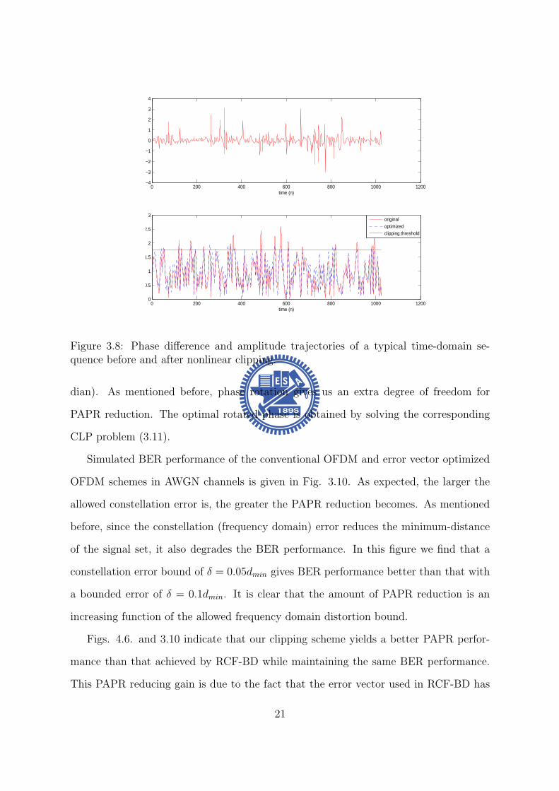
0 200 400 600 800 1000 12000
05
1
15
2
25
3
time (n)
ma
gn
itud
e
originaloptimizedclipping threshold
0 200 400 600 800 1000 1200minus4
minus3
minus2
minus1
0
1
2
3
4
time (n)
ph
ase
diff
ere
nce
(ra
dia
n)
Figure 38 Phase difference and amplitude trajectories of a typical time-domain se-quence before and after nonlinear clipping
dian) As mentioned before phase rotation gives us an extra degree of freedom for
PAPR reduction The optimal rotated phase is obtained by solving the corresponding
CLP problem (311)
Simulated BER performance of the conventional OFDM and error vector optimized
OFDM schemes in AWGN channels is given in Fig 310 As expected the larger the
allowed constellation error is the greater the PAPR reduction becomes As mentioned
before since the constellation (frequency domain) error reduces the minimum-distance
of the signal set it also degrades the BER performance In this figure we find that a
constellation error bound of δ = 005dmin gives BER performance better than that with
a bounded error of δ = 01dmin It is clear that the amount of PAPR reduction is an
increasing function of the allowed frequency domain distortion bound
Figs 46 and 310 indicate that our clipping scheme yields a better PAPR perfor-
mance than that achieved by RCF-BD while maintaining the same BER performance
This PAPR reducing gain is due to the fact that the error vector used in RCF-BD has
21
4 5 6 7 8 9 10 11 12 13
10minus4
10minus3
10minus2
10minus1
100
dB
CC
DF(
prob
(PA
PR
gt X
0))
Original P
av=10000
Proposed(δ=005dmin
) Pav
=10213
Proposed(δ=01dmin
) Pav
=09600
ACE Pav
=1084
RCFBD Pav
=10206
Figure 39 Effective PAPR gain for 16-QAM 256-carrier OFDM symbol with L=4 over-sampling for δ = 005dmin δ = 01dmin ACE RCFBD and separated coordinate PAPR
4 5 6 7 8 9 10 11 12 13
10minus3
10minus2
10minus1
SNR(dB)
Bit
Err
or R
ate
Original P
av=10000
δ=005dmin
Pav
=10213
δ=01dmin
Pav
=09600
ACE Pav
=1084
RCFBD Pav
=10206
Figure 310 BER of a 16-QAM and 256-carrier OFDM system
22
not been optimized
Although both ours and the ACE schemes use an optimization procedure to reduce
PAPR and our algorithm outperforms the ACE scheme by imposing BDrsquos A BD region
allows optimal modifications for distorted data points it enlarges the feasible set of linear
programming problem whence leads to a greater likelihood to find a solution with lower
PAPR
35 Chapter Summary
In this chapter we present a novel nonlinear clipping technique that extends the RCF-BD
and TR concepts to reduce the PAPR of OFDM signals We formulates the proposed
algorithm as one for solving a CLP problem The solution can be easily found by
following the established procedure The proposed approach does not have to modify
the receiver structure and needs not to send side information Moreover our algorithm
guarantees that the optimal error vector is obtained and the resulting PAPR value is
minimized under certain BD constraints The complexity of our algorithm can be greatly
reduced by if a fast algorithm to solve the corresponding CLP problem can be found
23
Chapter 4
Selective Mapping without SideInformation
41 Background
The basic idea of selective mapping (SLM) is to scramble an OFDM frame (symbol) by
a set of known sequences of the same length and select the scrambled (SLM-encoded)
one with the smallest PAPR for transmission
For uncorrelated SLM sequences the resulting SLM-encoded OFDM signals and
the corresponding PAPRrsquos will be uncorrelated Hence if the PAPR ratio for original
OFDM symbol has probability p of exceeding a certain level the probability for the
OFDM symbol using k SLM sequences is decreased to pk
There are three major design issues related to the SLM scheme namely encoder
and decoder complexities SLM sequences design and side information (SI) about the
scrambling sequence The designs presented in this chapter emphasize the latter two
concerns while the complexity is considered as a secondary issue We proposed a sequence
design which hides SI in each SLM sequence Since each sequence is distinguishable a
blind sequence detector can be used at receiver and data throughput is increased In
addition the implementation of proposed sequences are easy and memory usage is less
24
Figure 41 Original SLM encoder
42 System Model
Consider an OFDM system which transmits frequency domain OFDM symbol x =
[x(0) x(1) x(N minus 1)] in parallel using N sub-carriers fl l = 0 1 2 N minus 1 with
frequency spacing ∆f = 1T T being the symbol duration without the cyclic prefix (CP)
We assume that x(i) isin Q are M -PSK symbols whence Q is the set of constellation
points To reduce the resulting PAPR x is modified by one of sequences in the set
sk = [sk0 s
k1 s
kNminus1] k isin K where k is the sequence index and K can be regarded
as the set of selective mapping sequences
The SLM encoder chooses the encoded sequence y which resulting in a modified
sequence with the smallest PAPR value In other words neglecting the cyclic prefix the
transmitted frequency domain sequence is given by
y = si macr x i = arg minkisinK
PAPRIDFT (sk macr x) (41)
where macr represents the Hadamard product
25
After removing the prefix part and assuming perfect receiver synchronization the
received signal can be expressed as
r = hmacr y + w = hmacr si macr x + w (42)
where h = [h0 h1 middot middot middot hNminus1] is the frequency-domain channel response (CR) and w is
an zero mean white Gaussian noise vector with covariance σ2nI Since the operation macr
is commutative and slowasti macr r = hmacr x + wprime where wprime has the same statistical distribution
as w if h and the mapping sequence sk are known then
slowastk macr hlowast macr rmacr |h|minus2 = x + vdef= rprime (43)
where |h|minus2 = [|h0|minus2 |h1|minus2 middot middot middot |hNminus1|minus2] and v = [v0 v1 middot middot middot vNminus1] is a vector of
independent (but not identically) distributed Gaussian random variables Under this
circumstance the ML data detector is given by
x(skh)def= xk = D[rprime] (44)
where D[rprime] is the vector obtained by making componentwise MPSK decisions
Figure 42 SLM decoder proposed by Tellambura and Jayalath in [10]
26
The above discussion suggests that when the true CR is known the optimal detector
is
(x s) = arg minkisinK
L(r xk sk) (45)
where
L(r xk sk) =Nminus1sumn=0
||r[n]minus h[n]sk[n]xk[n]| |2 (46)
The pairwise error probability (PEP) P [(xi si) rarr (xk sk)|h] that the transmitted 2-
tuple (xi si) is erroneously decoded as (xk sk) is given by
P [(xi si) rarr (xk sk) |h] = PL(r xk sk) ge L(r xi si) (47)
Since
L(r xk sk) ge L(r xi si) (48)
or equivalently
Nminus1sumn=0
||r[n]minus h[n]sk[n]xk[n]||2 geNminus1sumn=0
||r[n]minus h[n]si[n]xi[n]||2 (49)
the PEP can be calculated as
P [(xi si) rarr (xk sk)|h]
=Nminus1prodn=0
Q
radic2 ||h[n]||2||si[n]xi[n]minus sk[n]xk[n]||2
No
(410)
Using the Chernoff bound
Q(x) le exp(minusx22) (411)
we obtain
P [(xi si) rarr (xk sk)|h]
leNminus1prodn=0
exp(minus||h[n]||2||si[n]xi[n]minus sk[n]xk[n]||2)
= exp
(minus
Nminus1sumn=0
||h[n]||2||si[n]xi[n]minus sk[n]xk[n]||2)
(412)
27
For AWGN or slow fading channels the upper-bound becomes
P [(xi si) rarr (xk sk)|ho] le exp(minush2w||sixi minus skxk||22) (413)
where hw = 1N0 (AWGN) or hw = minn h[n] (slow fading) Assuming equally signaling
and defining
Di = mink 6=ikisinK
||si macr xi minus sk macr xk||22 (414)
we express the average conditional symbol error probability (SEP) as
Ps(e) lesumiisinK
sum
kisinKminusiP (si)P [(xi si) rarr (xk sk)|ho]
le 1
|K|sumiisinK
exp(minush2Di) (415)
To minimize the average SEP the minimum Euclidean distance between si and any
other sequences Di should be maximized and which leads to an optimization problem
that could be formulated as follow
max Di
st si = [ejφi0 ejφi
1 ejφiNminus1 ] φi
n isin [0 2π)
sk = [ejφk0 ejφk
1 ejφkNminus1 ] φk
n isin [0 2π)
i isin K k isin Kminus i
where Di = mini 6=kikisinK
||si macr xi minus sk macr xk||22 (416)
For frequency selective fading channels with subcarrier spacing greater than the coherent
bandwidth h[n]rsquos can be modelled as identical and independent distributed random
variables hence we have [10]
P [(si xi) rarr (sk xk)|h]
(2Nminus1N )(SNR)minus2N
Nminus1prodn=0
|si[n]xi[n]minus sk[n]xk[n]|2(417)
whereNminus1prodn=0
|si[n]xi[n]minus sk[n]xk[n]|2 is the product distance between (si xi) and (sk xk)
28
43 Sequence design criteria
When M -PSK modulation is applied the expected value of relative Euclidean distance
between arbitrary two length-N SLM sequences of SLM decoder proposed in [10] can be
calculated as
Dlb =NM
π2
int πM
0
sinθ
2dθ
=4MN
π(1minus cos
π
2M) (418)
It can be proved that any polyphase sequences can have larger expected minimum pair-
wise distance than Dlb
By observing this fact two criteria have be found
bull 1)Every entry of a sequence should have distinct value to corresponding entry of
any other sequence That means a nonzero minimum distance shall be preserved
between the corresponding entry of arbitrary two sequences
bull 2)The magnitude of entries of SLM sequences is constant magnitude 1 Variable
magnitude might cause noise enhancement at receiver site
To accomplish the above two criteria unit circle shall be discretized into finite and equal-
spaced points and every entry of sequences has to take a value among all these discrete
points In addition the discretizing process ensures sequences become polyphase thus
generalized Euclidean distance Di is larger than Dlb After the discretizing process the
discrete total distance space is limited Our goal is to minimize the blind detection error
rate thus one more design criterion is introduced
bull 3)Because of the lack of prior knowledge of sequence selection each sequence has
the same probability of being selected By observing equation (415) A obvious
solution is to have all the pairwise distance to be equal Therefore Di should be
forced to be equal to Davg for all i
29
where Davg will be provided in section V we introduce group theory and use prime
number finite field to construct a set of sequences which could have equal pairwise
distance Proposed sequence design is optimal in the sense of discrete phase and is
easily constructed in the mean time memory requirement is less
For the next two sections we will first review the structure of the cyclic group G and
the definition of characters of finite field GF (p) and then use the knowledge of group
theory to construct a set of sequences which satisfies these three criteria
44 A Review on Group Theory
Let a be a generator of the finite cyclic group G ie G= 〈a〉 = an n isin Z Z being
the set of integers and denote the order of a by o(a) the cardinality of G by |G| We
immediately have |G| = |〈a〉| = o(a) Furthermore if |G| = p is prime then any non-
identity element of G is a generator ie G=〈g〉 and o(g) = p forall g isin Ge where e is
the identity of G
The set of all pth roots of unity in G Up(G) = a|o(a) = p a isin G is obviously a
cyclic group under the multiplication operation as forall a b isin Up(G) (ab)p = apbp = e rArrab isin Up(G) Now if G is the set of complex numbers C then e = 1 and Up(C) =
ej2πkp k = 1 2 middot middot middot p By denoting Wp = ej2πp we have Up(C) = 〈W kp 〉 for all k
An alternative statement is
Property 1 Define the listing vector generated by the seed g where g is a pth root of
unit then s(g) = (g0 g1 middot middot middot g(pminus1)) Two listing vectors generated by different seeds
are permuted version of each other ie
s(Wmp ) = s(W n
p )P forall m 6= n isin Z 0 (419)
where P is a permutation matrix
Note that s(W 0p ) = (1 1 middot middot middot 1) is the all-1 vector
30
45 Proposed SLM Sequence Design
In this section we will apply our knowledge of group characters to present proposed
sequence design for general M -PSK modulation and give an example of SLM sequences
under QPSK modulation
Since (414) is the combination of s and M -PSK data x x Data effect shall be
taken into consideration the ML decoder only count the relative distance from de-
SLM symbol to the nearest constellation point every decision region is equivalent in the
sense of calculating relative distance For M -PSK there are M decision boundaries and
every division is equivalent The proposed sequences design consists of two parts the
deterministic part sd and the data scrambling part sr The SLM sequences are obtained
by element-wise multiplying these two parts
s = sd macr sr (420)
The deterministic part is to have entries of sequences in one decision boundary to have
distinguishable value in the relative distance fashion Second the data scrambling part
is to randomly chooses one among all equivalent divisions to make encoded vector un-
correlated Since prime p cyclic group S(p) is chosen for SLM sequences each subgroup
of this cyclic group forms the deterministic part And the primitive element of S(p) is
W 1Mp Mp-th root of unity
The expression of sequence generated by element gk is
S(gk) = [s(g1k) s(g
2k) s(g
(pminus1)k )]
= [W kMpW
2kMp W
(pminus1)kMp ] (421)
is an Mxp matrix Each column of S(gk) is constructed by s(gnk )
Lemma 1 The pairwise distance between arbitrary two sequences which are con-
structed by different generated elements are equal D(S(gk1)S(gk2)) = D(S(gk1)S(gk3))
gk1 gk2 gk3 isin GF (p)
31
Proof Lemma1 can be easily shown by Preliminary 2 that each sequence has permu-
tation relation to any other sequence And the detail proof can be referred to Appendix
And the subtraction of arbitrary two sequences also has permutation relation There-
fore the pairwise distance is equal for arbitrary two sequences If distance of a complete
distance is defined as d then the minimum pairwise distance of arbitrary two sequences
is
D(S(gk1)S(gk2)) = d (422)
By Lemma 1 we can satisfy the third design criterion that pairwise distance of
arbitrary two sequences is equal
Lemma 2 The pairwise distance of any two sequences is equal to Davg
Proof Entries of all sequences with same index are a complete period of finite field
such that the total distance space for length-pminus 1 sequences within a decision region is
(p minus 1)d and the average distance is Davg = d It is easy to see that Davg is equal to
(422)
It is believed that the randomness in frequency domain is inversely proportional to
the PAPR value of the OFDM symbol Our goal is to have uncorrelated SLM sequences
Hence the data scrambling part of proposed SLM sequences has to be uncorrelated so
skr = [sk
r [1] skr [2] sk
r [pminus 1]] the data scrambling part of k-th sequence is generated by
probability mass function (pmf)
P (rn = s) =1
M s = 1 2 M n = 0 pminus 1 (423)
and each entry skr [n] is to indicate which division is used sk
r is corresponding to the
location of 1 in the row of the matrix Uk and others are zeros and we can have a indicator
vector by multiplying Uk with division matrix D = [ej2πM e
j2π(Mminus1)M ]T which consists of
representations of all decision boundaries of M-PSK Then the data scrambling sr part
of sequence can be represented as
skr = (UkD)T (424)
32
Figure 43 Distribution of generated element gk on unit circle
In the following we provide an example of p = 5 QPSK SLM sequences In QPSK
modulation the primitive element is W 14times5 = W 1
20 and the data effect phase vector
D = [W 04 W 1
4 W 24 W 3
4 ]T and the SLM sequence with generator element g1 is
S(g1) = [W 1times120 W 2times1
20 W 3times120 W 4times1
20 ]
The sequences with generator elements g2 g3 and g4 are
S(g2) = [W 1times220 W 2times2
20 W 3times220 W 4times2
20 ]
S(g3) = [W 1times320 W 2times3
20 W 3times320 W 4times3
20 ]
S(g4) = [W 1times420 W 2times4
20 W 3times420 W 4times4
20 ]
Then we have to choose one combination out of all possible sequences we use matrix
Uk k isin K to determine which expression is taken
Ex u1 = [1 3 2 2] implies that matrix U1 is
U1 =
1 0 0 00 0 1 00 1 0 00 1 0 0
33
and the corresponding sequence with generator element g1 is
s1 = [W 1times120 W 2times1
20 W 3times120 W 4times1
20 ]macr (U1D)T
= [W 1times120 W 2times1
20 W 24 W 3times1
20 W 14 W 4times1
20 W 14 ]
Sequence with generator element g2 with random vector u2 = [1 1 4 2] and the
matrix U2 is
U2 =
1 0 0 01 0 0 00 0 0 10 1 0 0
s2 = [W 1times220 W 2times2
20 W 3times220 W 4times2
20 ]macr (U2D)T
= [W 1times220 W 2times2
20 W 3times220 W 3
4 W 4times220 W 1
4 ]
Sequence with generator element g3 with random vector u3 = [3 1 2 4] and the
matrix U3 is
U3 =
0 0 1 01 0 0 00 1 0 00 0 0 1
s3 = [W 1times320 W 2times3
20 W 3times320 W 4times3
20 ]macr (U3D)T
= [W 1times320 W 3
4 W 2times320 W 3times3
20 W 14 W 4times3
20 W 34 ]
Sequence with generator element g4 with random vector u4 = [2 4 1 1] and the matrix
U4 is
U4 =
0 1 0 00 0 0 11 0 0 01 0 0 0
s4 = [W 1times420 W 2times4
20 W 3times420 W 4times4
20 ]macr (U4D)T
= [W 1times420 W 1
4 W 2times420 W 3
4 W 3times420 W 4times4
20 ]
Once we generate uk k = 1 pminus 1 from uniform distribution in (423) it is fixed and
should be known for both transmitter and receiver side
34
Figure 44 Block diagram of low complexity SLM encoder
46 Low Complexity SLM Encoder
An SLM scheme using U SLM sequences needs U IFFT operations to complete the
encoding Since proposed SLM sequences have good properties that sequences are com-
bined with deterministic term and data scrambling term the encoding procedure of SLM
using proposed SLM sequences can be simplified by using several circular shift units and
conversion blocks
For the modified encoder the deterministic part of our SLM sequence generated by
gk k = 1 pminus 1 is
S(gk) = [s(g1k) s(g
2k) s(g
(p)k )]
= [W kMpW
2kMp W
(p)kMp ] (425)
which is obtained by using an ktimesn0 = ktimes NLMp
circular shift in time domain where N is
number of sub-channel L is over-sampling factor M denotes M -PSK and p is chosen
for prime group
35
A time-frequency fourier transform pair has a updown sampling property that if
frequency domain sequence is repeated l times time domain pair is up-sampled l times
Ex [a b c d]-iquest[e f g h] is a frequency-time fourier pair where [a b c d] is frequency
domain sequence and [e f g h] is time domain pair of [a b c d] If [a b c d] is repeated
2 times and becomes [a b c d a b c d] time domain pair becomes [e 0 f 0 g 0 h 0]
We would take this property to implement the data scrambling part of proposed SLM
sequences First (p minus 1) 4-tuple sequences are randomly selected from scrambling set
1 jminus1minusj which has 256 combinations in total Each chosen sequence is repeated N4
times and becomes a length N sequence and in effect the corresponding time domain
vector tu will be N -tuple sequence with only 4 non-zero entries A sparse conversion
matrix Su can be formed as
Su = [t(0)u t(1)
u t(NLminus1)u ] (426)
where t(k)u is the circularly down-shifted version of the column vector t
(0)u by k elements
And sparse matrix operation has less complexity than IFFT and circular convolution
Frequency domain operation of proposed SLM sequences can be seen as circular
shift in time domain followed by circular convolution with a sparse signal Deterministic
part is a circular shift operation of data vector and scrambling part can be done by
convolution with a sparse signal Hence the encoding procedure is shown in fig 44
that frequency data vector is converted to time domain vector once Then each branch
represents a circular shift and a sparse conversion for corresponding SLM sequence
Since the proposed low complexity SLM encoder needs cyclic shift by ktimesn0 = ktimes NLMp
elements if ktimesn0 = ktimes NLMp
is not an integer a rounding cyclic shift ktimesn0 = bktimes NLMpc
takes place The integer cyclic shift can be done by left column cyclic shift of sparse
conversion matrix with d = bk times NLMpc columns then the new sparse conversion matrix
is defined as
Su = [t(0+d)u t(1+d)
u t(NLminus1+d)u ] (427)
36
Figure 45 Block diagram of modified low complexity SLM encoder
where d = bk times NLMpc defines the integer part of cyclic shift and t
(k)u is the circularly
down-shifted version of the column vector t(0)u by k elements
47 Simulation Results
In this section we provide some numerical results of our sequence design We consider
an OFDM system with 256 sub-carriers using QPSK modulation for the data carried
on N = 160 available subcarrier and it is operated under frequency selective channel
Since number of carriers is 160 group with order p = 17 shall be used Each subgroup
of S(gk) k = 1 p minus 1 forms sequence have to be repeated 10 times and uk is set
to be uncorrelated In addition there is an all one sequence s0 which means that data
encoded that sequence is equal to original data sequence x
In this chapter random generated sequences and chaotic sequence [12] are used to
compare with proposed sequence design Most widely used chaotic logistic map presented
37
6 7 8 9 10 11 12
10minus3
10minus2
10minus1
100
PAPR(dB)
CC
DF
originalproposedchaoticrandom
Figure 46 CCDF plot of PAPR performance of random sequences chaotic sequencesand proposed sequences design
in [12] is
xn+1 = rxn(1minus xn) 0 le xn lt 1 0 le r le 4 (428)
and r is called the bifurcation parameter The outcome of chaotic generator is distributed
in [0 1] with good correlation properties and the sequence is mapped from xn by the
following function
sc(n) = ej2πxn n = 1 2 160 (429)
Random generated sequences can be generated by mapping the random variable xn
which is uniformly distributed in [0 1] using the same mapping function in (429)
PAPR reduction performance has been proved to be proportional to the number of
SLM sequences as long as SLM seuqneces are uncorrelated ([9] and [13]) Fig 46 shows
that any sequence design which has the same number of uncorrelated sequences will have
the same PAPR performance However sequence index detection probability which is
called key error rate (KER) here can be improved by well-designed sequences and the
38
0 05 1 15 2
10minus5
10minus4
10minus3
10minus2
SNR
Pro
babi
lity
of in
dex
dete
ctio
n fa
ilure
proposedrandomchaotic
Figure 47 Probability of sequence index detection failure under frequency selectivechannel
45 50 55 60 65 700
01
02
03
04
05
06
07
08
09
1
Distance
CD
F
proposedrandomchaotic
Figure 48 Euclidean distance of random sequences chaotic sequences and proposedsequence design
39
0 5 10 15 2010
minus4
10minus3
10minus2
10minus1
100
SNR
KE
R
proposedAlsusaampYang
Figure 49 Probability of sequence index detection failure of proposed sequences andAlsusa and Yang sequences under frequency selective channel
5 6 7 8 9 10 11 1210
minus4
10minus3
10minus2
10minus1
100
PAPR(dB)
CC
DF
(PA
PR
gtη)
originalOne IFFT SLMSLM
Figure 410 CCDF of PAPR performance of original OFDM symbol low complexitySLM encoder and original SLM
40
proposed sequence design provides a promising coding gain that every sequence is NDavg
pminus1
far away from other sequences where Npminus1
have to be integer
Fig 48 shows the minimum pairwise distance of random generated sequences
chaotic sequences and proposed sequence design The minimum pairwise distance of
random generated and chaotic sequences are much less than the minimum pairwise dis-
tance of proposed sequence design As we can see in equation (415) that minimum
distance would dominate performance of blind decoder Fig 57 shows the trend of
this hypothesis and an asymptotically 03dB gain of proposed sequences to random and
chaotic sequences for signal-to-noise ratio (SNR) larger than 15dB Besides our design
criterion is to make all pairwise distance to be equal and fig 48 also shows that our
design satisfy this criterion
Alsusa and Yang [11] proposed an SLM sequences design in the proceedings of ICC
2006 Their design uses the locations of unmodified elements to identify different se-
quences thus receiver has only to detect the locations of unmodified block Their se-
quences have unmodified elements which is ej0 = 1 and other entries with magnitude 1
and phase [0 2π) distributed In fig 49 we can see that proposed design outperforms
Alsusa and Wangrsquos since their design only use part of sequence to identify each SLM
sequence Sequence pattern of proposed design spread through whole sequence hence
full degree of freedom is employed for sequence detection
The proposed low complexity SLM encoder has only one IFFT operation but it has
PAPR loss since sparse conversion block has correlation in frequency domain Although
low complexity SLM encoder has 08dB PAPR loss at CCDF = 104 in fig 410 the
complexity is decreased from O(LNlog(LN)) to O(4LN) While using SLM to be PAPR
reduction scheme the SLM sequences have to be stored in both transmitter and receiver
sides to do the encoding and decoding Only the data scrambling vectors uk k =
1 p minus 1 have to be stored for using proposed sequences It costs log2 M bits of
memory for one entry to store the vectors uk In the case of QPSK 2 bits memory for
41
one element in sequence is needed
The SLM scheme is simple quick and effective in the sense of reducing PAPR
however SLM is not recommended in several latest released standard proposals due to
its sequence index detection failure Since we can achieve the sequence detection failure
probability Pe = 10minus5 at 2dB SNR which is acceptable in wireless communication SLM
should be reconsidered to be a main PAPR reduction scheme
48 Chapter Summary
In this chapter a novel selective mapping sequence design is proposed that minimum
pairwise distance of arbitrary two sequences is equal It provides the system a bound
of minimum distance Davg between sequences which has a guaranteed coding gain that
every codeword is separated at least Davg apart And simulation results show that pro-
posed design scheme has more than 03dB gain on sequence index detection probability
and it reaches detection failure probability Pe = 10minus5 at SNR = 2dB which is robust
enough for wireless communication
42
Chapter 5
Selective Mapping with EmbeddedSide Information
In this chapter we present an improved non-blind SLM-based PAPR reduction
scheme which uses SLM as the main PAPR reduction mechanism side information (SI)
is transmitted within the same OFDM symbol The embedded SI is further exploited
to reduce PAPR and enhance SI detection performance
51 System Model
Figure 51 Bandwidth utilization of proposed scheme
We consider an OFDM system with N in-band sub-carriers which can be divided
into data sub-carriers set Sd = ld0 ldDminus1 with cardinality D and SI sub-carriers set
SI = lI0 lIPminus1 with cardinality P X = [X[ld0 ] X[ldDminus1
]] is data vector which
is modulated by quadrature amplitude modulation (QAM) SLM sequence denotes as
suk = [Sk[ld0 ] su[ldDminus1]] and each entry is uniformly distributed in [0 2π) and u isin K
with cardinality |K| = U Given the original OFDM symbol U alternative representa-
43
tions of signal candidates Xu = X macr su can be obtained by element-wise multiplying
the original OFDM symbol with different SLM sequences Furthermore the SI of SLM
sequence which is the index of the used sequence is modulated onto sub-carriers of
SI The SI vector denotes as Ausi = [Au
si[lI0 ] Ausi[lIPminus1
] The entire frequency domain
OFDM symbol can be represented as Xu = [Xu[ld0 ] Xu[ldDminus1] Au
si[lI0 ] Ausi[lIPminus1
]]
which is the scrambled data plus embedded SI
Figure 52 Original SLM encoder with embedded SI
Our scheme consists of two stages In the first stage we choose the one with low-
est PAPR among U different candidate SLM-encoded OFDM symbols Second stage
adopts two different algorithms to reduce PAPR by adjusting the SI symbols meanwhile
having better SI detection error protection The first algorithm employs active constel-
lation extension (ACE) [4] to adjust SI and the second algorithm uses POCS [15] for SI
adjustment
This chapter is organized as follow Section II consider the encoding and insertion of
SI ACE and POCS are introduced in section III Simulation results and brief conclusion
are provided in section IV and V
44
52 Encoding Side Information and Insertion
521 Insertion of the Side Information
The main concern of using SLM scheme is the correctness of SI and channel coding
techniques are involved for having better error protection Original SI bits are log2(U)
and the encoded SI bits are log2(n) if (nk) linear block code is used And the number of
SI sub-carriers can be determined by the ratio of encoded SI bits and modulation type
of SI sub-carriers
P = d n
log2(M)e (51)
where M is the number of constellation points of the modulation type being used The
vector representing SI symbols is generated by a mapping S which maps the index u to
a vector of QAM symbol Ausi
S u rarr Ausi u = 1 U (52)
and the index of Ausi can be seen in figure 51
522 Estimation of Side Information
At the receiver after applying discrete fourier transform (DFT) and zero-forcing equal-
ization the received OFDM frequency symbol is denoted as Y and SI vector is denoted
as Ysi The noisy vector Ysi consists of signal apart Ausi and noise part with variance
σ2n|Hn|2
Maximum likelihood (ML) estimation is applied for decoding sequence index u The
estimate u can be obtained by
u = arg maxu=1U
PrYsi|Ausi
= arg maxu=1U
Pminus1prodn=0
PrYsi[n]|Ausi[n]
= arg minu=1U
Pminus1sumn=0
|Ysi[n]minus Ausi[n]|2
σ2n|Hn|2
(53)
45
In order to execute the ML estimator channel state information |Hn|2 and noise variance
σ2n have to be known
523 Encoding Scheme of SI
Several earlier approaches [16] use (74) Hamming code to encode SI
Example The number of SLM sequences in the set K is 16 so we can use the 3-bit
representation (0 0 0 0) (0 0 0 1) (1 1 1 1) for the sequence index Using the
Hamming code with generator matrix G given by
G =
1 1 0 11 0 1 11 0 0 00 1 1 10 1 0 00 0 1 00 0 0 1
(54)
we obtain 7-bit encoded vectors by c = uG
Since ML estimation is used for decoding sequence index only generator matrix or
generator polynomial is needed for transmitter and receiver
For proposed scheme BCH code is involved for a better error protection capability
One of the advantages of BCH is easy implementation that shift register can be used
to generate encoding sequence Polynomial representation for information bits and gen-
erator polynomial is needed For BCH(3167) information bits should be written as
XX + 1X5 + X4 + X3 + X2 + X + 1 and the generator polynomial is
g(X) = X25+X24+X21+X19+X18+X16+X15+X14+X13+X11+X9+X5+X2+X+1
(55)
The resulting encoded sequence is denoted as cu = [cu[0] cu[31minus 1]]
As we have no posterior information of the peak locations of time domain SLM en-
coded signal the PAPR of SI vector should be minimized If the number of SI bits
(log2(U)) are less than that of the input information bits (k) there is extra degrees of
freedom can be used to find SI with smaller PAPR In proposed scheme the number
46
of SLM sequences is U = 8 and the (3167) BCH code is used to encode SI Hence
we choose the eighth lowest PAPR sequences among all the possible encoded BCH se-
quences It shall be mentioned that this process shall include the modulation of encoded
bits onto SI sub-carriers and the results will be different if the modulation scheme is
different
53 Side Information Adjustment Algorithm
Our scheme is a two-stage algorithm (see Fig 52) whose first stage involves the insertion
of SI and the selection among possible candidate SLM-encoded vectors This section
discusses the second stage operations where clipping is employed while frequency domain
feasible set is defined on SI sub-carries only There are two algorithm being adopted
531 Problem Formulation
The effect of inserted SI can be viewed as a time domain signal au = IDFTAusi which
is contributed by SI only plus the time domain SLM encoded signal x = IDFTXAnd the addition of the two signals should be minimized below threshold η This can
be formed as an optimization problem
min η
st
||x||infin le η
where au = IDFTAusi + esi
x = IDFTX
||x||infin = ||x + au||infinin variables esi isin CNL η isin R
(56)
47
SLM encoded signal x = IDFTX shall not be changed to maintain the bit error rate
(BER) performance thus only SI part au can be modified to reduce PAPR There are
two algorithms active constellation extension (ACE) and projection onto complex set
(POCS) can be adopted and they will be introduced in the following two subsections
532 Active Constellation Extension for SI Adjustment
Figure 53 Extended region of QPSK denoted as F
The encoded SI vector is binary and quadrature phase shift keying (QPSK) is used
as the mapping S from sequence index u to SI vector Ausi Thus the number of SI sub-
carriers can be determined by d nlog2(4)
e ACE algorithm is used to modified Ausi within
the frequency domain constraint set By doing so the PAPR of the modified symbol
will be reduced and as the constellation points are further apart from decision boundary
the detection error protection is improved Here we define frequency domain extended
region as feasible set F for modified SI symbol in figure 53
48
The new PAPR reduction problem can be written as follow
min η
st
||x||infin le η
where au = IDFTAusi + esi
x = IDFTX
||x||infin = ||x + au||infinin variables esi isin CNL η isin R
(57)
One simple way is iterative clipping and filtering that the time domain signal is first
clipped and followed by restoring data vector back to its original value of the SLM
encoder output and projecting the SI symbol back to frequency domain feasible set F
The iterative signal update can be written as
xi+1 = xi + microei (58)
where i is the iteration number and xi is the time domain iterative signal The clipping
rule is
Rex[n] =
Rexi[n] |Rexi[n]| le η
η |Rexi[n]| gt η
Imx[n] =
Imxi[n] |Imxi[n]| le η
η |Imxi[n]| gt η
x = Rex+ j lowast Imx (59)
Thus the time domain error vector is eiclip = x minus xi and the frequency domain error
vector can be obtained by Eiclip = DFTei
clip And the frequency update signal Ei has
to satisfy several predefined frequency domain constraint that error at data part should
be zero Ei[n] = 0 n = ld0 ldDminus1and error at SI has to be within frequency feasible set
Ei[n] =
Ei[n] = Eclip[n] n = lI0 lIPminus1
if Eclip[n] isin E
Ei[n] = proj(Eclip[n]E) n = lI0 lIPminus1 otherwise
49
where proj(aA) is the function that project a onto the nearest point in set A And the
time domain update signal is ei = IDFTEiJones [4] introduces smart gradient projection (SGP) algorithm that step size micro is
updated for every iteration The ACE-SGP algorithm is list as follow
Step 1 InitializationSet iteration number i = 0 and clipping threshold η
Step 2 x is obtained by clipping xi with threshold ηCompute the update signal of ei[n] by ei
clip = xminus xiand compute projection of ei[n] along xi[n] for every sample
eproj[n] = ltxi[n]lowasteilowast[n]|xi[n]| n = 0 N minus 1
Step 3 Given xi compute maximum magnitude E and thecorresponding sample position nmax for iteration iP = max
n|xi[n]|
nmax = arg maxn|xi[n]|
Step 4 Compute approximate balancing for eproj[n] gt 0
micro[n] = Pminus|xi[n]|eproj [n]minuseproj [nmax]
Choose the minimum micro as step size
Step 5 Update the signal xi+1 = xi + microei with variable step size micro
Step 6 Iteratively execute from step 2 to step 5If micro is negative stop algorithm
Table 51 Active constellation extension with smart gradient projection algorithm
Usually the SGP algorithm converges to a near-optimal solution within 5 iterations As
we can see the feasible set of ACE algorithm is only in a quadrant which means the
phase of SI symbol can only be changed from minusπ4
to π4 In the following we come up
with an idea to have phase of SI symbol to change from 0 to 2π and the phase degree
of freedom is employed And this is introduced next for AM modulation of SI vector
50
533 Projection onto Complex Set for SI Adjustment
Since phase degree of freedom of SI symbol is concerned SI symbol should be freely
moved from 0 to 2π and carry information on amplitude Thus the mapping rule
S u rarr Ausi is amplitude modulation which maps 0 onto unit circle and 1 onto circle
with radius 2 And the number of SI sub-carriers can be determined by d nlog2(2)
e = n
The mapping S is
Ausi[i] =
1 middot ejθ[i] if cu[i] = 0
2 middot ejθ[i] if cu[i] = 1
where phase θ[i] i = 0 n minus 1 is uniformly distributed in [0 2π) The frequency
domain feasible set C is defined in figure 54
Figure 54 Amplitude modulation for POCS algorithm
51
And the PAPR reduction problem becomes
min η
st
||x||infin le η
|Ausi[i]| le 1 if cu[i] = 0
|Ausi[i]| ge 2 if cu[i] = 1
where au = IDFTAusi + esi
x = IDFTX
||x||infin = ||x + au||infinin variables esi isin CNL η isin R
(510)
As we can see in fig 54 that the outer circle is not a convex set and it can not be
solved by any convex optimization tool thus projection onto complex set algorithm is a
sub-optimal algorithm to take place The following is POCS algorithm
Step 1 Initialization vector x is IDFT of X
Step 2 Enforce x to satisfy the pre-defined threshold ηIf the modified x satisfies x = x then terminatedOtherwise go to step 3
Step 3 Perform DFT to x to obtain X and
restore data part [X[ld0 ] X[ldDminus1]] = X and
project SI part [proj(X[lI0 ]C) proj(X[lIPminus1]C)]
to the closest point in C
Step 4 Iteratively execute step 2 and step 3 until there is no PAPRreduction gain or PAPR is small enough
Table 52 Projection onto Complex Set algorithm
52
Next section simulation results are provided and modified SI symbols by ACE algorithm
and POCS algorithm is observed
54 Numerical Results
In this section we provide several numerical results to show the key error rate (KER)
which is the SI detection probability and CCDF of PAPR performance Also the figures
of modified frequency domain SI is provided For different SI modulation we have
different settings to make them comparable For QPSK modulation of SI an OFDM
symbol with 256 sub-carriers is considered and 152 in-band sub-carriers are further
divided into 136 data sub-carriers and 16 SI sub-carriers However for AM modulation
of SI an OFDM symbol with 512 sub-carriers is considered and 304 in-band sub-carriers
are further divided into 273 data sub-carriers and 31 SI sub-carriers Thus the ratio of
SI sub-carriers and total sub-carriers are equal for both system The number of SLM
sequences is 8 and BCH(3167) is used for SI encoding The system is simulated under
frequency selective channel for error rate performance
First we would like to show the modified SI do locate inside the defined frequency
domain constraint set In fig 55 the modified SI do stay within the extended region
and the red cross stands for original QPSK constellation points and blue circle means
the modified symbol In fig 56 r = 1 red circle stands for the amplitude modulation
for information bit 0 and r = 2 red circle stands for the amplitude modulation for
information bit 1 The symbols do stay within the constraint set with random phase
For both scheme symbols move opposite direction toward decision boundary thus SI
detection probability is improved
The simulated KER and PAPR performance are provided in fig 57 fig 46 In Fig
46 the POCS algorithm and ACE algorithm can further reduce PAPR than orignal
SLM and SLM with inserted SI POCS outperform ACE because POCS has more phase
degree of freedom than ACE As we can see from the constraint set of ACE (Fig 53)
53
minus2 minus15 minus1 minus05 0 05 1 15 2minus2
minus15
minus1
minus05
0
05
1
15
modified SIQPSK points
Figure 55 Location of modified SI symbol using active constellation extension (ACE)algorithm
minus2 minus15 minus1 minus05 0 05 1 15 2minus25
minus2
minus15
minus1
minus05
0
05
1
15
2
25
Modified SIr=1 circler=2 circle
Figure 56 Location of modified SI symbol using projection onto complex set (POCS)algorithm
54
minus10 minus5 0 5 1010
minus5
10minus4
10minus3
10minus2
10minus1
100
SNR(dB)
KE
R
ACEPOCS
Figure 57 Key error rate for ACE and POCS schemes
6 7 8 9 10 11 1210
minus4
10minus3
10minus2
10minus1
100
PAPR(dB)
CC
DF
(PA
PR
gtPA
PR 0)
data onlySLMSLM data with embbeded SIoptimized SI (ACE)
Figure 58 CCDF of PAPR of original SLM SLM embedded SI and SLM with modifiedSI (ACE)
55
5 6 7 8 9 10 11 1210
minus4
10minus3
10minus2
10minus1
100
PAPR(dB)
CC
DF
(PA
PR
gtPA
PR 0)
data onlySLMSLM data with embbeded SIoptimized SI (POCS)
Figure 59 CCDF of PAPR of original SLM SLM embedded SI and SLM with modifiedSI (POCS)
the phase degree of freedom for every symbol is [minusπ4 π4] however for constraint set
of POCs (Fig 54) every symbol has phase degree of freedom from [0 2π) It is believed
that phase degree of freedom is much more effective than magnitude degree of freedom
in the sense of PAPR reduction
Fig 57 shows that there is a 3dB KER performance gap between ACE and POCS
schemes because the minimum distance of QPSK constellation is twice the minimum
distance of Amplitude modulation and also ML symbol-wise estimation is used Despite
of the 3dB gap the KER decreases to 10minus4 at SNR=5 (ACE) and SNR=8 (POCS) Such
performance is robust enough for wireless communication
55 Chapter Summary
In this chapter we provide another option for SI transmission to receiver that SI is
inserted within the same OFDM symbol Two algorithms are proposed to modified
56
SI to further reduce PAPR Simulation results show that with second stage cascaded
PAPR reduction outperforms than original SLM and it reaches KER Pe = 10minus4 at 5dB
and 8dB SNR for ACE and POCS respectively
57
Chapter 6
Conclusion
61 Summary of Contributions
Peak-to-average power ratio is one of the most critical design concerns for OFDM sys-
tems We have presented two new PAPR reduction approaches and a SLM sequence
design in this thesis
We first proposed a nonlinear clipping method with hybrid frequency domain con-
straints to obtain a larger feasible set The PAPR reduction problem is formulated as
a standard linear programming (LP) form which can then be solved by well-developed
LP tools to obtain the optimal clipping threshold and optimal clipped OFDM symbols
A novel SLM sequences design aimed to offer improved blind (non-side-information
aided) detection performance is proposed Our design renders a simple hardware real-
ization with less memory requirement
Our third contribution has to do with side information transmission in an SLM sys-
tem Our scheme inserts the SI in the same OFDM symbol By adjusting SI we further
reduce the PAPR ACE and POCS algorithms are adopted to modify the transmitted
SI
58
62 Some Future Works
The complexity of the LP solution presented is still high for real-time implementation
Better algorithms are needed to reduce the overall the complexity of solving the target
LP problem Finding a mathematical connection between error vector magnitude and
bit error rate performance remains unsolved If such a relationship can be established
then one can solve the PAPR reduction and BER minimization simultaneously
For the SLM-aided OFDM system we believe that both the associated blind de-
coder complexity and performance can be further improved Analysis of the exact blind
sequence detection probability and the corresponding BER performance is also desired
For the proposed SI-aided scheme to become practical we have to reduce the re-
quired number of SI sub-carriers to improve bandwidth efficiency Further complexity
suggestions are always welcome Linear system with sparse solution optimization prob-
lem might be needed to find a near-optimal solution for projection onto convex set
algorithm
59
Appendix
In this Appendix we continue on proving that minimum pairwise distance of any two
arbitrary sequences are equal Here we have three arbitrary sequences
D(S(g1)) = D([W k1MpW
2k1Mp W
(pminus1)k1
Mp ]otimesD) (61)
= [W(k1 mod p)Mp W
(2k1 mod p)Mp W
((pminus1)k1 mod p)Mp ] (62)
k1 isin [0 pminus 1] isin Z
D(S(g2)) = D([W k2MpW
2k2Mp W
(pminus1)k2
Mp ]otimesD) (63)
= [W(k2 mod p)Mp W
(2k2 mod p)Mp W
((pminus1)k2 mod p)Mp ] (64)
k2 isin [0 pminus 1]minus k1 isin Z
D(S(g3)) = D([W k3MpW
2k3Mp W
(pminus1)k3
Mp ]otimesD) (65)
= [W(k3 mod p)Mp W
(2k3 mod p)Mp W
((pminus1)k3 mod p)Mp ] (66)
k3 isin [0 pminus 1]minus k1 k2 isin Z
where D(middot) is the relative distance function of sequence to the nearest constellation
points Since relative distance to constellation points is considered equation (61)(63)(65)
and equation (62)(64)(66) can be seen as to calculate relative distance of those expres-
sion to nearest constellation points
We now use predefined distance function D(x1x2) to calculate the pairwise relative
distance between this three sequences The relative distance between S(g1) and S(g2)
60
can be calculate as
D(S(g1)S(g2)) =
pminus1sumn=0
min |W k1nMp otimesDminusW k2n
Mp otimesD|2 (67)
=
pminus1sumn=0
|W (k1n mod p))Mp minusW
(k2n mod p)Mp |2 (68)
=
pminus1sumn=0
|1minusW((k2minusk1)n mod p)Mp |2 (69)
In (67)ndash(68) we use (mod p) to replace (otimesD) as in (61) and (62)
The relative distance between S(g1) and S(g3) can be calculate as
D(S(g1)S(g3)) =
pminus1sumn=0
min |W k1nMp otimesDminusW k3n
Mp otimesD|2 (610)
=
pminus1sumn=0
|W (k1n mod p)Mp minusW
(k3n mod p)Mp |2 (611)
=
pminus1sumn=0
|1minusW((k3minusk1)n mod p)Mp |2 (612)
(610) is simplified to be (611) in the same sense of (67) and (68)
However s(gnk ) = (W kn
Mp) n = 1 pminus 1 is character vector of group S(p) Since p
is odd prime number it can be shown by () that
s(gn1 minus gn
2 ) = Ps(gn1 minus gn
3 ) (613)
where P is permutation matrix
We can apply this relation to the distance function D(x1x2) since x1 and x2 have
the relation in (613) The corresponding distance character of (69) and (612) are
S21 = |1minusW((k2minusk1)n mod p)Mp | n = 1 pminus 1
S31 = |1minusW((k3minusk1)n mod p)Mp | n = 1 pminus 1
will also satisfy the same relation that
S21 = PS31
61
where P is permutation matrix Therefore
pminus1sumn=0
|1minusW((k3minusk1)n mod p)Mp |2 =
pminus1sumn=0
|1minusW((k2minusk1)n mod p)Mp |2
D(S(g1)S(g2)) = D(S(g1)S(g3)) (614)
and
D(S(g1)S(g2)) = D(S(g2)S(g3))
D(S(g1)S(g2)) = d
D(S(g2)S(g3)) = d (615)
(616)
which prove that arbitrary two sequences of proposed design have equal pairwise dis-
tance
62
Bibliography
[1] T Jiang and Y Wu ldquoAn overview Peak-to-average power ratio reduction tech-
niques for OFDM signalsrdquo Broadcasting IEEE Transactions on Vol 54 Issue 2
Page(s)257 - 268 June 2008
[2] AE Jones TA Wilkinson and SK Barton ldquoBlock coding scheme for reduction of
peak to mean envelope power ratio of multicarrier transmission schemesrdquo Electron
Lett Vol 30 Issue 25 Page(s)2098-2099 8 Dec 1994
[3] ADS Jayalath and C Tellambura ldquoReducing the peak-to-average power ratio of
orthogonal frequency division multiplexing signal through bit or symbol interleavingrdquo
Electron Lett Vol 36 Issue 13 Page(s)1161-1163 22 June 2000
[4] B S Krongold and D L Jones ldquoPAR reduction in OFDM via active constellation
extensionrdquo Broadcasting IEEE Transactions on Vol49 No3 pp258-268 Sept
2003
[5] S K Deng and M C Lin ldquoRecursive clipping and filtering with bounded distortion
for PAR reductionrdquo Communications IEEE Transactions on Vol55 No1 pp227-
230 Jan 2007
[6] S Janaaththanan C Kasparis and B G Evans ldquoA gradient based algorithm for
PAPR reduction of OFDM using tone reservationrdquo Vehicular Technology Confer-
ence 2008 VTC Spring 2008 IEEE Page(s)2977 - 2980 11-14 May 2008
63
[7] J Armstrong ldquoPeak-to-average power ratio reduction for OFDM by reapeted clipping
and frequency domain filteringrdquo Electron Lett vol38 pp 246-247 Feb 2002
[8] J Tellado and J M Cioffi ldquoPAR reduction in multicarrier transmission systemsrdquo
ANSI Document T1E14 Technical Subcommittee 2008
[9] RW Bauml RFH Fischer and JB Huber ldquoReducing the peak-to-average power
ratio of multicarrier modulation by selected mappingrdquo Electron Lett Vol 32 no
22 pp 2056-2057 Oct 1996
[10] ADS Jayalath and C Tellambura ldquoSLM and PTS peak-power reduction of OFDM
signals without side informationrdquo Wireless Comm Vol 4 no 5 pp 2006-2013 Sept
2005
[11] E Alsusa and L Yang ldquoNovel redundancy-free and SER-improved selective map-
ping technique with coded phase sequences for PAPR reduction in OFDM systemsrdquo
International Communication Conference 2006 ICC 2006rdquo Vol 4 no 5 pp 2887-
2892 June 2006
[12] G Heidari-Bateni CD McGillem ldquoChaotic sequences for spread spectrum an
alternative to PN-sequencesrdquordquo Proceedings of 1992 IEEE InternationalConference
on Selected Topics in Wireless Communicatiom Vancouver Canada pp437-440
25-26 June 1992
[13] K Bae EJ Powers ldquoDistribution of envelope power using selected mapping in
OFDM systems with nonlinearityrdquo Acoustics Speech and Signal Processing 2008
ICASSP 2008 IEEE International Conference on pp3065-3068 Mar 31-Apr 4
2008
[14] RA Scholtz and LR Welch ldquoGroup characters Sequences with good correlation
propertiesrdquo IEEE Trans Inform Theoty vol 24 no 5 pp 537 - 545 Sep 1978
64
[15] R K Martin and M Haker ldquoReduction of peak-to-average power ratio in transform
domain communication systemsrdquoIEEE trans Wireless Comm vol8 no9 pp4400-
4405 Sept 2009
[16] ADS Jayalath C Tellambura ldquoPeak-to-average power ratio reduction of an
OFDM signal using data permutation with embedded side informationrdquo Circuits and
Systems 2001 ISCAS 2001 The 2001 IEEE International Symposium on vol4
pp562-565 6-9 May 2001
[17] D Divsalar MK Simon ldquoTrellis coded modulation for 4800-9600 bitss trans-
mission over a fading mobile satellite channelrdquo Selected Areas in Communications
vol5 no2 pp 162- 175 Feb 1987
[18] D Divsalar MK Simon ldquoThe design of trellis coded MPSK for fading chan-
nels performance criteriardquo Communications IEEE Transactions on vol36 no9
pp1004-1012 Sept 1988
65
66
作 者 簡 歷
董原豪台北市人1986 年生 台北市立成功高級中學 200109~200406
國立交通大學電信工程學系 200409~200806
國立交通大學電信工程研究所系統組 200809~201006
Graduate Course
1 Random Process
2 Digital Signal Processing
3 Digital Communications
4 Coding Theory
5 Information Theory
6 Detection and Estimation Theory
7 Matrix Computations
8 Computer Communication Networks
9 Wireless Communications
- 論文封面pdf
- 中文摘要pdf
- 英文摘要pdf
- 誌 謝pdf
- mainpdf
- 作 者 簡 歷pdf
-
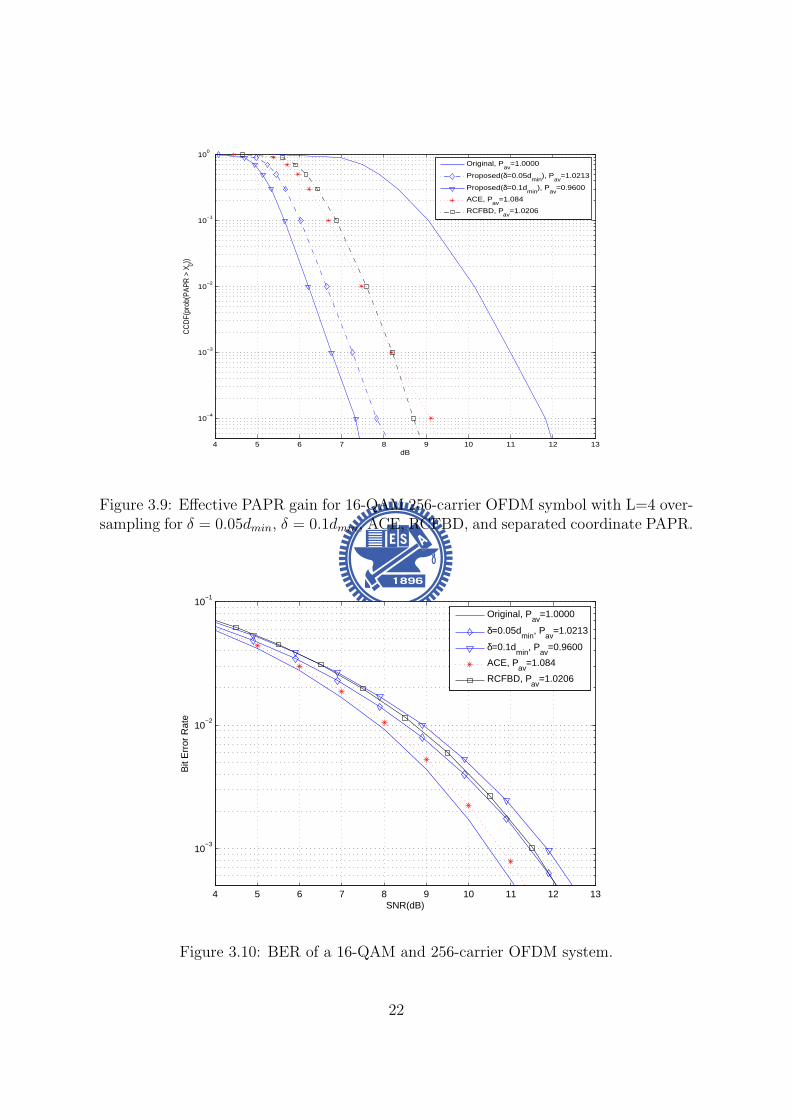
4 5 6 7 8 9 10 11 12 13
10minus4
10minus3
10minus2
10minus1
100
dB
CC
DF(
prob
(PA
PR
gt X
0))
Original P
av=10000
Proposed(δ=005dmin
) Pav
=10213
Proposed(δ=01dmin
) Pav
=09600
ACE Pav
=1084
RCFBD Pav
=10206
Figure 39 Effective PAPR gain for 16-QAM 256-carrier OFDM symbol with L=4 over-sampling for δ = 005dmin δ = 01dmin ACE RCFBD and separated coordinate PAPR
4 5 6 7 8 9 10 11 12 13
10minus3
10minus2
10minus1
SNR(dB)
Bit
Err
or R
ate
Original P
av=10000
δ=005dmin
Pav
=10213
δ=01dmin
Pav
=09600
ACE Pav
=1084
RCFBD Pav
=10206
Figure 310 BER of a 16-QAM and 256-carrier OFDM system
22
not been optimized
Although both ours and the ACE schemes use an optimization procedure to reduce
PAPR and our algorithm outperforms the ACE scheme by imposing BDrsquos A BD region
allows optimal modifications for distorted data points it enlarges the feasible set of linear
programming problem whence leads to a greater likelihood to find a solution with lower
PAPR
35 Chapter Summary
In this chapter we present a novel nonlinear clipping technique that extends the RCF-BD
and TR concepts to reduce the PAPR of OFDM signals We formulates the proposed
algorithm as one for solving a CLP problem The solution can be easily found by
following the established procedure The proposed approach does not have to modify
the receiver structure and needs not to send side information Moreover our algorithm
guarantees that the optimal error vector is obtained and the resulting PAPR value is
minimized under certain BD constraints The complexity of our algorithm can be greatly
reduced by if a fast algorithm to solve the corresponding CLP problem can be found
23
Chapter 4
Selective Mapping without SideInformation
41 Background
The basic idea of selective mapping (SLM) is to scramble an OFDM frame (symbol) by
a set of known sequences of the same length and select the scrambled (SLM-encoded)
one with the smallest PAPR for transmission
For uncorrelated SLM sequences the resulting SLM-encoded OFDM signals and
the corresponding PAPRrsquos will be uncorrelated Hence if the PAPR ratio for original
OFDM symbol has probability p of exceeding a certain level the probability for the
OFDM symbol using k SLM sequences is decreased to pk
There are three major design issues related to the SLM scheme namely encoder
and decoder complexities SLM sequences design and side information (SI) about the
scrambling sequence The designs presented in this chapter emphasize the latter two
concerns while the complexity is considered as a secondary issue We proposed a sequence
design which hides SI in each SLM sequence Since each sequence is distinguishable a
blind sequence detector can be used at receiver and data throughput is increased In
addition the implementation of proposed sequences are easy and memory usage is less
24
Figure 41 Original SLM encoder
42 System Model
Consider an OFDM system which transmits frequency domain OFDM symbol x =
[x(0) x(1) x(N minus 1)] in parallel using N sub-carriers fl l = 0 1 2 N minus 1 with
frequency spacing ∆f = 1T T being the symbol duration without the cyclic prefix (CP)
We assume that x(i) isin Q are M -PSK symbols whence Q is the set of constellation
points To reduce the resulting PAPR x is modified by one of sequences in the set
sk = [sk0 s
k1 s
kNminus1] k isin K where k is the sequence index and K can be regarded
as the set of selective mapping sequences
The SLM encoder chooses the encoded sequence y which resulting in a modified
sequence with the smallest PAPR value In other words neglecting the cyclic prefix the
transmitted frequency domain sequence is given by
y = si macr x i = arg minkisinK
PAPRIDFT (sk macr x) (41)
where macr represents the Hadamard product
25
After removing the prefix part and assuming perfect receiver synchronization the
received signal can be expressed as
r = hmacr y + w = hmacr si macr x + w (42)
where h = [h0 h1 middot middot middot hNminus1] is the frequency-domain channel response (CR) and w is
an zero mean white Gaussian noise vector with covariance σ2nI Since the operation macr
is commutative and slowasti macr r = hmacr x + wprime where wprime has the same statistical distribution
as w if h and the mapping sequence sk are known then
slowastk macr hlowast macr rmacr |h|minus2 = x + vdef= rprime (43)
where |h|minus2 = [|h0|minus2 |h1|minus2 middot middot middot |hNminus1|minus2] and v = [v0 v1 middot middot middot vNminus1] is a vector of
independent (but not identically) distributed Gaussian random variables Under this
circumstance the ML data detector is given by
x(skh)def= xk = D[rprime] (44)
where D[rprime] is the vector obtained by making componentwise MPSK decisions
Figure 42 SLM decoder proposed by Tellambura and Jayalath in [10]
26
The above discussion suggests that when the true CR is known the optimal detector
is
(x s) = arg minkisinK
L(r xk sk) (45)
where
L(r xk sk) =Nminus1sumn=0
||r[n]minus h[n]sk[n]xk[n]| |2 (46)
The pairwise error probability (PEP) P [(xi si) rarr (xk sk)|h] that the transmitted 2-
tuple (xi si) is erroneously decoded as (xk sk) is given by
P [(xi si) rarr (xk sk) |h] = PL(r xk sk) ge L(r xi si) (47)
Since
L(r xk sk) ge L(r xi si) (48)
or equivalently
Nminus1sumn=0
||r[n]minus h[n]sk[n]xk[n]||2 geNminus1sumn=0
||r[n]minus h[n]si[n]xi[n]||2 (49)
the PEP can be calculated as
P [(xi si) rarr (xk sk)|h]
=Nminus1prodn=0
Q
radic2 ||h[n]||2||si[n]xi[n]minus sk[n]xk[n]||2
No
(410)
Using the Chernoff bound
Q(x) le exp(minusx22) (411)
we obtain
P [(xi si) rarr (xk sk)|h]
leNminus1prodn=0
exp(minus||h[n]||2||si[n]xi[n]minus sk[n]xk[n]||2)
= exp
(minus
Nminus1sumn=0
||h[n]||2||si[n]xi[n]minus sk[n]xk[n]||2)
(412)
27
For AWGN or slow fading channels the upper-bound becomes
P [(xi si) rarr (xk sk)|ho] le exp(minush2w||sixi minus skxk||22) (413)
where hw = 1N0 (AWGN) or hw = minn h[n] (slow fading) Assuming equally signaling
and defining
Di = mink 6=ikisinK
||si macr xi minus sk macr xk||22 (414)
we express the average conditional symbol error probability (SEP) as
Ps(e) lesumiisinK
sum
kisinKminusiP (si)P [(xi si) rarr (xk sk)|ho]
le 1
|K|sumiisinK
exp(minush2Di) (415)
To minimize the average SEP the minimum Euclidean distance between si and any
other sequences Di should be maximized and which leads to an optimization problem
that could be formulated as follow
max Di
st si = [ejφi0 ejφi
1 ejφiNminus1 ] φi
n isin [0 2π)
sk = [ejφk0 ejφk
1 ejφkNminus1 ] φk
n isin [0 2π)
i isin K k isin Kminus i
where Di = mini 6=kikisinK
||si macr xi minus sk macr xk||22 (416)
For frequency selective fading channels with subcarrier spacing greater than the coherent
bandwidth h[n]rsquos can be modelled as identical and independent distributed random
variables hence we have [10]
P [(si xi) rarr (sk xk)|h]
(2Nminus1N )(SNR)minus2N
Nminus1prodn=0
|si[n]xi[n]minus sk[n]xk[n]|2(417)
whereNminus1prodn=0
|si[n]xi[n]minus sk[n]xk[n]|2 is the product distance between (si xi) and (sk xk)
28
43 Sequence design criteria
When M -PSK modulation is applied the expected value of relative Euclidean distance
between arbitrary two length-N SLM sequences of SLM decoder proposed in [10] can be
calculated as
Dlb =NM
π2
int πM
0
sinθ
2dθ
=4MN
π(1minus cos
π
2M) (418)
It can be proved that any polyphase sequences can have larger expected minimum pair-
wise distance than Dlb
By observing this fact two criteria have be found
bull 1)Every entry of a sequence should have distinct value to corresponding entry of
any other sequence That means a nonzero minimum distance shall be preserved
between the corresponding entry of arbitrary two sequences
bull 2)The magnitude of entries of SLM sequences is constant magnitude 1 Variable
magnitude might cause noise enhancement at receiver site
To accomplish the above two criteria unit circle shall be discretized into finite and equal-
spaced points and every entry of sequences has to take a value among all these discrete
points In addition the discretizing process ensures sequences become polyphase thus
generalized Euclidean distance Di is larger than Dlb After the discretizing process the
discrete total distance space is limited Our goal is to minimize the blind detection error
rate thus one more design criterion is introduced
bull 3)Because of the lack of prior knowledge of sequence selection each sequence has
the same probability of being selected By observing equation (415) A obvious
solution is to have all the pairwise distance to be equal Therefore Di should be
forced to be equal to Davg for all i
29
where Davg will be provided in section V we introduce group theory and use prime
number finite field to construct a set of sequences which could have equal pairwise
distance Proposed sequence design is optimal in the sense of discrete phase and is
easily constructed in the mean time memory requirement is less
For the next two sections we will first review the structure of the cyclic group G and
the definition of characters of finite field GF (p) and then use the knowledge of group
theory to construct a set of sequences which satisfies these three criteria
44 A Review on Group Theory
Let a be a generator of the finite cyclic group G ie G= 〈a〉 = an n isin Z Z being
the set of integers and denote the order of a by o(a) the cardinality of G by |G| We
immediately have |G| = |〈a〉| = o(a) Furthermore if |G| = p is prime then any non-
identity element of G is a generator ie G=〈g〉 and o(g) = p forall g isin Ge where e is
the identity of G
The set of all pth roots of unity in G Up(G) = a|o(a) = p a isin G is obviously a
cyclic group under the multiplication operation as forall a b isin Up(G) (ab)p = apbp = e rArrab isin Up(G) Now if G is the set of complex numbers C then e = 1 and Up(C) =
ej2πkp k = 1 2 middot middot middot p By denoting Wp = ej2πp we have Up(C) = 〈W kp 〉 for all k
An alternative statement is
Property 1 Define the listing vector generated by the seed g where g is a pth root of
unit then s(g) = (g0 g1 middot middot middot g(pminus1)) Two listing vectors generated by different seeds
are permuted version of each other ie
s(Wmp ) = s(W n
p )P forall m 6= n isin Z 0 (419)
where P is a permutation matrix
Note that s(W 0p ) = (1 1 middot middot middot 1) is the all-1 vector
30
45 Proposed SLM Sequence Design
In this section we will apply our knowledge of group characters to present proposed
sequence design for general M -PSK modulation and give an example of SLM sequences
under QPSK modulation
Since (414) is the combination of s and M -PSK data x x Data effect shall be
taken into consideration the ML decoder only count the relative distance from de-
SLM symbol to the nearest constellation point every decision region is equivalent in the
sense of calculating relative distance For M -PSK there are M decision boundaries and
every division is equivalent The proposed sequences design consists of two parts the
deterministic part sd and the data scrambling part sr The SLM sequences are obtained
by element-wise multiplying these two parts
s = sd macr sr (420)
The deterministic part is to have entries of sequences in one decision boundary to have
distinguishable value in the relative distance fashion Second the data scrambling part
is to randomly chooses one among all equivalent divisions to make encoded vector un-
correlated Since prime p cyclic group S(p) is chosen for SLM sequences each subgroup
of this cyclic group forms the deterministic part And the primitive element of S(p) is
W 1Mp Mp-th root of unity
The expression of sequence generated by element gk is
S(gk) = [s(g1k) s(g
2k) s(g
(pminus1)k )]
= [W kMpW
2kMp W
(pminus1)kMp ] (421)
is an Mxp matrix Each column of S(gk) is constructed by s(gnk )
Lemma 1 The pairwise distance between arbitrary two sequences which are con-
structed by different generated elements are equal D(S(gk1)S(gk2)) = D(S(gk1)S(gk3))
gk1 gk2 gk3 isin GF (p)
31
Proof Lemma1 can be easily shown by Preliminary 2 that each sequence has permu-
tation relation to any other sequence And the detail proof can be referred to Appendix
And the subtraction of arbitrary two sequences also has permutation relation There-
fore the pairwise distance is equal for arbitrary two sequences If distance of a complete
distance is defined as d then the minimum pairwise distance of arbitrary two sequences
is
D(S(gk1)S(gk2)) = d (422)
By Lemma 1 we can satisfy the third design criterion that pairwise distance of
arbitrary two sequences is equal
Lemma 2 The pairwise distance of any two sequences is equal to Davg
Proof Entries of all sequences with same index are a complete period of finite field
such that the total distance space for length-pminus 1 sequences within a decision region is
(p minus 1)d and the average distance is Davg = d It is easy to see that Davg is equal to
(422)
It is believed that the randomness in frequency domain is inversely proportional to
the PAPR value of the OFDM symbol Our goal is to have uncorrelated SLM sequences
Hence the data scrambling part of proposed SLM sequences has to be uncorrelated so
skr = [sk
r [1] skr [2] sk
r [pminus 1]] the data scrambling part of k-th sequence is generated by
probability mass function (pmf)
P (rn = s) =1
M s = 1 2 M n = 0 pminus 1 (423)
and each entry skr [n] is to indicate which division is used sk
r is corresponding to the
location of 1 in the row of the matrix Uk and others are zeros and we can have a indicator
vector by multiplying Uk with division matrix D = [ej2πM e
j2π(Mminus1)M ]T which consists of
representations of all decision boundaries of M-PSK Then the data scrambling sr part
of sequence can be represented as
skr = (UkD)T (424)
32
Figure 43 Distribution of generated element gk on unit circle
In the following we provide an example of p = 5 QPSK SLM sequences In QPSK
modulation the primitive element is W 14times5 = W 1
20 and the data effect phase vector
D = [W 04 W 1
4 W 24 W 3
4 ]T and the SLM sequence with generator element g1 is
S(g1) = [W 1times120 W 2times1
20 W 3times120 W 4times1
20 ]
The sequences with generator elements g2 g3 and g4 are
S(g2) = [W 1times220 W 2times2
20 W 3times220 W 4times2
20 ]
S(g3) = [W 1times320 W 2times3
20 W 3times320 W 4times3
20 ]
S(g4) = [W 1times420 W 2times4
20 W 3times420 W 4times4
20 ]
Then we have to choose one combination out of all possible sequences we use matrix
Uk k isin K to determine which expression is taken
Ex u1 = [1 3 2 2] implies that matrix U1 is
U1 =
1 0 0 00 0 1 00 1 0 00 1 0 0
33
and the corresponding sequence with generator element g1 is
s1 = [W 1times120 W 2times1
20 W 3times120 W 4times1
20 ]macr (U1D)T
= [W 1times120 W 2times1
20 W 24 W 3times1
20 W 14 W 4times1
20 W 14 ]
Sequence with generator element g2 with random vector u2 = [1 1 4 2] and the
matrix U2 is
U2 =
1 0 0 01 0 0 00 0 0 10 1 0 0
s2 = [W 1times220 W 2times2
20 W 3times220 W 4times2
20 ]macr (U2D)T
= [W 1times220 W 2times2
20 W 3times220 W 3
4 W 4times220 W 1
4 ]
Sequence with generator element g3 with random vector u3 = [3 1 2 4] and the
matrix U3 is
U3 =
0 0 1 01 0 0 00 1 0 00 0 0 1
s3 = [W 1times320 W 2times3
20 W 3times320 W 4times3
20 ]macr (U3D)T
= [W 1times320 W 3
4 W 2times320 W 3times3
20 W 14 W 4times3
20 W 34 ]
Sequence with generator element g4 with random vector u4 = [2 4 1 1] and the matrix
U4 is
U4 =
0 1 0 00 0 0 11 0 0 01 0 0 0
s4 = [W 1times420 W 2times4
20 W 3times420 W 4times4
20 ]macr (U4D)T
= [W 1times420 W 1
4 W 2times420 W 3
4 W 3times420 W 4times4
20 ]
Once we generate uk k = 1 pminus 1 from uniform distribution in (423) it is fixed and
should be known for both transmitter and receiver side
34
Figure 44 Block diagram of low complexity SLM encoder
46 Low Complexity SLM Encoder
An SLM scheme using U SLM sequences needs U IFFT operations to complete the
encoding Since proposed SLM sequences have good properties that sequences are com-
bined with deterministic term and data scrambling term the encoding procedure of SLM
using proposed SLM sequences can be simplified by using several circular shift units and
conversion blocks
For the modified encoder the deterministic part of our SLM sequence generated by
gk k = 1 pminus 1 is
S(gk) = [s(g1k) s(g
2k) s(g
(p)k )]
= [W kMpW
2kMp W
(p)kMp ] (425)
which is obtained by using an ktimesn0 = ktimes NLMp
circular shift in time domain where N is
number of sub-channel L is over-sampling factor M denotes M -PSK and p is chosen
for prime group
35
A time-frequency fourier transform pair has a updown sampling property that if
frequency domain sequence is repeated l times time domain pair is up-sampled l times
Ex [a b c d]-iquest[e f g h] is a frequency-time fourier pair where [a b c d] is frequency
domain sequence and [e f g h] is time domain pair of [a b c d] If [a b c d] is repeated
2 times and becomes [a b c d a b c d] time domain pair becomes [e 0 f 0 g 0 h 0]
We would take this property to implement the data scrambling part of proposed SLM
sequences First (p minus 1) 4-tuple sequences are randomly selected from scrambling set
1 jminus1minusj which has 256 combinations in total Each chosen sequence is repeated N4
times and becomes a length N sequence and in effect the corresponding time domain
vector tu will be N -tuple sequence with only 4 non-zero entries A sparse conversion
matrix Su can be formed as
Su = [t(0)u t(1)
u t(NLminus1)u ] (426)
where t(k)u is the circularly down-shifted version of the column vector t
(0)u by k elements
And sparse matrix operation has less complexity than IFFT and circular convolution
Frequency domain operation of proposed SLM sequences can be seen as circular
shift in time domain followed by circular convolution with a sparse signal Deterministic
part is a circular shift operation of data vector and scrambling part can be done by
convolution with a sparse signal Hence the encoding procedure is shown in fig 44
that frequency data vector is converted to time domain vector once Then each branch
represents a circular shift and a sparse conversion for corresponding SLM sequence
Since the proposed low complexity SLM encoder needs cyclic shift by ktimesn0 = ktimes NLMp
elements if ktimesn0 = ktimes NLMp
is not an integer a rounding cyclic shift ktimesn0 = bktimes NLMpc
takes place The integer cyclic shift can be done by left column cyclic shift of sparse
conversion matrix with d = bk times NLMpc columns then the new sparse conversion matrix
is defined as
Su = [t(0+d)u t(1+d)
u t(NLminus1+d)u ] (427)
36
Figure 45 Block diagram of modified low complexity SLM encoder
where d = bk times NLMpc defines the integer part of cyclic shift and t
(k)u is the circularly
down-shifted version of the column vector t(0)u by k elements
47 Simulation Results
In this section we provide some numerical results of our sequence design We consider
an OFDM system with 256 sub-carriers using QPSK modulation for the data carried
on N = 160 available subcarrier and it is operated under frequency selective channel
Since number of carriers is 160 group with order p = 17 shall be used Each subgroup
of S(gk) k = 1 p minus 1 forms sequence have to be repeated 10 times and uk is set
to be uncorrelated In addition there is an all one sequence s0 which means that data
encoded that sequence is equal to original data sequence x
In this chapter random generated sequences and chaotic sequence [12] are used to
compare with proposed sequence design Most widely used chaotic logistic map presented
37
6 7 8 9 10 11 12
10minus3
10minus2
10minus1
100
PAPR(dB)
CC
DF
originalproposedchaoticrandom
Figure 46 CCDF plot of PAPR performance of random sequences chaotic sequencesand proposed sequences design
in [12] is
xn+1 = rxn(1minus xn) 0 le xn lt 1 0 le r le 4 (428)
and r is called the bifurcation parameter The outcome of chaotic generator is distributed
in [0 1] with good correlation properties and the sequence is mapped from xn by the
following function
sc(n) = ej2πxn n = 1 2 160 (429)
Random generated sequences can be generated by mapping the random variable xn
which is uniformly distributed in [0 1] using the same mapping function in (429)
PAPR reduction performance has been proved to be proportional to the number of
SLM sequences as long as SLM seuqneces are uncorrelated ([9] and [13]) Fig 46 shows
that any sequence design which has the same number of uncorrelated sequences will have
the same PAPR performance However sequence index detection probability which is
called key error rate (KER) here can be improved by well-designed sequences and the
38
0 05 1 15 2
10minus5
10minus4
10minus3
10minus2
SNR
Pro
babi
lity
of in
dex
dete
ctio
n fa
ilure
proposedrandomchaotic
Figure 47 Probability of sequence index detection failure under frequency selectivechannel
45 50 55 60 65 700
01
02
03
04
05
06
07
08
09
1
Distance
CD
F
proposedrandomchaotic
Figure 48 Euclidean distance of random sequences chaotic sequences and proposedsequence design
39
0 5 10 15 2010
minus4
10minus3
10minus2
10minus1
100
SNR
KE
R
proposedAlsusaampYang
Figure 49 Probability of sequence index detection failure of proposed sequences andAlsusa and Yang sequences under frequency selective channel
5 6 7 8 9 10 11 1210
minus4
10minus3
10minus2
10minus1
100
PAPR(dB)
CC
DF
(PA
PR
gtη)
originalOne IFFT SLMSLM
Figure 410 CCDF of PAPR performance of original OFDM symbol low complexitySLM encoder and original SLM
40
proposed sequence design provides a promising coding gain that every sequence is NDavg
pminus1
far away from other sequences where Npminus1
have to be integer
Fig 48 shows the minimum pairwise distance of random generated sequences
chaotic sequences and proposed sequence design The minimum pairwise distance of
random generated and chaotic sequences are much less than the minimum pairwise dis-
tance of proposed sequence design As we can see in equation (415) that minimum
distance would dominate performance of blind decoder Fig 57 shows the trend of
this hypothesis and an asymptotically 03dB gain of proposed sequences to random and
chaotic sequences for signal-to-noise ratio (SNR) larger than 15dB Besides our design
criterion is to make all pairwise distance to be equal and fig 48 also shows that our
design satisfy this criterion
Alsusa and Yang [11] proposed an SLM sequences design in the proceedings of ICC
2006 Their design uses the locations of unmodified elements to identify different se-
quences thus receiver has only to detect the locations of unmodified block Their se-
quences have unmodified elements which is ej0 = 1 and other entries with magnitude 1
and phase [0 2π) distributed In fig 49 we can see that proposed design outperforms
Alsusa and Wangrsquos since their design only use part of sequence to identify each SLM
sequence Sequence pattern of proposed design spread through whole sequence hence
full degree of freedom is employed for sequence detection
The proposed low complexity SLM encoder has only one IFFT operation but it has
PAPR loss since sparse conversion block has correlation in frequency domain Although
low complexity SLM encoder has 08dB PAPR loss at CCDF = 104 in fig 410 the
complexity is decreased from O(LNlog(LN)) to O(4LN) While using SLM to be PAPR
reduction scheme the SLM sequences have to be stored in both transmitter and receiver
sides to do the encoding and decoding Only the data scrambling vectors uk k =
1 p minus 1 have to be stored for using proposed sequences It costs log2 M bits of
memory for one entry to store the vectors uk In the case of QPSK 2 bits memory for
41
one element in sequence is needed
The SLM scheme is simple quick and effective in the sense of reducing PAPR
however SLM is not recommended in several latest released standard proposals due to
its sequence index detection failure Since we can achieve the sequence detection failure
probability Pe = 10minus5 at 2dB SNR which is acceptable in wireless communication SLM
should be reconsidered to be a main PAPR reduction scheme
48 Chapter Summary
In this chapter a novel selective mapping sequence design is proposed that minimum
pairwise distance of arbitrary two sequences is equal It provides the system a bound
of minimum distance Davg between sequences which has a guaranteed coding gain that
every codeword is separated at least Davg apart And simulation results show that pro-
posed design scheme has more than 03dB gain on sequence index detection probability
and it reaches detection failure probability Pe = 10minus5 at SNR = 2dB which is robust
enough for wireless communication
42
Chapter 5
Selective Mapping with EmbeddedSide Information
In this chapter we present an improved non-blind SLM-based PAPR reduction
scheme which uses SLM as the main PAPR reduction mechanism side information (SI)
is transmitted within the same OFDM symbol The embedded SI is further exploited
to reduce PAPR and enhance SI detection performance
51 System Model
Figure 51 Bandwidth utilization of proposed scheme
We consider an OFDM system with N in-band sub-carriers which can be divided
into data sub-carriers set Sd = ld0 ldDminus1 with cardinality D and SI sub-carriers set
SI = lI0 lIPminus1 with cardinality P X = [X[ld0 ] X[ldDminus1
]] is data vector which
is modulated by quadrature amplitude modulation (QAM) SLM sequence denotes as
suk = [Sk[ld0 ] su[ldDminus1]] and each entry is uniformly distributed in [0 2π) and u isin K
with cardinality |K| = U Given the original OFDM symbol U alternative representa-
43
tions of signal candidates Xu = X macr su can be obtained by element-wise multiplying
the original OFDM symbol with different SLM sequences Furthermore the SI of SLM
sequence which is the index of the used sequence is modulated onto sub-carriers of
SI The SI vector denotes as Ausi = [Au
si[lI0 ] Ausi[lIPminus1
] The entire frequency domain
OFDM symbol can be represented as Xu = [Xu[ld0 ] Xu[ldDminus1] Au
si[lI0 ] Ausi[lIPminus1
]]
which is the scrambled data plus embedded SI
Figure 52 Original SLM encoder with embedded SI
Our scheme consists of two stages In the first stage we choose the one with low-
est PAPR among U different candidate SLM-encoded OFDM symbols Second stage
adopts two different algorithms to reduce PAPR by adjusting the SI symbols meanwhile
having better SI detection error protection The first algorithm employs active constel-
lation extension (ACE) [4] to adjust SI and the second algorithm uses POCS [15] for SI
adjustment
This chapter is organized as follow Section II consider the encoding and insertion of
SI ACE and POCS are introduced in section III Simulation results and brief conclusion
are provided in section IV and V
44
52 Encoding Side Information and Insertion
521 Insertion of the Side Information
The main concern of using SLM scheme is the correctness of SI and channel coding
techniques are involved for having better error protection Original SI bits are log2(U)
and the encoded SI bits are log2(n) if (nk) linear block code is used And the number of
SI sub-carriers can be determined by the ratio of encoded SI bits and modulation type
of SI sub-carriers
P = d n
log2(M)e (51)
where M is the number of constellation points of the modulation type being used The
vector representing SI symbols is generated by a mapping S which maps the index u to
a vector of QAM symbol Ausi
S u rarr Ausi u = 1 U (52)
and the index of Ausi can be seen in figure 51
522 Estimation of Side Information
At the receiver after applying discrete fourier transform (DFT) and zero-forcing equal-
ization the received OFDM frequency symbol is denoted as Y and SI vector is denoted
as Ysi The noisy vector Ysi consists of signal apart Ausi and noise part with variance
σ2n|Hn|2
Maximum likelihood (ML) estimation is applied for decoding sequence index u The
estimate u can be obtained by
u = arg maxu=1U
PrYsi|Ausi
= arg maxu=1U
Pminus1prodn=0
PrYsi[n]|Ausi[n]
= arg minu=1U
Pminus1sumn=0
|Ysi[n]minus Ausi[n]|2
σ2n|Hn|2
(53)
45
In order to execute the ML estimator channel state information |Hn|2 and noise variance
σ2n have to be known
523 Encoding Scheme of SI
Several earlier approaches [16] use (74) Hamming code to encode SI
Example The number of SLM sequences in the set K is 16 so we can use the 3-bit
representation (0 0 0 0) (0 0 0 1) (1 1 1 1) for the sequence index Using the
Hamming code with generator matrix G given by
G =
1 1 0 11 0 1 11 0 0 00 1 1 10 1 0 00 0 1 00 0 0 1
(54)
we obtain 7-bit encoded vectors by c = uG
Since ML estimation is used for decoding sequence index only generator matrix or
generator polynomial is needed for transmitter and receiver
For proposed scheme BCH code is involved for a better error protection capability
One of the advantages of BCH is easy implementation that shift register can be used
to generate encoding sequence Polynomial representation for information bits and gen-
erator polynomial is needed For BCH(3167) information bits should be written as
XX + 1X5 + X4 + X3 + X2 + X + 1 and the generator polynomial is
g(X) = X25+X24+X21+X19+X18+X16+X15+X14+X13+X11+X9+X5+X2+X+1
(55)
The resulting encoded sequence is denoted as cu = [cu[0] cu[31minus 1]]
As we have no posterior information of the peak locations of time domain SLM en-
coded signal the PAPR of SI vector should be minimized If the number of SI bits
(log2(U)) are less than that of the input information bits (k) there is extra degrees of
freedom can be used to find SI with smaller PAPR In proposed scheme the number
46
of SLM sequences is U = 8 and the (3167) BCH code is used to encode SI Hence
we choose the eighth lowest PAPR sequences among all the possible encoded BCH se-
quences It shall be mentioned that this process shall include the modulation of encoded
bits onto SI sub-carriers and the results will be different if the modulation scheme is
different
53 Side Information Adjustment Algorithm
Our scheme is a two-stage algorithm (see Fig 52) whose first stage involves the insertion
of SI and the selection among possible candidate SLM-encoded vectors This section
discusses the second stage operations where clipping is employed while frequency domain
feasible set is defined on SI sub-carries only There are two algorithm being adopted
531 Problem Formulation
The effect of inserted SI can be viewed as a time domain signal au = IDFTAusi which
is contributed by SI only plus the time domain SLM encoded signal x = IDFTXAnd the addition of the two signals should be minimized below threshold η This can
be formed as an optimization problem
min η
st
||x||infin le η
where au = IDFTAusi + esi
x = IDFTX
||x||infin = ||x + au||infinin variables esi isin CNL η isin R
(56)
47
SLM encoded signal x = IDFTX shall not be changed to maintain the bit error rate
(BER) performance thus only SI part au can be modified to reduce PAPR There are
two algorithms active constellation extension (ACE) and projection onto complex set
(POCS) can be adopted and they will be introduced in the following two subsections
532 Active Constellation Extension for SI Adjustment
Figure 53 Extended region of QPSK denoted as F
The encoded SI vector is binary and quadrature phase shift keying (QPSK) is used
as the mapping S from sequence index u to SI vector Ausi Thus the number of SI sub-
carriers can be determined by d nlog2(4)
e ACE algorithm is used to modified Ausi within
the frequency domain constraint set By doing so the PAPR of the modified symbol
will be reduced and as the constellation points are further apart from decision boundary
the detection error protection is improved Here we define frequency domain extended
region as feasible set F for modified SI symbol in figure 53
48
The new PAPR reduction problem can be written as follow
min η
st
||x||infin le η
where au = IDFTAusi + esi
x = IDFTX
||x||infin = ||x + au||infinin variables esi isin CNL η isin R
(57)
One simple way is iterative clipping and filtering that the time domain signal is first
clipped and followed by restoring data vector back to its original value of the SLM
encoder output and projecting the SI symbol back to frequency domain feasible set F
The iterative signal update can be written as
xi+1 = xi + microei (58)
where i is the iteration number and xi is the time domain iterative signal The clipping
rule is
Rex[n] =
Rexi[n] |Rexi[n]| le η
η |Rexi[n]| gt η
Imx[n] =
Imxi[n] |Imxi[n]| le η
η |Imxi[n]| gt η
x = Rex+ j lowast Imx (59)
Thus the time domain error vector is eiclip = x minus xi and the frequency domain error
vector can be obtained by Eiclip = DFTei
clip And the frequency update signal Ei has
to satisfy several predefined frequency domain constraint that error at data part should
be zero Ei[n] = 0 n = ld0 ldDminus1and error at SI has to be within frequency feasible set
Ei[n] =
Ei[n] = Eclip[n] n = lI0 lIPminus1
if Eclip[n] isin E
Ei[n] = proj(Eclip[n]E) n = lI0 lIPminus1 otherwise
49
where proj(aA) is the function that project a onto the nearest point in set A And the
time domain update signal is ei = IDFTEiJones [4] introduces smart gradient projection (SGP) algorithm that step size micro is
updated for every iteration The ACE-SGP algorithm is list as follow
Step 1 InitializationSet iteration number i = 0 and clipping threshold η
Step 2 x is obtained by clipping xi with threshold ηCompute the update signal of ei[n] by ei
clip = xminus xiand compute projection of ei[n] along xi[n] for every sample
eproj[n] = ltxi[n]lowasteilowast[n]|xi[n]| n = 0 N minus 1
Step 3 Given xi compute maximum magnitude E and thecorresponding sample position nmax for iteration iP = max
n|xi[n]|
nmax = arg maxn|xi[n]|
Step 4 Compute approximate balancing for eproj[n] gt 0
micro[n] = Pminus|xi[n]|eproj [n]minuseproj [nmax]
Choose the minimum micro as step size
Step 5 Update the signal xi+1 = xi + microei with variable step size micro
Step 6 Iteratively execute from step 2 to step 5If micro is negative stop algorithm
Table 51 Active constellation extension with smart gradient projection algorithm
Usually the SGP algorithm converges to a near-optimal solution within 5 iterations As
we can see the feasible set of ACE algorithm is only in a quadrant which means the
phase of SI symbol can only be changed from minusπ4
to π4 In the following we come up
with an idea to have phase of SI symbol to change from 0 to 2π and the phase degree
of freedom is employed And this is introduced next for AM modulation of SI vector
50
533 Projection onto Complex Set for SI Adjustment
Since phase degree of freedom of SI symbol is concerned SI symbol should be freely
moved from 0 to 2π and carry information on amplitude Thus the mapping rule
S u rarr Ausi is amplitude modulation which maps 0 onto unit circle and 1 onto circle
with radius 2 And the number of SI sub-carriers can be determined by d nlog2(2)
e = n
The mapping S is
Ausi[i] =
1 middot ejθ[i] if cu[i] = 0
2 middot ejθ[i] if cu[i] = 1
where phase θ[i] i = 0 n minus 1 is uniformly distributed in [0 2π) The frequency
domain feasible set C is defined in figure 54
Figure 54 Amplitude modulation for POCS algorithm
51
And the PAPR reduction problem becomes
min η
st
||x||infin le η
|Ausi[i]| le 1 if cu[i] = 0
|Ausi[i]| ge 2 if cu[i] = 1
where au = IDFTAusi + esi
x = IDFTX
||x||infin = ||x + au||infinin variables esi isin CNL η isin R
(510)
As we can see in fig 54 that the outer circle is not a convex set and it can not be
solved by any convex optimization tool thus projection onto complex set algorithm is a
sub-optimal algorithm to take place The following is POCS algorithm
Step 1 Initialization vector x is IDFT of X
Step 2 Enforce x to satisfy the pre-defined threshold ηIf the modified x satisfies x = x then terminatedOtherwise go to step 3
Step 3 Perform DFT to x to obtain X and
restore data part [X[ld0 ] X[ldDminus1]] = X and
project SI part [proj(X[lI0 ]C) proj(X[lIPminus1]C)]
to the closest point in C
Step 4 Iteratively execute step 2 and step 3 until there is no PAPRreduction gain or PAPR is small enough
Table 52 Projection onto Complex Set algorithm
52
Next section simulation results are provided and modified SI symbols by ACE algorithm
and POCS algorithm is observed
54 Numerical Results
In this section we provide several numerical results to show the key error rate (KER)
which is the SI detection probability and CCDF of PAPR performance Also the figures
of modified frequency domain SI is provided For different SI modulation we have
different settings to make them comparable For QPSK modulation of SI an OFDM
symbol with 256 sub-carriers is considered and 152 in-band sub-carriers are further
divided into 136 data sub-carriers and 16 SI sub-carriers However for AM modulation
of SI an OFDM symbol with 512 sub-carriers is considered and 304 in-band sub-carriers
are further divided into 273 data sub-carriers and 31 SI sub-carriers Thus the ratio of
SI sub-carriers and total sub-carriers are equal for both system The number of SLM
sequences is 8 and BCH(3167) is used for SI encoding The system is simulated under
frequency selective channel for error rate performance
First we would like to show the modified SI do locate inside the defined frequency
domain constraint set In fig 55 the modified SI do stay within the extended region
and the red cross stands for original QPSK constellation points and blue circle means
the modified symbol In fig 56 r = 1 red circle stands for the amplitude modulation
for information bit 0 and r = 2 red circle stands for the amplitude modulation for
information bit 1 The symbols do stay within the constraint set with random phase
For both scheme symbols move opposite direction toward decision boundary thus SI
detection probability is improved
The simulated KER and PAPR performance are provided in fig 57 fig 46 In Fig
46 the POCS algorithm and ACE algorithm can further reduce PAPR than orignal
SLM and SLM with inserted SI POCS outperform ACE because POCS has more phase
degree of freedom than ACE As we can see from the constraint set of ACE (Fig 53)
53
minus2 minus15 minus1 minus05 0 05 1 15 2minus2
minus15
minus1
minus05
0
05
1
15
modified SIQPSK points
Figure 55 Location of modified SI symbol using active constellation extension (ACE)algorithm
minus2 minus15 minus1 minus05 0 05 1 15 2minus25
minus2
minus15
minus1
minus05
0
05
1
15
2
25
Modified SIr=1 circler=2 circle
Figure 56 Location of modified SI symbol using projection onto complex set (POCS)algorithm
54
minus10 minus5 0 5 1010
minus5
10minus4
10minus3
10minus2
10minus1
100
SNR(dB)
KE
R
ACEPOCS
Figure 57 Key error rate for ACE and POCS schemes
6 7 8 9 10 11 1210
minus4
10minus3
10minus2
10minus1
100
PAPR(dB)
CC
DF
(PA
PR
gtPA
PR 0)
data onlySLMSLM data with embbeded SIoptimized SI (ACE)
Figure 58 CCDF of PAPR of original SLM SLM embedded SI and SLM with modifiedSI (ACE)
55
5 6 7 8 9 10 11 1210
minus4
10minus3
10minus2
10minus1
100
PAPR(dB)
CC
DF
(PA
PR
gtPA
PR 0)
data onlySLMSLM data with embbeded SIoptimized SI (POCS)
Figure 59 CCDF of PAPR of original SLM SLM embedded SI and SLM with modifiedSI (POCS)
the phase degree of freedom for every symbol is [minusπ4 π4] however for constraint set
of POCs (Fig 54) every symbol has phase degree of freedom from [0 2π) It is believed
that phase degree of freedom is much more effective than magnitude degree of freedom
in the sense of PAPR reduction
Fig 57 shows that there is a 3dB KER performance gap between ACE and POCS
schemes because the minimum distance of QPSK constellation is twice the minimum
distance of Amplitude modulation and also ML symbol-wise estimation is used Despite
of the 3dB gap the KER decreases to 10minus4 at SNR=5 (ACE) and SNR=8 (POCS) Such
performance is robust enough for wireless communication
55 Chapter Summary
In this chapter we provide another option for SI transmission to receiver that SI is
inserted within the same OFDM symbol Two algorithms are proposed to modified
56
SI to further reduce PAPR Simulation results show that with second stage cascaded
PAPR reduction outperforms than original SLM and it reaches KER Pe = 10minus4 at 5dB
and 8dB SNR for ACE and POCS respectively
57
Chapter 6
Conclusion
61 Summary of Contributions
Peak-to-average power ratio is one of the most critical design concerns for OFDM sys-
tems We have presented two new PAPR reduction approaches and a SLM sequence
design in this thesis
We first proposed a nonlinear clipping method with hybrid frequency domain con-
straints to obtain a larger feasible set The PAPR reduction problem is formulated as
a standard linear programming (LP) form which can then be solved by well-developed
LP tools to obtain the optimal clipping threshold and optimal clipped OFDM symbols
A novel SLM sequences design aimed to offer improved blind (non-side-information
aided) detection performance is proposed Our design renders a simple hardware real-
ization with less memory requirement
Our third contribution has to do with side information transmission in an SLM sys-
tem Our scheme inserts the SI in the same OFDM symbol By adjusting SI we further
reduce the PAPR ACE and POCS algorithms are adopted to modify the transmitted
SI
58
62 Some Future Works
The complexity of the LP solution presented is still high for real-time implementation
Better algorithms are needed to reduce the overall the complexity of solving the target
LP problem Finding a mathematical connection between error vector magnitude and
bit error rate performance remains unsolved If such a relationship can be established
then one can solve the PAPR reduction and BER minimization simultaneously
For the SLM-aided OFDM system we believe that both the associated blind de-
coder complexity and performance can be further improved Analysis of the exact blind
sequence detection probability and the corresponding BER performance is also desired
For the proposed SI-aided scheme to become practical we have to reduce the re-
quired number of SI sub-carriers to improve bandwidth efficiency Further complexity
suggestions are always welcome Linear system with sparse solution optimization prob-
lem might be needed to find a near-optimal solution for projection onto convex set
algorithm
59
Appendix
In this Appendix we continue on proving that minimum pairwise distance of any two
arbitrary sequences are equal Here we have three arbitrary sequences
D(S(g1)) = D([W k1MpW
2k1Mp W
(pminus1)k1
Mp ]otimesD) (61)
= [W(k1 mod p)Mp W
(2k1 mod p)Mp W
((pminus1)k1 mod p)Mp ] (62)
k1 isin [0 pminus 1] isin Z
D(S(g2)) = D([W k2MpW
2k2Mp W
(pminus1)k2
Mp ]otimesD) (63)
= [W(k2 mod p)Mp W
(2k2 mod p)Mp W
((pminus1)k2 mod p)Mp ] (64)
k2 isin [0 pminus 1]minus k1 isin Z
D(S(g3)) = D([W k3MpW
2k3Mp W
(pminus1)k3
Mp ]otimesD) (65)
= [W(k3 mod p)Mp W
(2k3 mod p)Mp W
((pminus1)k3 mod p)Mp ] (66)
k3 isin [0 pminus 1]minus k1 k2 isin Z
where D(middot) is the relative distance function of sequence to the nearest constellation
points Since relative distance to constellation points is considered equation (61)(63)(65)
and equation (62)(64)(66) can be seen as to calculate relative distance of those expres-
sion to nearest constellation points
We now use predefined distance function D(x1x2) to calculate the pairwise relative
distance between this three sequences The relative distance between S(g1) and S(g2)
60
can be calculate as
D(S(g1)S(g2)) =
pminus1sumn=0
min |W k1nMp otimesDminusW k2n
Mp otimesD|2 (67)
=
pminus1sumn=0
|W (k1n mod p))Mp minusW
(k2n mod p)Mp |2 (68)
=
pminus1sumn=0
|1minusW((k2minusk1)n mod p)Mp |2 (69)
In (67)ndash(68) we use (mod p) to replace (otimesD) as in (61) and (62)
The relative distance between S(g1) and S(g3) can be calculate as
D(S(g1)S(g3)) =
pminus1sumn=0
min |W k1nMp otimesDminusW k3n
Mp otimesD|2 (610)
=
pminus1sumn=0
|W (k1n mod p)Mp minusW
(k3n mod p)Mp |2 (611)
=
pminus1sumn=0
|1minusW((k3minusk1)n mod p)Mp |2 (612)
(610) is simplified to be (611) in the same sense of (67) and (68)
However s(gnk ) = (W kn
Mp) n = 1 pminus 1 is character vector of group S(p) Since p
is odd prime number it can be shown by () that
s(gn1 minus gn
2 ) = Ps(gn1 minus gn
3 ) (613)
where P is permutation matrix
We can apply this relation to the distance function D(x1x2) since x1 and x2 have
the relation in (613) The corresponding distance character of (69) and (612) are
S21 = |1minusW((k2minusk1)n mod p)Mp | n = 1 pminus 1
S31 = |1minusW((k3minusk1)n mod p)Mp | n = 1 pminus 1
will also satisfy the same relation that
S21 = PS31
61
where P is permutation matrix Therefore
pminus1sumn=0
|1minusW((k3minusk1)n mod p)Mp |2 =
pminus1sumn=0
|1minusW((k2minusk1)n mod p)Mp |2
D(S(g1)S(g2)) = D(S(g1)S(g3)) (614)
and
D(S(g1)S(g2)) = D(S(g2)S(g3))
D(S(g1)S(g2)) = d
D(S(g2)S(g3)) = d (615)
(616)
which prove that arbitrary two sequences of proposed design have equal pairwise dis-
tance
62
Bibliography
[1] T Jiang and Y Wu ldquoAn overview Peak-to-average power ratio reduction tech-
niques for OFDM signalsrdquo Broadcasting IEEE Transactions on Vol 54 Issue 2
Page(s)257 - 268 June 2008
[2] AE Jones TA Wilkinson and SK Barton ldquoBlock coding scheme for reduction of
peak to mean envelope power ratio of multicarrier transmission schemesrdquo Electron
Lett Vol 30 Issue 25 Page(s)2098-2099 8 Dec 1994
[3] ADS Jayalath and C Tellambura ldquoReducing the peak-to-average power ratio of
orthogonal frequency division multiplexing signal through bit or symbol interleavingrdquo
Electron Lett Vol 36 Issue 13 Page(s)1161-1163 22 June 2000
[4] B S Krongold and D L Jones ldquoPAR reduction in OFDM via active constellation
extensionrdquo Broadcasting IEEE Transactions on Vol49 No3 pp258-268 Sept
2003
[5] S K Deng and M C Lin ldquoRecursive clipping and filtering with bounded distortion
for PAR reductionrdquo Communications IEEE Transactions on Vol55 No1 pp227-
230 Jan 2007
[6] S Janaaththanan C Kasparis and B G Evans ldquoA gradient based algorithm for
PAPR reduction of OFDM using tone reservationrdquo Vehicular Technology Confer-
ence 2008 VTC Spring 2008 IEEE Page(s)2977 - 2980 11-14 May 2008
63
[7] J Armstrong ldquoPeak-to-average power ratio reduction for OFDM by reapeted clipping
and frequency domain filteringrdquo Electron Lett vol38 pp 246-247 Feb 2002
[8] J Tellado and J M Cioffi ldquoPAR reduction in multicarrier transmission systemsrdquo
ANSI Document T1E14 Technical Subcommittee 2008
[9] RW Bauml RFH Fischer and JB Huber ldquoReducing the peak-to-average power
ratio of multicarrier modulation by selected mappingrdquo Electron Lett Vol 32 no
22 pp 2056-2057 Oct 1996
[10] ADS Jayalath and C Tellambura ldquoSLM and PTS peak-power reduction of OFDM
signals without side informationrdquo Wireless Comm Vol 4 no 5 pp 2006-2013 Sept
2005
[11] E Alsusa and L Yang ldquoNovel redundancy-free and SER-improved selective map-
ping technique with coded phase sequences for PAPR reduction in OFDM systemsrdquo
International Communication Conference 2006 ICC 2006rdquo Vol 4 no 5 pp 2887-
2892 June 2006
[12] G Heidari-Bateni CD McGillem ldquoChaotic sequences for spread spectrum an
alternative to PN-sequencesrdquordquo Proceedings of 1992 IEEE InternationalConference
on Selected Topics in Wireless Communicatiom Vancouver Canada pp437-440
25-26 June 1992
[13] K Bae EJ Powers ldquoDistribution of envelope power using selected mapping in
OFDM systems with nonlinearityrdquo Acoustics Speech and Signal Processing 2008
ICASSP 2008 IEEE International Conference on pp3065-3068 Mar 31-Apr 4
2008
[14] RA Scholtz and LR Welch ldquoGroup characters Sequences with good correlation
propertiesrdquo IEEE Trans Inform Theoty vol 24 no 5 pp 537 - 545 Sep 1978
64
[15] R K Martin and M Haker ldquoReduction of peak-to-average power ratio in transform
domain communication systemsrdquoIEEE trans Wireless Comm vol8 no9 pp4400-
4405 Sept 2009
[16] ADS Jayalath C Tellambura ldquoPeak-to-average power ratio reduction of an
OFDM signal using data permutation with embedded side informationrdquo Circuits and
Systems 2001 ISCAS 2001 The 2001 IEEE International Symposium on vol4
pp562-565 6-9 May 2001
[17] D Divsalar MK Simon ldquoTrellis coded modulation for 4800-9600 bitss trans-
mission over a fading mobile satellite channelrdquo Selected Areas in Communications
vol5 no2 pp 162- 175 Feb 1987
[18] D Divsalar MK Simon ldquoThe design of trellis coded MPSK for fading chan-
nels performance criteriardquo Communications IEEE Transactions on vol36 no9
pp1004-1012 Sept 1988
65
66
作 者 簡 歷
董原豪台北市人1986 年生 台北市立成功高級中學 200109~200406
國立交通大學電信工程學系 200409~200806
國立交通大學電信工程研究所系統組 200809~201006
Graduate Course
1 Random Process
2 Digital Signal Processing
3 Digital Communications
4 Coding Theory
5 Information Theory
6 Detection and Estimation Theory
7 Matrix Computations
8 Computer Communication Networks
9 Wireless Communications
- 論文封面pdf
- 中文摘要pdf
- 英文摘要pdf
- 誌 謝pdf
- mainpdf
- 作 者 簡 歷pdf
-
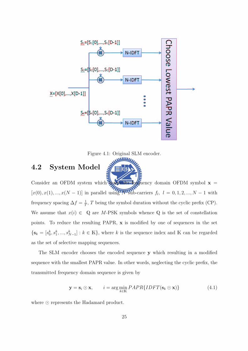
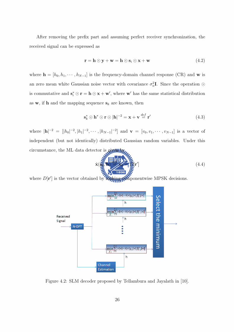
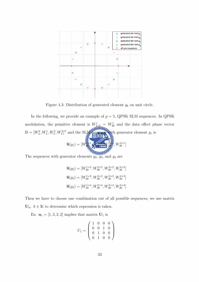
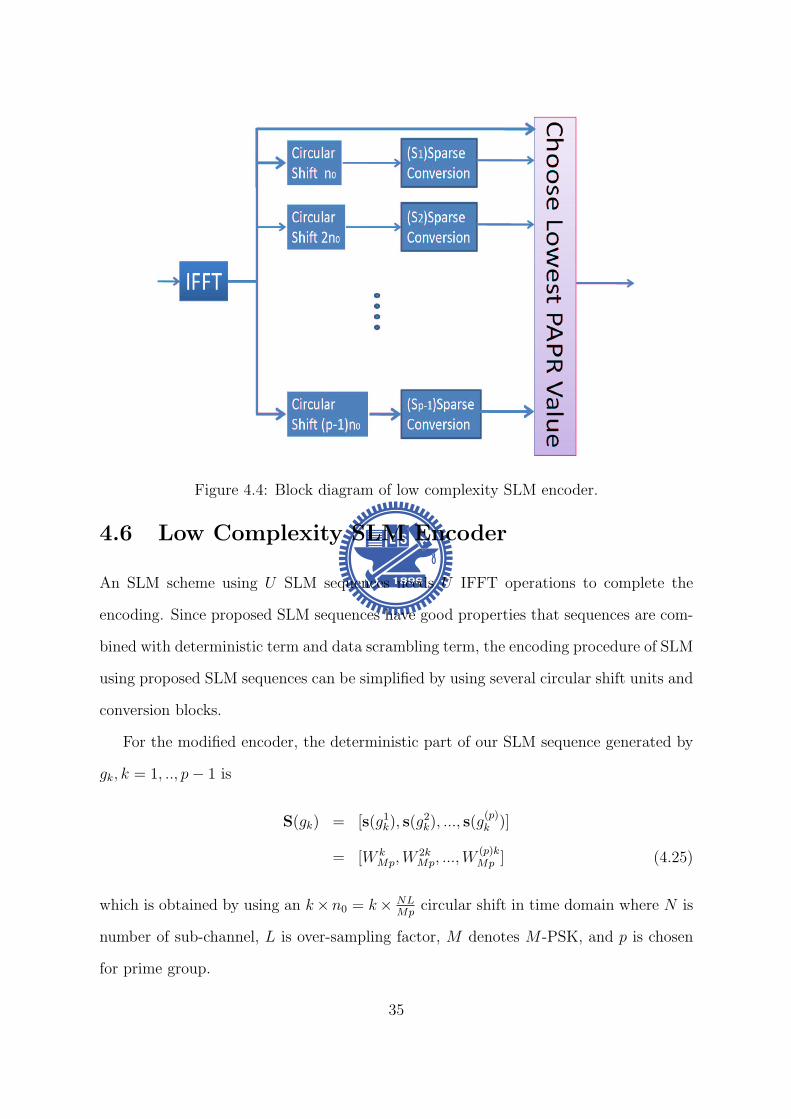
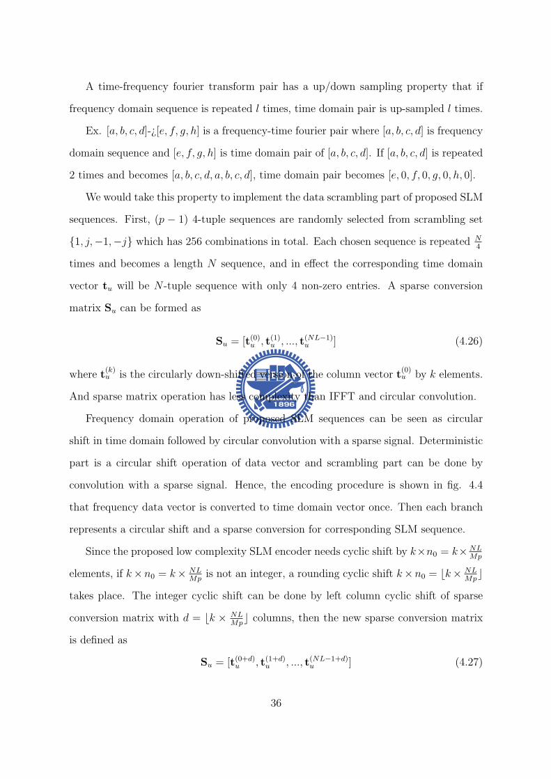
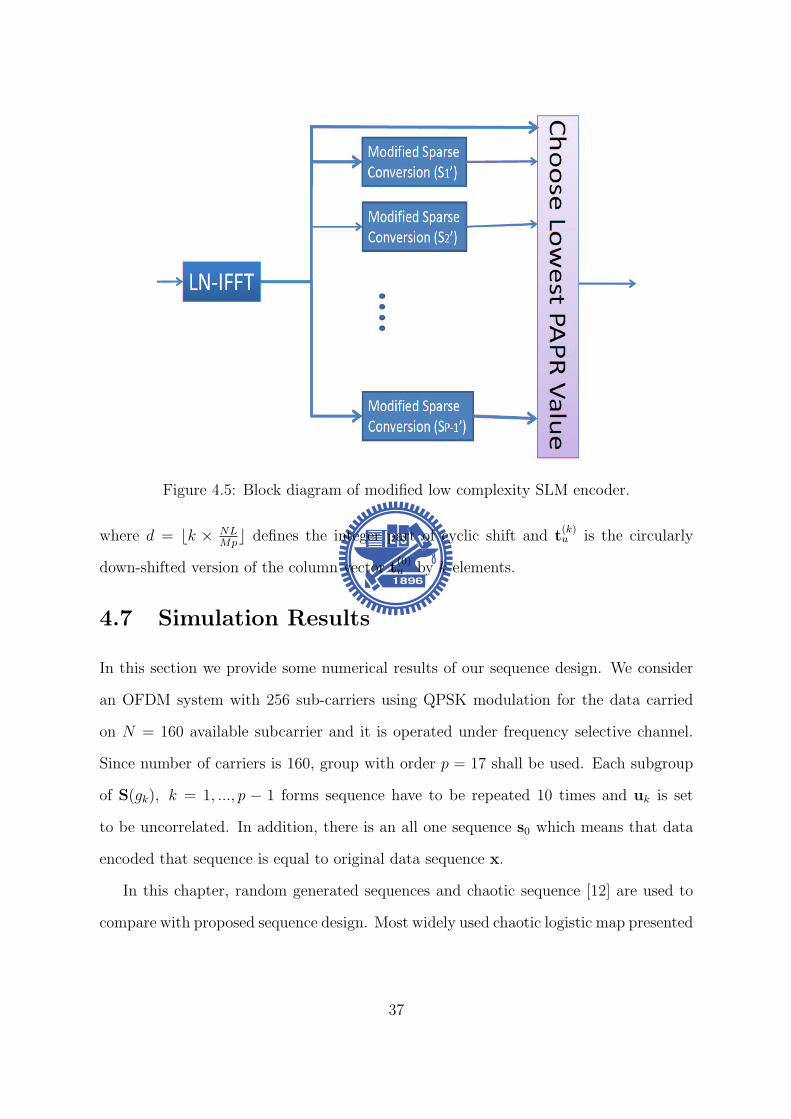
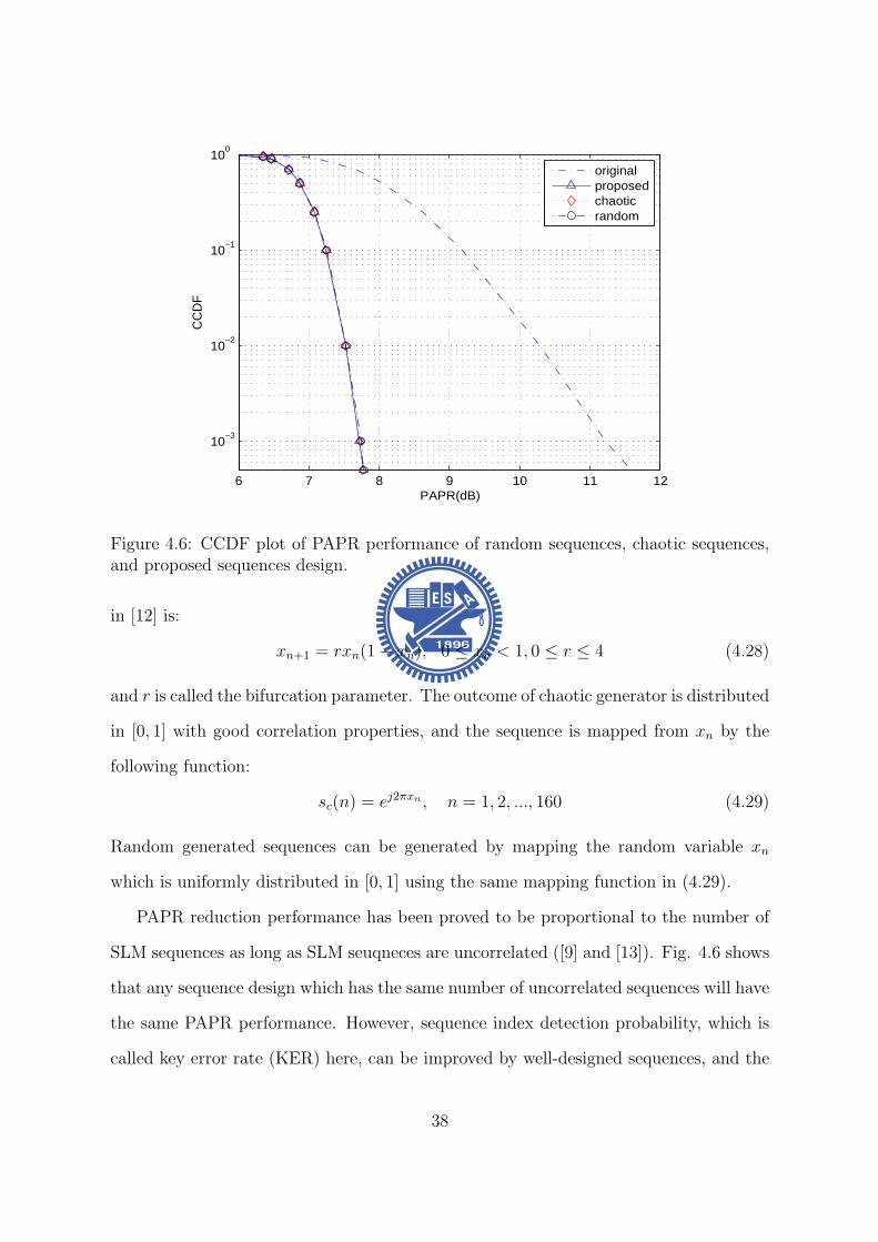
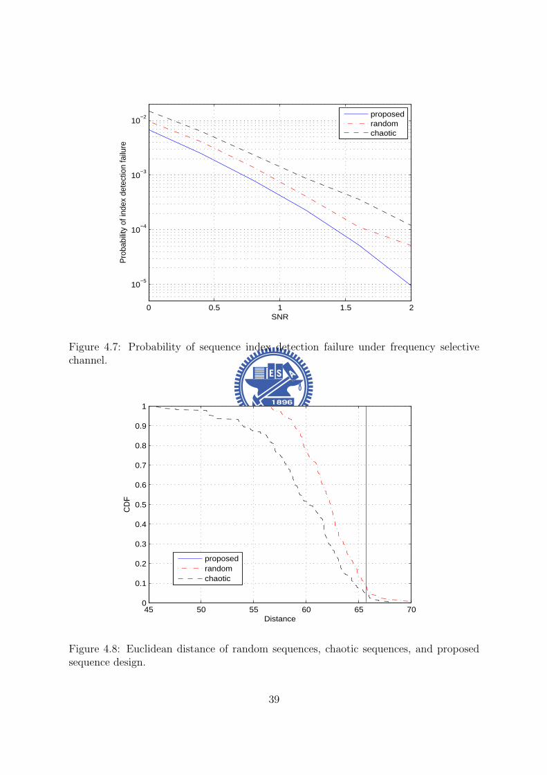
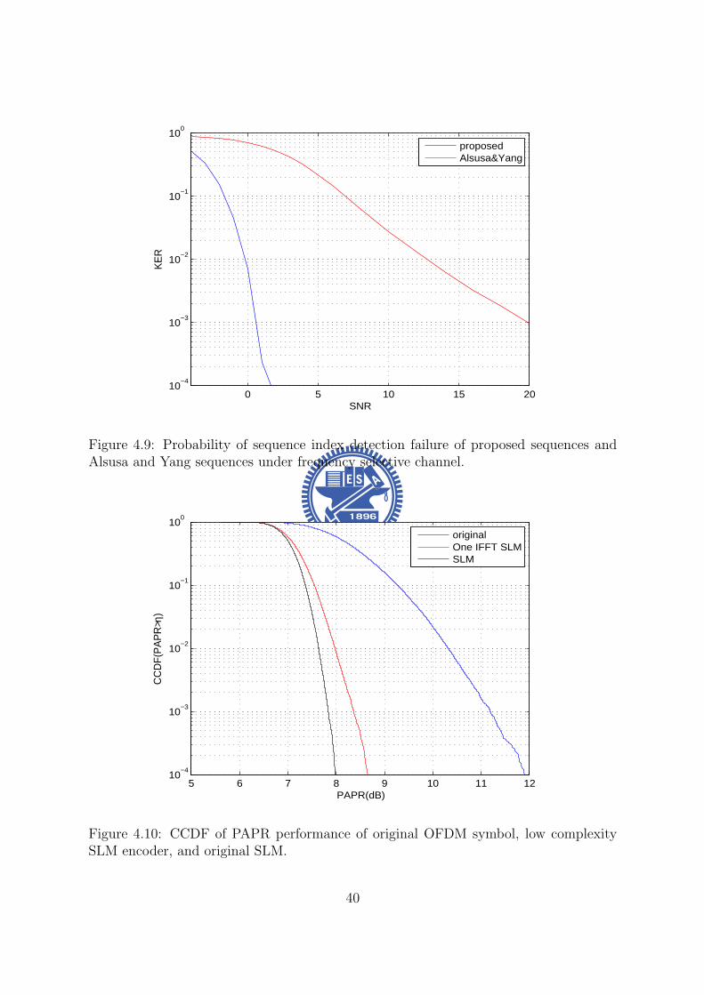
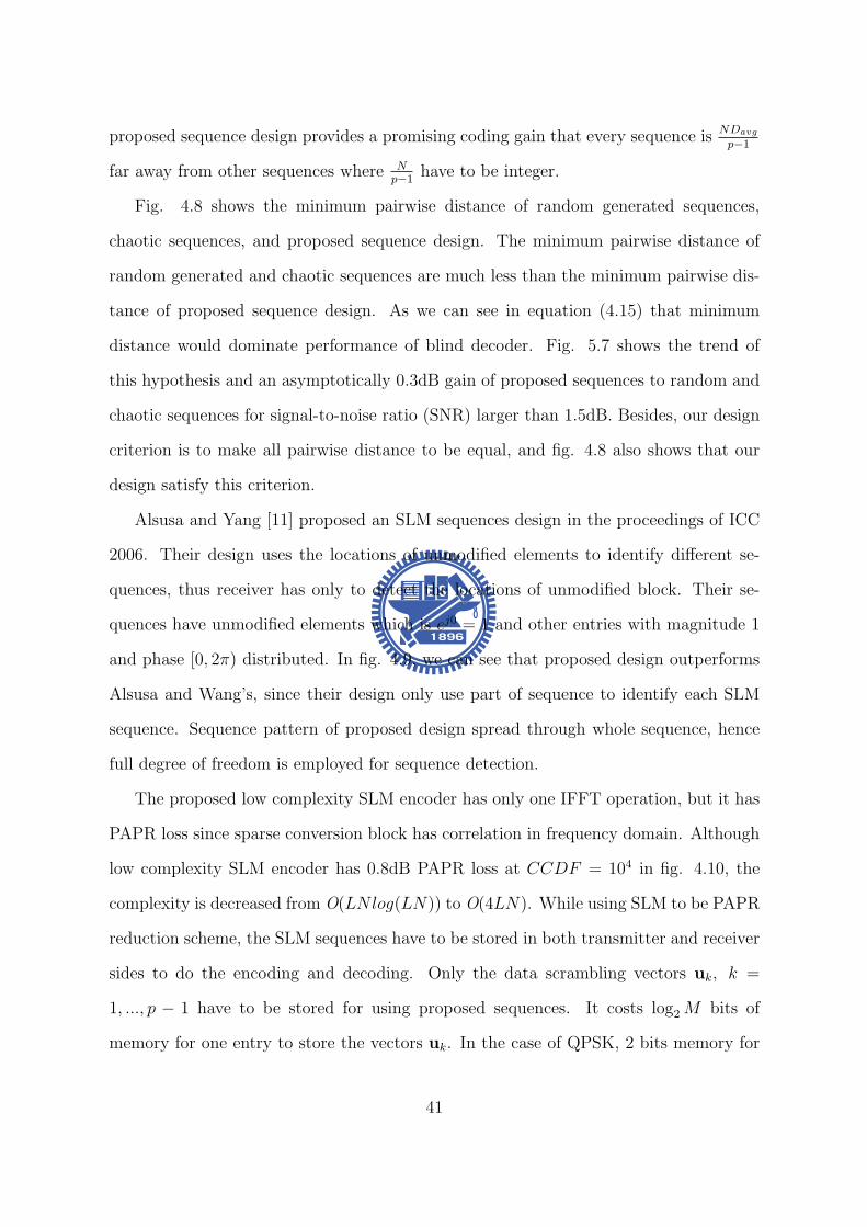
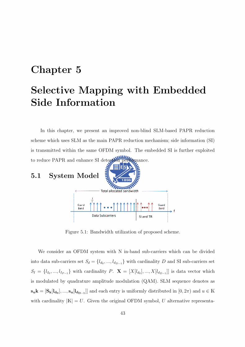
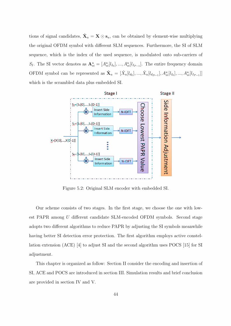
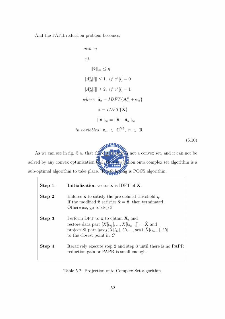
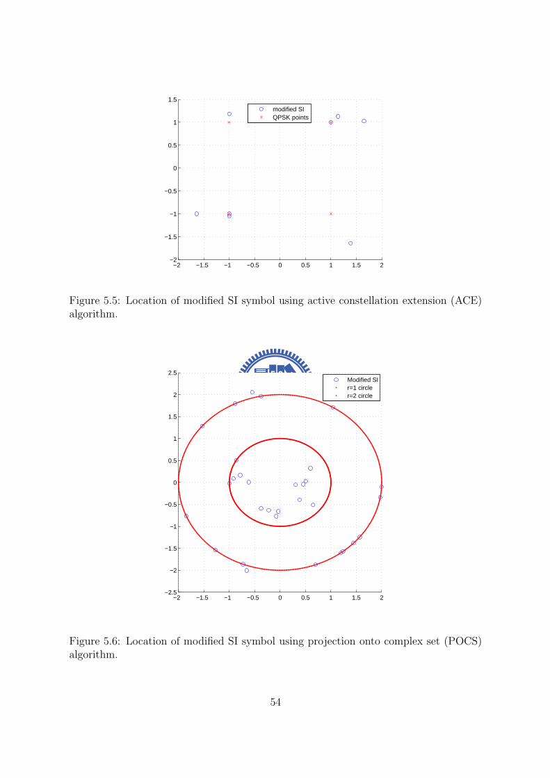
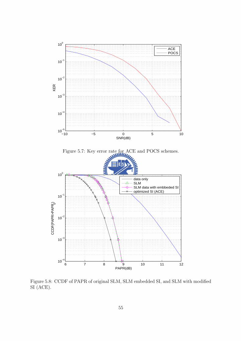
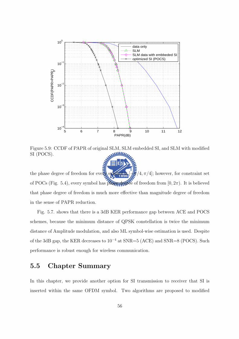
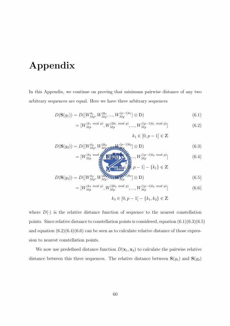