37757175 2 huawei bts3012 hardware structure
TRANSCRIPT
8/8/2019 37757175 2 HUAWEI BTS3012 Hardware Structure
http://slidepdf.com/reader/full/37757175-2-huawei-bts3012-hardware-structure 1/68
Page 1
Know the functions and features of BTS
Know the BTS hardware structure
8/8/2019 37757175 2 HUAWEI BTS3012 Hardware Structure
http://slidepdf.com/reader/full/37757175-2-huawei-bts3012-hardware-structure 2/68
8/8/2019 37757175 2 HUAWEI BTS3012 Hardware Structure
http://slidepdf.com/reader/full/37757175-2-huawei-bts3012-hardware-structure 3/68
Page 3
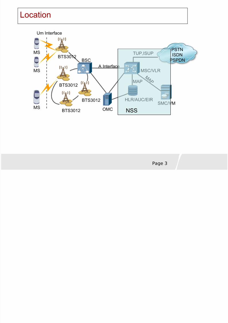
Location
PSTNISDN
PSPDN
Um Interface
BTS3012
BTS3012
BTS3012
BTS3012
OMC
HLR/AUC/EIR
BSC
MSC/VLR
SMC/VM
A Interface
MAP M A P
TUP,ISUPMS
MS
MS
NSS
8/8/2019 37757175 2 HUAWEI BTS3012 Hardware Structure
http://slidepdf.com/reader/full/37757175-2-huawei-bts3012-hardware-structure 4/68
Page 4
Functions (BTS)
BTS is the radio part of the BSSIt implements the radio transmission and radio channelcontrol for its subscribers (MSs) through the air interface
It also provides the wired interface functions to BSC.BTS is the radio transceiver controlled by the BSC to serve acertain cell
8/8/2019 37757175 2 HUAWEI BTS3012 Hardware Structure
http://slidepdf.com/reader/full/37757175-2-huawei-bts3012-hardware-structure 5/68
Page 5
BTS consists of
RFS (Radio Frequency Subsystem)
Common subsystem
8/8/2019 37757175 2 HUAWEI BTS3012 Hardware Structure
http://slidepdf.com/reader/full/37757175-2-huawei-bts3012-hardware-structure 6/68
Page 6
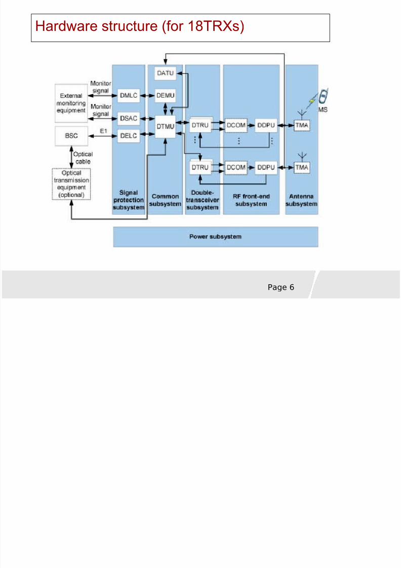
Hardware structure (for 18TRXs)
8/8/2019 37757175 2 HUAWEI BTS3012 Hardware Structure
http://slidepdf.com/reader/full/37757175-2-huawei-bts3012-hardware-structure 7/68Page 7
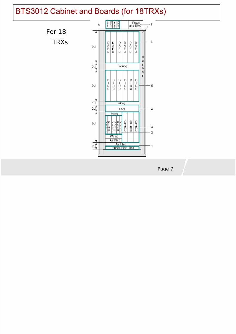
BTS3012 Cabinet and Boards (for 18TRXs)
For 18
TRXs
8/8/2019 37757175 2 HUAWEI BTS3012 Hardware Structure
http://slidepdf.com/reader/full/37757175-2-huawei-bts3012-hardware-structure 8/68Page 8
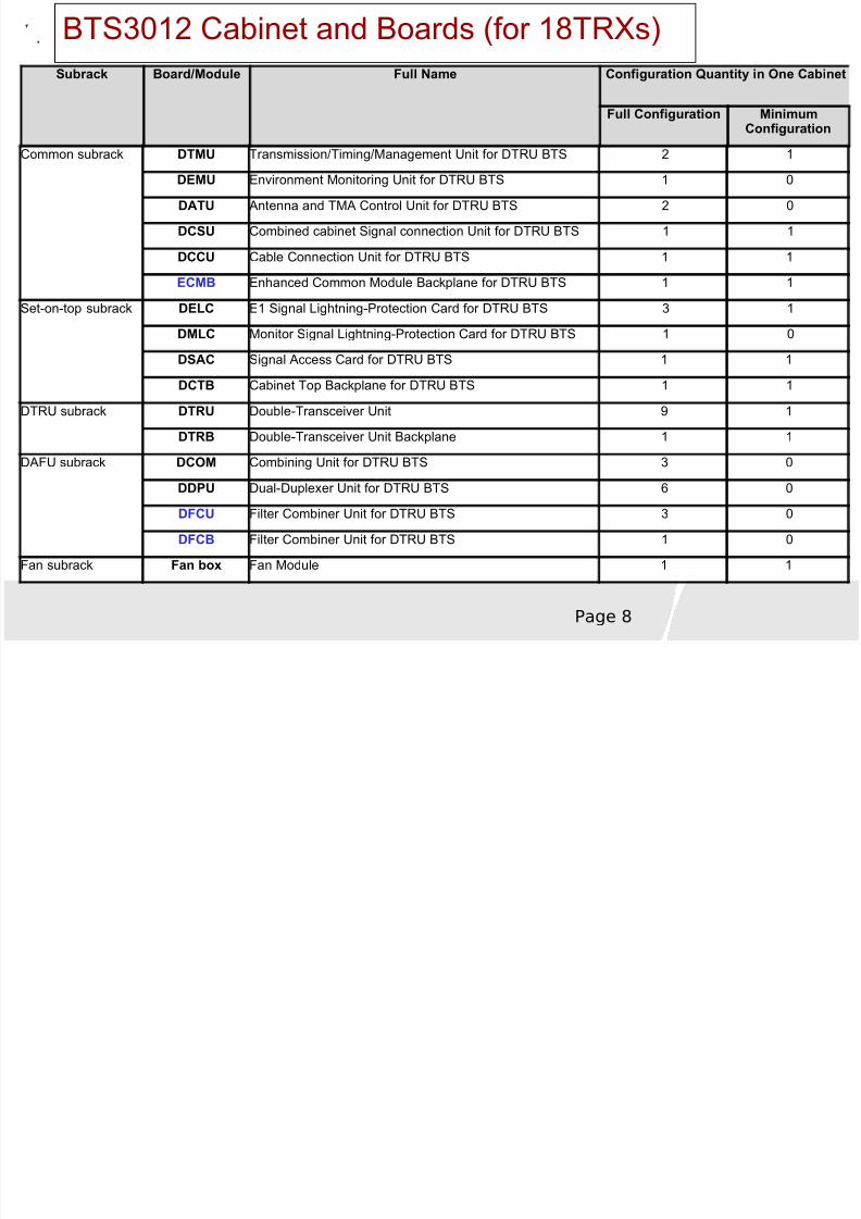
BTS3012 Cabinet and Boards (for 18TRXs)Subrack Board/Module Full Name Configuration Quantity in One Cabinet
Full Configuration MinimumConfiguration
Common subrack DTMU Transmission/Timing/Management Unit for DTRU BTS 2 1
DEMU Environment Monitoring Unit for DTRU BTS 1 0
DATU Antenna and TMA Control Unit for DTRU BTS 2 0
DCSU Combined cabinet Signal connection Unit for DTRU BTS 1 1
DCCU Cable Connection Unit for DTRU BTS 1 1
ECMB Enhanced Common Module Backplane for DTRU BTS 1 1
Set-on-top subrack DELC E1 Signal Lightning-Protection Card for DTRU BTS 3 1
DMLC Monitor Signal Lightning-Protection Card for DTRU BTS 1 0
DSAC Signal Access Card for DTRU BTS 1 1
DCTB Cabinet Top Backplane for DTRU BTS 1 1
DTRU subrack DTRU Double-Transceiver Unit 9 1
DTRB Double-Transceiver Unit Backplane 1 1
DAFU subrack DCOM Combining Unit for DTRU BTS 3 0
DDPU Dual-Duplexer Unit for DTRU BTS 6 0
DFCU Filter Combiner Unit for DTRU BTS 3 0
DFCB Filter Combiner Unit for DTRU BTS 1 0
Fan subrack Fan box Fan Module 1 1
8/8/2019 37757175 2 HUAWEI BTS3012 Hardware Structure
http://slidepdf.com/reader/full/37757175-2-huawei-bts3012-hardware-structure 9/68Page 9
Common Subsystem
DTMU Transmission/Timing/Management Unit for DTRU BTS
DEMU Environment Monitoring Unit for DTRU BTS
DCSU Combined cabinet Signal connection Unit for DTRU BTS
DCCU Cable Connection Unit for DTRU BTSDATU Antenna and TMA control Unit for DTRU BTS
8/8/2019 37757175 2 HUAWEI BTS3012 Hardware Structure
http://slidepdf.com/reader/full/37757175-2-huawei-bts3012-hardware-structure 10/68
Page 10
Functions of DTMU
Controls, maintains, and operates the BTS
Downloads software for the BTSProvides fault management, configuration management,performance management, and security managementProvides centralized clock distribution and management of
the entire BTS, and the hot backup of the clock unitProvides backup for the E1 ports and the main control unitMonitors the external fan control board and the power modules
8/8/2019 37757175 2 HUAWEI BTS3012 Hardware Structure
http://slidepdf.com/reader/full/37757175-2-huawei-bts3012-hardware-structure 11/68
Page 11
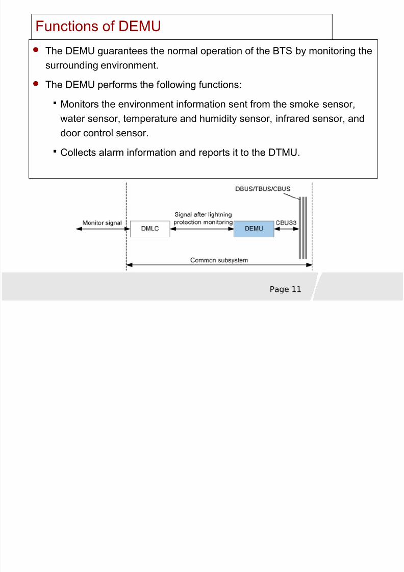
Functions of DEMU
The DEMU guarantees the normal operation of the BTS by monitoring thesurrounding environment.
The DEMU performs the following functions:
Monitors the environment information sent from the smoke sensor,water sensor, temperature and humidity sensor, infrared sensor, anddoor control sensor.
Collects alarm information and reports it to the DTMU.
8/8/2019 37757175 2 HUAWEI BTS3012 Hardware Structure
http://slidepdf.com/reader/full/37757175-2-huawei-bts3012-hardware-structure 12/68
Page 12
Functions of DCSU
The Combined cabinet Signal connection Unit for DTRU BTS (DCSU) isplaced in slot 5 of the common subrack. The DCSU is a mandatoryboard. Only one DCSU can be configured.
The DCSU performs the following functions:
Transmits clock signals, data signals, and control signals between themain cabinet and the extension cabinet.
Transmits the clock signals, data signals, and control signals from theDTMU to the DTRU ( for BTS3012 ) or QTRUs ( for 36TRXs).Ⅱ
8/8/2019 37757175 2 HUAWEI BTS3012 Hardware Structure
http://slidepdf.com/reader/full/37757175-2-huawei-bts3012-hardware-structure 13/68
Page 13
Double transceiver subsystem (BTS3012 ) Ⅱ
DTRU (Double Transceiver Unit)
DTRB
8/8/2019 37757175 2 HUAWEI BTS3012 Hardware Structure
http://slidepdf.com/reader/full/37757175-2-huawei-bts3012-hardware-structure 14/68
Page 14
Functions of DTRU (BTS3012 ) Ⅱ
Baseband Processing Part
Processes the signaling, such as coding, decoding, interleaving, de-interleaving, modulation, and demodulation.
Amplifies the output power.
RF Transmitting Part
Modulates the baseband signals into RF signals , and performs frequencyhopping.
Transmit RF signal to DDPU.
RF Receiving Part
Demodulates the RF signals into baseband signals, and performs
frequency hopping.
Divides the received RF signals and performs receive diversity.
8/8/2019 37757175 2 HUAWEI BTS3012 Hardware Structure
http://slidepdf.com/reader/full/37757175-2-huawei-bts3012-hardware-structure 15/68
Page 15
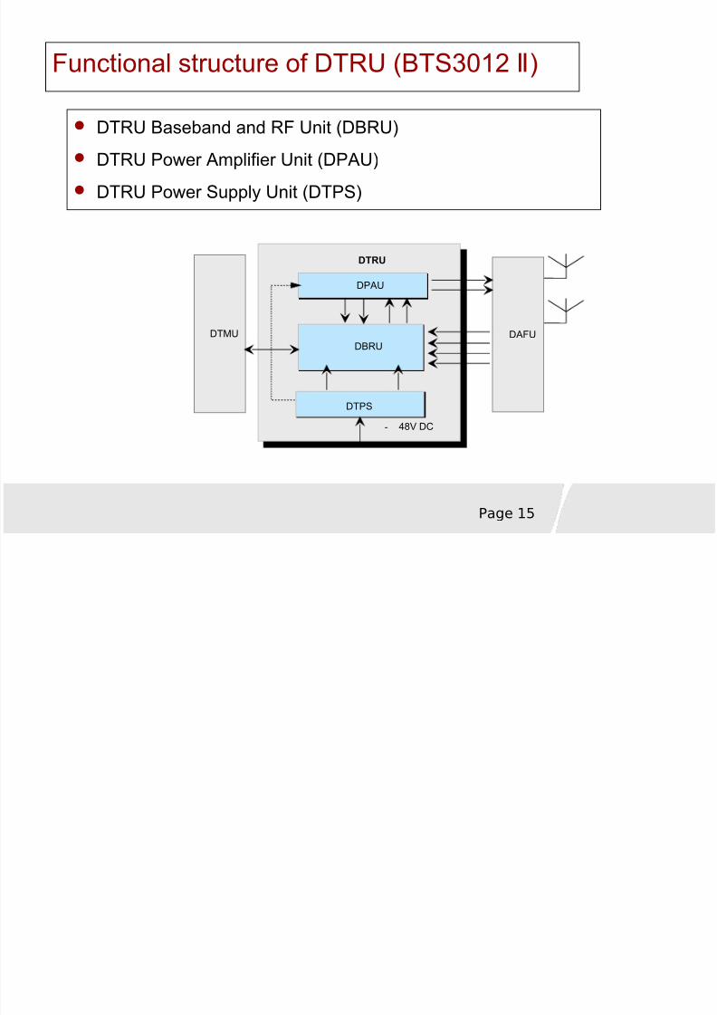
Functional structure of DTRU (BTS3012 ) Ⅱ
DTRU Baseband and RF Unit (DBRU)DTRU Power Amplifier Unit (DPAU)
DTRU Power Supply Unit (DTPS)
DTMU
DTPS
DTRU
- 48V DC
DPAU
DBRUDAFU
8/8/2019 37757175 2 HUAWEI BTS3012 Hardware Structure
http://slidepdf.com/reader/full/37757175-2-huawei-bts3012-hardware-structure 16/68
Page 16
RF Front-End Subsystem (BTS3012 ) Ⅱ
The functions of the BTS3012 RF front-end subsystem areⅡ
performed by the boards in the DAFU subrack.
The DAFU subrack can be configured with the DDPU, DCOM,DFCU, DFCB, or the combination of these modules.
DDPU (Dual Duplexer Unit for DTRU BTS)
DCOM (Combining Unit for DTRU BTS)
DFCU (Filter Combiner Unit for DTRU BTS)
DFCB (Filter Combiner Unit for DTRU BTS)
8/8/2019 37757175 2 HUAWEI BTS3012 Hardware Structure
http://slidepdf.com/reader/full/37757175-2-huawei-bts3012-hardware-structure 17/68
Page 17
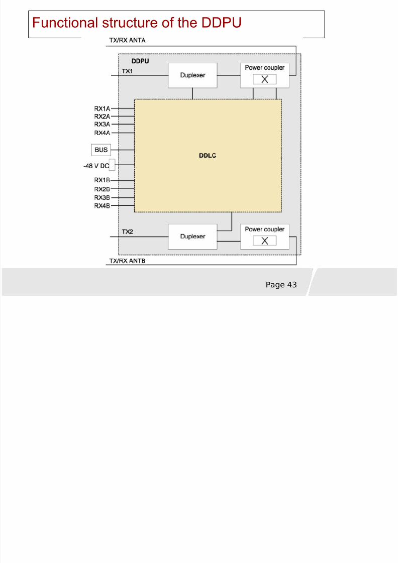
Functions of DDPU (BTS3012 ) Ⅱ
The DDPU performs the following functions:
Provides lightning protection through the ANT port.
Detects VSWR alarms in the antenna system.
Receives the gain control signals for the low noise amplifier.
Transmits multiple routes of RF signals from the transmitter tothe antenna.
Receives signals from the antenna, amplifies and quartersthese signals, and then transmits them to the receiver of theDTRU.

8/8/2019 37757175 2 HUAWEI BTS3012 Hardware Structure
http://slidepdf.com/reader/full/37757175-2-huawei-bts3012-hardware-structure 18/68
Page 18
Thank you
8/8/2019 37757175 2 HUAWEI BTS3012 Hardware Structure
http://slidepdf.com/reader/full/37757175-2-huawei-bts3012-hardware-structure 19/68
Page 19
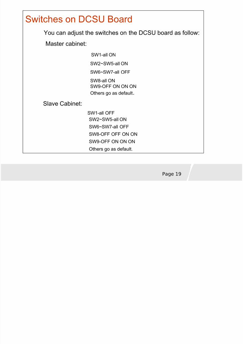
Switches on DCSU Board You can adjust the switches on the DCSU board as follow:
Master cabinet: SW1-all ON
SW2~SW5-all ON
SW6~SW7-all OFF
SW8-all ONSW9-OFF ON ON ONOthers go as default .
Slave Cabinet: SW1-all OFFSW2~SW5-all ON
SW6~SW7-all OFFSW8-OFF OFF ON ON
SW9-OFF ON ON ON
Others go as default.
8/8/2019 37757175 2 HUAWEI BTS3012 Hardware Structure
http://slidepdf.com/reader/full/37757175-2-huawei-bts3012-hardware-structure 20/68
Page 20
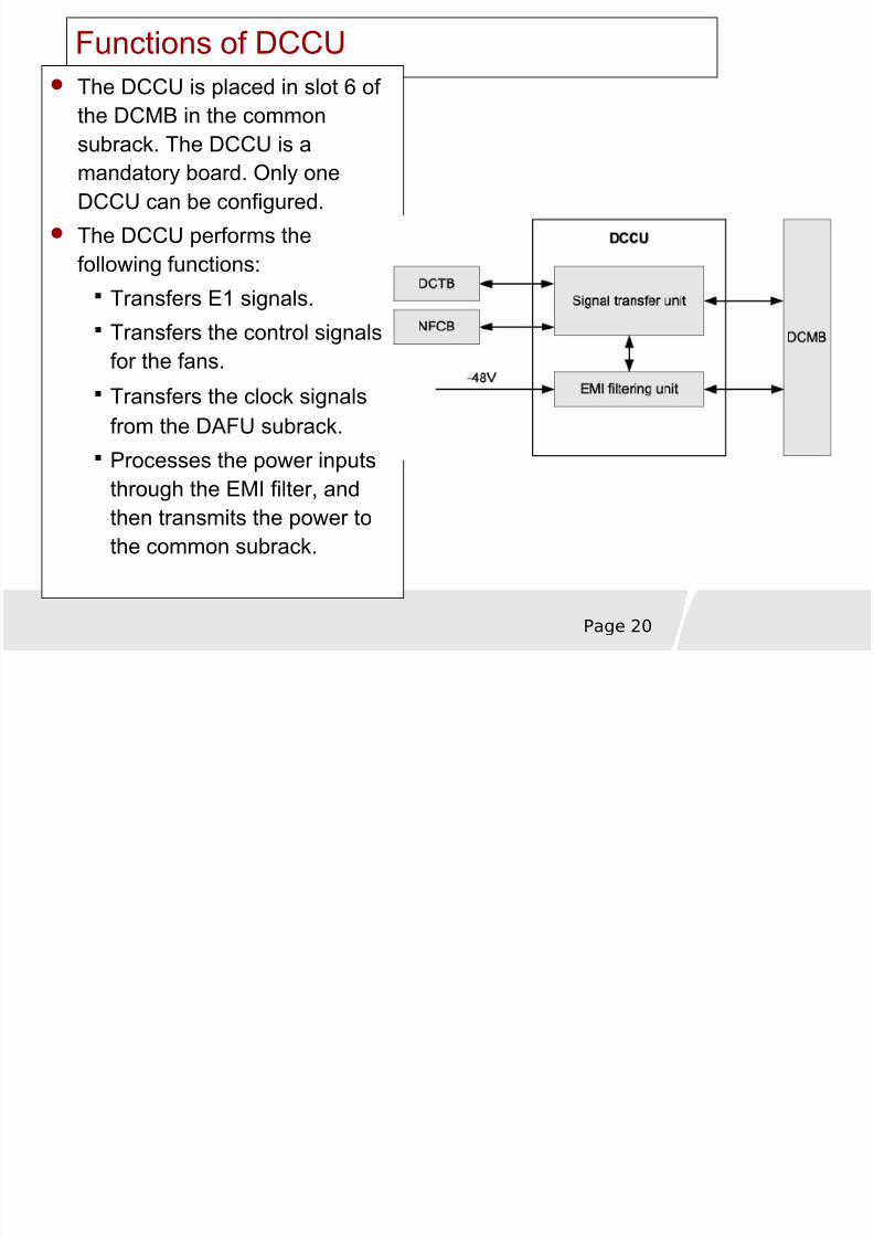
Functions of DCCUThe DCCU is placed in slot 6 of the DCMB in the common
subrack. The DCCU is amandatory board. Only oneDCCU can be configured.
The DCCU performs thefollowing functions:
Transfers E1 signals.Transfers the control signalsfor the fans.
Transfers the clock signalsfrom the DAFU subrack.
Processes the power inputsthrough the EMI filter, andthen transmits the power tothe common subrack.
8/8/2019 37757175 2 HUAWEI BTS3012 Hardware Structure
http://slidepdf.com/reader/full/37757175-2-huawei-bts3012-hardware-structure 21/68
Page 21
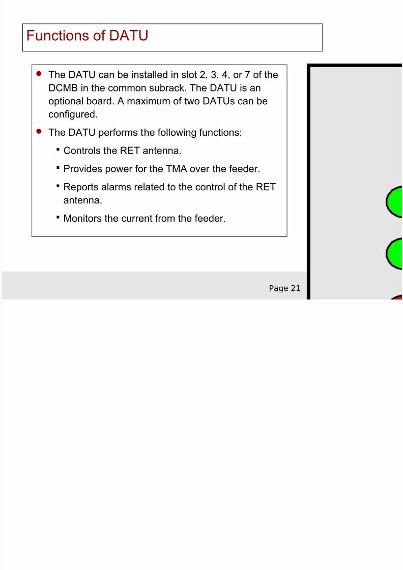
Functions of DATU
The DATU can be installed in slot 2, 3, 4, or 7 of theDCMB in the common subrack. The DATU is anoptional board. A maximum of two DATUs can beconfigured.
The DATU performs the following functions:
Controls the RET antenna.
Provides power for the TMA over the feeder.
Reports alarms related to the control of the RETantenna.
Monitors the current from the feeder.
8/8/2019 37757175 2 HUAWEI BTS3012 Hardware Structure
http://slidepdf.com/reader/full/37757175-2-huawei-bts3012-hardware-structure 22/68
8/8/2019 37757175 2 HUAWEI BTS3012 Hardware Structure
http://slidepdf.com/reader/full/37757175-2-huawei-bts3012-hardware-structure 23/68
Page 23
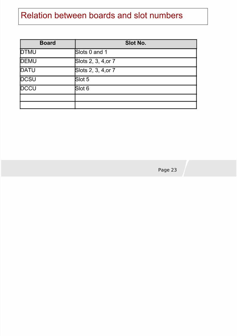
Relation between boards and slot numbers
Board Slot No.DTMU Slots 0 and 1
DEMU Slots 2, 3, 4,or 7
DATU Slots 2, 3, 4,or 7
DCSU Slot 5
DCCU Slot 6
8/8/2019 37757175 2 HUAWEI BTS3012 Hardware Structure
http://slidepdf.com/reader/full/37757175-2-huawei-bts3012-hardware-structure 24/68
Page 24
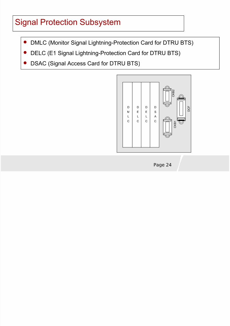
Signal Protection Subsystem
DMLC (Monitor Signal Lightning-Protection Card for DTRU BTS)
DELC (E1 Signal Lightning-Protection Card for DTRU BTS)
DSAC (Signal Access Card for DTRU BTS)
D
M
L
C
D
E
L
C
D
E
L
C
D
S
A
C
D C F
C K B 2
C K B 1
8/8/2019 37757175 2 HUAWEI BTS3012 Hardware Structure
http://slidepdf.com/reader/full/37757175-2-huawei-bts3012-hardware-structure 25/68
Page 25
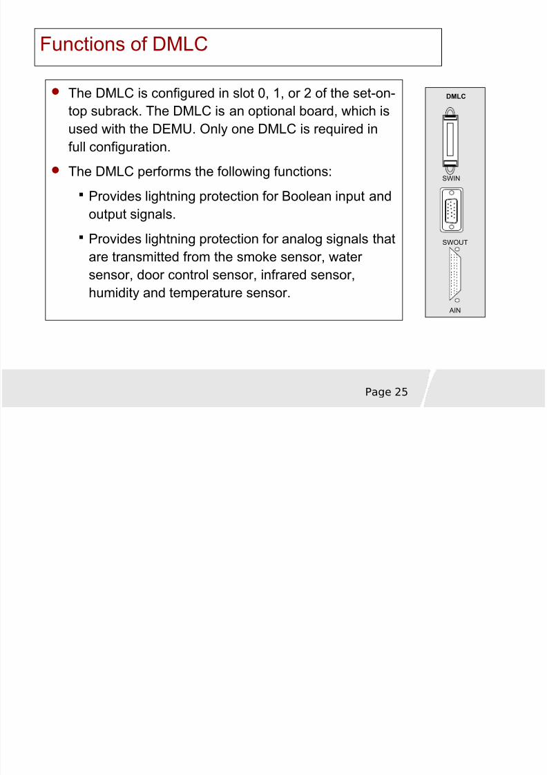
Functions of DMLC
The DMLC is configured in slot 0, 1, or 2 of the set-on-top subrack. The DMLC is an optional board, which isused with the DEMU. Only one DMLC is required infull configuration.
The DMLC performs the following functions:
Provides lightning protection for Boolean input andoutput signals.
Provides lightning protection for analog signals thatare transmitted from the smoke sensor, water sensor, door control sensor, infrared sensor,humidity and temperature sensor.
SWIN
SWOUT
DMLC
AIN
8/8/2019 37757175 2 HUAWEI BTS3012 Hardware Structure
http://slidepdf.com/reader/full/37757175-2-huawei-bts3012-hardware-structure 26/68
Page 26
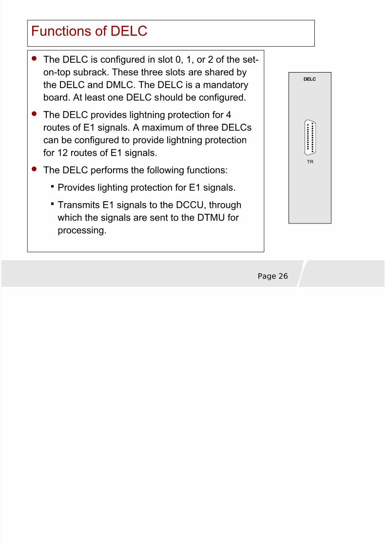
Functions of DELC
The DELC is configured in slot 0, 1, or 2 of the set-on-top subrack. These three slots are shared bythe DELC and DMLC. The DELC is a mandatoryboard. At least one DELC should be configured.
The DELC provides lightning protection for 4routes of E1 signals. A maximum of three DELCscan be configured to provide lightning protectionfor 12 routes of E1 signals.
The DELC performs the following functions:
Provides lighting protection for E1 signals.
Transmits E1 signals to the DCCU, throughwhich the signals are sent to the DTMU for processing.
DELC
TR
8/8/2019 37757175 2 HUAWEI BTS3012 Hardware Structure
http://slidepdf.com/reader/full/37757175-2-huawei-bts3012-hardware-structure 27/68
Page 27
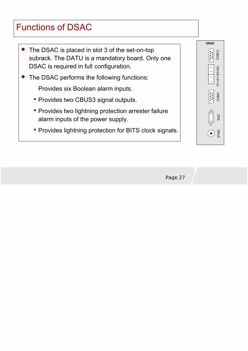
Functions of DSAC
The DSAC is placed in slot 3 of the set-on-topsubrack. The DATU is a mandatory board. Only oneDSAC is required in full configuration.
The DSAC performs the following functions:
Provides six Boolean alarm inputs.
Provides two CBUS3 signal outputs.
Provides two lightning protection arrester failurealarm inputs of the power supply.
Provides lightning protection for BITS clock signals.
DSAC
C O M 1
E A C
S Y N C
C O M
2
S 1 + S 1 - S
2 + S 2 -
8/8/2019 37757175 2 HUAWEI BTS3012 Hardware Structure
http://slidepdf.com/reader/full/37757175-2-huawei-bts3012-hardware-structure 28/68
Page 28
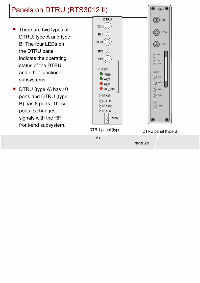
Panels on DTRU (BTS3012 ) Ⅱ
There are two types of
DTRU: type A and typeB. The four LEDs onthe DTRU panelindicate the operatingstatus of the DTRUand other functionalsubsystems.
DTRU (type A) has 10ports and DTRU (type
B) has 8 ports. Theseports exchangessignals with the RFfront-end subsystem.
DTRU panel (type
A) DTRU panel (type B)
8/8/2019 37757175 2 HUAWEI BTS3012 Hardware Structure
http://slidepdf.com/reader/full/37757175-2-huawei-bts3012-hardware-structure 29/68
Page 29
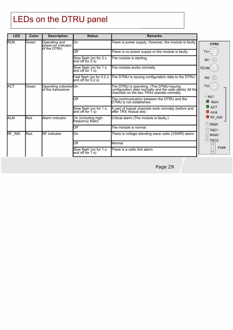
LEDs on the DTRU panel
LED Color Description Status Remarks
RUN Green Operating andpower-on indicator of the DTRU
On There is power supply. However, the module is faulty.
Off There is no power supply or the module is faulty.
Slow flash (on for 2 sand off for 2 s)
The module is starting.
Slow flash (on for 1 sand off for 1 s)
The module works normally.
Fast flash (on for 0.2 sand off for 0.2 s)
The DTMU is issuing configuration data to the DTRU.
ACT Green Operating indicator of the transceiver
On The DTRU is operating. (The DTMU issuingconfiguration data normally and the cells starts) All thechannels on the two TRXs operate normally.
Off The communication between the DTRU and theDTMU is not established.
Slow flash (on for 1 sand off for 1 s)
A part of logical channels work normally (before andafter TRX mutual aid).
ALM Red Alarm indicator On (including high-frequency flash)
Critical alarm (The module is faulty.)
Off The module is normal.
RF_IND Red RF indicator On There is voltage standing wave radio (VSWR) alarm.
Off Normal
Slow flash (on for 1 sand off for 1 s)
There is a radio link alarm.
8/8/2019 37757175 2 HUAWEI BTS3012 Hardware Structure
http://slidepdf.com/reader/full/37757175-2-huawei-bts3012-hardware-structure 30/68
Page 30
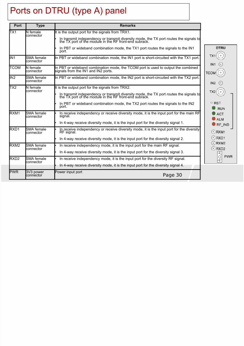
Ports on DTRU (type A) panelPort Type Remarks
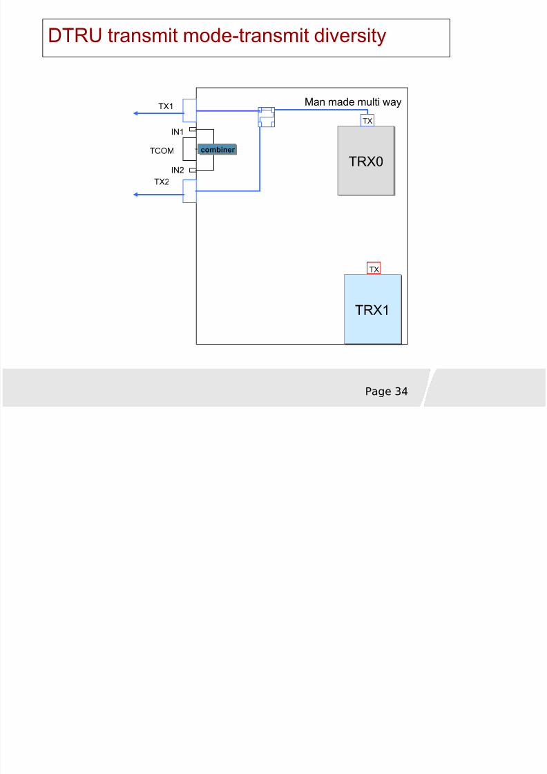
TX1 N femaleconnector
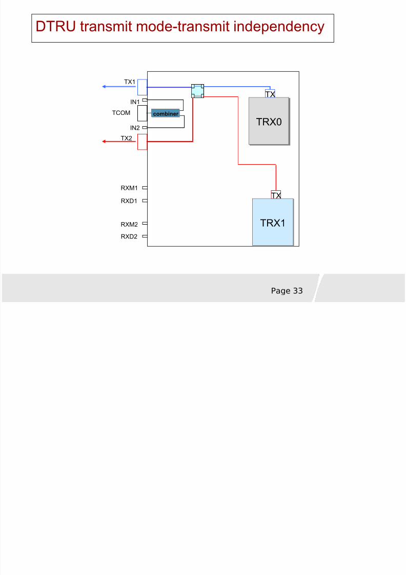
It is the output port for the signals from TRX1.
• In transmit independency or transmit diversity mode, the TX port routes the signals tothe TX port of the module in the RF front-end subrack.
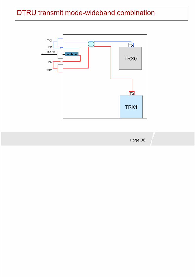
• In PBT or wideband combination mode, the TX1 port routes the signals to the IN1port.
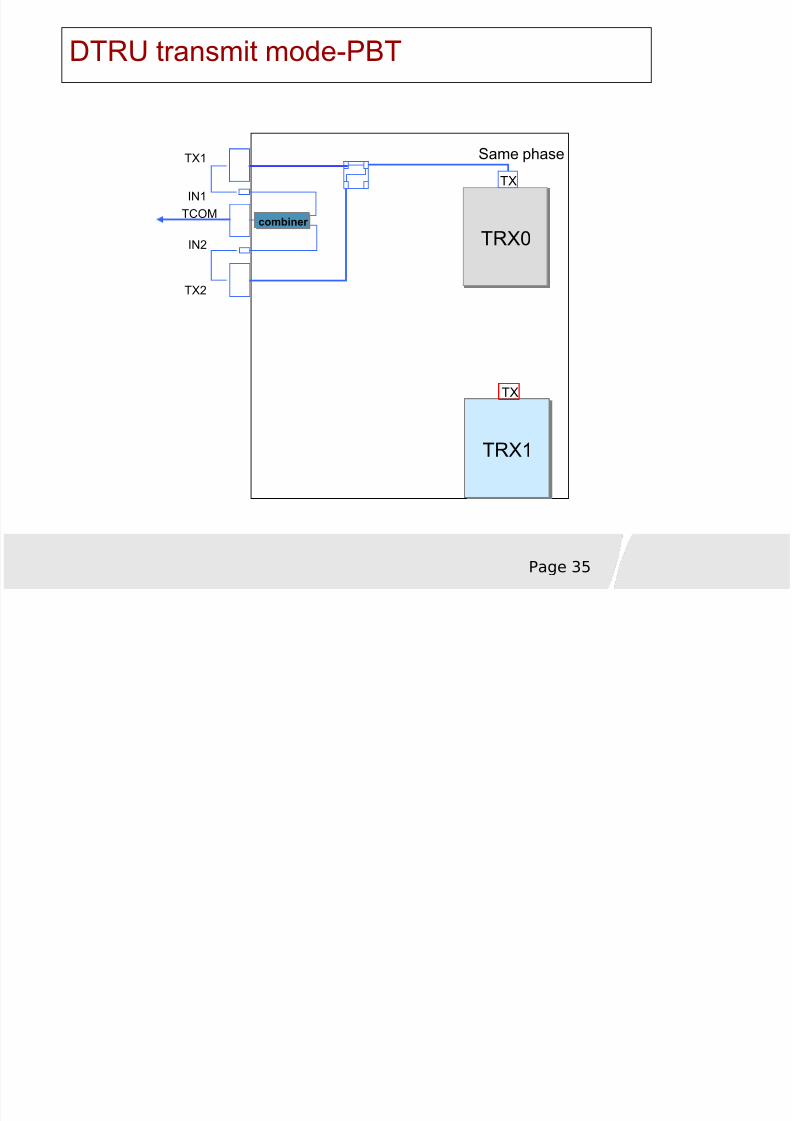
IN1 SMA femaleconnector
In PBT or wideband combination mode, the IN1 port is short-circuited with the TX1 port.
TCOM N femaleconnector
In PBT or wideband combination mode, the TCOM port is used to output the combinedsignals from the IN1 and IN2 ports.
IN2 SMA femaleconnector
In PBT or wideband combination mode, the IN2 port is short-circuited with the TX2 port.
TX2 N femaleconnector
It is the output port for the signals from TRX2.
• In transmit independency or transmit diversity mode, the TX port routes the signals tothe TX port of the module in the RF front-end subrack.
• In PBT or wideband combination mode, the TX2 port routes the signals to the IN2port.
RXM1 SMA femaleconnector
• In receive independency or receive diversity mode, it is the input port for the main RFsignal.
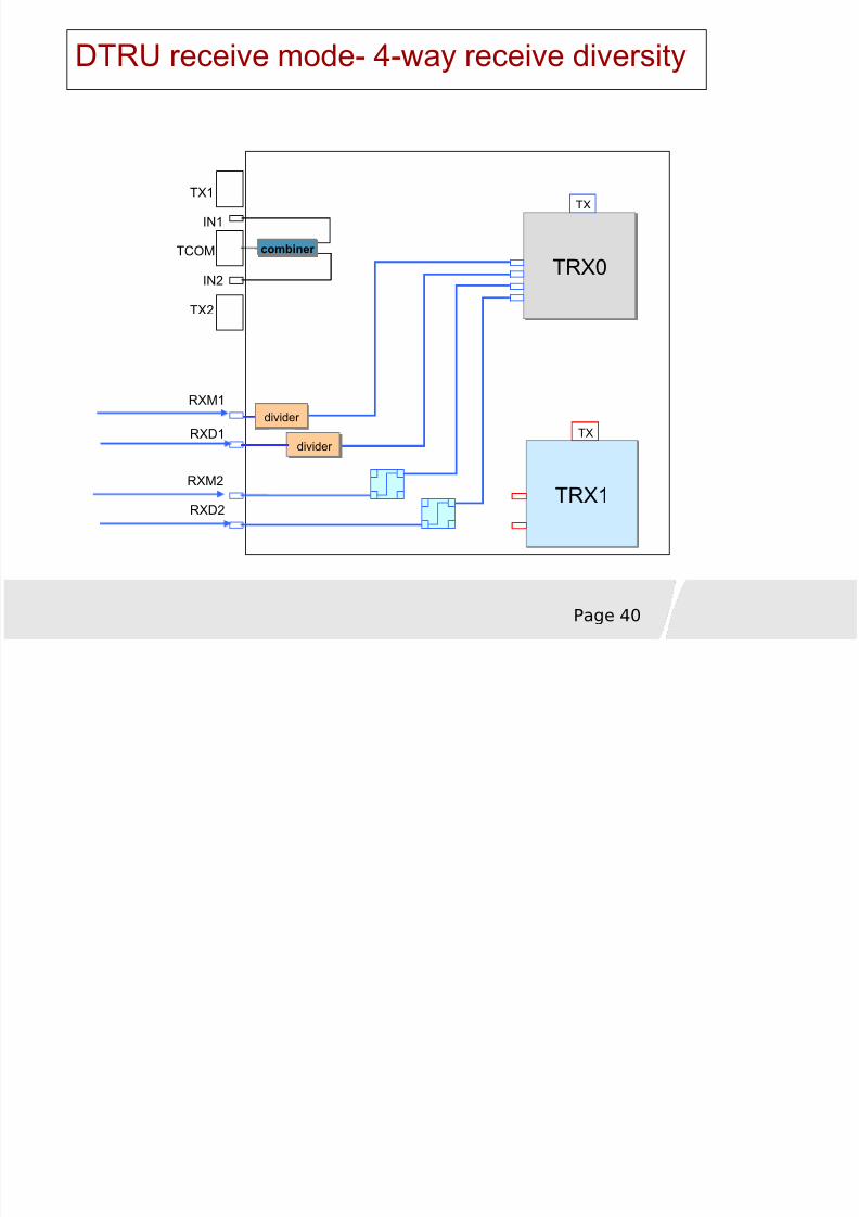
• In 4-way receive diversity mode, it is the input port for the diversity signal 1.
RXD1 SMA femaleconnector • In receive independency or receive diversity mode, it is the input port for the diversityRF signal.
• In 4-way receive diversity mode, it is the input port for the diversity signal 2.
RXM2 SMA femaleconnector
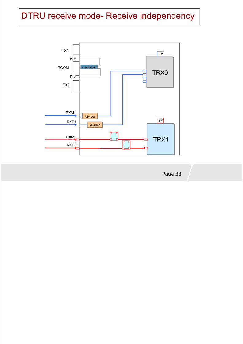
• In receive independency mode, it is the input port for the main RF signal.
• In 4-way receive diversity mode, it is the input port for the diversity signal 3.
RXD2 SMA femaleconnector
• In receive independency mode, it is the input port for the diversity RF signal.
• In 4-way receive diversity mode, it is the input port for the diversity signal 4.
PWR 3V3 power connector Power input port
8/8/2019 37757175 2 HUAWEI BTS3012 Hardware Structure
http://slidepdf.com/reader/full/37757175-2-huawei-bts3012-hardware-structure 31/68
Page 31
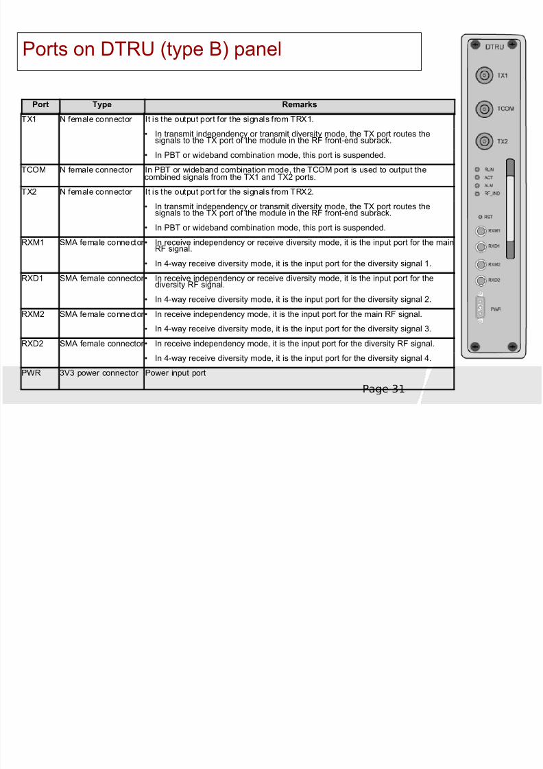
Ports on DTRU (type B) panel
Port Type Remarks
TX1 N female connector It is the output port for the signals from TRX1.
• In transmit independency or transmit diversity mode, the TX port routes thesignals to the TX port of the module in the RF front-end subrack.
• In PBT or wideband combination mode, this port is suspended.
TCOM N female connector In PBT or wideband combination mode, the TCOM port is used to output thecombined signals from the TX1 and TX2 ports.
TX2 N female connector It is the output port for the signals from TRX2.• In transmit independency or transmit diversity mode, the TX port routes the
signals to the TX port of the module in the RF front-end subrack.
• In PBT or wideband combination mode, this port is suspended.
RXM1 SMA female connector • In receive independency or receive diversity mode, it is the input port for the mainRF signal.
• In 4-way receive diversity mode, it is the input port for the diversity signal 1.
RXD1 SMA female connector • In receive independency or receive diversity mode, it is the input port for thediversity RF signal.
• In 4-way receive diversity mode, it is the input port for the diversity signal 2.
RXM2 SMA female connector • In receive independency mode, it is the input port for the main RF signal.
• In 4-way receive diversity mode, it is the input port for the diversity signal 3.
RXD2 SMA female connector • In receive independency mode, it is the input port for the diversity RF signal.
• In 4-way receive diversity mode, it is the input port for the diversity signal 4.
PWR 3V3 power connector Power input port
8/8/2019 37757175 2 HUAWEI BTS3012 Hardware Structure
http://slidepdf.com/reader/full/37757175-2-huawei-bts3012-hardware-structure 32/68
8/8/2019 37757175 2 HUAWEI BTS3012 Hardware Structure
http://slidepdf.com/reader/full/37757175-2-huawei-bts3012-hardware-structure 33/68
Page 33
DTRU transmit mode-transmit independency
TCOM
TRX0TRX0
TX
TRX1TRX1
TX
TX1
IN1
IN2
TX2
RXM1
RXD1
RXM2
RXD2
combiner combiner
8/8/2019 37757175 2 HUAWEI BTS3012 Hardware Structure
http://slidepdf.com/reader/full/37757175-2-huawei-bts3012-hardware-structure 34/68
Page 34
DTRU transmit mode-transmit diversity
TRX1
TRX0TRX0
TX
TX
TX1
IN1
TCOM
IN2TX2
Man made multi way
combiner combiner
8/8/2019 37757175 2 HUAWEI BTS3012 Hardware Structure
http://slidepdf.com/reader/full/37757175-2-huawei-bts3012-hardware-structure 35/68
Page 35
DTRU transmit mode-PBT
TRX1TRX1
TRX0TRX0
TX
TX
TX1
IN1TCOM
IN2
TX2
Same phase
combiner combiner
8/8/2019 37757175 2 HUAWEI BTS3012 Hardware Structure
http://slidepdf.com/reader/full/37757175-2-huawei-bts3012-hardware-structure 36/68
Page 36
DTRU transmit mode-wideband combination
TRX0TRX0
TX
TRX1TRX1
TX
TX1
IN1
TCOM
IN2
TX2
combiner combiner
8/8/2019 37757175 2 HUAWEI BTS3012 Hardware Structure
http://slidepdf.com/reader/full/37757175-2-huawei-bts3012-hardware-structure 37/68
Page 37
DTRU receive modes
Receive independency
Receive diversity
4-way receive diversity
8/8/2019 37757175 2 HUAWEI BTS3012 Hardware Structure
http://slidepdf.com/reader/full/37757175-2-huawei-bts3012-hardware-structure 38/68
Page 38
DTRU receive mode- Receive independency
TRX1TRX1
TRX0TRX0
TX
TX
TX1
IN1
TCOM
IN2
TX2
RXM1
RXD1
RXM2
RXD2
divider divider
combiner combiner
divider divider

8/8/2019 37757175 2 HUAWEI BTS3012 Hardware Structure
http://slidepdf.com/reader/full/37757175-2-huawei-bts3012-hardware-structure 39/68
Page 39
DTRU receive mode- Receive diversity
TRX0TRX0
TX
TRX1TRX1
TX
TX1
IN1
TCOM
IN2
TX2
RXM1
RXD1
RXM2
RXD2
combiner combiner
divider divider
divider divider
8/8/2019 37757175 2 HUAWEI BTS3012 Hardware Structure
http://slidepdf.com/reader/full/37757175-2-huawei-bts3012-hardware-structure 40/68
8/8/2019 37757175 2 HUAWEI BTS3012 Hardware Structure
http://slidepdf.com/reader/full/37757175-2-huawei-bts3012-hardware-structure 41/68
Page 41
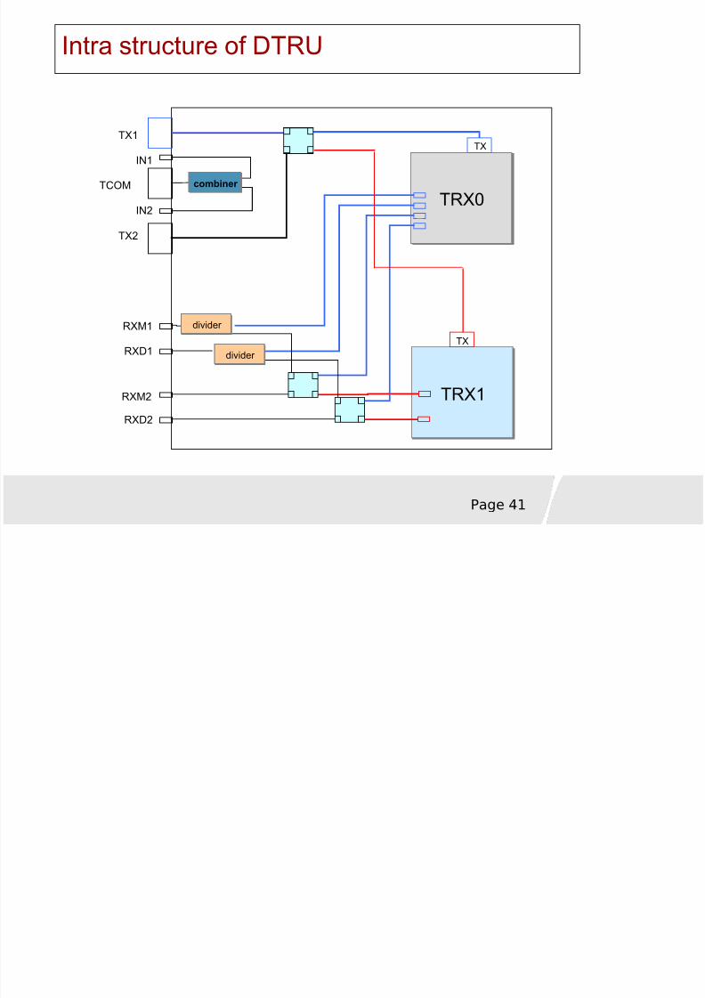
Intra structure of DTRU
TRX0TRX0
TX
TRX1TRX1
TX
TX1
IN1
TCOM
IN2
TX2
RXM1
RXD1
RXM2
RXD2
combiner combiner
divider divider
divider divider
8/8/2019 37757175 2 HUAWEI BTS3012 Hardware Structure
http://slidepdf.com/reader/full/37757175-2-huawei-bts3012-hardware-structure 42/68
Page 42
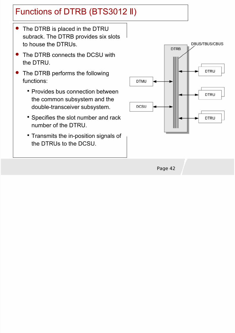
Functions of DTRB (BTS3012 ) Ⅱ
The DTRB is placed in the DTRUsubrack. The DTRB provides six slotsto house the DTRUs.
The DTRB connects the DCSU withthe DTRU.
The DTRB performs the following
functions:Provides bus connection betweenthe common subsystem and thedouble-transceiver subsystem.
Specifies the slot number and rack
number of the DTRU.Transmits the in-position signals of the DTRUs to the DCSU.
8/8/2019 37757175 2 HUAWEI BTS3012 Hardware Structure
http://slidepdf.com/reader/full/37757175-2-huawei-bts3012-hardware-structure 43/68
Page 43
Functional structure of the DDPU
8/8/2019 37757175 2 HUAWEI BTS3012 Hardware Structure
http://slidepdf.com/reader/full/37757175-2-huawei-bts3012-hardware-structure 44/68
Page 44
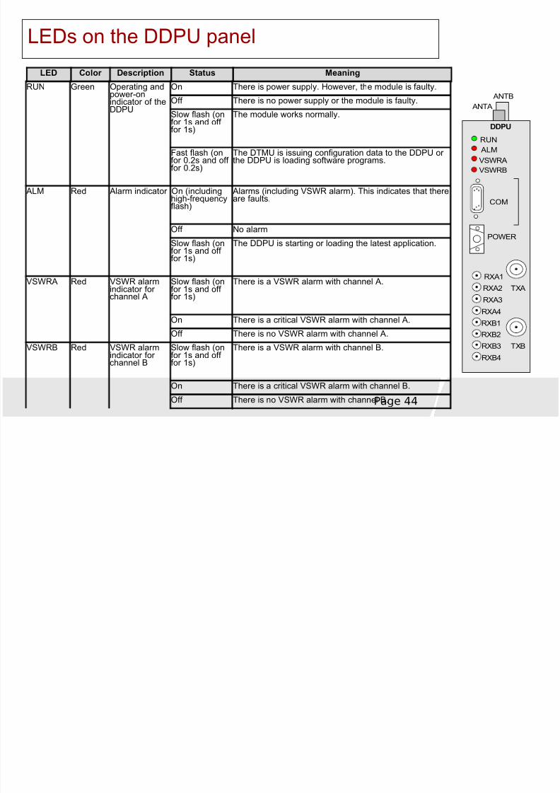
LEDs on the DDPU panel
RUN
ALM
VSWRA
RXA1
RXA2
RXA3
RXA4
RXB1
RXB2
RXB3
RXB4
DDPU
TXA
TXB
COM
POWER
VSWRB
ANTA
ANTB
LED Color Description Status Meaning
RUN Green Operating andpower-onindicator of theDDPU
On There is power supply. However, the module is faulty.
Off There is no power supply or the module is faulty.Slow flash (onfor 1s and off for 1s)
The module works normally.
Fast flash (onfor 0.2s and off for 0.2s)
The DTMU is issuing configuration data to the DDPU or the DDPU is loading software programs.
ALM Red Alarm indicator On (includinghigh-frequencyflash)
Alarms (including VSWR alarm). This indicates that thereare faults.
Off No alarm
Slow flash (onfor 1s and off for 1s)
The DDPU is starting or loading the latest application.
VSWRA Red VSWR alarmindicator for channel A
Slow flash (onfor 1s and off for 1s)
There is a VSWR alarm with channel A.
On There is a critical VSWR alarm with channel A.
Off There is no VSWR alarm with channel A.
VSWRB Red VSWR alarmindicator for channel B
Slow flash (onfor 1s and off for 1s)
There is a VSWR alarm with channel B.
On There is a critical VSWR alarm with channel B.
Off There is no VSWR alarm with channel B.
8/8/2019 37757175 2 HUAWEI BTS3012 Hardware Structure
http://slidepdf.com/reader/full/37757175-2-huawei-bts3012-hardware-structure 45/68
8/8/2019 37757175 2 HUAWEI BTS3012 Hardware Structure
http://slidepdf.com/reader/full/37757175-2-huawei-bts3012-hardware-structure 46/68
Page 46
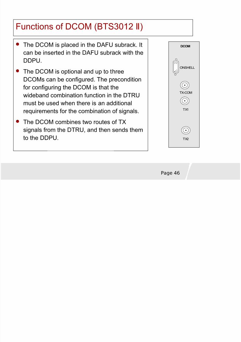
Functions of DCOM (BTS3012 ) Ⅱ
The DCOM is placed in the DAFU subrack. Itcan be inserted in the DAFU subrack with theDDPU.
The DCOM is optional and up to threeDCOMs can be configured. The precondition
for configuring the DCOM is that thewideband combination function in the DTRUmust be used when there is an additionalrequirements for the combination of signals.
The DCOM combines two routes of TXsignals from the DTRU, and then sends themto the DDPU.
DCOM
TX-COM
TX2
TX1
ONSHELL
8/8/2019 37757175 2 HUAWEI BTS3012 Hardware Structure
http://slidepdf.com/reader/full/37757175-2-huawei-bts3012-hardware-structure 47/68
Page 47
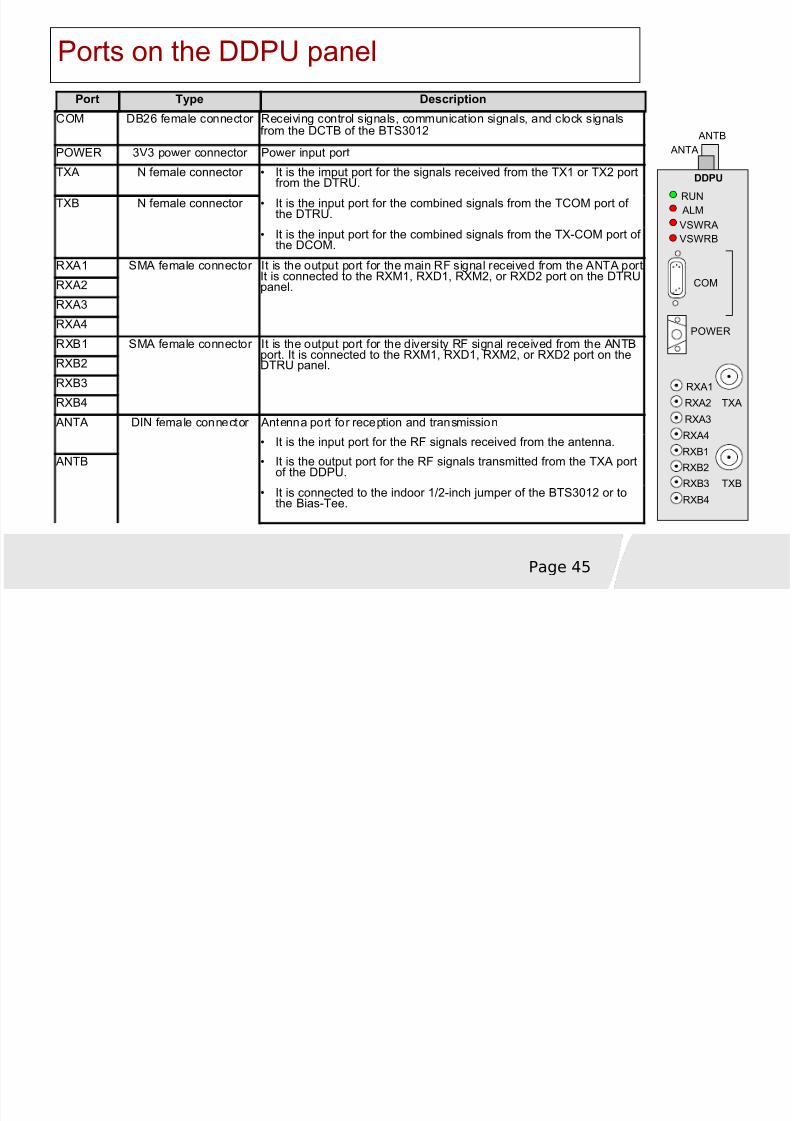
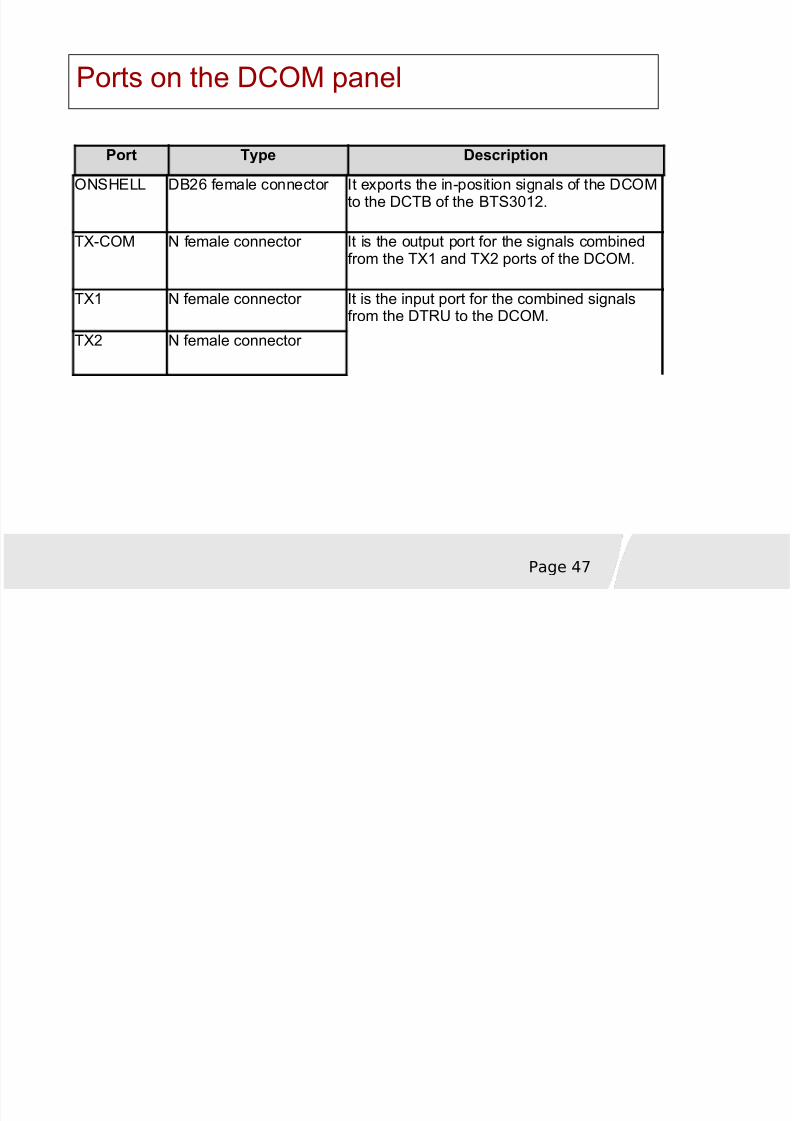
Ports on the DCOM panel
Port Type Description
ONSHELL DB26 female connector It exports the in-position signals of the DCOMto the DCTB of the BTS3012.
TX-COM N female connector It is the output port for the signals combinedfrom the TX1 and TX2 ports of the DCOM.
TX1 N female connector It is the input port for the combined signalsfrom the DTRU to the DCOM.
TX2 N female connector
8/8/2019 37757175 2 HUAWEI BTS3012 Hardware Structure
http://slidepdf.com/reader/full/37757175-2-huawei-bts3012-hardware-structure 48/68
Page 48
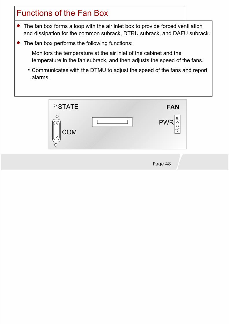
Functions of the Fan BoxThe fan box forms a loop with the air inlet box to provide forced ventilationand dissipation for the common subrack, DTRU subrack, and DAFU subrack.
The fan box performs the following functions:
Monitors the temperature at the air inlet of the cabinet and thetemperature in the fan subrack, and then adjusts the speed of the fans.
Communicates with the DTMU to adjust the speed of the fans and reportalarms.
FANSTATE
COMPWR
8/8/2019 37757175 2 HUAWEI BTS3012 Hardware Structure
http://slidepdf.com/reader/full/37757175-2-huawei-bts3012-hardware-structure 49/68
Page 49
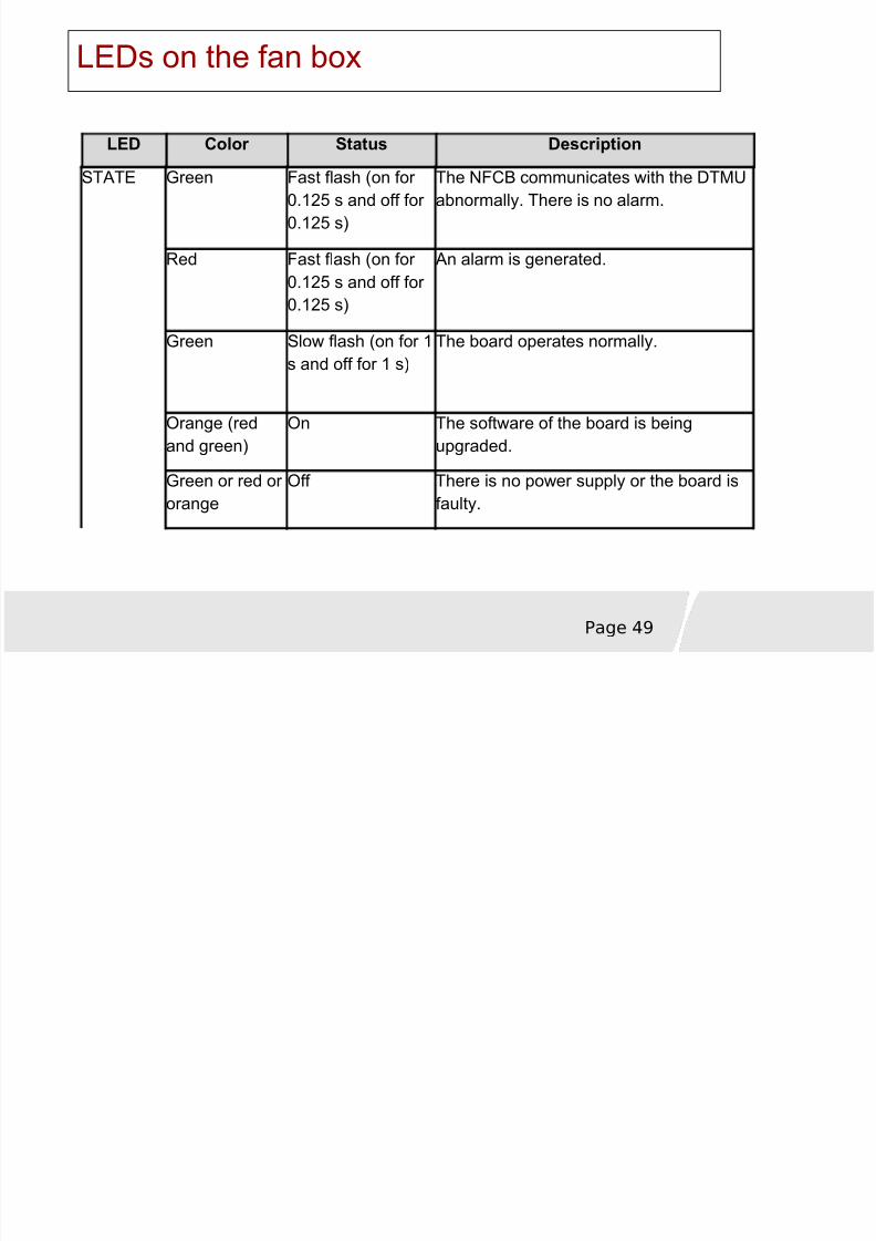
LEDs on the fan box
LED Color Status Description
STATE Green Fast flash (on for 0.125 s and off for 0.125 s)
The NFCB communicates with the DTMUabnormally. There is no alarm.
Red Fast flash (on for 0.125 s and off for 0.125 s)
An alarm is generated.
Green Slow flash (on for 1s and off for 1 s)
The board operates normally.
Orange (redand green)
On The software of the board is beingupgraded.
Green or red or orange
Off There is no power supply or the board isfaulty.
8/8/2019 37757175 2 HUAWEI BTS3012 Hardware Structure
http://slidepdf.com/reader/full/37757175-2-huawei-bts3012-hardware-structure 50/68
Page 50
Chapter 1 OverviewChapter 1 Overview
Chapter 2 System ComponentsChapter 2 System Components
Chapter 3 Signal ProcessingChap ter 3 Signal Processing
Chapter 4 Typical configurationChapter 4 Typical configuration
8/8/2019 37757175 2 HUAWEI BTS3012 Hardware Structure
http://slidepdf.com/reader/full/37757175-2-huawei-bts3012-hardware-structure 51/68
Page 51
Signal Flow of the BTS3012 Ⅱ
The BTS3012 signal flow is associated with the traffic andⅡ
signaling of the BTS.
The BTS3012 signal flow consists of:Ⅱ
DL traffic signal flow
UL traffic signal flow
Signaling processing signal flow
Signal flow for cabinet groups
Ⅱ
8/8/2019 37757175 2 HUAWEI BTS3012 Hardware Structure
http://slidepdf.com/reader/full/37757175-2-huawei-bts3012-hardware-structure 52/68
Page 52
DL Traffic Signal Flow of the BTS3012 Ⅱ
DL T ffi Sig l Fl
8/8/2019 37757175 2 HUAWEI BTS3012 Hardware Structure
http://slidepdf.com/reader/full/37757175-2-huawei-bts3012-hardware-structure 53/68
Page 53
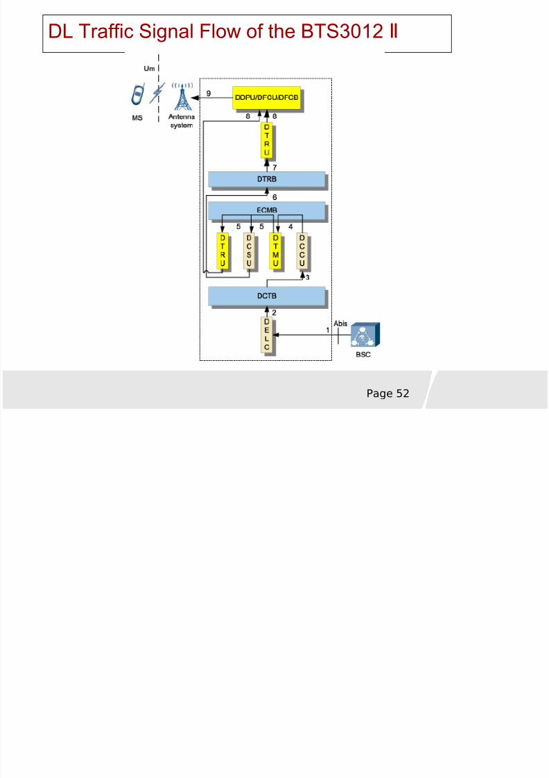
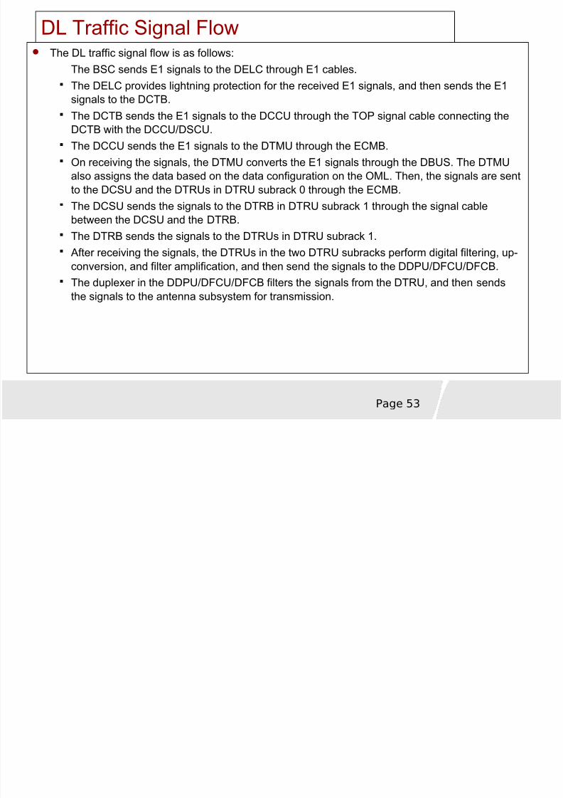
DL Traffic Signal FlowThe DL traffic signal flow is as follows:
The BSC sends E1 signals to the DELC through E1 cables.The DELC provides lightning protection for the received E1 signals, and then sends the E1
signals to the DCTB.The DCTB sends the E1 signals to the DCCU through the TOP signal cable connecting theDCTB with the DCCU/DSCU.The DCCU sends the E1 signals to the DTMU through the ECMB.On receiving the signals, the DTMU converts the E1 signals through the DBUS. The DTMUalso assigns the data based on the data configuration on the OML. Then, the signals are sentto the DCSU and the DTRUs in DTRU subrack 0 through the ECMB.
The DCSU sends the signals to the DTRB in DTRU subrack 1 through the signal cablebetween the DCSU and the DTRB.The DTRB sends the signals to the DTRUs in DTRU subrack 1.After receiving the signals, the DTRUs in the two DTRU subracks perform digital filtering, up-conversion, and filter amplification, and then send the signals to the DDPU/DFCU/DFCB.The duplexer in the DDPU/DFCU/DFCB filters the signals from the DTRU, and then sends
the signals to the antenna subsystem for transmission.
8/8/2019 37757175 2 HUAWEI BTS3012 Hardware Structure
http://slidepdf.com/reader/full/37757175-2-huawei-bts3012-hardware-structure 54/68
Page 54
UL Traffic Signal Flow of the BTS3012 Ⅱ
UL Traffic Signal Flow
8/8/2019 37757175 2 HUAWEI BTS3012 Hardware Structure
http://slidepdf.com/reader/full/37757175-2-huawei-bts3012-hardware-structure 55/68
Page 55
UL Traffic Signal Flow
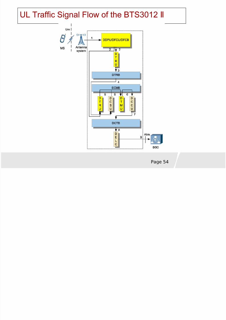
The UL traffic signal flow is as follows:
The antenna receives the signals from the MS. After being amplified by theTMA, the signals are transmitted to the DDPU/DFCU/DFCB through thefeeder. The TMA is optional. It is used to compensate the feeder loss andenhance receive sensitivity of the DDPU/DFCU/DFCB antenna port.
The DDPU/DFCU/DFCB receives the UL signals and transmits the signals
to the DTRUs in the two DTRU subracks after they are filtered by theduplexer and amplified by the lower noise amplifier (LNA).
The DTRU in DTRU subrack 1 receives the signals from theDDPU/DFCU/DFCB and transmits the signals to the DTRB after amplification and down-conversion.
The DTRB sends the signals to the DCSU.
UL Traffic Signal Flow
8/8/2019 37757175 2 HUAWEI BTS3012 Hardware Structure
http://slidepdf.com/reader/full/37757175-2-huawei-bts3012-hardware-structure 56/68
Page 56
UL Traffic Signal Flow
The DCSU sends the signals to the DTMU through the ECMB. In addition, theDTRU in DTRU subrack 0 receives the signals from the DDPU/DFCU/DFCB,and transmits the signals to the DTMU through the ECMB after amplification anddown conversion.
The DTMU backs up the E1 signals and converts the E1 signals through theDBUS. The DTMU then sends the converted signals to the DCCU through theECMB.
The DCCU sends the signals to the DCTB through the TOP signal cableconnecting the DCTB with the DCCU/DSCU.
The DCTB sends the signals to the DELC.
The DELC provides lightning protection for the signals. Then, it sends the
signals to the BSC through the E1 cables.
8/8/2019 37757175 2 HUAWEI BTS3012 Hardware Structure
http://slidepdf.com/reader/full/37757175-2-huawei-bts3012-hardware-structure 57/68
8/8/2019 37757175 2 HUAWEI BTS3012 Hardware Structure
http://slidepdf.com/reader/full/37757175-2-huawei-bts3012-hardware-structure 58/68
Page 58
Signaling processing flow
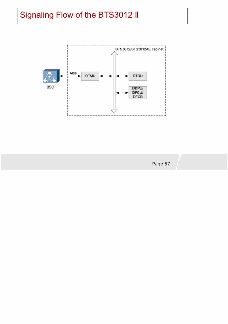
The signaling processing flow is as follows:
The BSC sends the signaling data to the DTMU of the BTS.
After processing the signaling, the DTMU sends the signaling to theDTRU and DDPU (DFCU or DFCB).
The DTRU and DDPU (DFCU or DFCB) report their board status tothe DTMU.
The DTMU obtains the status of the BTS3012 by collecting andanalyzing the states of all the boards. Then, it transmits theinformation to the BSC through the Abis interface.
8/8/2019 37757175 2 HUAWEI BTS3012 Hardware Structure
http://slidepdf.com/reader/full/37757175-2-huawei-bts3012-hardware-structure 59/68
Page 59
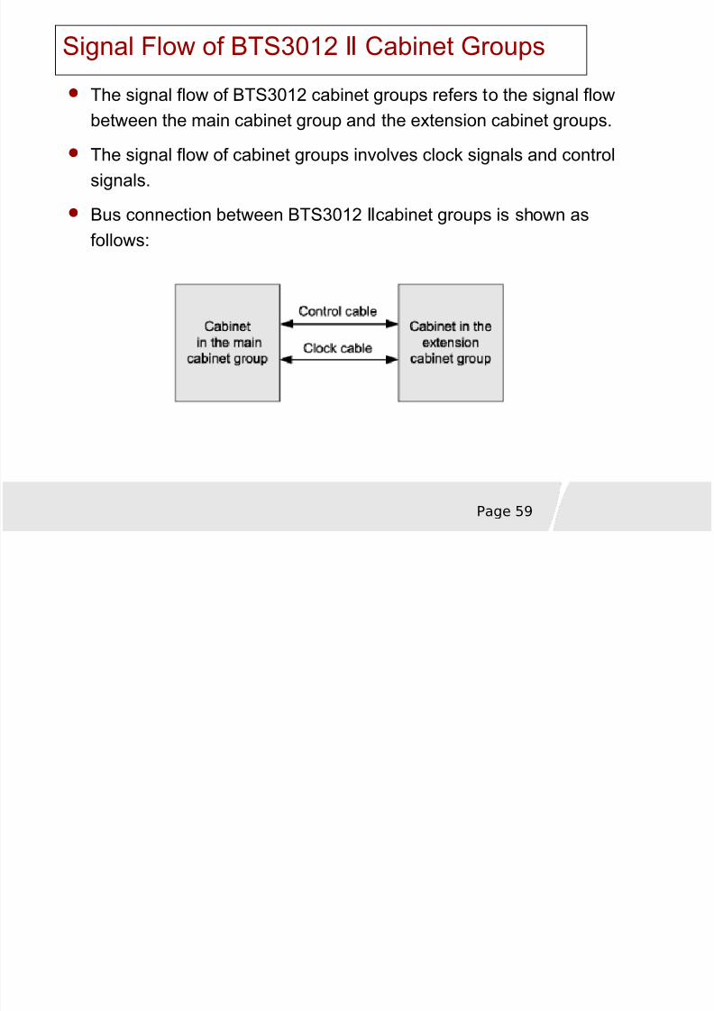
Signal Flow of BTS3012 Cabinet GroupsⅡ
The signal flow of BTS3012 cabinet groups refers to the signal flowbetween the main cabinet group and the extension cabinet groups.
The signal flow of cabinet groups involves clock signals and controlsignals.
Bus connection between BTS3012 cabinet groups is shown asⅡ
follows:
8/8/2019 37757175 2 HUAWEI BTS3012 Hardware Structure
http://slidepdf.com/reader/full/37757175-2-huawei-bts3012-hardware-structure 60/68
Page 60
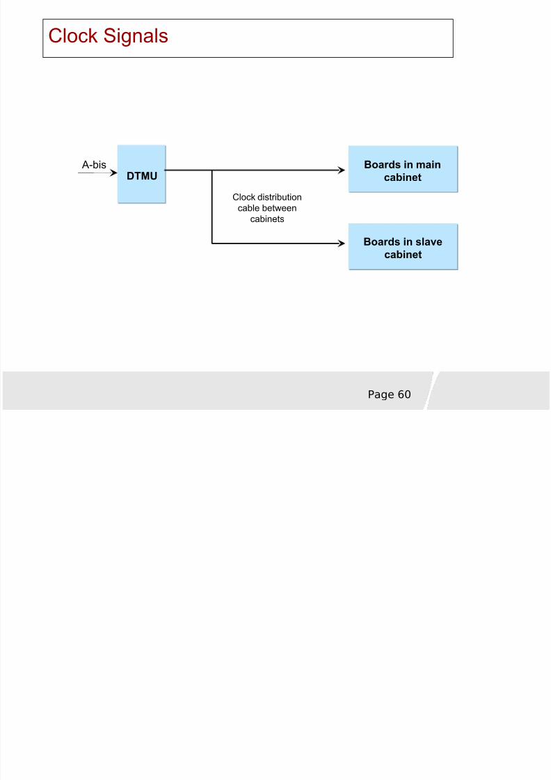
Clock Signals
DTMUBoards in main
cabinet
Boards in slavecabinet
A-bis
Clock distributioncable betweencabinets
8/8/2019 37757175 2 HUAWEI BTS3012 Hardware Structure
http://slidepdf.com/reader/full/37757175-2-huawei-bts3012-hardware-structure 61/68
Page 61
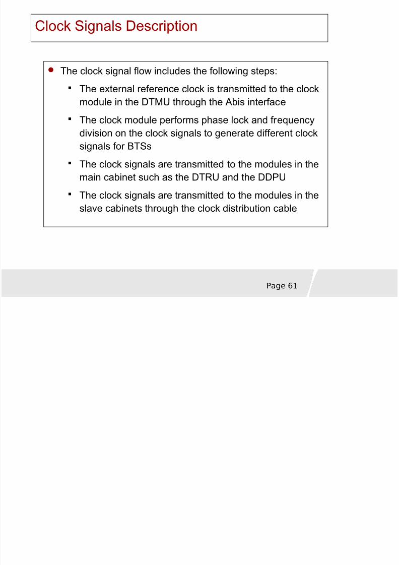
Clock Signals Description
The clock signal flow includes the following steps:The external reference clock is transmitted to the clockmodule in the DTMU through the Abis interface
The clock module performs phase lock and frequencydivision on the clock signals to generate different clock
signals for BTSs
The clock signals are transmitted to the modules in themain cabinet such as the DTRU and the DDPU
The clock signals are transmitted to the modules in theslave cabinets through the clock distribution cable
8/8/2019 37757175 2 HUAWEI BTS3012 Hardware Structure
http://slidepdf.com/reader/full/37757175-2-huawei-bts3012-hardware-structure 62/68
Page 62
Chapter 1 OverviewChapter 1 Overview
Chapter 2 System ComponentsChapter 2 System Components
Chapter 3 Signal ProcessingChapter 3 Signal Processing
Chapter 4 Typical configurationChap ter 4 Typical configuration
8/8/2019 37757175 2 HUAWEI BTS3012 Hardware Structure
http://slidepdf.com/reader/full/37757175-2-huawei-bts3012-hardware-structure 63/68
Page 63
Configuration Principles for the BTS3012 Ⅱ
Configure the BTS3012 according to the following principles:Use a minimum number of antennas.
Use a minimum number of cabinets.
Configure all the TRXs that belong to one synchronized cell in onecabinet group.
Adhere to the following principles when configuring the BTS3012 cabinets:
If less than 18 TRXs are required in the synchronized cells of a site, useone cabinet to configure the site.
If more than 18 TRXs are required in the synchronized cells of a site, usecabinet groups to configure the site.
8/8/2019 37757175 2 HUAWEI BTS3012 Hardware Structure
http://slidepdf.com/reader/full/37757175-2-huawei-bts3012-hardware-structure 64/68
Page 64
Configuration Features for the BTS3012 Ⅱ
The BTS3012 has the following features in terms of configuration:Supports omnidirectional cell coverage and directional cell coverage
Supports the grouping of three cabinets
The RF TX mode supports wideband combining, PBT, transmit diversity,and non-combining. The DTRU connected to the DFCU does not supportthe wideband combining mechanism.
The RF RX mode supports the receive diversity, independent receive,and four-way receive diversity.
Typical Configuration of One BTS3012 Cabinet S2/2/2Ⅱ
8/8/2019 37757175 2 HUAWEI BTS3012 Hardware Structure
http://slidepdf.com/reader/full/37757175-2-huawei-bts3012-hardware-structure 65/68
Page 65
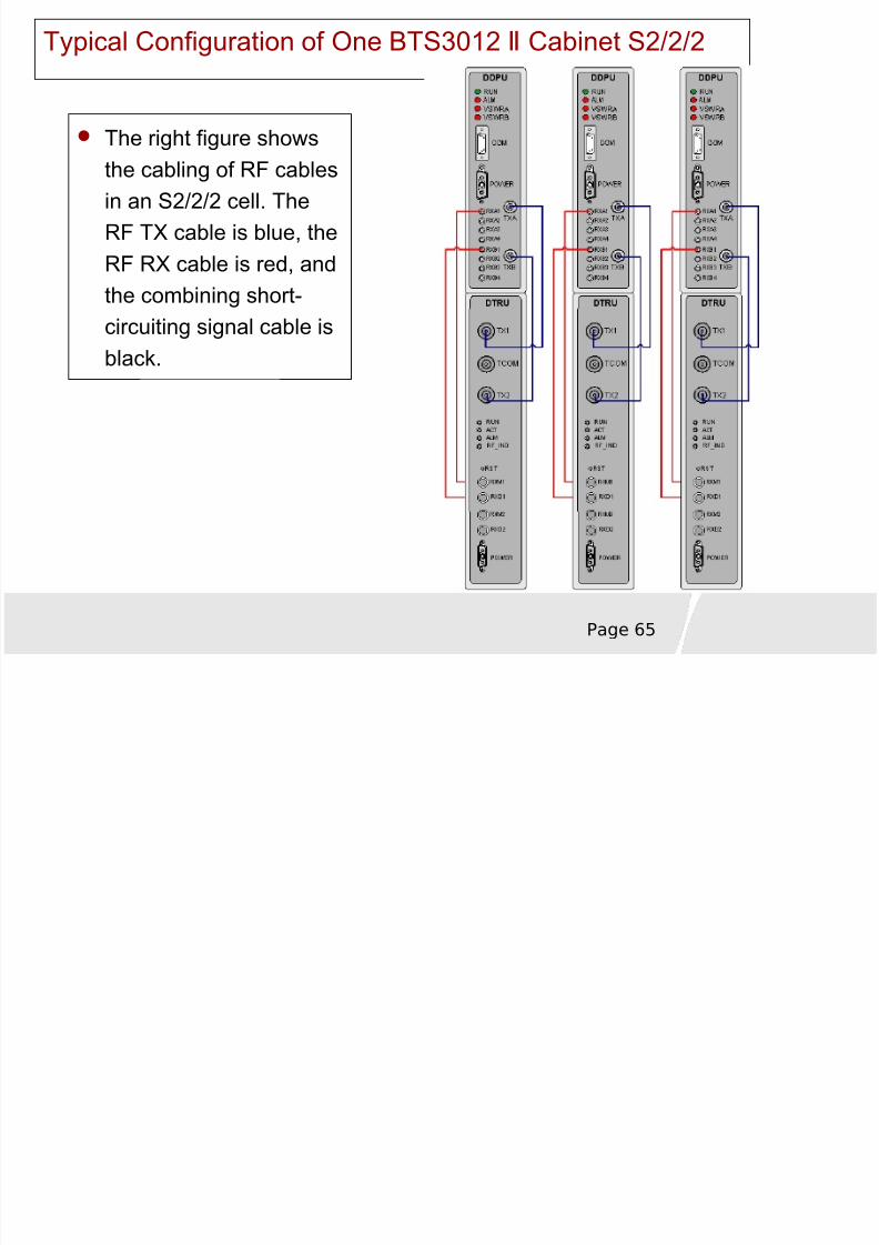
Typical Configuration of One BTS3012 Cabinet S2/2/2Ⅱ
The right figure shows
the cabling of RF cablesin an S2/2/2 cell. TheRF TX cable is blue, theRF RX cable is red, andthe combining short-circuiting signal cable isblack.
Typical Configuration of One BTS3012 CabinetⅡ
8/8/2019 37757175 2 HUAWEI BTS3012 Hardware Structure
http://slidepdf.com/reader/full/37757175-2-huawei-bts3012-hardware-structure 66/68
Page 66
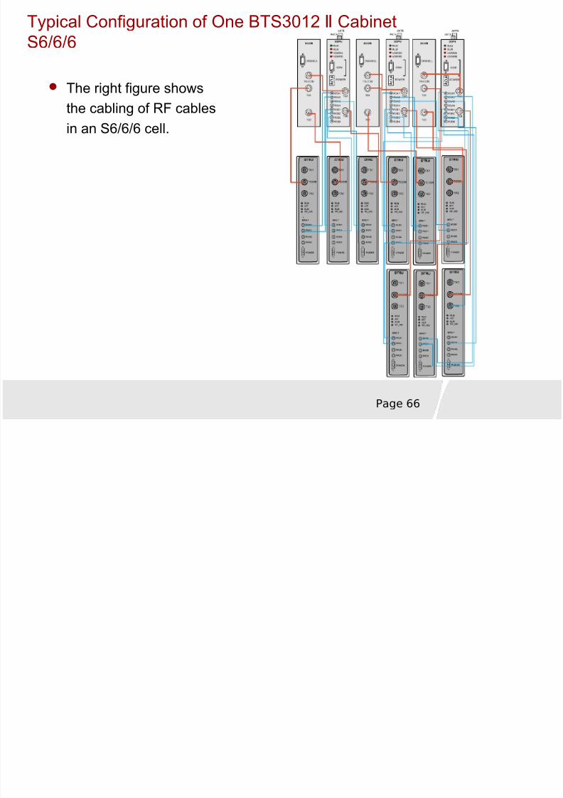
The right figure shows
the cabling of RF cablesin an S6/6/6 cell.
S6/6/6
8/8/2019 37757175 2 HUAWEI BTS3012 Hardware Structure
http://slidepdf.com/reader/full/37757175-2-huawei-bts3012-hardware-structure 67/68
Page 67
Functions and features of BTS3012
BTS3012 hardware structureSystem Signal Flow
Typical configuration
SummarySummary

8/8/2019 37757175 2 HUAWEI BTS3012 Hardware Structure
http://slidepdf.com/reader/full/37757175-2-huawei-bts3012-hardware-structure 68/68
www.huawei.com
Thank You